

Page 1
Operation/Reference Guide
Modero® 1200V
G4 Touch Panels
NXD-1200V and NXT-1200V
12” Modero Video Touch Panels
Touch Panels
Last Revised: 10/1/2008
Page 2

AMX Limited Warranty and Disclaimer
AMX warrants its products to be free of defects in material and workmanship under normal use for three (3) years from
the date of purchase from AMX, with the following exceptions:
• Electroluminescent and LCD Control Panels are warranted for three (3) years, except for the display and touch
overlay components that are warranted for a period of one (1) year.
• Disk drive mechanisms, pan/tilt heads, power supplies, and MX Series products are warranted for a period of one
(1) year.
• AMX Lighting products are guaranteed to switch on and off any load that is properly connected to our lighting
products, as long as the AMX Lighting products are under warranty. AMX does guarantee the control of dimmable
loads that are properly connected to our lighting products. The dimming performance or quality cannot be
guaranteed due to the random combinations of dimmers, lamps and ballasts or transformers.
• Unless otherwise specified, OEM and custom products are warranted for a period of one (1) year.
• AMX Software is warranted for a period of ninety (90) days.
• Batteries and incandescent lamps are not covered under the warranty.
This warranty extends only to products purchased directly from AMX or an Authorized AMX Dealer.
All products returned to AMX require a Return Material Authorization (RMA) number. The RMA number is obtained
from the AMX RMA Department. The RMA number must be clearly marked on the outside of each box. The RMA is
valid for a 30-day period. After the 30-day period the RMA will be cancelled. Any shipments received not consistent
with the RMA, or after the RMA is cancelled, will be refused. AMX is not responsible for products returned without a
valid RMA number.
AMX is not liable for any damages caused by its products or for the failure of its products to perform. This includes any
lost profits, lost savings, incidental damages, or consequential damages. AMX is not liable for any claim made by a
third party or by an AMX Dealer for a third party.
This limitation of liability applies whether damages are sought, or a claim is made, under this warranty or as a tort claim
(including negligence and strict product liability), a contract claim, or any other claim. This limitation of liability cannot
be waived or amended by any person. This limitation of liability will be effective even if AMX or an authorized
representative of AMX has been advised of the possibility of any such damages. This limitation of liability, however, will
not apply to claims for personal injury.
Some states do not allow a limitation of how long an implied warranty last. Some states do not allow the limitation or
exclusion of incidental or consequential damages for consumer products. In such states, the limitation or exclusion of
the Limited Warranty may not apply. This Limited Warranty gives the owner specific legal rights. The owner may also
have other rights that vary from state to state. The owner is advised to consult applicable state laws for full
determination of rights.
EXCEPT AS EXPRESSLY SET FORTH IN THIS WARRANTY, AMX MAKES NO OTHER WARRANTIES,
EXPRESSED OR IMPLIED, INCLUDING ANY IMPLIED WARRANTIES OF MERCHANTABILITY OR FITNESS FOR
A PARTICULAR PURPOSE. AMX EXPRESSLY DISCLAIMS ALL WARRANTIES NOT STATED IN THIS LIMITED
WARRANTY. ANY IMPLIED WARRANTIES THAT MAY BE IMPOSED BY LAW ARE LIMITED TO THE TERMS OF
THIS LIMITED WARRANTY.
Page 3
FCC Information
This device complies with Part 15 of the FCC Rules. Operation is subject to the following two conditions: (1) this device
may not cause harmful interference, and (2) this device must accept any interference received; including interference
that may cause undesired operation.
Federal Communications Commission (FCC)
Statement
This equipment has been tested and found to comply with the limits for a Class B digital device, pursuant to Part 15 of
the FCC rules. These limits are designed to provide reasonable protection against harmful interference in a residential
installation. This equipment generates, uses and can radiate radio frequency energy, and, if not installed and used in
accordance with the instructions, may cause harmful interference to radio communications. However, there is no
guarantee that interference will not occur in a particular installation. If this equipment does cause harmful
interference to radio or television reception, which can be determined by turning the equipment off and on, the user is
encouraged to try to correct the interference by one or more of the following measures:
• Reorient or relocate the receiving antenna.
• Increase the separation between the equipment and receiver.
• Connect the equipment into an outlet on a circuit different from that to which the receiver is connected.
• Consult the dealer or an experienced radio/TV technician for help.
FCC RF Radiation Exposure Statement
This transmitter must not be co-located or operating in conjunction with any other antenna or transmitter. This
equipment complies with FCC RF radiation exposure limits set forth for an uncontrolled environment. This equipment
should be installed an operated with a minimum distance of 20 centimeters between the radiator and your body.
Page 4

Page 5

Table of Contents
Table of Contents
Introduction ........................................................................................................1
Modero Video Touch Panels (1200V-Series) ............................................................. 1
Product Specifications (NXD-1200V and NXT-1200V) .............................................. 2
1200V-Series Modero Connectors ............................................................................ 5
Cleaning the Touch Overlay ............................................................................................ 5
Connecting and Using Input Devices ........................................................................ 6
Touch Panel Accessories ..................................................................................... 7
NXA-AVB/ETHERNET Breakout Box (FG2254-10) .................................................... 7
Product Specifications .................................................................................................... 7
Installing the NXA-AVB/ETHERNET ................................................................................ 8
Wiring the NXA-AVB/ETHERNET connectors and cables ................................................ 9
Wiring the NXA-AVB/ETHERNET for Unbalanced Audio............................................... 10
Wiring the NXA-AVB/ETHERNET for Balanced Audio................................................... 10
Modero Table Top Cable (CA2250-50) ................................................................... 11
Product Specifications .................................................................................................. 11
Wiring information for the Modero Table Top cable..................................................... 12
Installing CAT5 Suppression Ferrites............................................................................. 14
NXA-CFTP Compact Flash (FG2116-2x) .................................................................. 15
NXA-PCI80211G Wireless Card (FG2255-04).......................................................... 16
Product Specifications ............................................................................................... 16
Installation and Upgrade of the Internal NXT Components.................................... 18
Step 1: Remove the existing NXT Outer Housing......................................................... 18
Step 2: Install the 802.11g mini-PCI Wireless Card ....................................................... 19
Step 3: Install the Compact Flash Memory Card upgrade............................................. 21
Step 4: Close and Resecure the NXT Panel Enclosure................................................... 22
Installation and Upgrade of the Internal NXD Components ................................... 22
Step 1: Remove the existing NXD Outer Housing ........................................................ 22
Step 2: Install the new 802.11g mini-PCI Wireless card (NXD)...................................... 23
Step 3: Install the new Compact Flash Memory card (NXD).......................................... 23
Step 4: Close and Resecure the NXD Panel Enclosure .................................................. 24
NXT-BP Power Pack (FG2255-10) ........................................................................... 25
Product Specifications................................................................................................... 25
NXA-BASE/B Battery Base Kit (FG2255K) .............................................................. 25
Product Specifications .................................................................................................. 26
Checking the NXT-BP battery charge............................................................................ 26
Installing the NXA-BASE/B to an NXT Modero Panel.................................................... 27
Installing an NXT-BP into the NXA-BASE/B................................................................... 28
1200V Modero Video Touch Panels
i
Page 6

Table of Contents
Charging the NXT-BP batteries with the NXA-BASE/B ................................................. 29
NXT-CHG Battery Charger Kit (FG2255-50K) ......................................................... 29
Product Specifications .................................................................................................. 30
Powering the NXT-CHG ................................................................................................ 30
Reading NXT-CHG LED Indicator .................................................................................. 30
Charging the NXT-BP batteries using the NXT-CHG..................................................... 31
Recalibrating the batteries............................................................................................ 31
Installation Procedures: NXD-1200V Panels .....................................................33
Unpacking the Panel ............................................................................................... 33
Installing the Internal Components ......................................................................... 33
Upgrading to the MB-TP12 VESA Mounting Kit ..................................................... 33
Removing the Original Modero Back Box ..................................................................... 34
Installing the MP-TP12 Back Box................................................................................... 34
Cable Installation for the MP-TP12 Back Box ................................................................ 35
Finalizing the installation............................................................................................... 35
Pre-wall Installation of the Conduit Box.................................................................. 37
Installation of the NXD Touch Panel ....................................................................... 38
Installing the NXD panel within a Conduit Box ............................................................. 38
Installing the NXD into drywall using Expansion Clips .................................................. 40
Installing the NXD into a Flat Surface using #4 screws ................................................. 42
Installing an NXD into an (optional) Rack Mount Kit (NXA-RK12) ................................. 44
Wiring Guidelines for the 1200V Panels ................................................................. 45
Preparing captive wires................................................................................................. 45
Wiring a power connection ........................................................................................... 46
Audio/Video Port: Connections and Wiring ............................................................ 46
Ethernet/RJ-45 Port: Connections and Wiring ........................................................ 47
Panel Calibration ..............................................................................................49
Calibrating the Modero Panel................................................................................. 49
Testing your Calibration................................................................................................ 50
Configuring Communication .............................................................................51
Modero Setup and System Connection .................................................................. 51
Configuring and Using USB with a Virtual Master .................................................. 53
Step 1: Setting up the Panel and PC for USB Communication ...................................... 53
Step 2: Confirming the Installation of the USB Driver on the PC .................................. 54
Step 3: Confirm and View the current AMX USB device connections ........................... 56
Step 4: Using a USB to Configure a Virtual Master (using NetLinx Studio) ................... 56
Step 5: Confirm and View the current AMX USB device connections ........................... 58
Wireless Settings Page - Wireless Access Overview ............................................... 59
IP Routing...................................................................................................................... 59
ii
1200V Modero Video Touch Panels
Page 7

Table of Contents
Hot Swapping ............................................................................................................... 59
Configuring a Wireless Connection......................................................................... 60
Step 1: Configuring the Panel’s Wireless IP Settings .............................................. 60
Wireless communication using a DHCP Address ........................................................... 60
Wireless communication using a Static IP Address........................................................ 61
Step 2: Configuring the Card’s Wireless Security Settings ..................................... 62
Configuring the Modero’s wireless card for unsecured access to a WAP200G............. 62
Configuring the Modero’s wireless card for secured access to a WAP200G................. 63
Configuring multiple wireless Moderos to communicate to a target WAP200G........... 66
Configuring a Wired Ethernet Connection.............................................................. 67
Step 1: Configuring the Panel’s Wired IP Settings.................................................. 67
IP Settings section - Configuring a DHCP Address over Ethernet................................. 67
IP Settings section - Configuring a Static IP Address over Ethernet ............................. 68
Step 2: Choosing a Master Connection Mode Setting............................................ 68
Step 3: Configuring the Ethernet Connection Type................................................ 69
Master Connection - Virtual Master communication over Ethernet............................... 70
Master Connection section - NetLinx Master Ethernet IP Address - URL Mode............ 72
Master Connection section - NetLinx Master Ethernet IP Address - Listen Mode......... 72
Master Connection section - NetLinx Master Ethernet IP Address - Auto Mode .......... 73
Using G4 Web Control to Interact with a G4 Panel ................................................ 74
Using your NetLinx Master to control the G4 panel ............................................... 76
Upgrading Modero Firmware ...........................................................................79
Upgrading the Modero Firmware via the USB port ................................................ 79
Step 1: Configure the panel for a USB Connection Type .............................................. 79
Step 2: Prepare NetLinx Studio for communication via the USB port ........................... 80
Step 3: Confirm and Upgrade the firmware via the USB port....................................... 81
Upgrading the Modero Firmware via an IP Address ............................................... 83
Step 1: Prepare the Master for communication via an IP .............................................. 83
Step 2: Prepare the panel for communication via an IP ................................................ 84
Step 3: Verify and Upgrade the panel firmware via an IP ............................................. 85
Upgrading Accessory Devices via the USB ............................................................. 86
Step 1: Prepare the NXA-BASE/B for firmware transfer via USB .................................. 87
Step 2: Upgrade the NXA-BASE/B firmware via USB.................................................... 88
Upgrading Accessory Devices via an IP Address .................................................... 89
Step 1: Prepare the NXA-BASE/B for firmware transfer via an IP ................................. 89
Step 2: Upgrade the NXA-BASE/B firmware via an IP................................................... 90
Firmware Pages and Descriptions ....................................................................93
Setup Navigation Buttons....................................................................................... 93
Setup Page ............................................................................................................. 94
1200V Modero Video Touch Panels
iii
Page 8

Table of Contents
Project Information Page............................................................................................... 96
Panel Information Page................................................................................................. 97
Time & Date Setup Page ............................................................................................... 98
Volume Page ................................................................................................................. 99
Supported sampling rates for WAV............................................................................. 100
Protected Setup Page ................................................................................................. 100
Video Adjustment Slide-Out Option Bar ..................................................................... 101
Video Adjustment - Video Adjustment Page............................................................... 101
Battery Base Page ....................................................................................................... 102
Protected Setup Navigation Buttons .................................................................... 104
Protected Setup Page........................................................................................... 105
G4 Web Control Page ................................................................................................. 108
Sensor Setup Page ...................................................................................................... 110
Using the Automated Brightness Control feature (DIM Mode) ................................... 111
Password Setup Page.................................................................................................. 112
Calibration Page.......................................................................................................... 113
Wireless Settings Page................................................................................................ 114
System Settings Page.................................................................................................. 118
Programming ..................................................................................................121
Button Assignments ............................................................................................. 121
Page Commands ................................................................................................... 121
Programming Numbers......................................................................................... 127
RGB triplets and names for basic 88 colors ................................................................ 127
Font styles and ID numbers......................................................................................... 129
Border styles ............................................................................................................... 130
"^" Button Commands ......................................................................................... 132
Text Effect Names ................................................................................................ 152
Button Query Commands ..................................................................................... 153
Panel Runtime Operations .................................................................................... 162
Input Commands................................................................................................... 166
Embedded Codes ................................................................................................. 168
Panel Setup Commands ........................................................................................ 169
Dynamic Image Commands................................................................................... 170
Troubleshooting .............................................................................................173
Appendix A ....................................................................................................177
Text Formatting Codes for Bargraphs/Joysticks ................................................... 177
Text Area Input Masking....................................................................................... 178
Input mask character types ......................................................................................... 178
Input mask ranges....................................................................................................... 179
iv
1200V Modero Video Touch Panels
Page 9

Table of Contents
Input mask next field characters ................................................................................. 179
Input mask operations................................................................................................. 179
Input mask literals ....................................................................................................... 179
Input mask output examples....................................................................................... 180
URL Resources ...................................................................................................... 181
Special escape sequences ........................................................................................... 181
1200V Modero Video Touch Panels
v
Page 10

Table of Contents
vi
1200V Modero Video Touch Panels
Page 11
Introduction
AMX has taken a great leap forward with the release of their new 1200V-Series of Modero touch panels.
These panels offer the ability to display Composite video, 802.11g communication, and USB support for
extended input devices, and panel programming via a mini-USB port. The new G4 graphics and Video
technology is supported by the release of the latest TPDesign4 Touch Panel Design Program. These
video-capable panels support several video formats: NTSC, SECAM, and PAL (Color Active (CA)
panels don’t support video).
Each 1200V-Series panels have been pre-installed with 2 antennas which can be later used to
configure each panel type for wireless communication (via an optional NXA-80211G wireless
mini-PCI card).
Modero Video Touch Panels (1200V-Series)
The new and enhanced line of 12" Modero Touch Panel (NXT/NXD-1200V) represent the next step in
video-capable panels and departs from the previously popular CA version. In addition to
Composite/S-Video support (does not support Component RGB signals), the new 1200V panels feature
dual USB connectivity for mouse and keyboard, and antennas, the use of a mini-USB port for panel
programming and a complete departure from the use of an ICSNet connector for communication. These
panels include a built-in microphone, left/right speakers, audio/headphone connector, and an included
audio/video breakout box.
Table Top models use AMX’s exclusive SmoothTilt
viewing angle.
Each panel is sold only as part of a 1200V Kit which includes both a panel and an
NXA-AVB/ETHERNET Audio/Video Breakout Box (FG2254-10). This box facilitates the installation
and distribution of video, data, and audio to Modero touch panels located up to 200 feet (60.96 m) from
the breakout box. These panels are ideally suited for displaying full motion video and audio with overlay
graphics for applications with demanding visual requirements. The following is a listing of the currently
available 1200V panels:
Introduction
®
technology for effortless adjustment of the
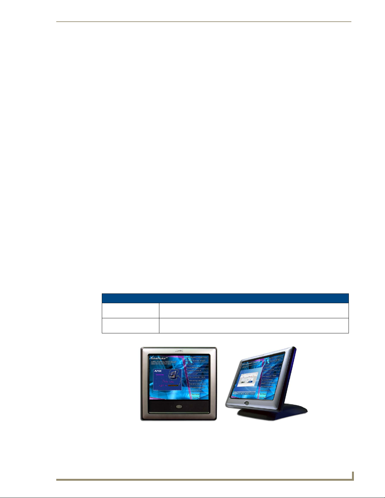
1200-V Modero Video Touch Panels
NXD-1200V
(FG2251-60K)
NXT-1200V
(FG2250-60K)
Sample
NXD-1200V
(front view)
Sample 1200V Video Touch Panels (front views)
FIG. 1
1200V Modero Video Touch Panels
12" Modero Video WallMount Touch Panel Kit
(includes both an NXD panel and an NXA-AVB/ETHERNET A/V Breakout Box).
12" Modero Video Table Top Touch Panel Kit
(includes both an NXD panel and an NXA-AVB/ETHERNET A/V Breakout Box).
Sample
NXT-1200V
(front view)
1
Page 12
Introduction
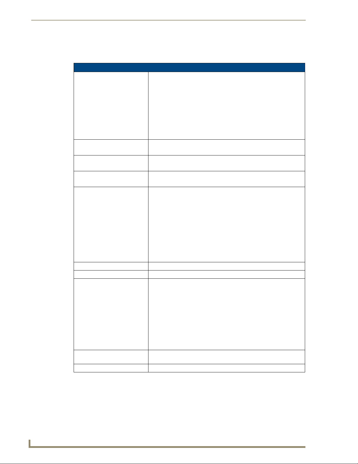
Product Specifications (NXD-1200V and NXT-1200V)
The following table outlines the specifications for 1200V-Series of 12" Modero panels.
1200V Panel Specifications
Dimensions (HWD): • NXD-1200V (with faceplate): 12.38" x 12.59" x 3.25"
(31.43 cm x 31.97 cm x 8.25 cm)
• NXT-1200V (Fully raised): 10.91" x 12.34" x 12.50"
(27.70 cm x 31.33 cm x 31.75 cm)
• NXT-1200V (Fully lowered): 6.77" x 12.34" x 12.50"
(17.20 cm x 31.33 cm x 31.75 cm)
• CB-TP12 (conduit/wallbox): 11.52" x 11.60" x 3.50"
(29.27 cm x 29.47 cm x 8.89 cm)
• MB-TP12 (VESA mounting box): 12.37" x 12.58" x 3.52"
(31.42 cm x 31.95 cm x 8.94 cm)
Power Requirements: • Constant current draw: 2.1 A @ 12 VDC (stand-alone)
• Startup current draw: 3.2 A @ 12 VDC (stand-alone)
Memory (factory default): • 256 MB on-board memory
• 128 MB Compact Flash (upgradeable to 1 GB factory programmed)
Weight: • NXD-1200V: 10.80 lbs (4.90 kg)
• NXT-1200V: 10.80 lbs (4.90 kg)
Panel LCD Parameters: • Aspect Ratio: 4 x 3
• Brightness (luminance): 250 cd/m
• Channel transparency: 8-bit Alpha channel transparency
• Contrast ratio: 300:1
• Display area (HW): 183.10 mm x 247.40 mm
• Display colors: 256K (18-bit color depth)
• Dot/Pixel pitch: 0.297 mm
• Screen resolution (HV): 800 x 600 pixels
• Video formats: NTSC, PAL, and SECAM (shown within variable-size
video windows)
Active Screen Area: • 9.68” x 7.26” (24.60cm x 18.45cm)
Viewing Angles: • Vertical: + 80° (up from center) and - 80° (down from center)
Features: • Enhanced hardware security (via an externally mounted Kensington
Supported Audio Sample Rates: • 48000Hz, 44100Hz, 32000Hz, 24000Hz, 22050Hz, 16000Hz, 12000Hz,
Certifications: • FCC Part 15 Class B, CE, and EN 60950
Lock system)
• Ethernet connectivity (replaced ICSNet as a method of communication)
• New and improved connector compartment
• Pre-installed 802.11g wireless card and integrated antennas (NXT
models only)
• Wired Ethernet @10/100 and Wireless Ethernet 802.11g
• USB mouse/keyboard/programming ports
• Support of the latest G4 applications: G4 Computer Control, G4Web
®
Control
11025Hz, and 8000Hz.
, Dynamo, TakeNote™, and PictureFrame™.
2
2
1200V Modero Video Touch Panels
Page 13
Introduction
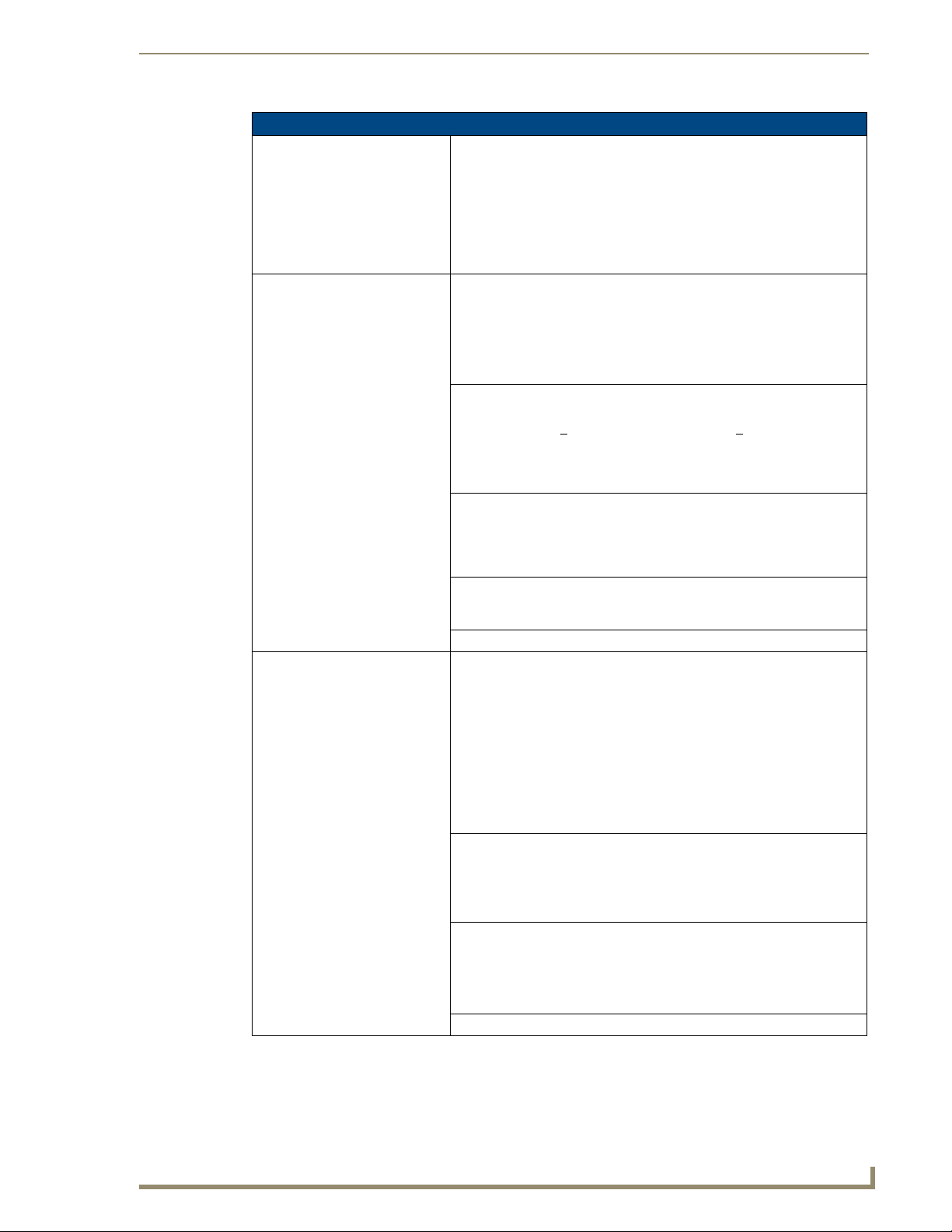
1200V Panel Specifications (Cont.)
Button Assignments: Button assignments can only be adjusted in TPD4 and not on the panels.
• Button channel range: 1 - 4000 button push and Feedback (per address
port)
• Button variable text range: 1 - 4000 (per address port)
• Button states range: 1 - 256 (General Button; 1 = Off State, 2 = On State)
• Level range: 1 - 600 (default level value 0-255, can be set up to 1-65535)
• Address port range: 1 - 100
Front Panel Components:
Light sensor: • Photosensitive light detector for automatic adjustment of the panel
Motion sensor (PIR): • Proximity Infrared Detector to wake the panel when the panel is
Front setup access button: • Provides both access to the Setup and Calibration pages and toggles the
Microphone: • Used for intercom applications
Speakers: • Stereo output with a frequency response of 450 Hz - 7 KHz
Rear Panel Components: (Side panel location on NXD-Wall Mount panels)
Audio/Video connector: • RJ-45 connector for communication of differential audio/video signals
Ethernet 10/100 port: • RJ-45 port for 10/100 Mbps communication. The Ethernet port
Ethernet 10/100 LEDs: • LEDs show communication activity and connection information:
PWR connector: • 2-pin 3.5 mm mini-Phoenix connector.
brightness (a dim room results in a dimmer LCD display and a bright
room results in a brighter LCD display).
Note: The light sensor can be adjusted via the Sensor Setup Page section
on page 110.
approached.
• Activation range: +
20° vertically from center and + 45° horizontally
from center.
Note: The motion sensor can be adjusted via the Sensor Setup page
(Sensor Setup Page section on page 110).
panel between a "sleep" and "wake" state.
- When wired, "sleep" status means the backlight is Off.
- When battery operated, wireless "sleep" status means the touch panel
base is either Off or "suspended".
(requires an NXA-AVB/ETHERNET Breakout Box for analog
communication).
to/from the touch panel (panel type dependant). This connector receives
Composite video, Stereo (left/right) audio, and microphone audio.
• Video is received via the NXA-AVB/ETHERNET Breakout Box.
Configuring video windows for playback is done using TPDesign4.
• In-bound audio (from the breakout box) gets directed to the speakers.
• Out-bound audio is sent from the on-board microphone (on the
front-panel). Selecting audio files for playback is configured through
TPDesign4.
automatically negotiates the connection speed (10 Mbps or 100 Mbps),
and whether to use half duplex or full duplex mode.
®
• These panels communicate with the NetLinx
Master using the ICSP
protocol over Ethernet.
A-activity - Yellow LED lights when receiving or transmitting Ethernet
data packets.
L-link - Green LED lights when the Ethernet cables are connected and
terminated correctly.
1200V Modero Video Touch Panels
3
Page 14
Introduction
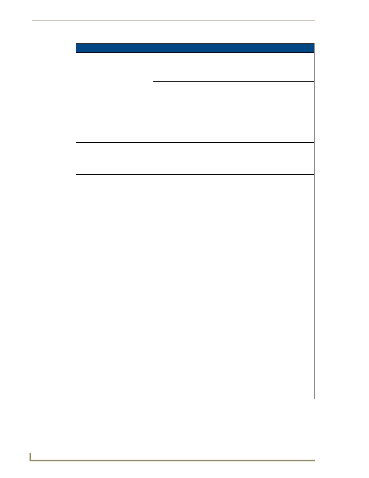
1200V Panel Specifications (Cont.)
Rear Panel Components
(Cont.):
Stereo Output connector: • Stereo output through a 3.5mm mini-jack (for use with external
USB connector (2): • The two Type-A USB ports can connect up to two external keyboard or
Mini-USB connector: • 5-pin Mini-USB connector used for programming, firmware update, and
Operating / Storage
Environment:
Included Accessories: • Installation Kit for 12" and 17" NXD panels (KA2251-01):
Other AMX Equipment: • CB-TP12 (FG031-10)
(Side panel location on NXD-Wall Mount panels)
speakers).
mouse devices for use with Virtual PC applications.
touch panel file transfer between the PC and the target panel.
Note: When connecting the panel to PC using a CC-USB (or compatible)
cable, be sure to power the panel On before attempting to connect the
USB cable from the PC to the mini-USB port on the panel.
Refer to Step 5: Confirm and View the current AMX USB device
connections section on page 58 for more information.
• Operating Temperature: 10° C (50° F) to 40° C (104° F)
• Operating Humidity: 20% to 85% RH
• Storage Temperature: -20° C (-4° F) to 60° C (140° F)
• Storage Humidity: 5% to 85% RH
- 2-pin mini-Phoenix connector (41-5025)
- Four Drywall clips (62-5924-05) and #6 - sheet metal screws
- One CAT5 Suppression Ferrites (04-0014)
- Three Phillips-head screws (#4-20 x 0.250 Black)
• Installation Kit for 12" NXT panels (KA2251-03):
- 2-pin mini-Phoenix connector (41-5025)
- Three Phillips-head screws (#4-20 x 0.250 Black)
- Two CAT5 Suppression Ferrites (04-0014)
• Modero Table Top Cable (CA2250-50)
- provided with all NXT Table Top panels.
• NXA-AVB/ETHERNET Breakout Box (FG2254-10): Provides video/audio
distribution to the A/V panel over CAT5 cable (up to 200’/60.96m) and
accepts either Composite or S-Video.
- Although the 1200V is only sold as part of a KIT configuration,
the breakout box can be purchased separately.
- 12" metallic conduit box for Wall Mount installations.
• CC-USB (Type-A) to Mini-B 5-Wire programming cable (FG10-5965)
• MB-TP12 Universal VESA Mounting Box for NXD panels (FG031-50):
- Black metallic VESA back box (62-0031-50)
- Black plastic cover (with grommet opening) (60-0031-50)
- Strain relief grommet (45-0004-03)
- Four Phillips pan-head screws (#8-32 x 0.50 Black) (80-0146-02)
- Twelve Under-cut Phillips-head screws (#6-32 x 0.500 Black) (80-
0139)
• NXA-BASE/B (FG2255)
- Wireless base for Table Top touch panels (NXT models only).
• NXA-KLB Kensington Lock Kit for NXT panels (FG2259-10)
(optional only with NXT models)
• NXA-PCI80211G Wireless Card (FG2255-04)
- Although both panel types have the antennas pre-installed, installation
of the optional mini-PCI card is required to initiate wireless
communication.
4
1200V Modero Video Touch Panels
Page 15
Introduction
1200V Panel Specifications (Cont.)
Other AMX Equipment (Cont.): • NXA-RK12 (FG2904-50)
- RackMount kit for 12" Wall Mount touch panels (NXD models only).
• NXT-BP (FG2250-10)
- Battery pack for Table Top panels. Provides 4 hours of continual
operation (NXT models only)
• NXT-CHG (FG2250-50)
- Battery charger for NXT-BP batteries. Charges batteries in 8 hours.
• Upgrade Compact Flash (factory programmed with firmware):
NXA-CFTPV256M - 256 MB V/VG compact flash card (FG2116-43)
NXA-CFTPV512M - 512 MB V/VG compact flash card (FG2116-44)
NXA-CFTPV1G - 1 GB V/VG compact flash card (FG2116-45)
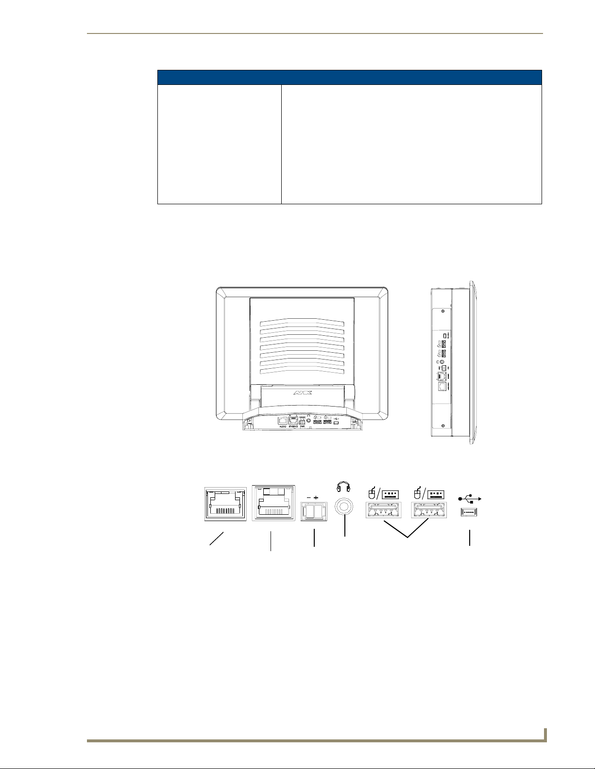
1200V-Series Modero Connectors
FIG. 2 shows the connectors on the 1200V Modero Video panels. The Audio/Video RJ-45 connector
provides differential audio/video signals between the touch panel and the NXA-AVB/ETHERNET.
This connector routes Composite video, Stereo (left/right) audio, and microphone audio.
NXT-1200V - connectors located
on rear panel of the base
A
ETHERNETAUDIO/VIDEO
Audio-Video from
NXA-AVB/ETHERNET
(CAT5)
Connector layout on sample 1200V Video Touch Panels
FIG. 2
Ethernet
(CAT5)
L
Power
12VDC
PWR
Stereo
Output
NXD-1200V - connectors located
on left side panel
PROGRAM
Keyboard/Mouse
USB connectors (2)
Mini-USB
(Program Port)
Cleaning the Touch Overlay
You should clean the touch screen overlay after each day’s use. Always use clean cotton cloths and a
spray bottle containing water.
1200V Modero Video Touch Panels
5
Page 16

Introduction
Connecting and Using Input Devices
The 1200V panel can have up to two USB-capable input devices connected for use on its different
firmware and TPD4 panel pages. These input devices can consist of a keyboard or mouse.
USB-connected input devices are not detected and recognized by the panel until
power is cycled to the unit.
A mini-USB connection is only detected after it is installed onto an active
panel. Connection to a previously powered panel, allows the PC to detect the
panel and assign an appropriate USB driver.
1. Insert the input device USB connectors into the appropriate USB connector on the panel.
2. Press the on-screen Reboot button from the Protected Setup page to save any changes and restart
the panel.
3. After the panel splash-screen disappears:
If a USB mouse has been connected, a mouse cursor appears on the panel screen and its
location corresponds to the mouse cursor position sent by the external USB mouse.
If a USB keyboard has been connected, only on-screen keyboards and keypads will reflect any external
keystrokes sent from the external USB keyboard.
6
1200V Modero Video Touch Panels
Page 17
Touch Panel Accessories
The following section outlines and describes both the included accessories and other AMX equipment
available for these touch panels.
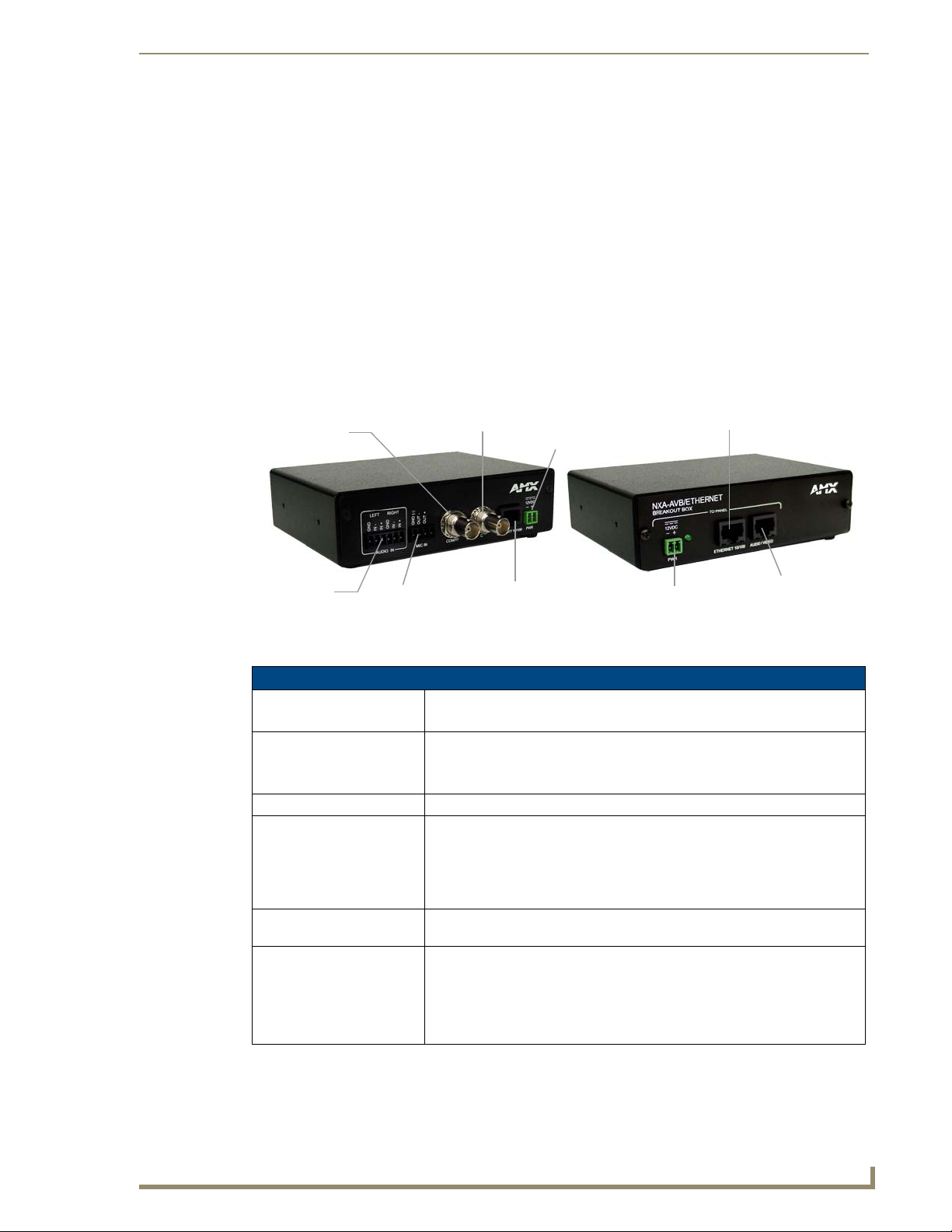
NXA-AVB/ETHERNET Breakout Box (FG2254-10)
The NXA-AVB/ETHERNET Breakout Box (FIG. 3) is included as part of the 1200V Kit configuration
(panel and box) but can be purchased as a separate accessory. This box facilitates the installation and
distribution of video, data, and audio to Modero touch panels located up to 200 feet (60.96 m) from the
AVB box. This unit accepts either Composite or S-Video from standard video devices.
This breakout box can be mounted on either a horizontal flat surface or in an equipment rack
(by using an optional AC-RK Rack Kit).
Touch Panel Accessories
Composite/
S-Video
(rear)
FIG. 3 NXA-AVB/ETHERNET Breakout Box (front and rear views)
Luma
Audio
In
Mic Out
S-Video Chroma
Power In
Ethernet In
Power (to panel)
Ethernet (to panel)
Audio/Video
(to panel)
Product Specifications
NXA-AVB/ETHERNET Specifications
Dimensions (HWD): • 1.50" x 5.55" x 4.88" (3.81 cm x 14.10 cm x 12.40 cm)
• Width when attached to mounting ears: 6.65" (16.89 cm)
Power Consumption: • 50mA (with audio/video input)
• 23mA (with no audio/video)
• Routed through NXA-AVB/Ethernet using a 12 VDC-compliant power supply
Certifications: • FCC Part 15 Class B, CE, and EN 60950
Features: • Accepts either Composite or S-Video (video-capable panels only)
• Provides audio distribution to the non-video touch panels over a CAT5 cable
(up to 200 ft.)
• Provides video/audio distribution to the video-capable touch panels over
CAT5 cable up to 200 ft. (60.9 m)
Availability: • This unit is included with CV5, CV7, CV10, and 1200V-Series Kit
Front Components: • 2-pin 3.5 mm Phoenix connector for power to the touch panel
configurations
• Green LED provides an indication of power status
• RJ-45 connector provides Ethernet signals to the touch panel
• RJ-45 connector provides differential audio and video signals to the touch
panel (panel type dependant)
(front)
1200V Modero Video Touch Panels
7
Page 18
Touch Panel Accessories
NXA-AVB/ETHERNET Specifications (Cont.)
Rear Components: • 6-pin 3.5 mm Phoenix connector for in-bound (left/right channel) audio
Included Accessories: • Two 2-pin Phoenix connectors (41-5025)
Other AMX Equipment: • AC-RK Accessory RackMount Kit (FG515)
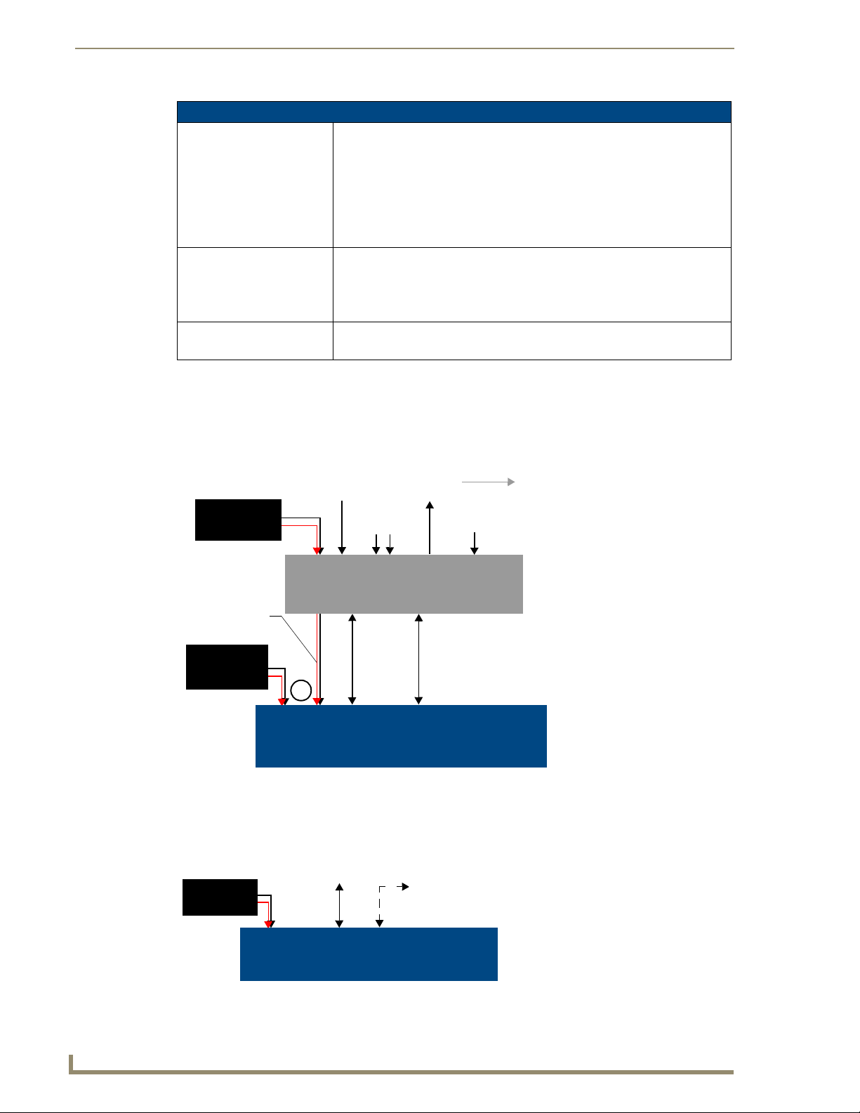
Installing the NXA-AVB/ETHERNET
A 12 VDC-compliant power supply can indirectly provide power to a Modero panel by routing power
through the NXA-AVB/ETHERNET Breakout Box. FIG. 4 shows a sample wiring configuration using
both an indirect or direct power connection for a video-capable Modero panel.
• 4-pin 3.5 mm Phoenix connector for out-bound (from microphone) audio
• BNC connector (female) for Composite or Chroma (for video-capable
panels only)
• BNC connector (female) for luminance (for video-capable panels only)
• RJ-45 connector for Ethernet input from the control system
• 2-pin 3.5 mm Phoenix connector for in-bound power
• 4-pin Phoenix connector (41-5047)
• 6-pin Phoenix connector (41-5063)
• Rack Mount Kit (KA2250-40) with mounting bracket (62-2254-02)
• Modero Table Top Cable (CA2250-50)
Indirect
Connect
12 VDC power
supply
Ethernet In
(RJ-45)
Video In
Mic Out
(4-pin captive-wire)
(BNC)
Audio In
(6-pin captive-wire)
Line Level out
(to amplifier
or VOL card)
(rear)
NXA-AVB/ETHERNET
Breakout Box
Power
supplied via
NXA-AVB box
12 VDC power
supply
Direct
Connect
or
Ethernet
(CAT5)
Audio/Video
(CAT5)
(front)
NXD/T Video-capable
Touch Panels
Sample wiring configuration on video-capable panels using this breakout box
FIG. 4
A 12 VDC-compliant power supply can also directly provide power through the unit to a target Modero
panel. FIG. 5 shows a sample wiring configuration for a non-video capable Modero panel.
Direct
connect
12 VDC power
supply
Ethernet
(CAT5)
Audio (CAT5)
between the
NXA-AVB/ETHERNET
Breakout Box
NXD/T Non-video capable
Touch Panels
FIG. 5 Sample wiring configuration using CA Modero panels
8
1200V Modero Video Touch Panels
Page 19
Touch Panel Accessories
The breakout box unit can be mounted on either a horizontal flat surface or into an
equipment rack (by removing the front screws and attaching it to an optional AC-RK).
The power supply being used on the NXA-AVB/ETHERNET is dependant on the
power requirements of the target touch panel.
Use a standard CAT5 Ethernet cable to provide both communication and 10/100 network connectivity
between the panel, NXA-AVB/ETHERNET, NetLinx Master, and the network.
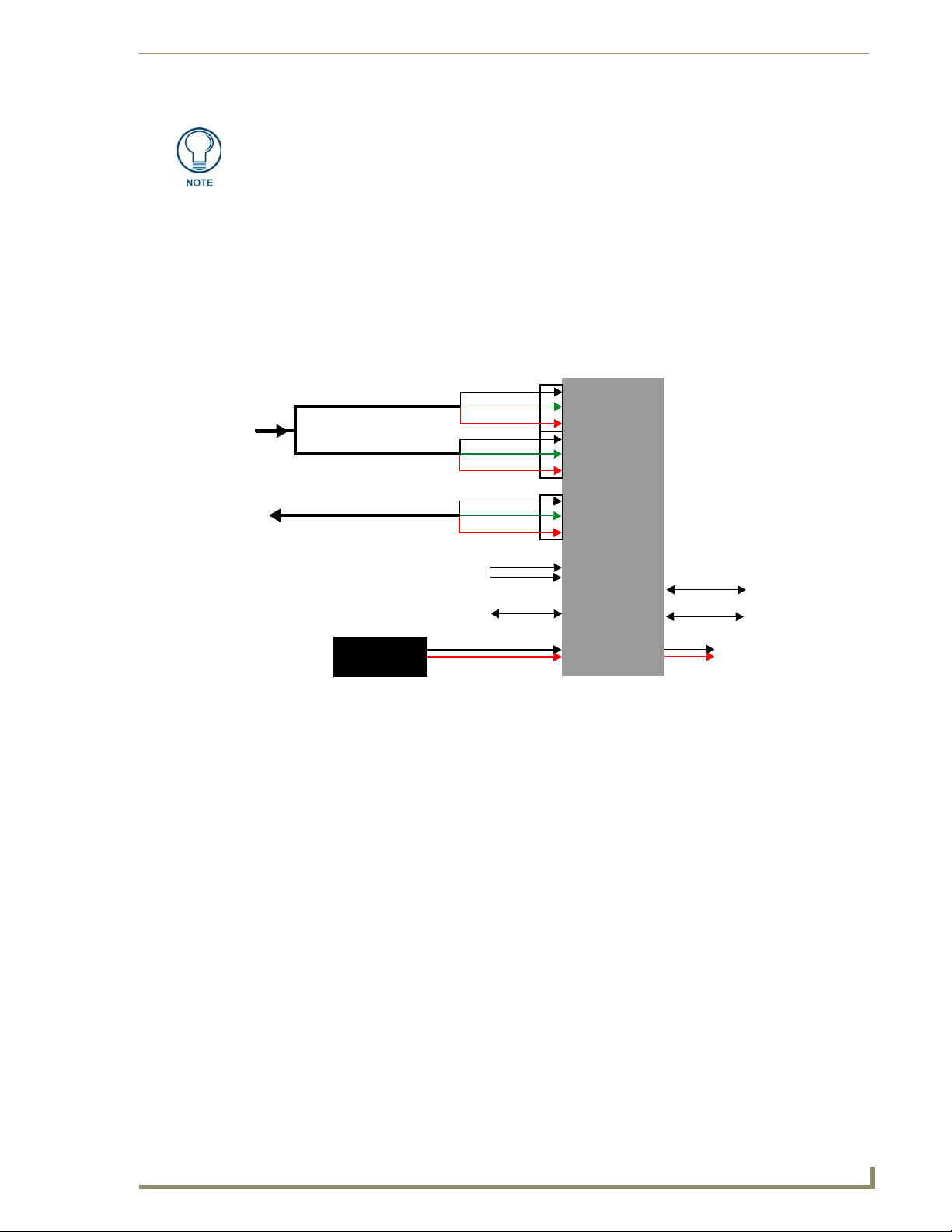
Wiring the NXA-AVB/ETHERNET connectors and cables
The inputs and outputs on the breakout box are separated into front and rear connectors. The rear
connectors are used to input external signals. The front connectors are used to communicate signals
between the NXA-AVB/ETHERNET and a target Modero panel. FIG. 6 provides a layout of the wiring
connection both into and from the breakout box.
Audio In - Left Channel
(6-pin captive wire)
Audio In - Right Channel
(6-pin captive wire)
GND
In (-)
In (+)
GND
In (-)
In (+)
F
R
O
N
T
NXA-AVB/ETHERNET
Breakout Box
Microphone Out
(4-pin captive wire)
GND(-)
Out (-)
Out (+)
Comp/Y (BNC)
C (BNC)
Ethernet
(RJ-45)
R
E
12 VDC power
supply
A
R
FIG. 6 NXA-AVB/ETHERNET Breakout Box connector wiring diagram
The rear-panel wiring connections are described below (from left to right):
• AUDIO IN: 6-pin mini-Phoenix connector, divided into left and right audio channels. Each
channel is divided into GND, IN+, and IN- terminal cable connectors
(2 sets of 3 for each channel).
An example of this cable is to strip the ends of 2 RCA audio cables and insert
them into their respective locations on the Audio In port.
Either a balanced (+, -, and GND) or unbalanced (+ and GND) audio
signal can be connected to this input.
• MIC OUT: 4-pin mini-Phoenix connector, divided into GND, OUT-, and OUT+ terminal
• Video In BNCs: Feeds either Composite/S-Video Luma or S-Video Chroma signals into the
• ETHERNET: RJ-45 connector routes data to the G4 touch panel through the front Ethernet
connectors.
An example of this cable is to strip the terminal ends of a 3.5mm mini-jack and
insert them into their respective locations on the Mic Out port. This signal can
be fed as a Line Level In to either an amplifier or an AMX VOL card.
Either a balanced (+, -, and GND) or unbalanced (+ and GND) audio signal
can be connected to this output.
NXA-AVB/ETHERNET. This feed is then redirected out to a Modero panel
through the front Audio/Video CAT5 port.
port. These connections use a standard CAT5 Ethernet cable to provide
communication between the target touch panel, breakout box, and NetLinx
Master.
Audio/Video
(CAT5)
Ethernet Out
(CAT5)
Power to
touch panel
1200V Modero Video Touch Panels
9
Page 20
Touch Panel Accessories
Wiring the NXA-AVB/ETHERNET for Unbalanced Audio
Most domestic audio equipment has unbalanced audio inputs and outputs. This means that the audio
output (left, right, or mono) appears on a single wire, and is referenced to "0 V" or "Ground". Typical
connectors used are RCA "phono" connectors, DIN plugs/sockets, and 0.25" (6.3mm) or 3.5mm jack
plugs/sockets.
Unbalanced audio is adequate for most domestic environments and for line-level signals in a typical
broadcast studio. Problems may occur if the signals are carried over long distances, especially if the
source and destination have separate main supplies. Use the following wiring drawing (FIG. 7) to
configure an unbalanced audio connection.
•PWR: 2-pin mini-Phoenix connector that connects to a 12 VDC-compliant power
supply. This port can be used to provide power to a Modero panel by sending it
through the NXA-AVB/ETHERNET (rear power connector through to the front
power connector).
GND
IN-
IN+
GND
IN-
IN+
AUDIO IN
MIC OUT
GND
OUT-
OUT+
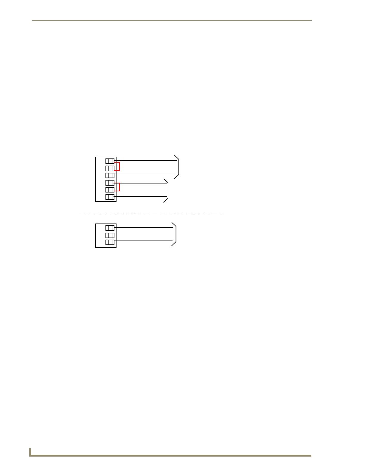
Wiring the rear AUDIO IN and MIC OUT for use with Unbalanced Audio
FIG. 7
Left Channel
Right Channel
Microphone
Unbalanced IN
(Jumper IN- to GND)
Unbalanced IN
(Jumper IN- to GND)
Unbalanced OUT
When using unbalanced audio for the AUDIO IN connector (FIG. 7), the "-" and the "GND" terminals
should be connected together and then connected to the GND of the unbalance audio signal. When
connecting to an unbalanced audio input from the MIC OUT connector (FIG. 7), wire the "+" terminal to
the signal input, and the "GND" terminal to the signal ground.
Wiring the NXA-AVB/ETHERNET for Balanced Audio
Professional audio equipment will often use balanced audio inputs and outputs, usually on 3-pin "XLR"
connectors. A balanced audio signal consists of a pair of wires carrying the audio signal in anti-phase
with each other (if one wire carries a positive voltage, the other carries an equal and opposite negative
voltage).
The advantage of balanced audio over unbalanced audio is its ability to reject external interference added
as the signal is carried over the wire. The receiving equipment takes the voltage difference between the
two wires as the input signal. Interference will usually get added to both wires equally, and so gets
cancelled by the receiving equipment.
10
1200V Modero Video Touch Panels
Page 21
Touch Panel Accessories
The 3 wires used in a typical XLR lead are often referred to as Ground, Live (Hot) and Return (Cold).
"Live" and "Return" carry the "in-phase" and "out-of-phase" versions of the audio respectively. The pins
of the XLR plug/socket are as follows:
• X = Ground
• L = Live (Hot)
• R = Return (Cold)
When connecting the MIC OUT connector to a balanced audio input (FIG. 8), use all three audio
terminals (+, -, and GND), then connect the "+" terminal to the "live" signal, the "-" terminal to the
"return" signal, and the "GND" terminal to the ground signal.
GND
OUT-
OUT+
Wiring the rear MIC OUT connector for use with Balanced Audio
FIG. 8
Ground signal
Return signal
Line signal
Balanced OUT
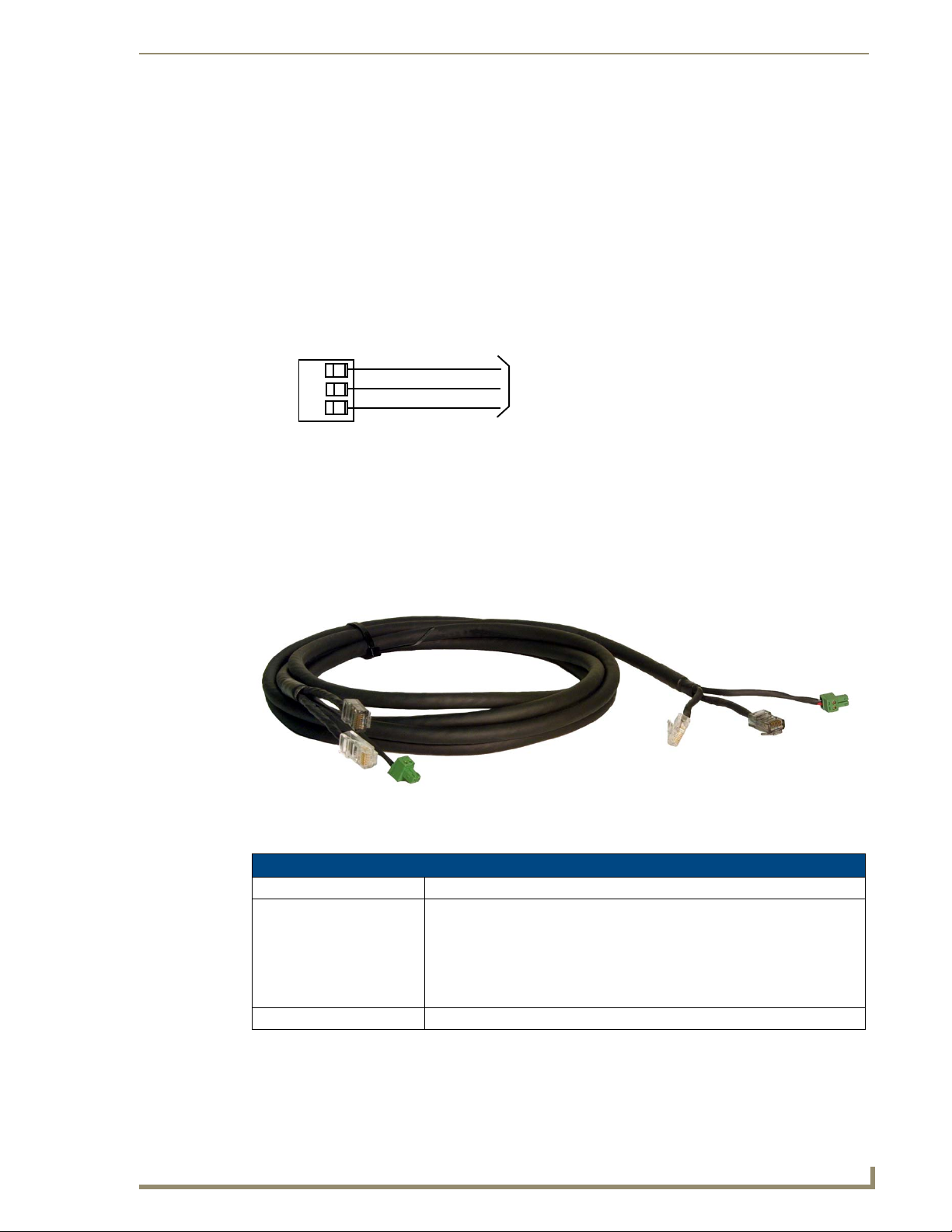
Modero Table Top Cable (CA2250-50)
The Modero Table Top Touch Panels come with a standard 10' (3.048 m) Modero cable
(CA2250-50) that supports Ethernet, Audio/Video, and Power connections. The cable comes terminated
with two RJ45 connectors (Ethernet and Audio/Video) and a single 2-pin mini-Phoenix connector for
power.
FIG. 9 10 Foot Modero Table Top Cable
Product Specifications
Modero Table Top Cable Specifications
Dimensions (HWD): • Length: 10 feet (3.048 m)
Connectors: • Ethernet RJ-45 connector (White) routes Ethernet signals between the touch
Included Accessories: • Modero Table Top Cable (CA2250-50)
1200V Modero Video Touch Panels
panel and the NXA-AVB/ETHERNET Breakout Box.
• Audio/Video RJ-45 connector (Black) routes differential audio/video signals
between the touch panel and the box.
• 2-pin 3.5 mm mini-Phoenix power connector to route power from the external
breakout box to the target panel.
11
Page 22

Touch Panel Accessories
Modero Table Top Cable Specifications (Cont.)
Other AMX Equipment: Note: All 1200V, VG-Series, and CV10 Table Top panels routing an
Audio/Video signal from a breakout box must use the appropriate number of
CAT5 Suppression Ferrites which are included as part of installation kits
accompanying your particular Modero panel.
Each of the following Installation Kits come with the appropriate number of
CAT5 Suppression Ferrites.
These ferrites must be installed onto their appropriate locations.
• Installation Kit for 12" and 17" NXD panels (KA2251-01):
- 2-pin mini-Phoenix connector (41-5025)
- Three Phillips-head screws (#4-20 x 0.250 Black) (80-0114-08)
- One CAT5 Suppression Ferrite (04-0014)
- Four Drywall clips (62-5924-05) and #6 -metal strips (80-0192)
• Installation Kit for 15" NXD panels (KA2251-02):
- 2-pin mini-Phoenix connector (41-5025)
- Three Phillips-head screws (#4-20 x 0.250 Black) (80-0114-08)
- Two CAT5 Suppression Ferrites (04-0014)
- Four Drywall clips (62-5924-05) and #6 -metal strips (80-0192)
• Installation Kit for 12" NXT panels (KA2251-03):
- 2-pin mini-Phoenix connector (41-5025)
- Three Phillips-head screws (#4-20 x 0.250 Black) (80-0114-08)
- Two CAT5 Suppression Ferrites (04-0014)
• Installation Kit for 15" and 17" NXT panels (KA2251-04):
- 2-pin mini-Phoenix connector (41-5025)
- Three Phillips-head screws (#4-20 x 0.250 Black) (80-0114-08)
- One CAT5 Suppression Ferrite (04-0014)
• Installation Kit for 10" NXT panels (KA2259-01):
- 2-pin 3.5 mm mini-Phoenix connector (41-5025)
- One CAT5 Table Top Suppression Ferrite (04-0014)
- One cylindrical CAT5 USB Mouse Suppression Ferrite (04-0018-SA)
Wiring information for the Modero Table Top cable
If your installation requires custom cable configurations, you can purchase bulk (non-terminated) cable
from Liberty Wire and Cable under the nomenclature "AMX Table Top Cable - Modero" (phone#:
(800) 530 8998 or +1-719-388-7518). When building a custom Table Top cable, please refer to the table
below to calculate the maximum length of the cable for your particular installation/setup.
Maximum Table Top Cable Lengths for Modero Panels
Panel Sizes: 7" Panel 10" Panel 12" Panel 15" Panel 17" Panel
Setup I: Using a panel without a battery base*:
Maximum cable length 150’ (45.72 m) 150’ (45.72 m) 49’ (14.94 m) 39’ (11.89 m) 10’ (3.05 m)
Setup II: Using a panel with a battery base*:
Maximum cable length 56’ (17.07 m) 56’ (17.07 m) 25’ (7.62 m) 15’ (4.57 m) 10’ (3.05 m)
* The total Modero cable run from the 13.5 V power source.
* The total Modero cable run from the 13.5 V power source (12 VDC-compliant power supply).
12
1200V Modero Video Touch Panels
Page 23
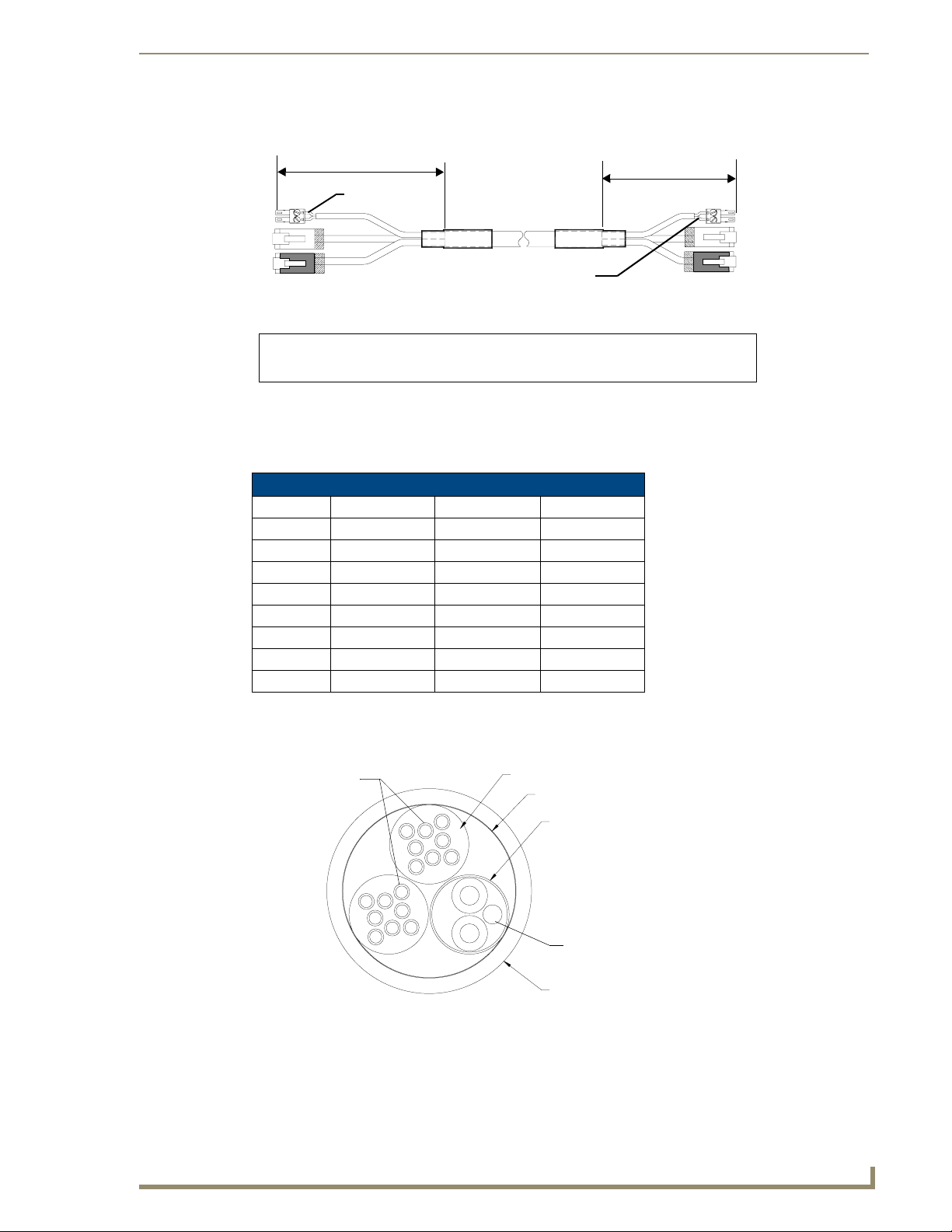
FIG. 10 shows the top and cross-section views of the Table Top cable.
Touch Panel Accessories
6 inches
Red
3
2
1
To Touch Panel To Breakout Box
Connector
Connector
FIG. 10 Modero Table Top cable (top and cross-section views)
1
- used for Audio/Video (Black)
2
- used for Ethernet (White)
Red
Connector 3 - used for Power
3 inches
3
2
1
The following table provides the wiring information (color coding) for each of the three available cable
connectors on each side of the Modero Table Top Cable.
Modero Table Top Cable Wiring Table
Wire Connector 1 Con ne ct or 2 Connector 3
1 White/Orange White/Orange Red
2 Orange/White Orange/White Black
3 White/Green White/Green -
4 Blue/White Blue/White -
5 White/Blue White/Blue -
6 Green/White Green/White -
7 White/Brown White/Brown -
8 Brown/White Brown/White -
The following figures provide a cross-section view (FIG. 11) and a description (FIG. 12) of the Modero
Table Top Cable:
Connector #1 & 2
FIG. 11
Table Top Cable - cross-section view
Element #1
Binder
Element #2
Connector #3
Jacket
1200V Modero Video Touch Panels
13
Page 24
Touch Panel Accessories
DESCRIPTION:
ELEMENT #1:
CONDUCTOR:
INSULATION:
COLOR CODE:
PAIR:
CABLE:
BINDER:
ELEMENT #2:
CONDUCTOR:
INSULATION:
COLOR CODE:
DRAIN WIRE:
SHIELD:
FINAL ASSEMBLY:
BINDER:
JACKET:
COLOR:
DIAMETER:
9/PAIRS COMPOSITE CABLE CONSISTING OF: ELEMENT #1:
TWO 4/PAIR 24 AWG STRANDED TINNED COPPER,
POLYETHYLENE INSULATION, ELEMENT #2: 1/PAIR 18 AWG
STRANDED TNNED COPPER, PVC INSULATION AND FOIL
SHIELDED OVERALL PAPER BINDER AND FLEX-PVC JACKET.
2 X 4/PAIRS: 24 AWG STRANDED COPPER
24 AWG 7/32 TINNED COPPER; OD .024" NOMINAL
.0075" WALL POLYETHYLENE; OD .039" NOMINAL
P1: WHITE/BLUE, BLUE
P2: WHITE/ORANGE, ORANGE
P3: WHITE/GREEN, GREEN
P4: WHITE/BROWN, BROWN
2 CONDUCTORS TWINNED LEFT HAND LAY
(TWISTED AT VARIED LAYS TO MINIMIZE CROSS TALK)
4/P CABLED LEFT HAND LAY (BLUE BINDER, ORANGE BINDER)
PAPER TAPE
1 PAIR: 18 AWG SHIELDED
18 AWG 16/30 TINNED COPPER; OD .046" NOMINAL
.010" WALL PVC; OD .066" NOMINAL
BLACK, RED
#22 7/30 TINNED COPPER
ALUM/POLYESTER TAPE (FOIL SIDE IN)
TWO ELEMENT #1 & ELEMENT #2 CABLED ON COMMON
AXIS TO MINIMIZE DIAMETER
CLOTH TAPE 25% OVERLAP
.045" WALL FLEXIBLE PVC,
BLACK MATT
.375 INCHES NOMINAL
NONEMARKING:
FIG. 12 Table Top Cable - Specification Elements
Each bundle of 4 twisted pairs includes a colored tape indicator for identification.
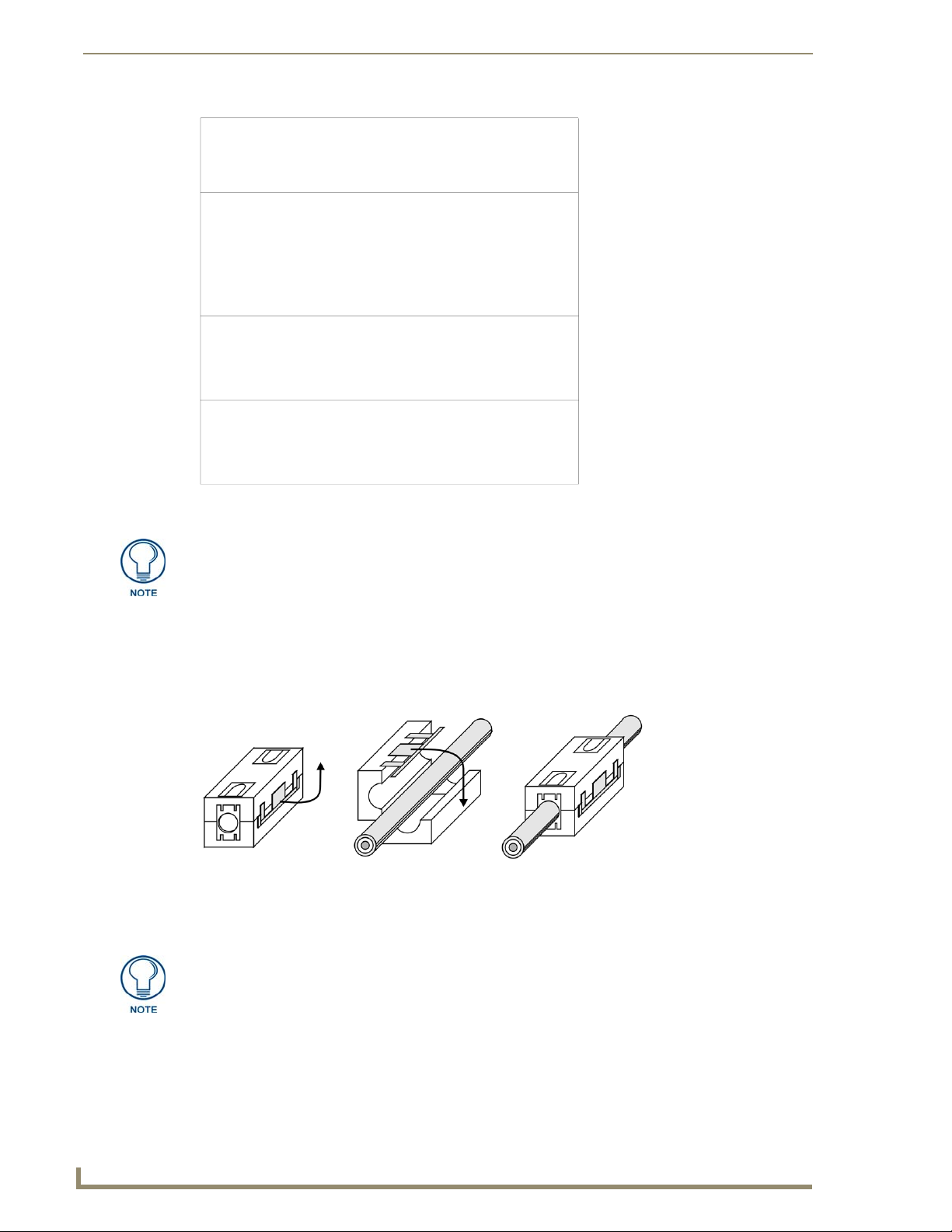
Installing CAT5 Suppression Ferrites
Before connecting the RJ-45 cables to the panel, install the necessary number of CAT5 Suppression
Ferrites (FIG. 13) to their appropriate locations. These ferrites come as part of the Installation Kits
mentioned in the previous Specification table (page 2). No tools are required for this installation.
Release the latch to
open the plastic
enclosure.
FIG. 13 Installing the CAT5 Suppression Ferrites
Insert the CAT5
cable and close
the enclosure.
Push down on the
enclosure until it
snaps closed.
All 1200V-Series, VG-Series, and Table Top CV10 panels require the installation of
an appropriate number of CAT5 Suppression Ferrites when they use an RJ-45 cable
to feed an A/V signal from the breakout box.
1. The CAT5 Suppression Ferrite is housed within a plastic enclosure (shown in FIG. 12) with a latch
release on one side. Pull to release the latch and open the enclosure.
14
1200V Modero Video Touch Panels
Page 25
Touch Panel Accessories
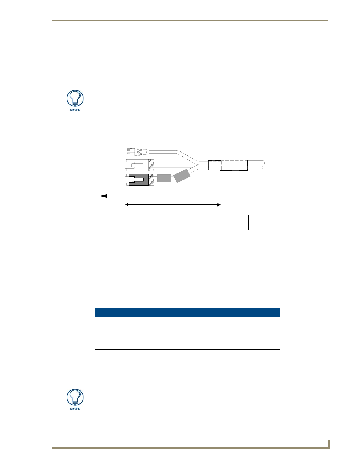
2. Grasp the Black RJ-45 Audio/Video cable being connected to the panel. This end of the cable is
longer than the opposing end which connects to the breakout box (6 inches vs 3 inches). Refer to
FIG. 14 for more detailed information.
3. Insert the panel-end of the Black RJ-45 Audio/Video cable into the groove along the inside of the
enclosure.
The CAT5 Suppression Ferrites MUST be installed onto the cable connected to the
Modero’s Audio/Video RJ-45 connector (just behind the connector).
4. Snap the enclosure shut with the cable inside, and you’re done.
5. Repeat this process again only when installing an additional CAT5 Suppression Ferrite
(model specific).
3
2
e
t
i
r
r
e
F
To To u ch
Panel
1
Ferrite
6 inches
Connector
FIG. 14 Ferrite connector location on Audio/Video RJ-45 cable
2
- used for Ethernet (White)
Connector 3 - used for PowerConnector 1 - used for Audio/Video (Black)
NXA-CFTP Compact Flash (FG2116-2x)
Every Modero panel is shipped with two factory default modules: an EXM Memory Module and a
Compact Flash card. These panels are shipped with a 256 memory module which is not
upgradeable.
The default 128 MB Compact Flash card is factory programmed with specific panel firmware and is the
only upgradeable memory component. This component can be ordered from AMX in several different
upgrade sizes (as listed in the following table):
Optional Compact Flash Memory Upgrades
Compact Flash:
NXA-CFTP256M - 256 MB Compact Flash card (FG2116-23)
NXA-CFTP512M - 512 MB Compact Flash card (FG2116-24)
NXA-CFTP1G - 1 GB Compact Flash card (FG2116-25)
Upgrading the internal components involves opening the panel enclosure/outer housing to access the
internal circuit board, removing the existing part, and replacing them with the upgrade components, as
described in the following sections.
It is recommended that any upgrade of internal equipment be done simultaneously in
order to reduce the risk of damage to internal components.
1200V Modero Video Touch Panels
15
Page 26
Touch Panel Accessories
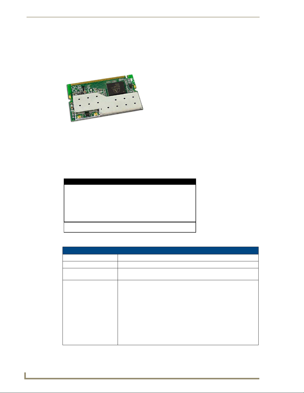
NXA-PCI80211G Wireless Card (FG2255-04)
The 1200V-Series and VG-Series Modero touch panels can connect to an internal NXA-PCI80211G
compatible mini-PCI Wireless Card connected to two antennas (57-2250-10). All 1200-V and VG-Series
panels come factory installed only with the two antennas used for later connection to the optional
wireless card which is field-installable.
FIG. 15 NXA-PCI80211G mini-PCI Wireless Card
The NXA-PCI80211G card functions using a 2.4GHz bandwidth with a maximum data transfer rate of
54Mbps. This card is compatible with IEEE 802.11 standards such as: 802.11b and 802.11g.
The NXA-80211G allows the end-user to take advantage of larger bandwidth to utilize features such as:
wireless intercom, Motion JPEG, networked video, and standard wireless Ethernet communication to
both a NetLinx controller and networked computers. Please follow your particular Wireless Access
Point’s instruction manual for the correct procedures to setup either a secured or unsecured connection.
FCC Statement:
This device complies with Part 15 of the FCC rules. Subject to the following two conditions:
1. This device must not cause harmful interference and
2. This device must accept all interference, including interference that interferes with the
operation of this device.
Modifications not expressly approved by the manufacturer will void the user’s authority
to operate the equipment.
WARNING: This device has been evaluated and found to be compliant w ith the FCC Ru les
for RF Exposure when the device is operated at a minimum separation distance from the
user and nearby persons. Operation of this device at closer distances should be avoided.
Certifications: FCCID: CWU-WN2301A, CE, EN 60950, EN 300 328,
and RSS 210
Product Specifications
NXA-PCI80211G Specifications
Dimensions (HWD): • 0.02" x 2.13" x 4.66" (5.0 mm x 54.0 mm x 118.4 mm)
Weight: • 1.05 oz (30g)
Description: • Direct Sequence Spread Spectrum (DSSS)/CCK 802.11g Wireless mini-PCI
card with detachable antennas.
Features: • Contains integrated power amplifier (PA) and low-noise amplifier (LNA)
• Diversity Antenna Connectors automatically select the best available signal
• Enhanced transmit and receive chains
• Field-installable
• Increased sensitivity and multipath tolerance
• Operates from 2.300-2.500 GHz
• Operate at ISM frequency bands (2.4GHz) with 54Mbps data rate
• Pre-configured to communicate with current AMX Wireless Access Points
• Support for IEEE 802.11b and 802.11g
• Wired Equivalent Privacy (WEP) 64-bit and 128-bit data encryption
16
1200V Modero Video Touch Panels
Page 27
Touch Panel Accessories
NXA-PCI80211G Specifications (Cont.)
Antenna Type: • Dual antenna connector
Availability: • All 1200V-Series and VG-Series NXT Table Top panels come factory
Bus Interface: • mini-PCI card, TypeIIIB
Certifications: • FCCID: CWU-WN2301A, CE, EN 60950, EN 300 328, and RSS 210and
Frequency Range: • Using 802.11b & g communication:
Media Access Technique: • CSMA/CA with ACK
Modulation: • Orthogonal Frequency Division Multiplexing (OFDM) / Complementary Code
Network Architecture: • Ad-hoc mode (Peer-to-Peer)
Network Standard: • IEEE Compliant
Operating Channels: • Using 802.11b & g communication:
Operating Environment: • Temperature: 0°C ~ 55°C (32°F to 131°F) (operating) and
Operating Voltage: •3.3V +
Power Consumption: • @ 802.11b communication:
Radio Data Rate: • 802.11g compliant: 1, 2, 5.5, 11 (DSSS/CCK); 6, 9, 12, 18, 24, 36, 48, and 54
configured for wireless communication. These NXT panels are all factory
installed with both the NXA-80211G wireless mini-PCI and 2 antennas.
• Optional to the following NXD panels:
- NXD-1200V
- NXD-1200VG
- NXD-1500VG
- NXD-1700VG
FCCID (CWU-WN2301A)
- 2.412 ~ 2.462 GHz - North America
- 2.412 ~ 2.484 GHz - Japan
- 2.412 ~ 2.472 GHz - Europe ETSI
- 2.457 ~ 2.462 GHz - Spain
- 2.457 ~ 2.472 GHz - France
Keying (CCK)
• Infrastructure mode
• 802.11b and 802.11g
- 11: (Ch 1 - 11) - North America
- 14: (Ch 1 - 14) - Japan
- 13: (Ch 1 - 13) - Europe ETSI
- 2: (Ch 10 - 11) - Spain
- 4: (Ch 10 - 13) - France
-20°C ~ 70°C (-4°F to 158°F) (storage)
• Humidity: (non-condensing) 5% ~ 90% RH (operating) and
(non-condensing) 5% ~ 95% RH (storage)
5% I/O supply voltage
- RX: 300 mA
- TX: 64 mA
- Sleep: 12mA
• @ 802.11g communication:
- RX: 330 mA
- TX: 575 mA
- Sleep: 12mA
(OFDM) Mbps data rates
1200V Modero Video Touch Panels
17
Page 28
Touch Panel Accessories
NXA-PCI80211G Specifications (Cont.)
Receiver Sensitivity: • Using 802.11b communication:
Security: • 64-bit and 128-bit WEP
Availability: • All 1200V-Series and VG-Series NXT Table Top panels can be field upgraded
Installation and Upgrade of the Internal NXT Components
1 Mbps: -86 dBm (max)
2 Mbps: -84 dBm (max)
5.5 Mbps: -83 dBm (max)
11 Mbps: -80 dBm (max)
• Using 802.11g communication:
1 Mbps: -86 dBm (max)
2 Mbps: -84 dBm (max)
5.5 Mbps: -83 dBm (max)
11 Mbps: -80 dBm (max)
for wireless communication using the optional NXA-PCI80211G mini-PCI
card.
• Optional to the following NXD panels:
- NXD-1200V
- NXD-1200VG
- NXD-1500VG
- NXD-1700VG
Upgrading the components within the Table Top panel involves removing the outer housing (with
speaker plate), removing and/or installing an existing component, and then placing the outer housing
back onto the NXT panel, as described in the following sections.
Do not use Ethernet cables containing mounting boots. These boots could make
removal of the Ethernet connectors (from the panel) difficult and cumbersome.
Step 1: Remove the existing NXT Outer Housing
Carefully detach all connectors from the rear of the touch panel and then gently place the touch
1.
panel LCD facedown onto a soft cloth to expose the under-side of the base (FIG. 16). This step
helps prevent scratching of the LCD.
2. Tilt the base forward so that both the bottom surface and Housing Screws are easily accessible and
then carefully remove the four plastic adhesive feet.
Reference the location of the four plastic adhesive "feet". Once the outer housing is
placed back onto the panel, these "feet" must be placed back in their original
locations so they can fit into their provided openings on a Battery Base.
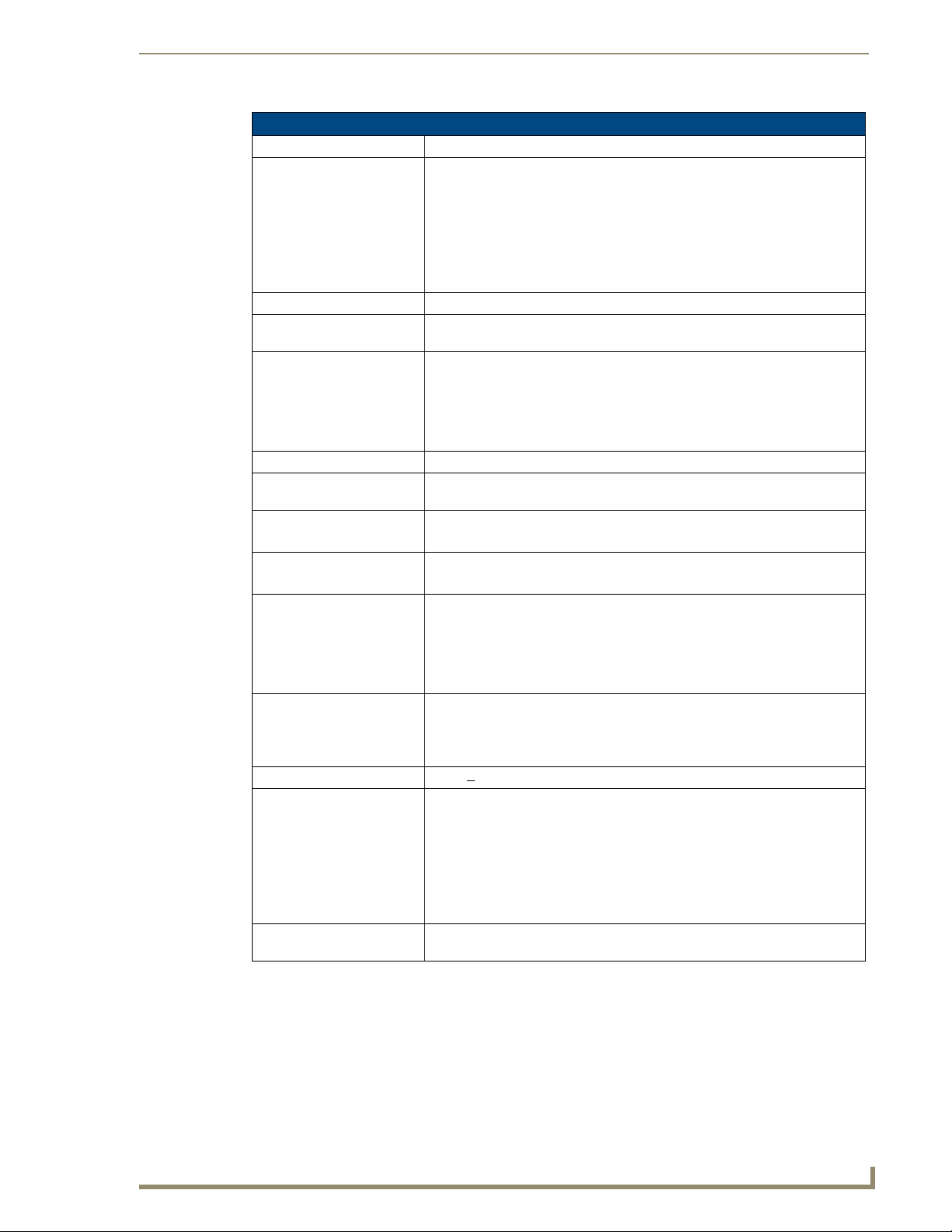
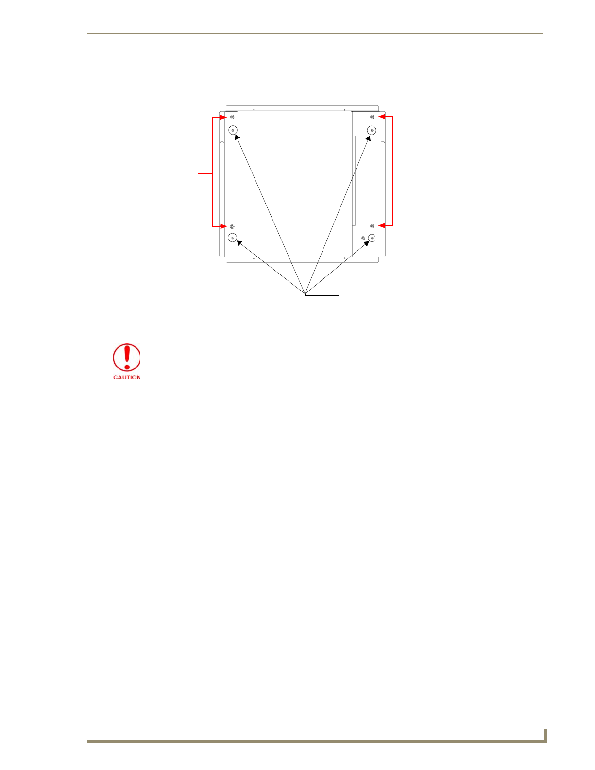
3. While holding the outer housing and base plate at a 45° (to prevent it from sliding), use a grounded
Phillips-head screwdriver to remove the eight Housing Screws.
18
1200V Modero Video Touch Panels
Page 29
Touch Panel Accessories
Base plate
Unscrew these
eight Housing
Screws to remove
the circuit board
housing
DO NOT
REMOVE
these screws
They secure
the speakers
to the main
board
FIG. 16 Location of the attachment screws underneath an NXT panel base
Outer housing
45°
Hinge Brackets (2)
4. Rotate the panel back over (while gripping the entire unit with outer housing) and rest the base on a
flat surface.
5. Gently tilt the LCD backward to a 45° angle.
6. In a single motion, carefully pull the outer housing up and then out (away from the LCD panel) to
expose the internal circuit board.
7. Unscrew the Stereo Output nut from the Stereo Output jack.
8. Firmly grab the existing connector plate and slide it up and away from the base.
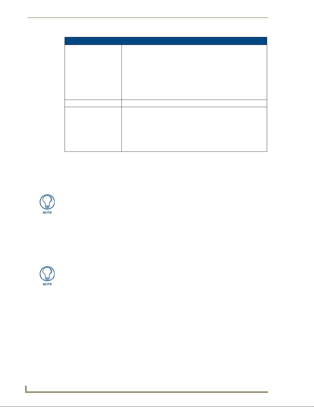
Step 2: Install the 802.11g mini-PCI Wireless Card
Discharge any static electricity from your body by touching a grounded metal object.
1.
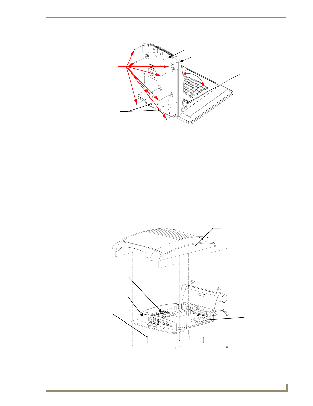
2. Locate the mini-PCI card connector on the main board (FIG. 17 and FIG. 18).
Outer Housing
NXA-PCI80211G
wireless card
location
I/O connector
Eight Housing
Screws
plate
Compact Flash card
FIG. 17 Location of the NXA-PCI80211G wireless card on the NXT board
1200V Modero Video Touch Panels
19
Page 30
Touch Panel Accessories
FIG. 18 Location of the mini-PCI card connector on main board
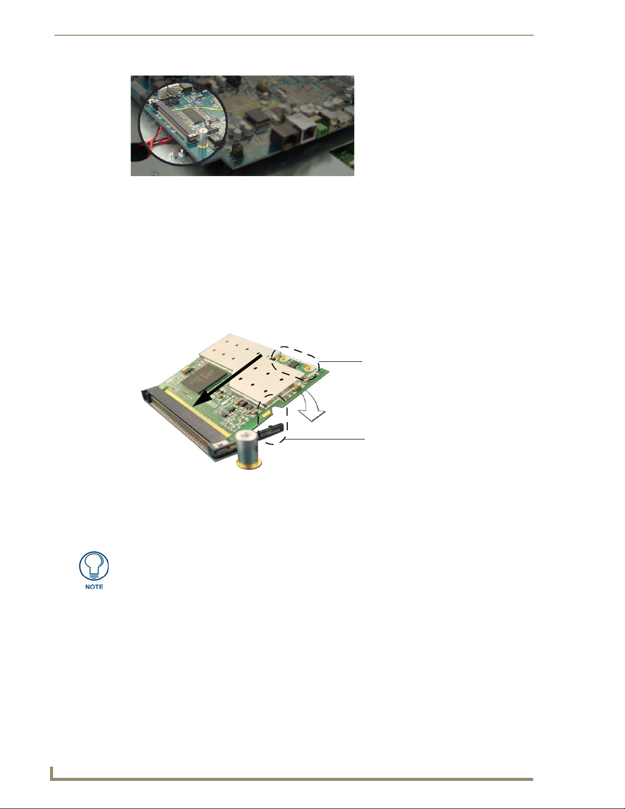
3. Carefully remove the gold-tipped terminal ends of the antenna from their factory default connectors
4. Firmly grasp the NXA-PCI80211G mini-PCI card (from the edges) and insert the pins (at a 25°
5. While maintaining the 25° angle alignment on the new module, push it in firmly until the contact
6. Push the card downward (to the main board) until the side braces snap atop the NXA-PCI80211G
on the main board. The antenna is secured at this location to restrict its movement prior to
connection to a wireless card.
angle) into the opening on the connector (FIG. 19).
pins are completely inside the connector and the card "snaps" into place (FIG. 19).
and hold it in place.
Antennas connectors
Connection point
between the braces and
the mini-PCI card
FIG. 19 Installation of the mini-PCI card connector on main board
7. Locate the terminal ends of the antennas and apply downward pressure to "snap" them onto their
gold-tipped counterparts on the mini-PCI card (FIG. 19). Carefully push down on each connector to
verify it is securely joined to the card.
It is recommended that any upgrade of internal equipment be done simultaneously in
order to reduce the risk of damage to internal components.
20
1200V Modero Video Touch Panels
Page 31

Touch Panel Accessories
Step 3: Install the Compact Flash Memory Card upgrade
1.
Discharge any static electricity from your body by touching a grounded metal object and then locate
the existing Compact Flash card (factory-shipped with 128 MB) on the main board (FIG. 20 for
Table Top panels and FIG. 23 for Wall Mount panels).
Outer Housing
NXA-PCI80211G
wireless card
I/O connector
Eight Housing
Screws
FIG. 20 Location of the Compact Flash card and I/O plate on NXT
plate
Compact Flash card
2. Insert the tip of a grounded flat-head screwdriver into one of the card removal grooves (located on
either side of the existing card), and gently pry the card out of the slot (FIG. 21). Repeat this process
on the opposite card removal groove. This alternating action causes the card to "wiggle" away from
the on-board connector pins.
Card removal
grooves
On-board Compact
Flash connector (with pins)
Insert with arrow
facing towards the pins
FIG. 21 Removing/installing a Compact Flash Memory card
3. Grip the old card by its sides and then carefully pull it out of the slot.
4. Remove the new CF memory card from it’s anti-static bag.
1200V Modero Video Touch Panels
Connector opening
21
Page 32

Touch Panel Accessories
5. Grip the sides of the new CF memory card and firmly insert it into the slot opening (with the arrow
6. To complete the upgrade process, close and resecure the panel enclosure using the procedures in the
Any new internal card upgrade is detected by the panel only after power is cycled.
Step 4: Close and Resecure the NXT Panel Enclosure
1.
2. Resecure the Stereo Output nut back onto the new Stereo Output jack onto the I/O plate.
3. With the components securely installed, tilt the LCD back to a 45° and gently slide-on the outer
4. Gently press down on the housing (toward the base) until it is securely positioned over the circuit
facing towards the pins) until the contact pins are completely inside the flash card and it is then
securely attached to the pin sockets.
following step.
Obtain the I/O connector plate and slide it back into position (FIG. 20).
housing (towards the LCD) until the it is aligned over the installation holes and the tilt bracket
prevents any further forward movement (FIG. 16).
board and covers base.
Use caution when re-installing the outer housing. Improper re-installation can cause
damage to the internal speakers.
5. While holding the outer housing and base plate in place, turn the panel back over until the LCD lies
facedown on a soft cloth and the under-side of the base is exposed.
6. Insert and secure the eight Housing Screws (using a grounded Phillips-head screwdriver) into their
respective locations (FIG. 16).
7. Replace any adhesive plastic "feet" that might have been removed during the removal process of the
outer housing. These "feet" must be placed back onto their original locations so they can fit into
their provided openings on the Battery Base.
8. Grasp both the LCD and housing and then rotate the entire unit back onto a flat surface.
9. Insert all connectors and apply power.
Installation and Upgrade of the Internal NXD Components
Upgrading the components within a WallMount panel involves removing the rear plastic outer housing
(back box), removing and/or installing an existing component, and then placing the back box back onto
the NXD panel, as described in the following sections.
Step 1: Remove the existing NXD Outer Housing
1.
Carefully detach all connectors from the side of the touch panel and remove the front magnetic
faceplate from the NXD unit by firmly gripping the faceplate and pulling outwards, while applying
a small amount of pressure to remove it from the main unit.
2. Place the LCD facedown onto a soft cloth to expose the under-side of the unit (FIG. 22). This step
helps prevent scratching of the LCD.
3. Unscrew the Stereo Output nut from the Stereo Output jack.
22
1200V Modero Video Touch Panels
Page 33
Touch Panel Accessories
4. Remove the I/O connector plate by using a grounded Phillips-head screwdriver to remove the two
screws and slide the I/O connector plate away from the back box housing.
DO NOT
REMOVE
these
panel
securing
screws
Unscrew these four Housing Screws
to remove the back box. These make direct
contact with the black outer housing.
FIG. 22 Location of the securing screws on an NXD panel
DO NOT REMOVE
these panel
securing screws
DO NOT REMOVE THE PANEL SECURING SCREWS. These screws secure the
LCD to the metallic casing.
5. Unscrew the four pan-head Housing Screws from the rear of the NXD unit (FIG. 22) and gently
remove the outer housing. These four screws secure the back box to the internal panel casing.
Step 2: Install the new 802.11g mini-PCI Wireless card (NXD)
1.
Complete the procedures outline within Step 2: Install the 802.11g mini-PCI Wireless Card section
on page 19 and then continue with the following step.
Step 3: Install the new Compact Flash Memory card (NXD)
Complete the procedures outline within Step 3: Install the Compact Flash Memory Card
1.
upgrade section on page 21 and then continue with the following step.
1200V Modero Video Touch Panels
23
Page 34

Touch Panel Accessories
Four Pan-head
Housing
Screws
NXA-PCI80211G
wireless card
location
FIG. 23 Location of the Compact Flash card and I/O plate on NXD
Outer Housing
I/O connector
plate
Compact Flash card
Step 4: Close and Resecure the NXD Panel Enclosure
1.
With the components securely installed, gently place the outer housing back onto the metallic panel
casing (with the connector opening on the right-side of the panel) and align the four pan-head
Housing Screw holes along the edges of the outer housing.
Use care not to bend or damage any antenna connections while replacing the outer
housing.
2. Insert and secure the four pan-head Housing Screws into the pre-drilled holes along the edges of the
NXD unit by using a grounded Phillips-head screwdriver.
3. Reinstall the I/O connector plate by aligning all connectors to their respective locations.
4. Secure the I/O connector plate using a grounded Phillips-head screwdriver and then twist the Stereo
Output nut back into the Stereo Output jack.
24
1200V Modero Video Touch Panels
Page 35

Touch Panel Accessories
NXT-BP Power Pack (FG2255-10)
The NXT-BP Power Pack (FIG. 24) is a rechargeable Lithium-Ion "smart" battery used to provide power
to the NXT Modero panel through the NXA-BASE/B Battery Base. This battery incorporates an
on-board battery life indicator. The NXT-BP battery can be charged through either the base (when
connected to the Modero panel) or through an optional NXT-CHG Modero Power Station.
Extra NXT-BP Power Packs can be purchased separately as an optional accessory.
FIG. 24 NXT-BP Power Pack
Product Specifications
NXT-BP Specifications
Dimensions (HWD): • 0.69" x 3.50" x 5.81" (1.75 cm x 8.89 cm x 14.76 cm)
Power (Voltage): • 11.1 Volts (nominal)
Weight: • Single NXT-BP Power Pack: 1.0 lbs (0.45 kg)
Features: • Battery Usage: 4 to 8 hours (time is usage dependant)
• Charge Capacity: 6300mAh
Operating / Storage
Environment:
• Operating Temperature: 0° C (32° F) to 40° C (104° F)
• Operating Humidity: 20% - 85% RH
• Storage/Discharge Temperature: -20° C (-4° F) to 60° C (140° F)
• Storage Humidity: 5% - 85% RH
NXA-BASE/B Battery Base Kit (FG2255K)
The NXA-BASE/B Battery Base is a Modero accessory that allows the Modero Table Top touch panels
(NXT) to function off the collective charge of two internally connected NXT-BP batteries (FG2255-10).
The base provides both power and battery information to the panel via the panel interface connector
(FIG. 25). The NXT-BP batteries can be charged through either the base (only when connected to the
NXT touch panel) or through an optional NXT-CHG Modero Power Station.
Panel Interface
Connector
NXA-BASE/B
Battery Base
FIG. 25
1200V Modero Video Touch Panels
NXA-BASE/B and NXT-BP combo
NXT-BP
Battery Pack
25
Page 36

Touch Panel Accessories
This base also comes as part of a NXA-BASE/B Kit that contains one (1) battery base and two batteries.
The accompanying batteries can be charged through either the base or optional NXT-CHG Battery
Charger (FG2250-50). Refer to the Installing the NXA-BASE/B to an NXT Modero Panel section on
page 27 for more detailed installation and usage instructions.
Product Specifications
NXA-BASE/B Specifications
Dimensions (HWD): • 1.13" x 8.63" x 11.81" (2.86 cm x 21.91 cm x 30.00 cm)
Power Requirements: • 2.7 A @ 12 VDC (max power draw while charging)
Weight: • Base unit: 1.25 lbs (0.567 kg)
Features: • Charge time for two depleted batteries ~ 5 - 8 hours (when NXT panel is in
Operating / Storage
Environment:
Other AMX Equipment: • NXT-CHG Kit (FG2250-50K):
• Base and 2 batteries: 3.23 lbs (1.47 kg)
Sleep mode)
• Must be connected to the Modero unit utilizing a 12 VDC-compliant power
supply
• Operating Temperature: 0° C (32° F) to 40° C (104° F)
• Operating Humidity: 20% - 85% RH
• Storage Temperature: -20° C (-4° F) to 60° C (140° F)
• Storage Humidity: 5% - 85% RH
Charger (FG2250-50) and 2 NXT-BP batteries (FG2255-10)
• NXT-BP battery pack (FG2255-10)
• NXT-CHG battery charger (FG2250-50)
It is recommended to fully charge the batteries before their initial use.
Checking the NXT-BP battery charge
Press the Battery Life Indicator button (FIG. 26) once to illuminate the Battery Life LEDs and
1.
display the percent charge remaining on the battery (this indication lasts a few seconds).
Battery Life (Charge) Display
Battery Life Indicator button
FIG. 26 NXT-BP (showing Battery Life Indicator button and charge)
2. Repeat the above step for each NXT-BP battery.
3. Charge the NXT-BP battery by either inserting it into the battery base or from within the optional
NXT-CHG charger (which can sequentially charge up to two batteries).
If the 25% LED is blinking, this indicates there is less than 5% of a charge remaining
on the battery.
26
1200V Modero Video Touch Panels
Page 37

Touch Panel Accessories
Installing the NXA-BASE/B to an NXT Modero Panel
The battery base must be installed onto the NXT panel without any NXT-BP batteries.
1. Power Off the panel before attempting to use the NXA-BASE/B.
2. Place the empty battery base onto a flat/level surface.
3. Verify the alignment of the Panel Interface connectors between the panel (male connector) and base
(female connector) (FIG. 27).
Battery Compartment
pulls outwards
Alignment
pegs
FIG. 27 NXA-BASE/B showing Panel Interface and connector locations
Captive fasteners
(secure base to
panel)
Panel Interface
connector (female)
4. Carefully place the Modero panel over the base alignment pegs (FIG. 27 and FIG. 28).
The battery base cannot be "hot-swapped". A panel receiving power through a
connected 12 VDC-compliant power supply cannot have a battery base installed onto
the bottom of the panel while powered. POWER OFF the panel before installing the
NXA-BASE/B.
"Hot swapping" could damage the base and cause it not to be recognized by the
panel.
5. Gently apply downward pressure until the panel is securely mounted to the battery base (FIG. 28).
6. Firmly grip both the panel (from the side) and battery base (from below) together.
7. Gently place the touch panel LCD facedown onto a soft cloth (this prevents scratching of the LCD
while the battery base is being secured).
8. Locate the captive fasteners on the underside of the battery base by angling the base combo slightly
forwards.
9. Secure each captive fastener head using a grounded flat-head screwdriver until the NXA-BASE/B is
securely attached to the underside of the NXT Modero touch panel.
10. Firmly grip the panel LCD/base combo and gently rotate the unit back onto the base.
1200V Modero Video Touch Panels
27
Page 38
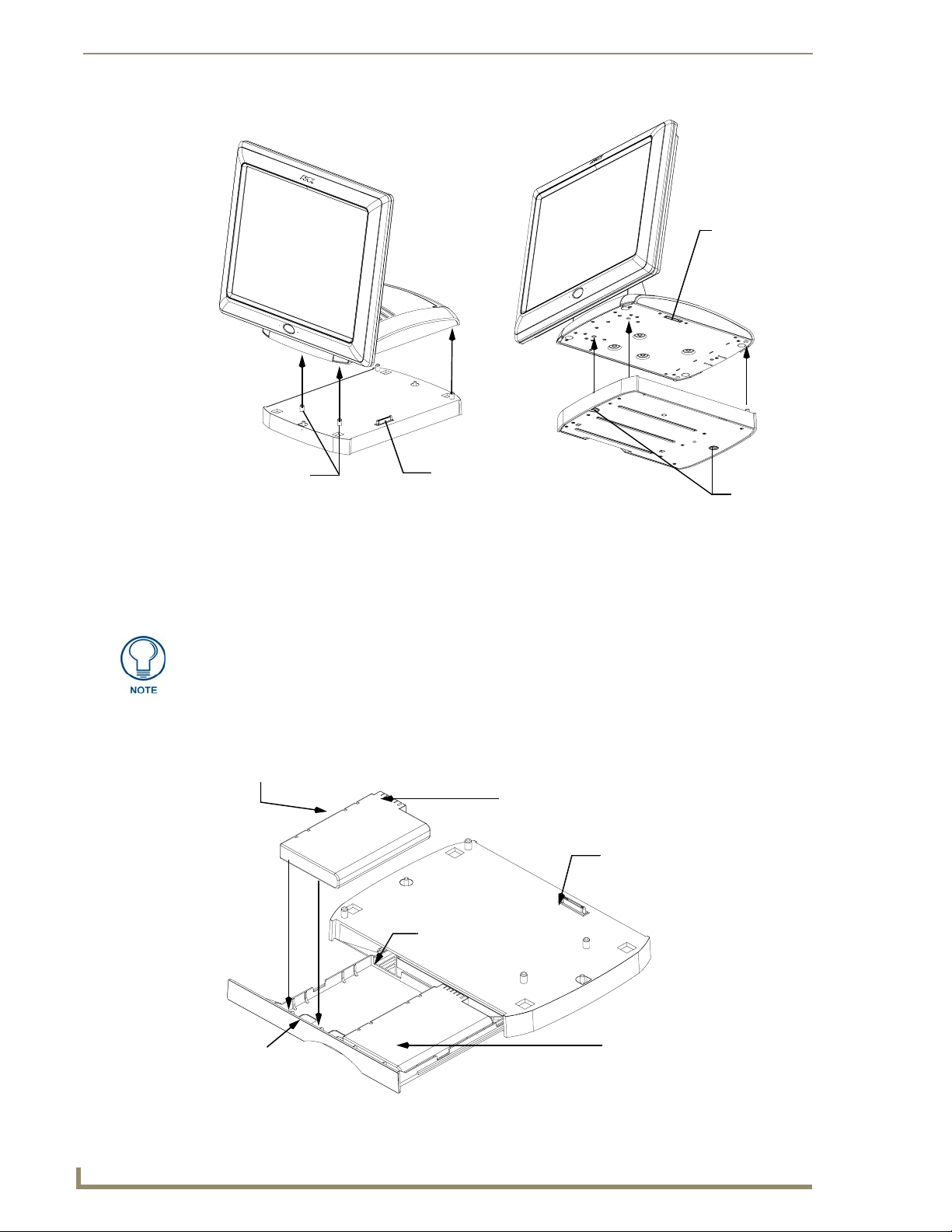
Touch Panel Accessories
Top view
Alignment
pegs
FIG. 28 NXA-BASE/B shown aligning with NXT panel
Panel Interface
connector
(female)
Bottom view
Interface
connector
(male)
Captive
fasteners
Installing an NXT-BP into the NXA-BASE/B
The battery base does not directly connect to a power supply, but rather receives its power directly from
the Modero panel, through the Panel Interface connector.
Remove any connectors from the rear of the Modero NXT panel before continuing
with the installation of the batteries. Power can only be supplied after the batteries
have been installed.
1. With the panel mounted on the battery base, open the battery compartment (FIG. 29) by pulling the
handle outwards. This compartment houses two NXT-BP batteries.
NXT-BP Battery #2
Battery
Connectors
Interface
connector
Battery
Connector
Por t
Battery #2
slot
Battery
Compartment
FRONT
NXT-BP Battery #1
28
FIG. 29 Battery installation procedure
1200V Modero Video Touch Panels
Page 39

Touch Panel Accessories
2. Install the NXT-BP battery. label-side down.
3. Align the battery connectors with the corresponding battery connector port (located inside the
battery compartment), as shown in FIG. 29.
4. Insert the NXT-BP battery until the connectors securely fit into the battery connector port.
5. Repeat steps 2 through 4 for the other battery.
6. Apply a small amount of pressure to close the battery compartment until the compartment latches.
After a few seconds, the panel will turn On and the AMX logo will appear (indicating the
panel is receiving power.
Charging the NXT-BP batteries with the NXA-BASE/B
1.
Follow the procedures from the previous sub-section to attach the NXT touch panel to the
NXA-BASE/B.
2. Insert each battery into the battery compartment shown in FIG. 29.
3. Insert a 2-pin connector from a power supply to the rear PWR connector on the NXT Modero panel.
The charge status bargraph indicators, on the Battery Base page, indicate when the batteries
are fully charged.
The NXA-BASE/B will only charge batteries when the NXT panel is in Sleep mode.
NXT-CHG Battery Charger Kit (FG2255-50K)
The NXT-CHG Kit includes one charger and two batteries. The optional NXT-CHG Modero Power
Station (FIG. 30) is a two-slot, stand-alone battery charger that can be used to recharge up to two
NXT-BP batteries. The batteries are charged in the order they are inserted into the charger. The
NXT-CHG Slot 1 has the feature of being able to completely discharge and recharge (recalibrate) a
battery.
Battery Life indicator
NXT-BP Modero Power Pack (battery)
NXT-CHG Modero Power Station (charger)
FIG. 30 NXT-CHG Kit (consists of one NXT-CHG charger and two NXT-BP batteries)
1200V Modero Video Touch Panels
29
Page 40

Touch Panel Accessories
Product Specifications
NXT-BP and NXT-CHG Specifications
Dimensions (HWD): • 1.13" x 8.63" x 11.81" (2.86 cm x 21.91 cm x 30.00 cm)
Power Requirements: • NXT-BP Battery Voltage - 11.1 Volts
Weight: • 0.57 lbs (0.26 kg)
Features: • Charge time for two depleted batteries: ~ 5 hours
Other AMX Equipment: • NXT-CHG Kit (FG2250-50K):
• NXT-CHG: 90 - 264 VAC, 47-63 Hz, Single Phase
(using the included 24 VDC power supply)
• Charge Rate: 2.5 A @ 12 VDC
• 2-Bays: Sequential charging
• LED: One LED indicator in front of each bay which conveys the status of that
bay. Refer to the Reading NXT-CHG LED Indicator section for more
information.
• Recalibration pushbutton (located between the bays): Initiates recalibration
sequence in the left bay only.
• Recalibration Time: less than 9 hours
- 1 charger and 2 NXT-BP batteries
• NXT-BP battery pack (FG2255-10) (additional)
The batteries are charged in the order they are inserted into the NXT-CHG. SLOT 1 of the
NXT-CHG has the ability to completely discharge and recharge (recalibrate) a battery.
Recalibration improves the reporting accuracy of the battery charge back to the
Modero panel.
Powering the NXT-CHG
The NXT-CHG Smart Battery Charger uses an included power supply to charge inserted batteries.
1. Connect the rear of the NXT-CHG to the power adapter.
2. Connect the power adapter to the provided power cord (with plug).
3. Provide power to the unit by connecting the power cord (with plug) into a power outlet that meets
the requirements outlined in the Specifications section for the NXT-CHG.
Reading NXT-CHG LED Indicator
FIG. 31 shows the components on the NXT-CHG Smart Battery Charger.
Slot 1
(recalibration)
Slot 2
30
Slot 1
LED
Slot 2
LED
Recalibrate
Pushbutton
FIG. 31 Component locations on the NXT-CHG
1200V Modero Video Touch Panels
Page 41

Touch Panel Accessories
There is one LED indicator on the front of each battery slot that indicates the status of that slot. The blink
patterns for these LEDs are described in the following table:
• Off: No battery detected.
• Green Flashing: Fast charging.
• Green Solid: Fully charged.
• Yellow Flashing: Recalibration in process.
• Yellow/Green: Recalibration complete.
• Yellow Solid: Standby (waiting for other battery to charge).
• Red Flash: Error (problem with either the battery connection to the internal slot, or with
the battery itself).
Charging the NXT-BP batteries using the NXT-CHG
Review the Checking the NXT-BP battery charge section on page 26 to confirm the percentage of
1.
charge remaining on the batteries.
2. Provide power to the charger (as outlined in the Powering the NXT-CHG section on page 30).
3. Align the battery connector with the corresponding charge slot within each of the two NXT-CHG
slots.
4. Firmly insert the battery into the desired slot until the battery is both securely located within the slot
and there is activity from the corresponding Slot LED. Refer to the Reading NXT-CHG LED
Indicator section on page 30 section for LED information.
Recalibrating the batteries
The recalibration process increases the accuracy of the battery charge level. Recalibration of the batteries
is only done upon request from the Modero on-screen Battery Base page. Refer to the Battery Base
Page section on page 102 for more detailed Battery Base page information.
Recalibration can only be done with Slot 1 on the NXT-CHG.
1. Place the selected battery securely into Slot 1 (left slot) until there is activity on the Slot 1 LED.
2. Push the Recalibration pushbutton (located between the two slots) to initiate recalibration in the
left bay only.
1200V Modero Video Touch Panels
31
Page 42

Touch Panel Accessories
32
1200V Modero Video Touch Panels
Page 43

Installation Procedures: NXD-1200V Panels
Installation Procedures: NXD-1200V Panels
NXT panels are mounted onto flat (horizontal) surfaces in either a stand-alone or combo (NXT atop an
NXA-BASE/B battery base) configuration. NXD panels are installed into either a pre-wall surface (using
a CB-TP12 conduit/wallbox) or a solid surface (using either solid surface or drywall screws).
It is recommended that if you are planning on upgrading your panel components
(flash card and wireless), you do so before beginning any panel installations.
Unpacking the Panel
1. Inspect and confirm the contents of the shipment box to verify that you have all specified parts.
Refer to the Specifications sections on page 2 for more information about included accessories and
other AMX equipment.
2. Carefully remove the panel from the shipping box.
3. Carefully peel the protective plastic cover from the LCD.
If the protective plastic LCD cover is not removed, the panel may not respond
properly to touch points on the LCD or allow proper screen calibration.
Installing the Internal Components
Installation of the internal components such as the upgraded Compact Flash memory and
NXA-PCI80211G Wireless card are described in detail within the following sections:
Step 2: Install the 802.11g mini-PCI Wireless Card section on page 19.
Step 3: Install the Compact Flash Memory Card upgrade section on page 21.
Upgrading to the MB-TP12 VESA Mounting Kit
Upgrading the existing back box with the new VESA Mounting Kit on the 12" (FG031-50) panel
requires 3 main processes:
Removing the pre-existing back box and installing the new VESA back box.
Threading cables through the strain relief grommet opening in the rear plastic cover.
Finalizing the installation of the NXD (with VESA back box and cables) into the plastic cover,
securing both components, and finalizing the strain relief grommet installation.
Only overall dimensions and FG product numbers are different.
The new MB-TP Universal VESA Mounting Box uses a standard VESA installation
pattern of 75 mm between holes. VESA mounts that conform to this pattern can be
used on the MB-TP Housing.
1200V Modero Video Touch Panels
33
Page 44

Installation Procedures: NXD-1200V Panels
Removing the Original Modero Back Box
1.
Detach all connectors from the side of the touch panel.
2. Remove the magnetic faceplate from the NXD unit by gripping the faceplate and pulling outwards
while applying a small amount of pressure to remove it from the main unit.
3. Place the LCD face-down on a soft cloth to expose the back of the panel and prevent scratching of
the LCD.
4. Unscrew the Stereo Output nut from the Stereo Output jack.
5. Remove the I/O connector plate by using a grounded Phillips-head screwdriver to remove the two
screws and slide the I/O connector plate away from the back box housing.
6. Remove the four pan-head Housing Screws from the rear of the NXD unit (FIG. 32). These screws
secure the back box to the internal panel casing.
DO NOT
REMOVE
these
panel
securing
screws
DO NOT REMOVE
these panel
securing screws
Unscrew these four Housing Screws
to remove the back box. These make direct
contact with the black outer housing.
FIG. 32 Location of the attachment screws on the NXD back box
DO NOT REMOVE THE FOUR PANEL SECURING SCREWS. These screws secure
the LCD to the metallic casing underneath.
7. Lift the back box housing to separate it from the internal panel casing.
Installing the MP-TP12 Back Box
1.
Unscrew the four pan-head Housing screws (#8-32) from the MP-TP12 rear plastic cover.
2. Gently place the MP-TP12 back box over the internal panel casing (with the cable routing hole on
the right-side of the panel).
3. Re-install and secure the four pan-head Housing Screws into their pre-drilled holes along the edges
of the MB-TP12 back box (FIG. 33) and secure them using a grounded Phillips-head screwdriver.
4. Place the I/O connector plate back over the connector opening and align the connector locations.
5. Resecure the I/O connector plate (using a grounded Phillips-head screwdriver) and resecure the
Stereo Output nut on the Stereo Output jack.
34
1200V Modero Video Touch Panels
Page 45
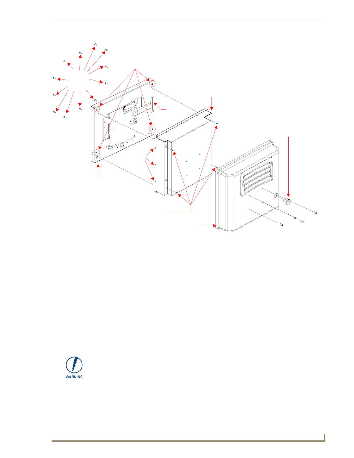
Tw el v e
#6-32
securing
screws
Internal panel casing
DO NOT REMOVE
Securing
hole locations
(3 on each side)
Connector
Opening
MB-TP12 back box
Installation Procedures: NXD-1200V Panels
Strain relief grommet
Rim of the strain relief grommet
should lie flush against enclosure
(Clip facing up)
Four (pan-head) Housing Screws
Rear plastic cover
FIG. 33 Location of the attachment screws on the NXD back box and VESA housing
Cable Installation for the MP-TP12 Back Box
Connect the cable connectors (RJ-45, Ethernet, and any other audio/video wiring) to their respective
1.
locations along the side of the touch panel.
2. Thread the incoming cables through the strain relief grommet opening on the rear plastic cover
(FIG. 33).
Finalizing the installation
Gently place the rear plastic cover over the NXD panel (with LCD and MB-TP12 back box).
1.
2. Insert the protruding cables, coming out from the opening on the rear plastic cover, into the open
strain relief grommet.
3. Allow some slack/length on these cables as a service loop. This service loop provides enough cable
length so you can later remove the NXD (with connected cables) from the rear plastic cover.
VERIFY THE LENGTH AND LOCATION OF THE INSERTED CABLES. ONCE THE
STRAIN RELIEF GROMMET IS CLOSED, IT IS DIFFICULT TO RE-OPEN.
Four (#8-32) screws
4. Carefully apply pressure to close the strain relief grommet over the desired cable location.
1200V Modero Video Touch Panels
35
Page 46
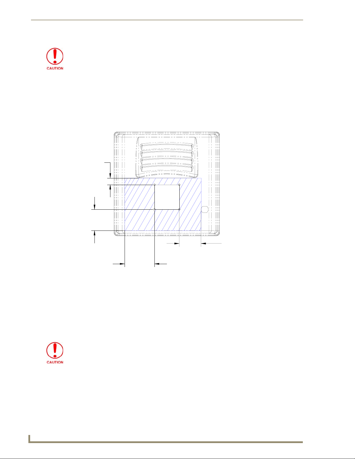
Installation Procedures: NXD-1200V Panels
Verify the Strain Relief Grommet is securely closed over the cables and the clip is
facing the correct direction (upwards). The process of securing the strain relief
grommet may require the use of pliers. Also verify the length and location of the
inserted cables. Once the strain relief grommet is closed, it is difficult to re-open.
5. Firmly push the Strain Relief Grommet into the opening (toward the inside) until the rim is securely
flush against the back of the rear plastic cover (FIG. 33).
6. Securely grasp both sides of the NXD panel (with LCD, MB-TP12 back box, and attached cables),
rotate the entire unit over, and lie it on a flat level surface.
7. Note the available mounting contact surface area on the rear plastic cover of the MB-TP12
(FIG. 34). This area represents the space available for use with a VESA connector plate.
.80[20MM]
2.52[64MM]
2.61[66MM]
3.55[90MM]
FIG. 34 MB-TP12 Mounting contact surface area
8. Insert and secure the twelve #6-32 securing screws into their pre-drilled holes along the edges of the
NXD unit (FIG. 33). This step secures the NXD unit to the rim of the rear plastic cover.
9. Align a VESA mount connector (purchased separately) to the four #8-32 screw holes on the back of
the rear plastic cover (FIG. 33).
10. Insert the four provided #8-32 screws through the VESA mount’s four holes and then into the
pre-drilled holes on the rear plastic cover.
When installing a VESA mount to the rear plastic cover, use only the AMX provided
#8-32 screws.
11. Secure these four #8-32 screws to the rear plastic cover by using a grounded Phillips-head
screwdriver. This step secures the VESA mount to the rear of the panel.
Refer to your particular VESA mount manufacturer’s installation procedures for further surface
mounting procedures.
36
1200V Modero Video Touch Panels
Page 47
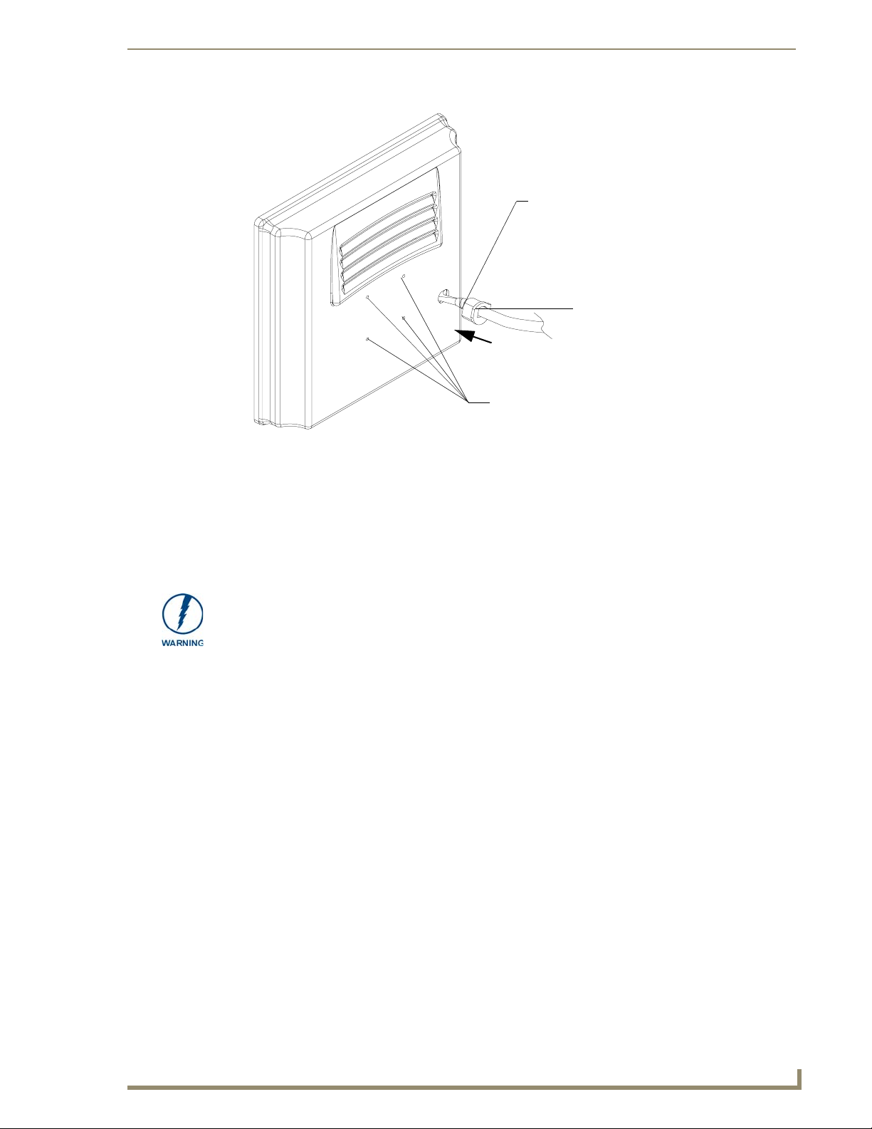
Rear plastic cover (rear view)
VESA mount connection location
(USE ONLY AMX PROVIDED #8-32 screws)
FIG. 35 Installation of grommet into the rear plastic enclosure
Installation Procedures: NXD-1200V Panels
Rim of the strain relief grommet
should lie flush against enclosure
CLIP FACING UP
Pre-wall Installation of the Conduit Box
Wall Mount panels (NXDs) are contained within a metallic outer housing (back box). This back box is
not removed when installing the NXD into a conduit box (CB-TP12). The back box is only removed to
either gain access for the replacement of the Memory/Compact Flash or upgrade the unit with an MB-TP
Universal VESA Mounting Kit.
INSTALLER: LEAVE A GAP BETWEEN THE STUD AND CONDUIT BOX TO
ACCOMMODATE THE DRYWALL SHEETROCK. This gap allows the installation of
the drywall/sheetrock after the conduit box has been installed.
The CB-TP12 conduit wallbox is an optional metallic box that is secured onto stud beams prior to the
installation of a solid surface. Installation procedures and configurations can vary. This section describes
the installation procedures for the most common installation scenario.
1. Fasten the CB-TP12 to a stud through the stud fastening holes, located on the inside of the conduit
box (FIG. 36), by using either nails or screws.
2. Remove any necessary wiring knockouts from the (optional) conduit box (C in FIG. 36) where the
necessary cables are threaded through for connection to the touch panel.
3. Thread the incoming RJ-45, Ethernet, and any other audio/video wiring through the knockouts.
Refer to the Wiring Guidelines for the 1200V Panels section on page 45 for pinout descriptions.
Leave enough slack in the wiring to accommodate any re-positioning of the panel.
4. Install the drywall/sheetrock before inserting the main NXD unit into the CB-TP12.
1200V Modero Video Touch Panels
37
Page 48

Installation Procedures: NXD-1200V Panels
Stud
Knockouts should be located on the left-side of the
conduit box, alongside the connectors
Drywall/
sheetrock
Mounting tabs
for NXD panel should
be flush with the outside of the sheetrock
FIG. 36 Screw locations for conduit box attachment in a pre-wall installation
CB-TP Conduit Wallbox
Stud fastening holes
Use the four #4-40
Mounting Screws to
secure the NXD to the
conduit box at these
locations
Installation of the NXD Touch Panel
The NXD panel can be installed either directly into the (optional) CB-TP12 or other solid surface
environment using the two different mounting options: drywall clips or solid surface screws. The
following sections describe mounting the touch panel directly into a pre-wall installed conduit box, a
solid surface or drywall, and optional NXA-RK Rack Mount Kit.
Installing the NXD panel within a Conduit Box
The conduit box must be mounted prior to continuing this section. Refer to the procedures in the
Pre-wall Installation of the Conduit Box section on page 37 for detailed pre-wall installation
instructions. Verify that all necessary cables have been threaded through the knockouts on the conduit
box and the connections have been tested prior to installation of the NXD panel.
1. Remove the magnetic faceplate/bezel (A in FIG. 37) from the main NXD unit (B in FIG. 37) by
gripping the faceplate and pulling with gentle outward force.
2. Verify the incoming RJ-45, Ethernet, USB, and any other audio/video cables have been properly
threaded through the wiring knockouts (from their terminal locations) on the conduit box.
Leave enough slack in the wiring to accommodate any re-positioning of the panel.
3. Connect all data and power wiring connectors to their corresponding locations along the side of the
(un-powered) NXD touch panel.
Verify the terminal end of the power cable is not connected to a power supply before plugging
in the 2-pin power connector.
The USB connectors can be from either a USB extension cable, or a wireless USB RF
transmitter.
4. Test the incoming wiring by connecting the panel connections to their terminal locations and
applying power. Verify the panel is receiving power and functioning properly to prevent repetition
of the installation.
5. Disconnect the terminal end of the power cable from the connected power supply.
38
1200V Modero Video Touch Panels
Page 49
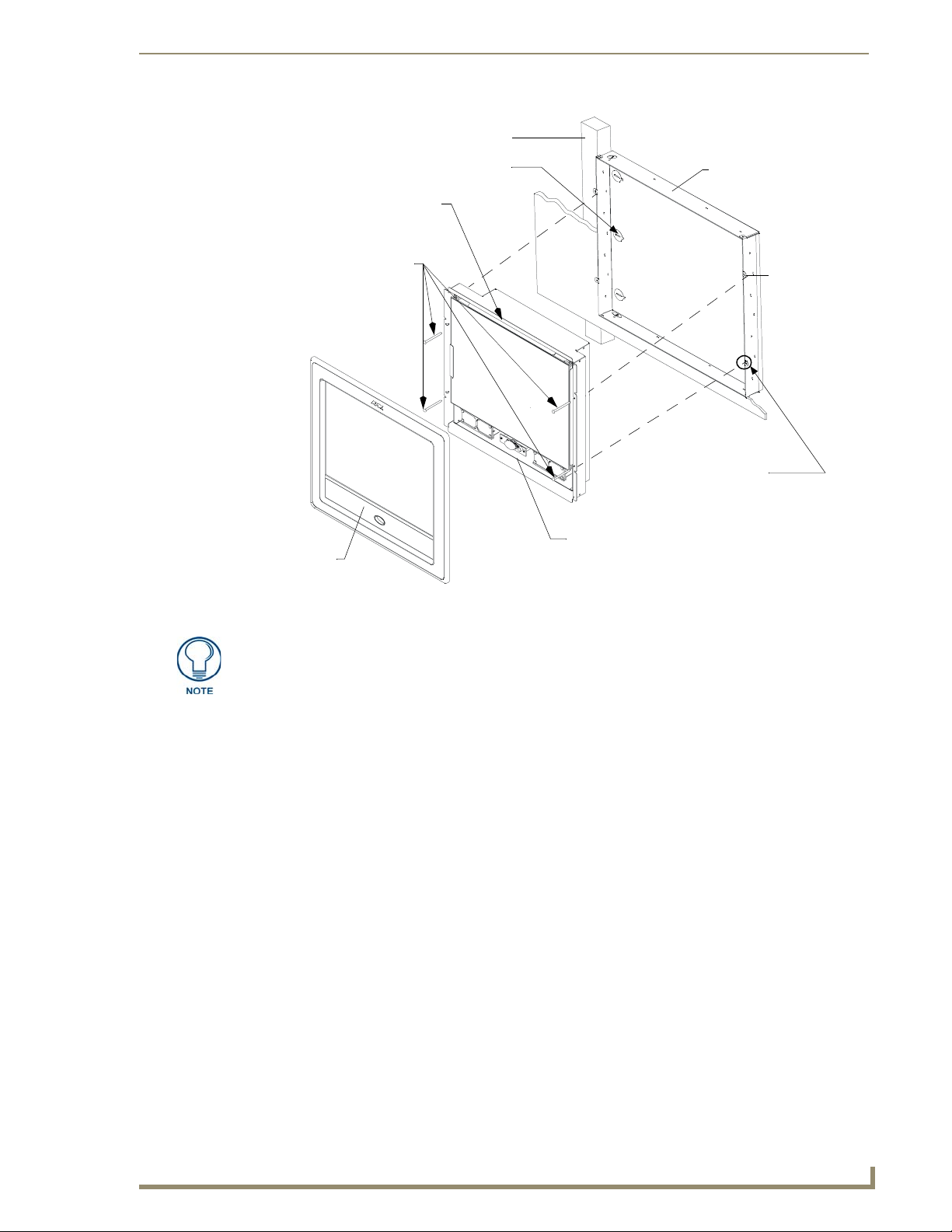
Mounting Tab
Stud
Cable
knockouts
Installation Procedures: NXD-1200V Panels
C - Optional CB-TP
conduit/wallbox
Install the four #4-40
screws into the places
A - Faceplate
(bezel)
FIG. 37 Wall Mount panel installation configuration for pre-existing conduit/wallbox in a pre-wall construction
indicated
SURFACE
Do not use these
tabs to mount
the conduit /wallbox
These are ONLY used to
secure the main unit to the CB
B - Main NXD unit consists of
the touch panel and backbox housing
Installed flush
against the
finished wall
surface
Don’t disconnect the connectors from the touch panel. The unit must be installed with
the attached connectors before being inserted into the conduit box.
6. Carefully slide the main unit (B in FIG. 37) into the conduit box, so the Mounting Tabs lie flush
against the conduit box (C in FIG. 37).
7. Insert and secure the four securing #4-40 Mounting Screws into their corresponding holes located
along the sides of the NXD (FIG. 36 and FIG. 37).
8. Place the magnetic faceplate (A in FIG. 37) back onto the main NXD unit (B in FIG. 37).
Make sure to align the Microphone, Light, and PIR Motion sensor locations to their respective
openings on the front bezel/faceplate.
9. Reconnect the terminal RJ-45, Ethernet, USB, and any optional audio/video wiring to their
respective locations (outside the conduit box) on either the NXA-AVB/ETHERNET Breakout Box,
Ethernet port, or NetLinx Master.
10. Reconnect the terminal power connector on the 12 VDC-compliant power supply and apply power.
1200V Modero Video Touch Panels
39
Page 50

Installation Procedures: NXD-1200V Panels
Installing the NXD into drywall using Expansion Clips
Expansion clips are mounted through the four oval holes located at the top and bottom of the panel. As
the screw is tightened, the clip bends toward the insertion hole and into the wall. This bending creates a
"grip" on the wall by either pressing onto the wall or by securing the drywall between the housing and
the drywall clip.
The most important thing to remember when mounting the NXD is that the outer frame (Mounting Tabs)
must be installed flush against the mounting surface.
1. Prepare the area by removing any screws or nails from the drywall before beginning the cutout
process.
2. Cut out the surface for the 12-inch Wall Mount using the dimensions shown in FIG. 38. Be sure to
cut out the four notches along the top and bottom areas to accommodate the four drywall expansion
clips (provided).
40
CUTOUT
FRONT BEZEL
FIG. 38 NXD-1200V 12-inch Wall Mount panel dimensions using expansion clips
3. Remove the magnetic faceplate/bezel (A in FIG. 39) from the main NXD unit (B in FIG. 39) by
gripping the faceplate and pulling with gentle outward force.
1200V Modero Video Touch Panels
Page 51

Install the four drywall
clip sets (included)
into these holes
Mounting Tab
Installation Procedures: NXD-1200V Panels
4 notches are
required if the
unit is installed in
drywall using the
four (4) provided
drywall expansion
clips
B - Main NXD unit consists of
A - Faceplate
(bezel)
FIG. 39 Wall Mount panel (NXD) installation configuration for drywall surfaces
the touch panel and housing
4. Thread the incoming RJ-45, Ethernet, USB, and any other audio/video wiring (from their terminal
locations) through the cutout opening. Refer to the Wiring Guidelines for the 1200V Panels section
on page 45 for pinout descriptions.
Leave enough slack in the wiring to accommodate any re-positioning of the panel.
5. Connect all data and power wiring connectors to their corresponding locations along the side of the
(un-powered) NXD touch panel.
Verify the terminal end of the power cable is not connected to a power supply before plugging
in the 2-pin power connector.
The USB connectors can be from a either a USB extension cable, or a wireless USB RF
transmitter.
6. Test the incoming wiring by attaching the panel connections to their terminal locations and applying
power. Verify the panel is receiving power and functioning properly to prevent repetition of the
installation.
7. Disconnect the terminal end of the power cable from the connected power supply.
Don’t disconnect the connectors from the touch panel. The unit must be installed with
the attached connectors before being inserted into the drywall.
8. Insert the four sets of drywall screws and expansion clips into the four oval notch locations along
the top/bottom edges of the main unit (FIG. 39).
9. Carefully insert the main unit (with expansion clips) into the cutout until the Mounting Tabs on the
NXD unit lie flush against the wall (FIG. 39).
10. Tighten the drywall clip sets (screws and clips) until the Mounting Tabs are securely fastened and
flush against the wall.
1200V Modero Video Touch Panels
41
Page 52

Installation Procedures: NXD-1200V Panels
The drywall clip set must be re-ordered from AMX if the drywall clip is bent
accidentally during an installation or removed during a re-installation.
11. Place the magnetic faceplate (A in FIG. 39) back onto the main NXD unit (B in FIG. 39).
Make sure to align the Microphone, Light, and PIR Motion sensor locations to their respective
openings on the front bezel/faceplate.
12. Reconnect the terminal RJ-45, Ethernet, USB, and any optional audio/video wiring to their
respective locations on either the NXA-AVB/ETHERNET Breakout Box, Ethernet port, or NetLinx
Master.
13. Reconnect the terminal power connector on the 12 VDC-compliant power supply and apply power.
Installing the NXD into a Flat Surface using #4 screws
Mounting screws (#4, not included) are secured through circular holes located at the left and right sides
of the NXD panel. The most important thing to remember when mounting the NXD is that the
outer frame (Mounting Tabs) must be installed flush against the mounting surface.
It is recommended that you cutout the surface slightly smaller than what is outlined in the
installation drawings so that you can make any necessary cutout adjustments.
1. Prepare the area by removing any screws or nails from the surface before beginning the cutout
process.
2. Cut out the surface for the 12-inch Wall Mount using the dimensions shown in FIG. 40.
42
THESE 4 HOLES ARE ONLY REQUIRED
WHEN MOUNTING UNIT TO A SOLID
SURFACE (PODIUM, DESK, ETC.).
SECURE UNIT WITH #4 SCREWS.
CUTOUT
FRONT BEZEL
FIG. 40 NXD-1200V Wall Mount panel dimensions using #4 mounting screws
3. Remove the magnetic faceplate/bezel (A in FIG. 41) from the main NXD unit (B in FIG. 41) by
gripping the faceplate and pulling with gentle outward force.
1200V Modero Video Touch Panels
Page 53

Installation Procedures: NXD-1200V Panels
Install the four (#4)
mounting screws
into the holes
(screws not included)
A - Faceplate
(bezel)
Attachment is done
along the edges of
the cutout
Flat surface
(can include a
wall, podium, or
other flat
surface)
B - Main NXD unit consists of
the touch panel and housing
FIG. 41 Wall Mount panel installation configuration for flat/solid surfaces
4. Thread the incoming RJ-45, Ethernet, USB, and any other audio/video wiring (from their terminal
locations) through the cutout opening. Refer to the Wiring Guidelines for the 1200V Panels section
on page 45 for pinout descriptions.
Leave enough slack in the wiring to accommodate any re-positioning of the panel.
5. Connect all data and power wiring to their corresponding locations along the side of the
(un-powered) NXD touch panel.
Verify the terminal end of the power cable is not connected to power supply before plugging in
the 2-pin power connector.
The USB connectors can be from a either a USB extension cable, or a wireless USB RF
transmitter.
6. Test the incoming wiring by connecting the panel connections to their terminal locations and
applying power. Verify the panel is receiving power and functioning properly before finalizing the
installation.
7. Disconnect the terminal end of the power cable from the power supply.
Don’t disconnect the connectors from the touch panel. The unit must be installed with
the necessary connectors before being inserted into the solid surface.
8. Carefully slide the main unit into the cutout until the Mounting Tabs of the NXD unit lie flush
against the wall.
9. Insert and secure the four #4 screws into their corresponding holes located along the sides of the
NXD (using a grounded Phillips-head screwdriver) until the unit is secure and flush against the wall.
1200V Modero Video Touch Panels
43
Page 54
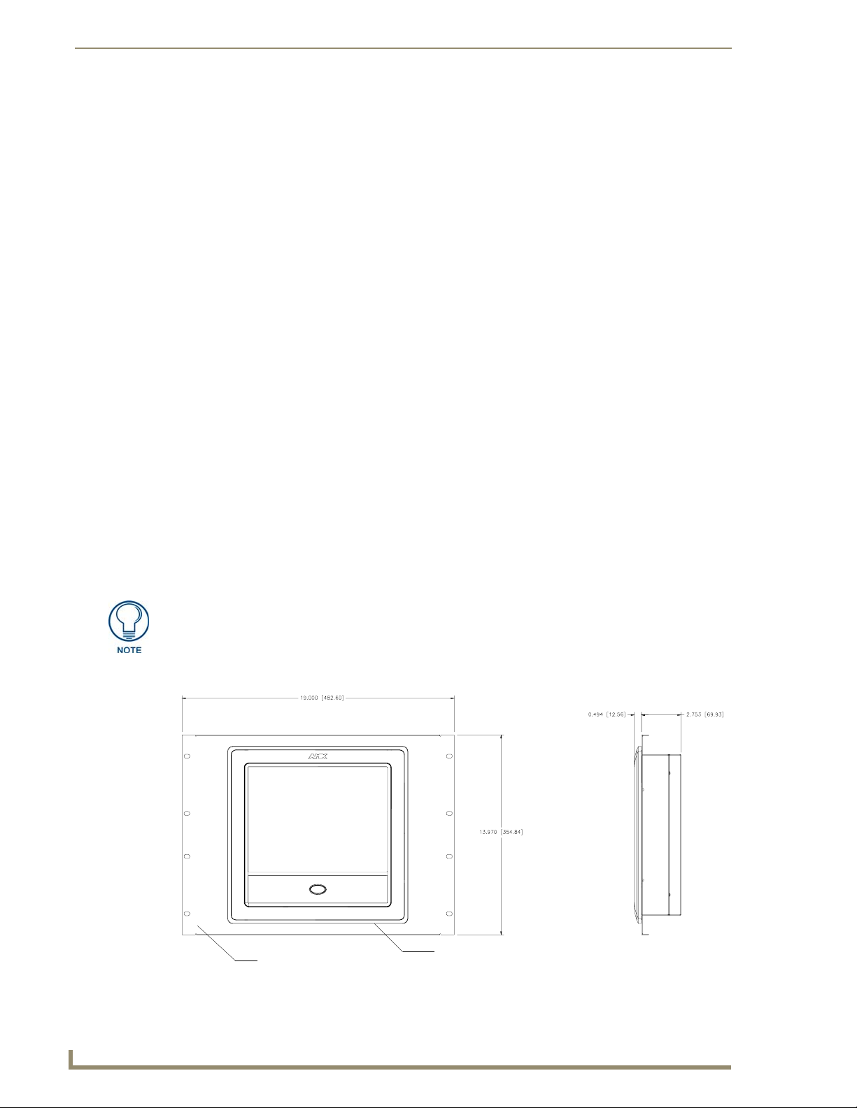
Installation Procedures: NXD-1200V Panels
10. Place the magnetic faceplate (A in FIG. 41) back onto the main NXD unit (B in FIG. 41).
Make sure to align the Microphone, Light, and PIR Motion sensor locations to their respective
openings on the front bezel/faceplate.
11. Reconnect the terminal RJ-45, Ethernet, USB, and any optional audio/video wiring to their
respective locations on either the NXA-AVB/ETHERNET Breakout Box, Ethernet port, or NetLinx
Master.
12. Reconnect the terminal power connector on the 12 VDC-compliant power supply and apply power.
Installing an NXD into an (optional) Rack Mount Kit (NXA-RK12)
1.
Remove the magnetic faceplate/bezel from the main NXD unit by gripping the faceplate and pulling
with gentle outward force.
2. Thread the incoming RJ-45, Ethernet, USB, and any optional audio/video wiring through the
opening in the equipment rack (from their terminal locations). Refer to the Wiring Guidelines for
the 1200V Panels section on page 45 for pinout descriptions. Leave enough slack to accommodate
any re-positioning of the panel.
3. Connect all data and power wiring connectors to their corresponding locations along the side of the
(un-powered) NXD touch panel.
Verify the terminal end of the power cable is not connected to a power supply before plugging
in the 2-pin power connector.
The USB connectors can be from a either a USB extension cable, or a wireless USB RF
transmitter.
4. Test the incoming wiring by connecting the panel connections to their terminal locations and
applying power. Verify the panel is receiving power and functioning properly to prevent repetition
of the installation.
5. Disconnect the terminal end of the power cable from the connected power supply.
Don’t disconnect the connectors from the touch panel. The unit must be installed with
the necessary connectors before being inserted into the equipment rack.
6. Insert the main 12-inch Modero unit into an NXA-RK12 (FIG. 42).
Rack mount
frame (NXA-RK12)
FIG. 42 NXD-1200V 12 inch Wall Mount panel installed into an NXA-RK12 Rack Mount Kit
Faceplate
44
1200V Modero Video Touch Panels
Page 55

Installation Procedures: NXD-1200V Panels
7. Secure the panel to the NXA-RK frame by first inserting and then tightening the four #4-40 screws
(provided). Line up the four mounting holes and use a grounded Phillips-head screwdriver to tighten
the screws in a clockwise direction.
8. Insert the NXA-RK (with connected NXD unit) into the equipment rack, making sure to align the
screw holes along the sides on the NXA-RK with the holes in the equipment rack.
9. Use a grounded Phillips-head screwdriver to secure the NXA-RK (with connected NXD unit) to the
equipment rack using #10-32 screws (not included).
10. Place the magnet faceplate back onto the main NXD unit by gripping the faceplate and placing it on
the housing with gentle force. Make sure to align the Microphone, Light, and PIR Motion sensor
locations to their respective openings on the front bezel/faceplate.
11. Reconnect the terminal RJ-45, Ethernet, and any optional audio/video wiring to their respective
locations on either the NXA-AVB/ETHERNET Breakout Box, Ethernet port, or NetLinx Master.
12. Reconnect the terminal power connector on the 12 VDC-compliant power supply and apply power.
Wiring Guidelines for the 1200V Panels
These panels require the use of a 12 VDC-compliant power supply to provide power to the panel via the
2-pin 3.5 mm mini-Phoenix PWR connector. Use the previously referenced power requirements
information to determine the power draw.
The incoming PWR and GND wires from the power supply must be connected to the corresponding
locations within the PWR connector.
These units should only have one source of incoming power. Using more than one
source of power to the touch panel can result in damage to the internal components
and a possible burn out.
Apply power to the panels only after installation is complete.
Preparing captive wires
You will need a wire stripper and flat-blade screwdriver to prepare and connect the captive wires.
Never pre-tin wires for compression-type connections.
1. Strip 0.25 inch (6.35 mm) of insulation off all wires.
2. Insert each wire into the appropriate opening on the connector (according to the wiring diagrams
and connector types described in this section).
3. Tighten the screws to secure the wire in the connector. Do not tighten the screws excessively; doing
so may strip the threads and damage the connector.
1200V Modero Video Touch Panels
45
Page 56
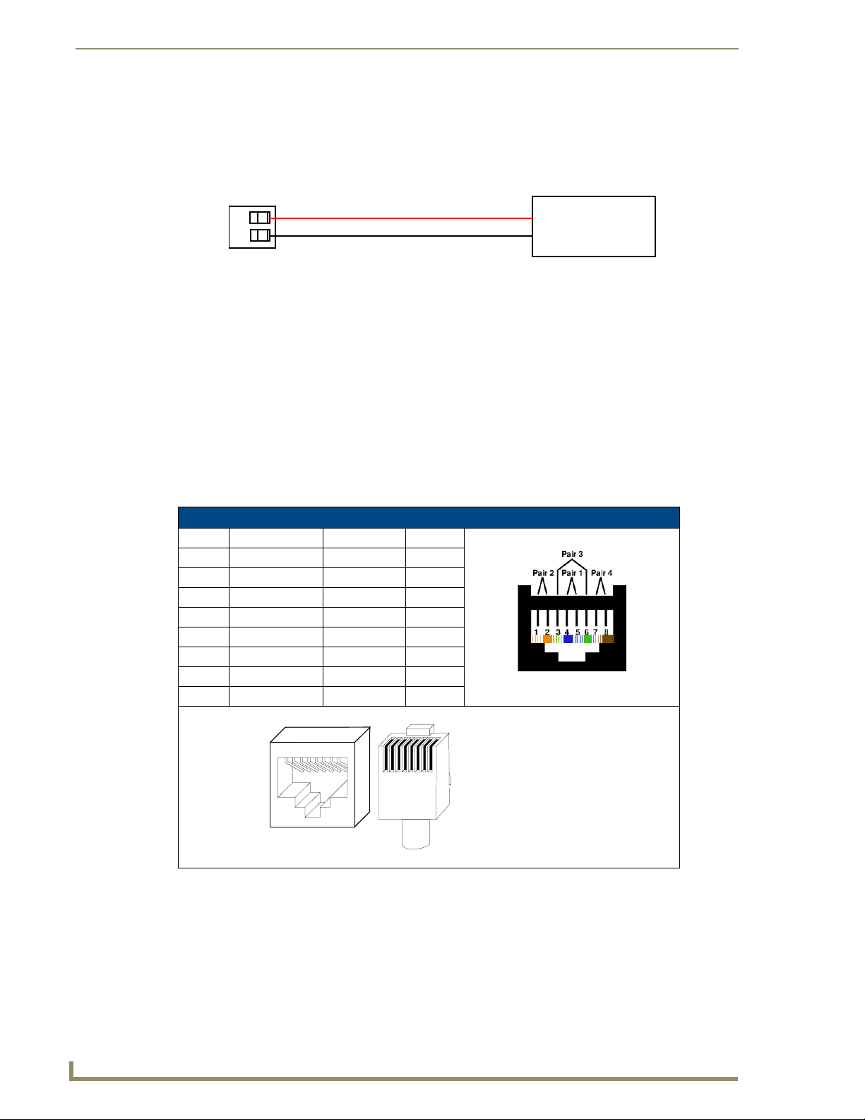
Installation Procedures: NXD-1200V Panels
Wiring a power connection
To use the 2-pin 3.5 mm mini-Phoenix connector with a 12 VDC-compliant power supply, the incoming
PWR and GND wires from the external source must be connected to their corresponding locations on the
connector (FIG. 43).
PWR +
GND -
To the Touch Panel
FIG. 43 NetLinx power connector wiring diagram
Power Supply
1. Insert the PWR and GND wires on the terminal end of the 2-pin 3.5 mm mini-Phoenix cable.
Match the wiring locations of the +/- on both the power supply and the terminal connector.
2. Tighten the clamp to secure the two wires. Do not tighten the screws excessively; doing so may strip
the threads and damage the connector.
3. Verify the connection of the 2-pin 3.5 mm mini-Phoenix to the power supply.
Audio/Video Port: Connections and Wiring
The following table shows the signal and pinout/pairing information used on the RJ-45 Audio and Video
connections.
Audio/Video RJ-45 Pinout Information
Pin Wire Color Function Polarity
1 Orange/White Right Audio In +
2 Orange Right Audio In -
3 Green/White Video In -
4 Blue Mic Out -
5 White/Blue Mic Out +
6 Green Video In +
7 White/Brown Left Audio In +
8 Brown Left Audio In -
TIA 568B
46
1 2 3 4 5 6 7 8
1 2 3 4 5 6 7 8
(female) (male)
RJ-45 connector - pin configurations
Refer to the Installing CAT5 Suppression Ferrites section on page 14 for detailed information on how to
install the necessary number of CAT5 Suppression Ferrites on the Black A/V RJ-45 cable connected to
the panel.
1200V Modero Video Touch Panels
Page 57
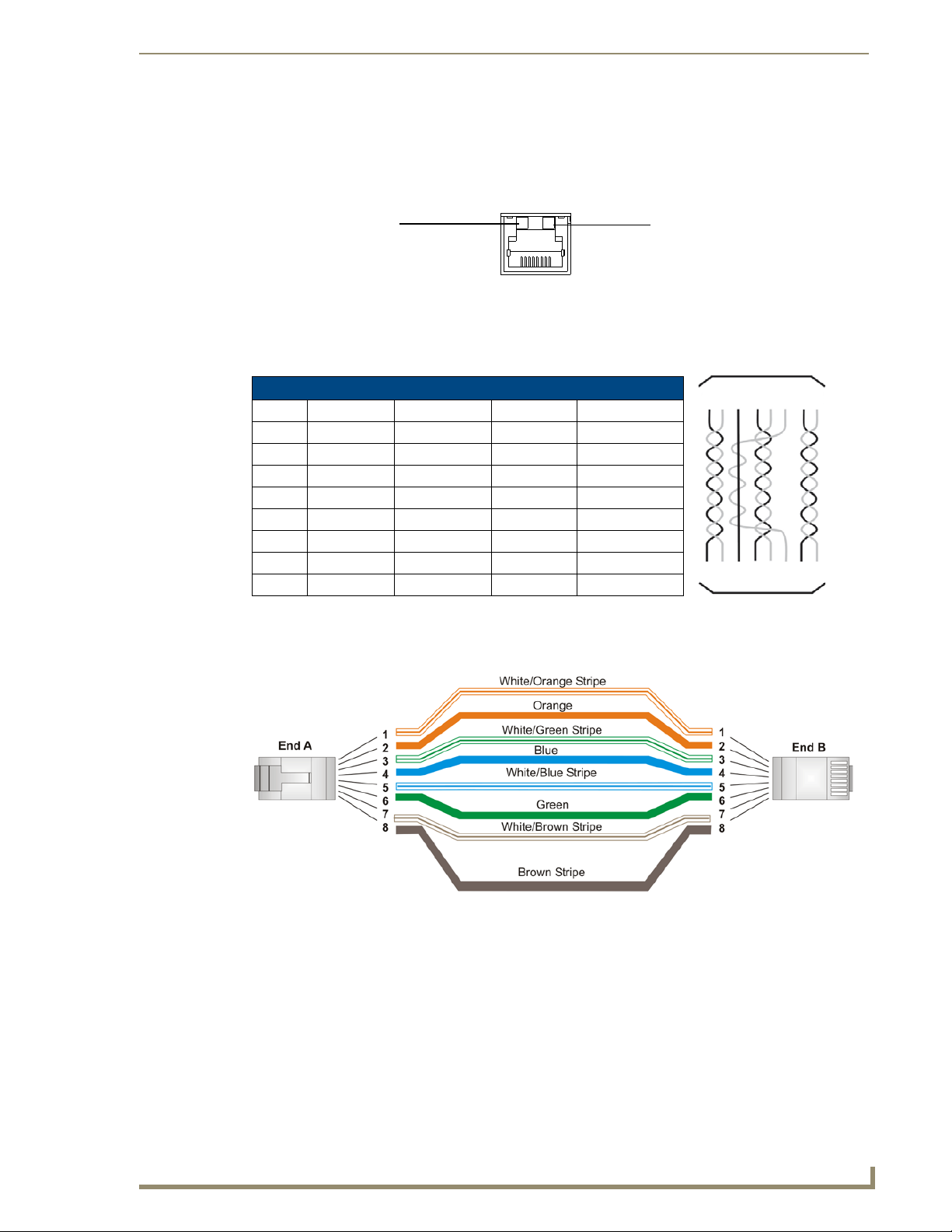
Installation Procedures: NXD-1200V Panels
Ethernet/RJ-45 Port: Connections and Wiring
FIG. 44 describes the blink activity for the Ethernet 10/100 Base-T RJ-45 connector and cable. The
Ethernet cable is connected to the side of the Wall Mount panels
A - Activity LED (yellow)
lights when receiving or
transmitting Ethernet
data packets
FIG. 44 Layout of Ethernet LEDs
A L
ETHERNET
10/100
L - Link LED (green) lights when
the Ethernet cables are connected
and terminated correctly.
The following table lists the pinouts, signals, and pairing associated with the Ethernet connector.
Ethernet RJ-45 Pinouts and Signals
Pin Signals Connections Pairing Color
1 TX + 1 --------- 1 1 --------- 2 Orange-White
2 TX - 2 --------- 2 Orange
3 RX + 3 --------- 3 3 --------- 6 Green-White
4 no connection 4 --------- 4 Blue
5 no connection 5 --------- 5 Blue-White
6 RX - 6 --------- 6 Green
7 no connection 7 --------- 7 Brown-White
8 no connection 8 --------- 8 Brown
12 3 456 78
12 3 456 78
FIG. 45 diagrams the RJ-45 pinouts and signals for the Ethernet RJ-45 connector and cable.
FIG. 45
1200V Modero Video Touch Panels
RJ-45 wiring diagram
47
Page 58

Installation Procedures: NXD-1200V Panels
48
1200V Modero Video Touch Panels
Page 59

Panel Calibration
This section outlines the steps for calibrating the touch panel. It is recommended that you calibrate the
panel before its initial use and after completing a firmware download.
Modero panels are factory setup with specific demo touch panel pages. The first splash screen that
appears indicates the panel is receiving power, beginning to load firmware, and preparing to display the
default touch panel pages. When the panel is ready, the AMX Splash Screen is replaced by the Initial
Panel Page (FIG. 46).
Panel Calibration
AMX Splash Screen
(appears during power-up)
FIG. 46 AMX splash screen and initial Panel Page
Initial Panel Page
(AMX Logo Page)
Calibrating the Modero Panel
1. Press and hold the grey Front Setup Access button (FIG. 47) for 6 seconds (passing-over the Setup
page) to access the Calibration setup page (FIG. 48). The panel should first be calibrated properly.
Front Setup
Access button (grey)
- 3 second press/hold:
Accesses the Setup page
- 6 second press/hold:
Accesses the Calibration
page
Single press puts
the panel to sleep
FIG. 47 Location of grey Front Setup Access button
1200V Modero Video Touch Panels
49
Page 60
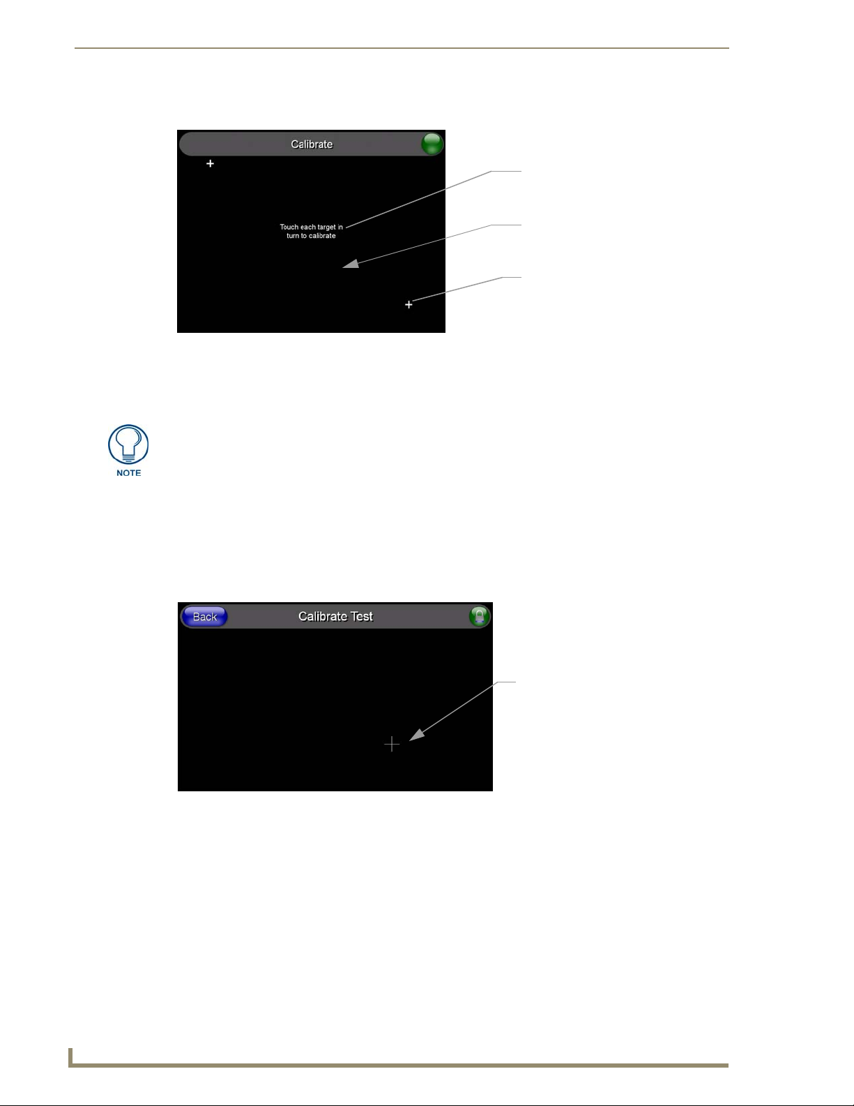
Panel Calibration
2. Press the crosshairs (on the Calibration page) to set the calibration points on the LCD (FIG. 48).
The request to touch the crosshairs
is the first on-screen message
Calibration successful is the second
on-screen message that appears
after the calibration process is
completed
On-screen crosshairs used for
calibration of the touch device
FIG. 48 Touch Panel Calibration Screens
3. After the "Calibration Successful.." message appears, press anywhere on the screen to continue and
return to the Setup page.
If the calibration was improperly set and you cannot return to the Calibration
page (through the panel’s firmware); you can access this firmware page via
G4 WebControl where you can navigate to the Protected Setup page and press the
Calibrate button through your VNC window.
This action causes the panel to go to the Calibration page seen above, where you
can physically recalibrate the actual touch panel again using the above procedures.
Testing your Calibration
Press and hold down the on-screen Calibration button for 6 seconds to enter the Calibration Test
1.
page (FIG. 49).
On-screen crosshairs is used to
verify a proper calibration of the
panel
FIG. 49 Calibration Test page
2. Press anywhere on this page to confirm the on-screen crosshairs match your touch points.
3. If the crosshairs do not appear directly below your LCD touch points, press the Back button and
recalibrate the panel using the above steps.
4. Exit this Calibration Test page by pressing the Back button to return to the Protected Setup page.
50
1200V Modero Video Touch Panels
Page 61
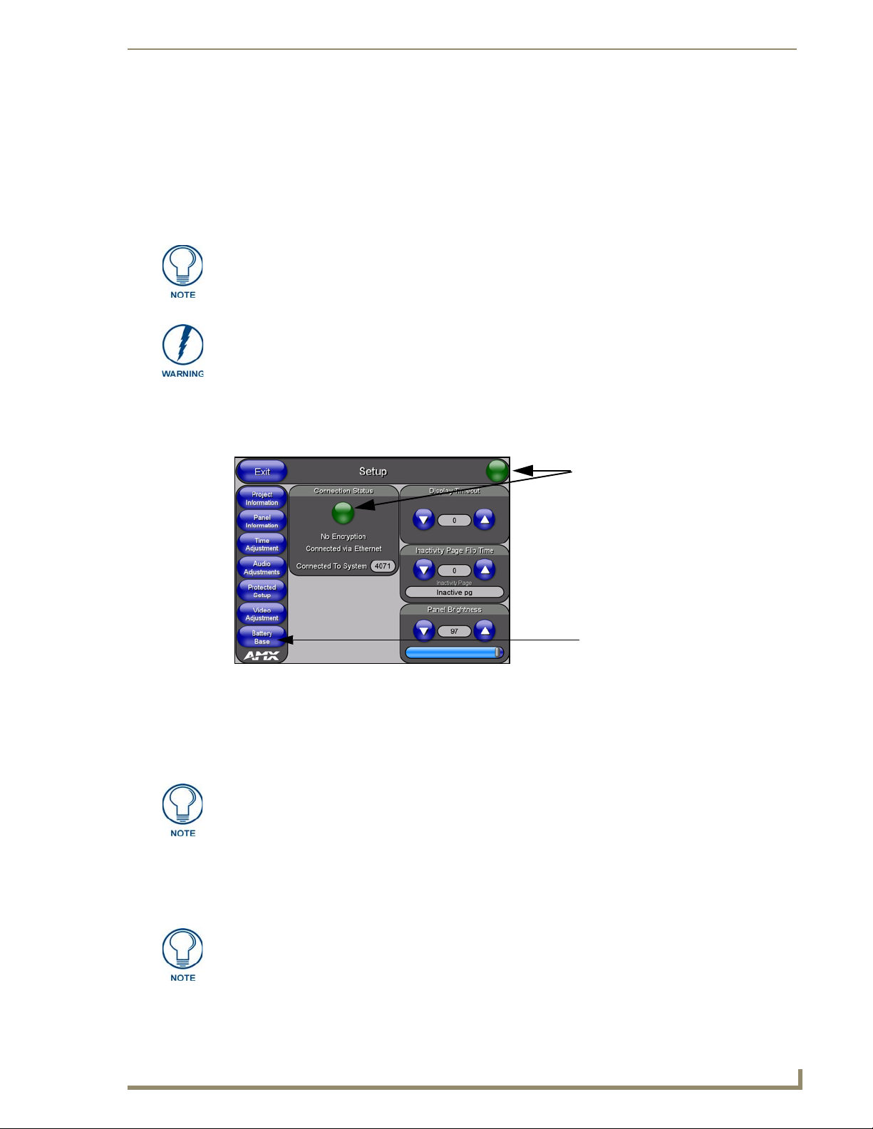
Configuring Communication
Communication between the Modero panel and the Master is done using either USB or ETHERNET
(DHCP or Static IP). Ethernet communication can be achieved through either a direct connection
(Ethernet) or through the use of the optional NXA-PCI80211G wireless interface card.
USB input devices must be plugged into the rear or side USB connectors before the
G4 panel is powered-up. The panel will not detect a USB connection of this type until
after the unit cycles power.
Before commencing, verify you are using the latest NetLinx Master and Modero panel
firmware. Verify you are using the latest versions of AMX’s NetLinx Studio and
TPDesign4 programs.
Modero Setup and System Connection
1. Press the grey Front Setup Access button for 3 seconds to open the Setup page (FIG. 50).
Configuring Communication
Connection Status
Red Connection Status icon -
indicates no connection to a Master
Green Connection Status icon -
indicates communication to a Master
Yel low Connection Status icon -
indicates an unreliable network
connection
Battery Base button doesn’t appear
until NXT is connected to a BASE/B
FIG. 50 Setup page
2. Press the Protected Setup button (located on the lower-left of the panel page) to open the Protected
Setup page and display an on-screen keypad.
3. Enter 1988 into the Keypad’s password field and press Done when finished.
Clearing Password #5, from the initial Password Setup page, removes the need for
you to enter the default password before accessing the Protected Setup page.
4. Press the red Device Number field to open the Device Number keypad (FIG. 51).
5. Enter a Device Number value for the panel into the Device Number Keypad.
The default is 10001 and the range is from 1 - 32000.
When using multiple panels within a NetLinx System, remember to assign unique
Device Number values to each panel so that all assigned panels appear in the
System listing for the target Master.
6. Press Done to close the keypad, assign the number, and return to the Protected Setup page.
1200V Modero Video Touch Panels
51
Page 62

Configuring Communication
FIG. 51 Protected Setup page
7. Press the on-screen Reboot button to restart the panel and incorporate any changes.
Before continuing, open NetLinx Studio 2.x. This program assists in developing a
System Number, Master IP/URL, and Master Port number. Refer to your NetLinx
Master’s instruction manuals for more information.
8. Obtain the System Number and Master IP Address from NetLinx Studio. This information must be
specific for the system used with the configured Modero panel.
9. Press the grey Front Setup Access button for 3 seconds to open the Setup page.
10. Press the Protected Setup button (located on the lower-left of the panel page) to open the Protected
Setup page.
11. Press the System Settings button (located on the Protected Setup page) to open the System Settings
page (FIG. 52) and begin configuring the communication settings on the panel to match those of the
target Master.
Modero
connection
information
MAC Address
from panel is
factory set to a
unique address
NetLinx Master’s
connection
information
52
FIG. 52 System Settings page
There are 2 possible Master Connection Types available: USB or Ethernet.
A USB connection type is a direct connection from the panel’s mini-USB port to a
corresponding USB port on the PC (acting as a Virtual Master).
An Ethernet connection type involves indirect communication from the panel to a
Master via an Ethernet connection to the network.
1200V Modero Video Touch Panels
Page 63

Configuring Communication
It is recommended that firmware KIT files only be transferred over a direct connection
and only when the panel is connected to a power supply. If battery power or wireless
connection fails during a firmware upgrade, the panel flash file system may become
corrupted.
The mini-USB connector MUST be plugged into an already active panel before the
PC can recognize the connection and assign an appropriate USB driver. This driver is
part of the latest TPDesign4 software application installation.
Configuring and Using USB with a Virtual Master
NetLinx Studio can be setup to run a Virtual Master where the PC acts as the Master by supplying its
own IP Address for communication to the panel. The PC is first equipped with the USB driver, the panel
is then configured for USB communication, and then Studio is configured to act as the Master.
For a personal computer to establish a connection to a Modero panel via USB, the target computer must
have the appropriate AMX USB driver installed. This installation is bundled into the latest TPDesign4
software setup process or can be downloaded independently from the main Application Files page on
www.amx.com.
Step 1: Setting up the Panel and PC for USB Communication
If you do not currently have the latest version of TPDesign4, navigate to www.amx.com > Te ch
1.
Center > Downloadable Files > Application Files > NetLinx Design Tools section of the website
and locate the AMX USB Driver executable (AMX USBLAN Setup exe).
2. Download this executable file to a known location on your computer.
3. Launch the file by double-clicking on it and follow the on-screen prompts to complete your
installation. Note that even if you have loaded the latest AMX Studio or TPD4 software, you will
still need to download and install this file if you are working with either the 1200V-Series or
VG-Series of panels.
4. Choose the default language, agree to the Licensing information, and choose the location for the file
installations (C:\Program Files\AMX\USBLAN).
5. From within the Choose Components dialog, select the features you wish to install. The Driver
option is selected by default and is the only item required.
6. Click the Install button to continue with the installation.
7. Once the application begins the installation of the corresponding USB driver files, it may encounter
cases where previous versions of these files already exist. This can occur if you have previously
installed released versions of NetLinx Studio and TPDesign4.
If you are prompted to replace the AXBLAN.INF file, select YES.
If you are prompted to replace the Checked driver file, select NO.
If you are prompted to replace the AXBLAN.SYS and AXFILT.SYS files, select Ye s.
8. Continue the setup process by following these OS-related processes:
For machines running Windows 2000 simply click the Next button when the installation is
complete. Creating a restore point is not an available option in 2000.
For Windows XP machines the setup program asks if you would like to create a restore point.
It is always a good idea to create restore points prior to installing new software.
Click the Next button when done.
9. At the end of the installation, press the Finish button.
1200V Modero Video Touch Panels
53
Page 64

Configuring Communication
Step 2: Confirming the Installation of the USB Driver on the PC
The first time each AMX touch panel is connected to the PC it is detected as a new hardware device and
the USBLAN driver becomes associated with it (panel specific). Each time thereafter the panel is
"recognized" as a unique USBLAN device and the association to the driver is done in the background.
When the panel is detected for the first time some user intervention is required during the association
between panel and driver.
1. After the installation of the USB driver has been completed, confirm the proper installation of the
large Type-A USB connector to the PC's USB port, and restart your machine.
If the panel is already powered, continue with steps 3.
The panel MUST be powered and configured for USB communication before
connecting the mini-USB connector to the panel’s Program Port.
2. Connect the terminal end of the 12 VDC-compliant power supply cable to the power connector on
the rear/side of the touch panel and then apply power.
3. After the panel powers-up, press and hold the grey Front Setup Access button (for 3 seconds) to
continue with the setup process and proceed to the Setup page.
4. Select Protected Setup > System Settings (located on the lower-left) to open the System Settings
page (FIG. 53).
No connection is established until
the Virtual Master becomes
active within Studio
Yel low Connection Status icon -
indicates an unreliable network
connection
Red Connection Status icon -
indicates no connection to a Master
Green Connection Status icon -
indicates communication to a Master
FIG. 53 System Settings page - using a USB Connection Type
5. Toggle the blue Ty pe field (from the Master Connection section) until the choice cycles to USB.
Refer to the System Settings Page section on page 118 for more information about the fields on this
page.
ALL fields are then greyed-out and read-only, but still display any previous network
information.
6. Press the Back button on the touch panel to return to the Protected Setup page.
7. Press the on-screen Reboot button to both save any changes and restart the panel. Remember that
the panel’s connection type must be set to USB prior to rebooting the panel and prior to inserting
the USB connector.
54
1200V Modero Video Touch Panels
Page 65
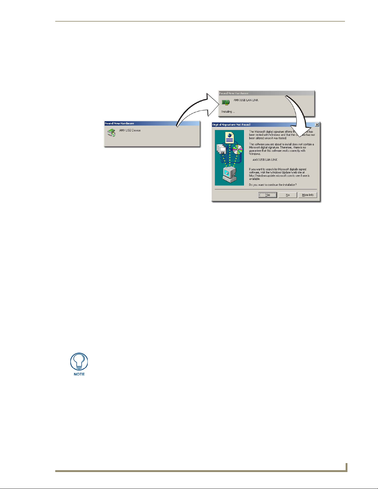
Configuring Communication
8. ONLY AFTER the unit displays the first panel page, THEN insert the mini-USB connector into
the Program Port on the panel. It may take a minute for the panel to detect the new connection and
send a signal to the PC (indicated by a green System Connection icon). If this is your first time
installing the USB driver, a USB driver installation popup window (FIG. 54) then appears on the
screen.
FIG. 54 USB driver installation popup window
This window notifies you that the panel has been detected by the PC as a USB-compliant
device and the PC is installing an appropriate USB driver to establish a proper communication
to the panel.
The driver does not contain a Microsoft
®
digital signature and Windows® then informs you of
such.
9. Click Ye s when told that a digital signature was not found. This action accepts the installation of the
new USB driver. The panel is now configured to communicate directly with the PC.
This process completes the association between driver and device.
Each time the same touch panel is connected to the computer the driver is automatically
loaded (using a unique name - example USB LAN LINK #1, #2).
Each time a different touch panel is connected to the computer, the previous procedures
will need to be repeated.
The previous version of the AMX USBLAN driver showed a USB connection icon in the
system tray when a panel was connected. The new version of the driver does not show an
icon in the System Tray.
A Virtual NetLinx Master (VNM) is used when the target panel is not connected to a
physical NetLinx Master. In this situation, the PC takes on the functions of a Master
via a Virtual NetLinx Master. This connection is made by either using the PC’s
Ethernet Address (via TCP/IP using a known PC’s IP Address as the Master) or
using a direct mini-USB connection to communicate directly to the panel.
10. Navigate back to the System Settings page.
1200V Modero Video Touch Panels
55
Page 66

Configuring Communication
Step 3: Confirm and View the current AMX USB device connections
1.
Navigate to Start > Settings > Control Panel > and double-click the System icon to launch the
System Properties dialog.
2. Select the Hardware tab and click on the Device Manager button to launch the Device Manager
dialog.
Within the Device Manager dialog, the AMX USBLAN device appears under Network
Adapters (FIG. 55) and has a unique name such as AMX USB LAN LINK #2. The number
changes depending on which recognized panel is currently connected.
USB connected touch
panel (showing the
recognized panel)
FIG. 55 Device Manager dialog showing USB device
To remove the USB driver association from a previously connected touch panel, you must navigate
back to the Device Manager, right-click on the panel’s USB driver (example AMX USB LAN LINK #2)
and select Uninstall from the context menu and then OK.
Once the system completes the removal of the device, the Device Manager window will
refresh, and the device will no longer appear.
The next time this device is connected to the computer it will appear as a new hardware device
and will need to be associated again with the driver (refer to Step 2: Confirming the
Installation of the USB Driver on the PC section on page 54.
Step 4: Using a USB to Configure a Virtual Master (using NetLinx Studio)
When configuring your panel to communicate via USB with a Virtual Master (on your
PC), ONLY the USB connection option must be selected within the Type field. Since
this is a direct connection, the PC’s IP Address is not needed.
Before beginning:
1. Verify the panel has been configured to communicate via USB within the System Settings page and
that the USB driver has been properly configured. Refer to the previous section for more
information.
2. Launch NetLinx Studio 2.x (default location is Start > Programs > AMX Control Disc > NetLinx
Studio 2 > NetLinx Studio 2).
3. Select Settings > Master Communication Settings, from the Main menu to open the Master
Communication Settings dialog (FIG. 56).
4. Click the Communications Settings button to open the Communications Settings dialog.
56
1200V Modero Video Touch Panels
Page 67

Configuring Communication
IP Address of computer
(not needed as this is a direct
USB connection)
FIG. 56 Assigning Communication Settings for a Virtual Master
5. Click on the NetLinx Master radio button (from the Platform Selection section) to indicate that you
are working as a NetLinx Master.
6. Click on the Virtual Master radio box (from the Transport Connection Option section) to indicate
you are wanting to configure the PC to communicate directly with a panel. Everything else such as
the Authentication is greyed-out because you are not going through the Master’s UI.
7. Click the Edit Settings button (on the Communications Settings dialog) to open the Virtual NetLinx
Master Settings dialog (FIG. 56).
8. From within this dialog enter the System number (default is 1).
9. Click OK three times to close the open dialogs, save your settings, and return to the main NetLinx
Studio application.
10. Click the OnLine Tree tab in the Workspace window to view the devices on the Virtual System.
The default System value is one.
11. Right-click on the Empty Device Tree/System entry and select Refresh System to re-populate the
list.
The panel will not appear as a device below the virtual system number (in the Online Tree tab)
until both the system number used in step 7 for the VNM is entered into the Master Connection
section of the System Settings page and the panel is restarted.
The Connection status turns green after a few seconds to indicate an active USB connection to
the PC (Virtual Master). No Lock icon is displayed because this USB connection is not
secured (requiring a username/password).
If a few minutes have gone by and the System Settings icon still does not turn green, repeat the
USB connection and Virtual Master setup procedures (outlined in this section). Refreshing the
System sends out a request to the panel to respond and completes the communication (turning
the System Connection icon green).
1200V Modero Video Touch Panels
57
Page 68

Configuring Communication
Step 5: Confirm and View the current AMX USB device connections
Use the CC-USB Type-A to Mini-B 5-wire programming cable (FG10-5965) to provide communication
between the mini-USB Program port on the touch panel and the PC. This method of communication is
used to transfer firmware KIT files and TPD4 touch panel files.
A mini-USB connection is only detected after it is installed onto an active panel.
Connection to a previously powered panel which then reboots, allows the PC to
detect the panel and assign an appropriate USB driver.
1. Verify this direct USB connection (Type-A on the panel to mini-USB on the panel) is configured
properly using the steps outlined in the previous two sections.
2. With the panel already configured for USB communication and the Virtual Master setup within
NetLinx Studio, its now time to verify the panel is ready to receive files.
3. Click the OnLine Tree tab in the Workspace window to view the devices on the Virtual System.
The default System value is one.
4. Right-click on the System entry (A in FIG. 57) and select Refresh System. This causes a refresh of
all project systems, establishes a new connection to the Virtual Master, and populates the System list
with devices on your particular system.
A
B
FIG. 57 Using USB for Virtual Master communication
58
1200V Modero Video Touch Panels
Page 69

Configuring Communication
Wireless Settings Page - Wireless Access Overview
IP Routing
The behavior of the wireless routing is largely dependent on the wired network interface. Although the
panel can be connected to two networks simultaneously it may only have one gateway. If the wired
network was successfully set up and a gateway was obtained; then the default route for all network traffic
will be via the wired network. In the event that the wired network was not configured, then the default
route for all network traffic will be via the wireless network. The wired network connection always takes
priority.
As an example:
Imagine a panel connected to two networks A & B. A is the wired network and B is the
wireless network. If the Master controller is on either of these networks then it will be
reached. However if the Master controller is on a different network, C, then determining
which network interface (wired or wireless) that will be used is dependent on the gateway.
Hot Swapping
Hot swapping is not an issue on these panels as the card is installed within the unit and cannot be
removed without first removing the housing.
In the case of DHCP, there must be a DHCP server accessible before the fields are populated.
If the SSID (Network Name) and WEP fields have not previously been configured, the
Wireless Settings page will not work until the panel is rebooted.
Ethernet Communication from the panel can be direct (using an Ethernet cable) or indirect (through the
NXA-PCI80211G AMX Wireless Card (FG2255-04) communicating to a Wireless Access Point (WAP)
such as the NXA-WAP200G). In determining the Ethernet method of communication, the panel will
always default first to the direct Ethernet communication. If no direct connection is detected, the panel
will first check to see if there is an installed wireless interface card and then communicate to the WAP
using the Wireless Settings assigned within the Wireless Settings page. The WAP communication
parameters must match those of the pre-installed wireless interface card installed within the panel.
Wireless Access Points are the cornerstone of any wireless network. A Wireless Access Point
acts as a bridge between a wired and wireless network. It aggregates the traffic from all the
wireless clients and forwards it down the network to the switch or router. One Wireless
Access Point may be all you need. However, you could need more Wireless Access Points
depending on either how large your installation is, how it is laid out, and how it is constructed.
Wireless Equivalent Privacy (WEP) Security is a method by which WLANs protect wireless
data streams. A data stream encrypted with WEP can still be intercepted or eavesdropped
upon, but the encryption makes the data unintelligible to the interloper. The strength of WEP
is measured by the length of the key used to encrypt the data. The longer the key, the harder it
is to crack.
802.11b implementations provided 40-bit and 104-bit WEP keys. This is known respectively
as 64-bit and 128-bit WEP encryption. 64-bit is generally not regarded as adequate security
protection. Both key lengths are supported by the Modero product line. Whichever level of
WEP you use, it's crucial to use identical settings (CASE SENSITIVE)--the key length, and
the key itself-- on all devices. Only devices with common WEP settings will be able to
communicate. Similarly, if one device has WEP enabled and another doesn't, they won't be
able to talk to each other.
1200V Modero Video Touch Panels
59
Page 70

Configuring Communication
Configuring a Wireless Connection
When working with a wireless card, the first step is to configure wireless communication parameters
within the Wireless Settings page. This page only configures the card to communicate to a target WAP
(such as the NXA-WAP200G), it is still necessary to tell the panel which Master it should be
communicating with. This "pointing to a Master" is done via the System Settings page where you
configure the IP Address, System Number and Username/Password information assigned to the target
Master.
Step 1: Configuring the Panel’s Wireless IP Settings
The first step to successfully setting up your wireless card is to configure the IP Settings section of the
Wireless Settings page. The section configures the communication parameters from the Modero panel to
the web.
Wireless communication using a DHCP Address
Press the Protected Setup button (located on the lower-left of the panel page) to open the Protected
1.
Setup page and display an on-screen keypad.
2. Enter 1988 into the Keypad’s password field and press Done when finished.
3. Press the Wireless Settings button (located on the lower-left) to open the Wireless Settings page.
Wireless communication is set within the IP Settings section of this page (FIG. 58).
4. Toggle the DHCP/Static field (from the IP Settings section) until the choice cycles to DHCP.
This action causes all fields in the IP Settings section (other than Host Name) to be greyed-out.
Although the calculations required to encrypt data with WEP can impact the performance of
your wireless network, it's generally seen only when running benchmarks, and not large
enough to be noticeable in the course of normal network usage.
DHCP will register the unique MAC Address (factory assigned) on the panel and
once the communication setup process is complete, assign IP Address, Subnet
Mask, and Gateway values from the DHCP Server.
5. Press the optional Host Name field to open a Keyboard and enter the Host Name information.
Modero
connection
IP info.
FIG. 58 Wireless Settings page (IP Settings section)
6. Press Done after you are finished assigning the alpha-numeric string of the host name.
7. Do not alter any of these remaining greyed-out fields in the IP Settings section. Once the panel is
rebooted, these values are obtained by the unit and displayed in the DNS fields after power-up.
60
1200V Modero Video Touch Panels
Page 71
Configuring Communication
This information can be found in either the Workspace - System name > Define
Device section of your code (that defines the properties for your panel), or in the
Device Addressing/Network Addresses section of the Tools > NetLinx Diagnostics
dialog.
8. Setup the security and communication parameters between the wireless card and the target WAP by
configuring the Wireless Settings section on this page. Refer to Step 2: Configuring the Card’s
Wireless Security Settings section on page 62 for detailed procedures to setup either a secure or
insecure connection.
Wireless communication using a Static IP Address
Press the Protected Setup button (located on the lower-left of the panel page) to open the Protected
1.
Setup page and display an on-screen keypad.
2. Enter 1988 into the Keypad’s password field and press Done when finished.
3. Press the Wireless Settings button (located on the lower-left) to open the Wireless Settings page.
Wireless communication is set within the IP Settings section of this page (FIG. 58).
Check with your System Administrator for a pre-reserved Static IP Address assigned
to the panel. This address must be obtained before Static assignment of the panel
continues.
4. Toggle the DHCP/Static field (from the IP Settings section) until the choice cycles to Static.
The IP Address, Subnet Mask, and Gateway fields then become user-editable (red).
5. Press the IP Address field to open a Keyboard and enter the Static IP Address (provided by your
System Administrator).
6. Press Done after you are finished entering the IP information.
7. Repeat the same process for the Subnet Mask and Gateway fields.
8. Press the optional Host Name field to open the Keyboard and enter the Host Name information.
9. Press Done after you are finished assigning the alpha-numeric string of the host name.
10. Press the Primary DNS field to open a Keyboard, enter the Primary DNS Address (provided by your
System Administrator) and press Done when compete. Repeat this process for the Secondary DNS
field.
11. Press the Domain field to open a Keyboard, enter the resolvable domain Address (this is provided
by your System Administrator and equates to a unique Internet name for the panel), and press Done
when complete.
12. Setup the security and communication parameters between the wireless card and the target WAP by
configuring the Wireless Settings section on this page. Refer to the following section for detailed
procedures to setup either a secure or insecure connection.
1200V Modero Video Touch Panels
61
Page 72

Configuring Communication
Step 2: Configuring the Card’s Wireless Security Settings
The second step to successfully setting up your wireless card is to configure the Wireless Settings section
of the Wireless Settings page. The section configures both the communication and security parameters
from the internal wireless card to the WAP. The procedures outlined within the following sections use
an NXA-WAP200G and the target WAP.
Once you have completed setting up the wireless card parameters, you must then
navigate to the System Settings page and configure the communication parameters
for the target Master. Until those parameters are configured, your Connection Status
icon will remain red (indicating that there is no current connection to a Master).
Configuring the Modero’s wireless card for unsecured access to a WAP200G
Power-down the Modero unit and follow the wireless card installation procedures outlined in Step 2:
1.
Install the 802.11g mini-PCI Wireless Card section on page 19.
2. Power-up the panel (this allows it to detect the card).
3. Press the Protected Setup button (located on the lower-left of the panel page) to open the Protected
Setup page and display an on-screen keypad.
4. Enter 1988 into the Keypad’s password field and press Done when finished.
5. Press the Wireless Settings button (located on the lower-left) to open the Wireless Settings page.
6. From within the Wireless Settings section of the Wireless Settings page, touch the Network Name
(SSID) field (FIG. 59).
Mini-PCI
settings
FIG. 59 Wireless Settings page (showing default values)
7. From the Service Set Identifier keyboard, enter the SSID name used by your target Wireless Access
Point (case sensitive).
The card should be given the SSID used by the target WAP. If this field is left blank, the unit
will attempt to connect to the first available WAP. By default, all WAP200Gs use AMX as
their assigned SSID value.
One of the most common problems associated with connection to a WAP arise because the
SSID was not entered properly. You must maintain the same case when entering the SSID
information. ABC is not the same as Abc.
8. Toggle the Authentication field to an Open System (default).
Open System Authentication allows any device to join the network if the panel’s SSID
matches the WAP’s SSID.
9. Toggle the Encryption field until it reads Clear Text (default).
62
1200V Modero Video Touch Panels
Page 73
Configuring Communication
The remaining Wireless Settings fields are then greyed-out and become read-only.
All NXA-WAP200Gs are factory-shipped as an unsecured WAP with no WEP
encryption. The WAP200G initial Status page will display the status of both the WEP
and WPA (both disabled).
10. Verify the fields in the IP Settings section have been properly configured. Refer to Step 1:
Configuring the Panel’s Wireless IP Settings section on page 60 for detailed information.
11. Press the Back button to navigate to the Protected Setup page and press the on-screen Reboot
button to both save any changes and restart the panel. Remember that you will need to navigate to
the System Settings page and configure the connection to a target Master.
12. After the panel restarts, return to the Wireless Settings page to verify the Link Quality and Signal
Strength:
The bargraphs have been replaced with descriptions: None, Poor, Fair, Good, Very Good,
and Excellent (FIG. 59).
The signal strength field should provide some descriptive text regarding the strength
of the connection to a Wireless Access Point. If there is no signal or no IP Address
displayed; configuration of your network could be required.
Refer to the NXA-WAP200G Instruction Manual for more detailed setup and configuration procedures.
Configuring the Modero’s wireless card for secured access to a WAP200G
After logging into the WAP200G, the default Status page appears within the web browser. These
read-only values are "pulled" from some of the other user-configurable Configuration Utility pages. By
default, wireless Modero panels are configured for unsecured communication to a Wireless Access
Point. To properly setup both the WAP200G and panel for secure communication, you must first prepare
the Modero panel and then use the information provided to fill out the fields within the WAP’s
browser-based Basic Wireless Configuration page.
Since the code key generator on Modero panels use the same key generation formula, all panels will
generate identical keys for the same Passphrase. The generators used on WAPs will not produce the same
key as the Modero generator even if you use the same Passphrase. This is why we recommend creating
the Current Key FIRST on the Modero and then entering that information into the appropriate
WA P 20 0G fi e l ds .
1. Power-down the Modero unit and follow the wireless card installation procedures outlined in Step 2:
Install the 802.11g mini-PCI Wireless Card section on page 19.
When configuring touch panels for wireless communication, verify that no Ethernet
connector is installed within the panel before the unit is power cycled.
2. Power-up the panel (this allows it to detect the card).
3. Press the Protected Setup button (located on the lower-left of the panel page) to open the Protected
Setup page and display an on-screen keypad.
4. Enter 1988 into the Keypad’s password field and press Done when finished.
5. Press the Wireless Settings button (located on the lower-left) to open the Wireless Settings page.
6. Locate the Wireless Settings section of the Wireless Settings page (FIG. 60).
1200V Modero Video Touch Panels
63
Page 74

Configuring Communication
FIG. 60 Wireless Settings page (Wireless Settings section)
You must first take the SSID name, Current Key string value, and panel MAC
Address information and then later enter it into the appropriate WAP dialog fields in
order to "sync-up" the secure connection. These values must be identically
reproduced on the target WAP.
7. Touch the Network Name (SSID) field and from the Service Set Identifier keyboard, enter the SSID
name you will be using on your target Wireless Access Point (case sensitive).
8. Leave the Authentication field reading Open System (default).
9. Toggle the Encryption field (FIG. 60) until it reads WEP64 or WEP128. The 64/128 selection
reflects the bit-level of encryption security. This WEP encryption level must match the encryption
level being used on the WAP.
SSID field
Mini-PCI wireless card communication
settings (for use with a target WAP)
Changes on this page take
effect after using the BACK
button to return to the
previous page
The card should be given the SSID used by the target WAP. If this field is left blank, the unit
will attempt to connect to the first available WAP. By default, all WAP200Gs use AMX as
their assigned SSID value.
One of the most common problems associated with connection to a WAP arise because the
SSID was not entered properly. You must maintain the same case when entering the SSID
information. ABC is not the same as Abc.
The alpha-numeric string is by default AMX but can later be changed to any 32-character
entry. This string must be duplicated within the Network Name (SSID) field on the WAP.
As an example, if you use TECHPUBS as your SSID, you must match this word and the
case within both the Network Name (SSID) field on the touch panel’s Network Name SSID
field and on the WAP’s Basic Wireless Configuration page.
Open System Authentication allows any device to join the network if the panel’s SSID
matches the WAP’s SSID. An Open System is recommended for communication between
Modero panels and an NXA-WAP200G.
Shared Key Authentication requires that the panel and the Wireless Access Point have the
same WEP Key to authenticate.
64
WEP will not work unless the same Default Key is set on both the panel and the
Wireless Access Point.
For example: if you have your Wireless Access Point set to default key 4 (which
was 01:02:03:04:05), you must set the panel’s key 4 to 01:02:03:04:05.
1200V Modero Video Touch Panels
Page 75

Configuring Communication
10. Toggle the Default Key field until the you’ve chosen a WEP Key value (from 1- 4) that matches
what you’ll be using on your target WAP200G.
These WEP Key identifier values must match for both devices.
11. With the proper WEP Key value displayed, press the Generate button to launch the WEP
Passphrase keyboard.
If you are wanting to have your target WAP (other than a 200G) generate the Current Key - Do
not press the Generate button and continue with Step 14.
This keyboard allows you to enter a Passphrase (such as AMXPanel) and then
AUTOMATICALLY generate a WEP key which is compatible only among Modero panels.
The code key generator on Modero panels use the same key generation formula.
Therefore, this same Passphrase generates identical keys when done on any
Modero because they all use the same Modero-specific generator. The Passphrase
generator is case sensitive.
12. Within this on-screen WEP Passphrase keyboard (FIG. 61), enter a character string or word (such as
AMXPanel) and press Done when you have finished.
FIG. 61 WEP Passphrase Keyboard
As an example, enter the word AMXPanel using a 128-bit hex digit encryption. After
pressing Done, the on-screen Current Key field displays a long string of characters (separated
by colons) which represents the encryption key equivalent to the word AMXPanel.
This series of hex digits (26 hex digits for a 128-bit encryption key) should be entered as
the Current Key into both the WAP and onto other communicating Modero panels by
using the WEP Key dialog (FIG. 62).
FIG. 62 WEP Key # Keyboard
1200V Modero Video Touch Panels
65
Page 76

Configuring Communication
13. Write down this Current Key string value for later entry into your WAP’s WEP Key field (typically
entered without colons) and into the communicating panel’s Current Key field (FIG. 60).
14. If you are entering a Current Key generated either by your target WAP or another Modero
panel, within the WEP Keys section, touch the Key # button to launch the WEP Key # keyboard
(FIG. 62), enter the characters and press Done when finished.
If your target Wireless Access Point does not support passphrase key generation and
has previously been setup with a manually entered WEP KEY, you must manually
enter that same WEP key on your panel.
15. Verify the fields within the IP Settings section have been properly configured. Refer to Step 1:
Configuring the Panel’s Wireless IP Settings section on page 60 for detailed information.
16. Press the Back button to navigate to the Protected Setup page and press the on-screen Reboot
button to both save any changes and restart the panel. Remember that you will need to navigate to
the System Settings page and configure the connection to a target Master.
17. After the panel restarts, return to the Wireless Settings page to verify the Link Quality and Signal
Strength:
This Key value corresponds to the Default WEP Key number used on the Wireless Access
Point and selected in the Default Key field described in the previous step.
The bargraphs have been replaced with descriptions: None, Poor, Fair, Good, Very Good,
and Excellent.
The signal strength field provides some descriptive text regarding the strength of the
connection to a Wireless Access Point. If there is no signal or no IP Address
displayed; configuration of your network could be required.
Refer to the NXA-WAP200G Instruction Manual for more detailed setup and configuration procedures.
Configuring multiple wireless Moderos to communicate to a target WAP200G
For each communicating touch panel, complete all of the steps outlined within the previous
1.
Configuring the Modero’s wireless card for secured access to a WAP200G section on page 63.
Those procedures walk you through assigning an SSID, selecting a WEP encryption level, and
obtaining a Current Key string value for a specific WEP Key on a target panel.
2. Navigate back to the Wireless/Wireless Settings page on each panel.
3. Verify that all communicating Modero panels are using the same SSID, encryption level, Default
Key #, and an identical Current Key value.
As an example, all panels should be set to Default Key #1 and be using aa:bb:cc..as the
Current Key string value. This same Key value and Current Key string should be used on the
target WAP.
4. Repeat steps 1 - 3 on each panel. Using the same passphrase, generates the same key for all
communicating Modero panels.
66
1200V Modero Video Touch Panels
Page 77
Configuring Communication
Configuring a Wired Ethernet Connection
It is necessary to tell the panel which Master it should be communicating with. This "pointing to a
Master" is done via the System Settings page where you configure the IP Address, System Number and
Username/Password information assigned to the target Master. If you have previously established a
wireless connection to the Internet you must still navigate to the System Settings page and configure the
communication parameters for the target Master. Until those parameters are configured, your Connection
Status icon will remain red (indicating there is no current connection to a Master).
If you have previously configured an internal wireless card for communication to the Internet,
you do not need to configure the panel’s IP Settings fields and can skip the following Step 1.
Step 1: Configuring the Panel’s Wired IP Settings
There are only two available methods of communicating to a target Master over the Internet: Wireless
(via an internal card) or Wired (direct Ethernet connection). If you are not using an internal wireless
card, you can only configure the connection parameters through the System Settings page. This type of
communication can be established either via either a Dynamic IP Address (DHCP) or via a
pre-reserved Static IP Address (typically provided by your System Administrator).
IP Settings section - Configuring a DHCP Address over Ethernet
1.
Select Protected Setup > System Settings (located on the lower-left) to open the System Settings
page.
2. Locate the IP Settings section of this page.
Even though the Host, Gateway, Primary DNS, Secondary DNS, and Domain fields
appear on the two separate System Settings and Wireless Settings pages; the
information populating these fields is identical.
If the information within one of these fields is altered, the change is reflected on both
pages within the altered field.
Example: Domain is altered on Wireless Settings page, the value is then also
changed within the Domain field of the System Settings page.
3. Toggle the DHCP/Static field (from the IP Settings section) until the choice cycles to DHCP.
DHCP will register the unique MAC Address (factory assigned) on the panel and
once the communication setup process is complete, reserve an IP Address, Subnet
Mask, and Gateway values from the DHCP Server.
4. Press the optional Host Name field to open a Keyboard and enter the Host Name information.
5. Press Done after you are finished assigning the alpha-numeric string of the host name.
6. Do not alter any of the remaining greyed-out fields in the IP Settings section. Once the panel is
rebooted, these values are obtained by the unit and displayed in the DNS fields after power-up.
This information can be found in either the: Workspace- System name > Define
Device section of your code (that defines the properties for your panel), or in the
Device Addressing/Network Addresses in the Tools > NetLinx Diagnostics dialog.
7. Press the Back button to return to the Protected Setup page.
8. Press the on-screen Reboot button to both save any changes and restart the panel.
1200V Modero Video Touch Panels
67
Page 78

Configuring Communication
IP Settings section - Configuring a Static IP Address over Ethernet
1.
Select Protected Setup > System Settings (located on the lower-left) to open the System Settings
page.
2. Locate the IP Settings section of this page.
Check with your System Administrator for a pre-reserved Static IP Address assigned
to the panel. This address must be obtained before Static assignment of the panel
continues.
3. Toggle the DHCP/Static field (from the IP Settings section) until the choice cycles to Static.
4. Press the IP Address field to open a Keyboard and enter the Static IP Address (provided by your
System Administrator).
5. Press Done after you are finished entering the IP information.
6. Repeat the same process for the Subnet Mask and Gateway fields.
7. Press the optional Host Name field to open the Keyboard and enter the Host Name information.
8. Press Done after you are finished assigning the alpha-numeric string of the host name.
9. Press the Primary DNS field to open a Keyboard, enter the Primary DNS Address (provided by your
System Administrator) and press Done when compete. Repeat this process for the Secondary DNS
field.
10. Press the Domain field to open a Keyboard, enter the resolvable domain Address (this is provided by
your System Administrator and equates to a unique Internet name for the panel), and press Done
when complete.
11. Navigate to the Master Connection section of this page to begin configuring the communication
parameters for the target Master.
Step 2: Choosing a Master Connection Mode Setting
There are three Ethernet MODE settings used in the Master Connection section of the System Settings
page. URL is the most common method.
Master Connection MODE options:
• URL (Uniform Resource Locator) is the address that defines the route to a file on the Web or
any other Internet facility.
In this system, the panel acts as a "Client" and the Master acts as a Server (in that Clients attach
to it).
• LISTEN sets the Modero panel to "listen" for broadcasts from the Master (using the panel IP from
its URL list). In this system, the panel acts as a "Server" (in that Clients attach to it) and the Master
acts as a "Client".
• AUTO is used to instruct the Modero to search for a Master that uses the same System Number
(assigned within the Master Connection section) and resides on the same Subnet as itself. In this
case, the Master has its UDP feature enabled.
This UDP (User Datagram Protocol) is a protocol within the TCP/IP protocol suite that is used in
place of TCP when a reliable delivery is not required.
This UDP enabling is done through a Telnet session on the Master. Refer to the particular NetLinx
Master manual for more detailed information.
68
1200V Modero Video Touch Panels
Page 79

Configuring Communication
Step 3: Configuring the Ethernet Connection Type
When using Ethernet as your communication method, the NetLinx Master must first
be setup with either a Static IP or DHCP Address obtained from either NetLinx Studio
or your System Administrator.
Before beginning:
1. Verify the panel has been configured to communicate either through an Ethernet cable (connected
from either the panel to a valid Ethernet Hub) or to a wirelessly to the Wireless Access Point
(WAP).
Before commencing, verify you are using the latest NetLinx Master firmware.
2. Verify that the NetLinx Master is receiving power and is communicating via an Ethernet connection
with the PC running NetLinx Studio.
3. Connect the terminal end of the 12 VDC-compliant power supply cable to the power connector on
the rear/side of the touch panel.
4. Verify the green Ethernet LED (from the rear Ethernet port on the Master) is illuminated (indicating
a proper connection).
5. Verify the yellow LED (from the rear Ethernet port on the Master) is blinking (indicating
communication).
6. After the panel powers-up, press and hold the grey Front Setup Access button (for 3 seconds) to
proceed to the Setup page.
7. Select Protected Setup > System Settings (located on the lower-left) to open the System Settings
page (FIG. 63).
Obtained
from
NetLinx
Master
FIG. 63 System Settings page
1200V Modero Video Touch Panels
69
Page 80
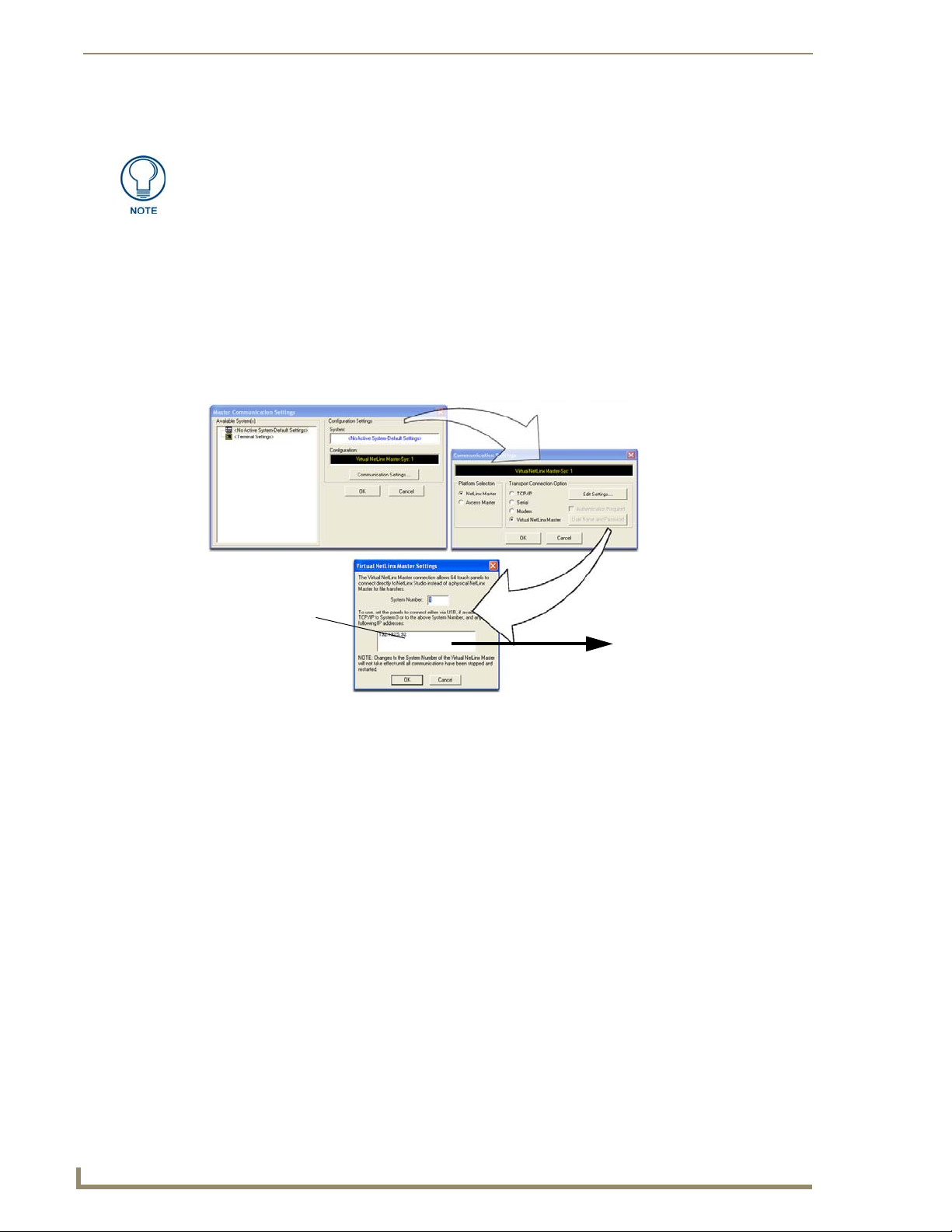
Configuring Communication
Master Connection - Virtual Master communication over Ethernet
When configuring your panel to communicate with a Virtual Master (on your PC) via
Ethernet, the Master IP/URL field must be configured to match the IP Address of the
PC and make sure to use the Virtual System value assigned to the Virtual Master
within NetLinx Studio.
Before beginning:
1. Verify the panel has been configured to communicate either through an Ethernet cable (connected
from either the panel to a valid Ethernet Hub) or wireless to the Wireless Access Point.
2. Launch NetLinx Studio 2.x (default location is Start > Programs > AMX Control Disc > NetLinx
Studio 2 > NetLinx Studio 2).
3. Select Settings > Master Communication Settings, from the Main menu to open the Master
Communication Settings dialog (FIG. 64).
Enter this IP
into the
Master IP/URL
field on the
System Settings
page
FIG. 64 Assigning Communication Settings and TCP/IP Settings for a Virtual Master
IP Addresses of computer
(also obtained by using the
Start > Run > cmd command)
4. Click the Communications Settings button to open the Communications Settings dialog.
5. Click on the NetLinx Master radio button (from the Platform Selection section) to indicate that you
are working as a NetLinx Master.
6. Click on the Virtual Master radio box (from the Transport Connection Option section) to indicate
you are wanting to configure the PC to communicate with a panel. Everything else such as the
Authentication is greyed-out because you are not going through the Master’s UI.
7. Click the Edit Settings button (on the Communications Settings dialog) to open the Virtual NetLinx
Master Settings dialog (FIG. 64).
8. From within this dialog enter the System number (default is 1) and note the IP Address of the target
PC being used as the Virtual Master. This IP Address can also be obtained by following these
procedures:
On your PC, click Start > Run to open the Run dialog.
Enter cmd into the Open field and click OK to open the command DOS prompt.
From the C:\> command line, enter ipconfig to display the IP Address of the PC. This
information is entered into the Master IP/URL field on the panel.
9. Click OK three times to close the open dialogs, save your settings, and return to the main NetLinx
Studio application.
70
1200V Modero Video Touch Panels
Page 81

Configuring Communication
10. Click the OnLine Tree tab in the Workspace window to view the devices on the Virtual System.
The default System value is one.
11. Right-click on the Empty Device Tree/System entry and select Refresh System to re-populate the
list.
12. Power-up your panel and press and hold the grey Front Setup Access button (for 3 seconds) to
continue with the setup process and proceed to the Setup page.
13. Select Protected Setup > System Settings (located on the lower-left) to open the System Settings
page (FIG. 65).
The System Number is
assigned to the Master
within the AMX
software application
(these must match)
Enter the IP Address
information of the PC
used as a Virtual
Master
When using a Virtual Master,
there is no need to enter a
username and/or password
FIG. 65 Sample System Settings page (for Virtual Master communication)
14. Press the blue Ty pe field (from the Master Connection section) until the choice cycles to the word
Ethernet. ICSNet communication cannot be used on either 1200V-Series or VG-Series panels.
15. Press the Mode field until the choice cycles to the word URL.
By selecting URL, the System Number field becomes read-only (grey) because the panel pulls
this value directly from the communicating target Master (virtual or not). A Virtual Master
system value can be set within the active AMX software applications such as: NetLinx Studio,
TPD4, or IREdit.
16. Press the Master IP/URL field to open a Keyboard and enter the IP Address of the PC used as the
Virtual Master.
17. Click Done to accept the new value and return to the System Settings page.
18. Do not alter the Master Port Number value (this is the default value used by NetLinx).
19. Press the Back button to open the Protected Setup page.
20. Press the on-screen Reboot button to both save any changes and restart the panel.
1200V Modero Video Touch Panels
71
Page 82

Configuring Communication
Master Connection section - NetLinx Master Ethernet IP Address - URL Mode
In this mode, enter the System Number (zero for an unknown System Number) and the IP/URL of the
Master (Master Port Number is defaulted to 1319).
1. Press the blue Typ e field (from the Master Connection section) until the choice cycles to the word
Ethernet. Refer to the System Settings Page section on page 118 for more information about the
fields on this page.
2. Press the Mode field until the choice cycles to the word URL.
If the panel does not appear within the OnLine Tree tab of the Workspace window of
NetLinx Studio, check to make sure that the NetLinx Master System Number (from
within the Device Addressing dialog) is correctly assigned.
3. Press the Master IP/URL field to open a Keyboard and enter the Master IP Address (obtained from
the Diagnostics - Networking Address dialog of the NetLinx Studio application).
4. Click Done to accept the new value and return to the System Settings page.
5. Do not alter the Master Port Number value (this is the default value used by NetLinx).
6. Enter a username and password (into their respective fields) if the target Master has been previously
secured.
7. Press the Back button to open the Protected Setup page.
8. Press the on-screen Reboot button to both save any changes and restart the panel.
By selecting URL, the System Number field becomes read-only (grey) because the panel pulls
this value directly from the communicating target Master (virtual or not). A Virtual Master
system value can be set within the active AMX software applications such as: NetLinx Studio,
TPD4, or IREdit.
Master Connection section - NetLinx Master Ethernet IP Address - Listen Mode
In this mode, you must add the Modero panel IP Address into the URL List of the Master (using NetLinx
Studio). This mode sets the Modero panel to "listen" for broadcasts from the Master (using the panel IP
from its URL list).
1. Obtain either a Static IP for the Modero panel (from your System Administrator) or a DHCP
Address from the IP Settings of the System Settings page.
The DHCP/Static field (in the IP Settings section of the System Settings page) must be set to
DHCP to get Dynamic IP information for the panel.
Press the on-screen Reboot (from the Protected Setup page) to both save any changes and
restart the panel.
After power-up, press the grey Front Setup Access button for 3 seconds to access the Setup
page.
Navigate to the Setup > Protected Setup > System Settings page and note the newly
obtained Dynamic IP Address information from the IP Settings section. This information is
then entered into the URL List for the connected NetLinx Master.
2. Toggle the blue Ty pe field until Ethernet is selected (from the Master Connection section of the
System Settings page).
3. Press the Mode field (to set the connection Mode) until the choice cycles to the word Listen.
4. Enter a username and password (into their respective fields) if the target Master has been previously
secured.
5. Select the OnLine Tree tab from the Workspace window.
72
1200V Modero Video Touch Panels
Page 83
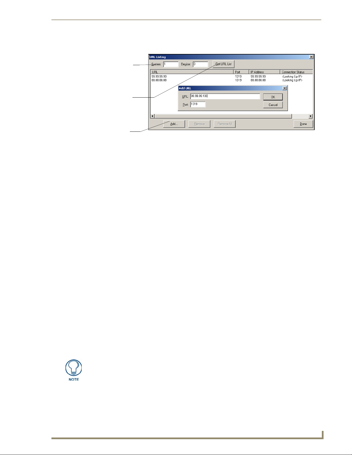
Configuring Communication
6. Select Diagnostics > URL Listing from the Main menu (FIG. 66).
System Address
reflects the value
set in the Device
Addressing tab
Used to obtain an
existing URL
List from Master
Used to set the
URL List
on Master
FIG. 66 URL List dialog
7. Enter the System and Device number for the specific Master associated with your panel (as seen in
the Online Tree tab).
8. Click Add and enter the IP Address of the Modero touch panel into the Add URL dialog box.
9. Click OK to enter your IP Address and add it to the list.
10. Click Done once you are finished adding your panel information to the list.
11. Press the on-screen Reboot button to save any changes and restart the panel.
Master Connection section - NetLinx Master Ethernet IP Address - Auto Mode
In this mode, enter the System Number of the NetLinx Master. This mode instructs the Modero to search
for a Master that uses the same System Number (assigned within the Master Connection section) and
resides on the same Subnet as itself.
1. Toggle the blue Ty pe field until Ethernet is selected (from the Master Connection section of the
System Settings page).
2. Press the Mode field until the choice cycles to the word Auto.
3. Press the System Number field to launch a Keypad and enter the value for the system number of the
NetLinx Master. This value can be obtained from the NetLinx Studio program > OnLine Tree of the
Workspace window.
4. Do not alter the IP Settings section, of the System Settings page, as these fields are not applicable to
this connection mode.
5. Enter a username and password (into their respective fields) if the target Master has been previously
secured.
6. Press the on-screen Reboot button to both save any changes and restart the panel.
7. Press the grey Front Setup Access button for 3 seconds to open the Setup page and confirm there is
an active connection.
The NetLinx Master and the Modero panel must both be on the same Subnet.
1200V Modero Video Touch Panels
73
Page 84

Configuring Communication
Using G4 Web Control to Interact with a G4 Panel
The G4 Web Control feature allows you to use a PC to interact with a G4 enabled panel via the web. This
feature works in tandem with the new browser-capable NetLinx Security firmware update
(build 300 or higher). G4 Web Control is only available with the latest Modero panel firmware.
Refer to the G4 Web Control Page section on page 108 for more detailed field information.
Verify your NetLinx Master (ME260/64 or NI-Series) has been installed with the latest
firmware KIT file from www.amx.com. Refer to your NetLinx Master Instruction
Manual for more detailed information on the use of the new web-based NetLinx
Security.
1. Press the grey Front Setup Access button for 3 seconds to open the Setup page.
2. Press the Protected Setup button (located on the lower-left of the panel page) to open the Protected
Setup page and display an on-screen keypad.
3. Enter 1988 into the Keypad’s password field (1988 is the default password).
Clearing Password #5, from the initial Password Setup page, removes the need for
you to enter the default password before accessing the Protected Setup page.
4. Press Done when finished.
5. Press the G4 Web Control button to open the G4 Web Control page (FIG. 67).
FIG. 67 G4 Web Control page
6. Press the Enable/Enabled button until it toggles to Enabled (light blue color).
7. The Network Interface Select field is read-only and displays the method of communication to the
web. Verify you have selected the proper interface connection as this field does not auto-detect
the connection type being used (see below).
Wired is used when a direct Ethernet connection is being used for communication to the web.
This is the default setting if either no wireless interface card is detected or if both an Ethernet
and wireless card connection is detected by the panel.
Wireless is used when a wireless card is detected within the internal card slot. This method
provides an indirect communication to the web via a pre-configured Wireless Access Point.
8. Press the Web Control Name field to open the Web Name keyboard.
74
1200V Modero Video Touch Panels
Page 85
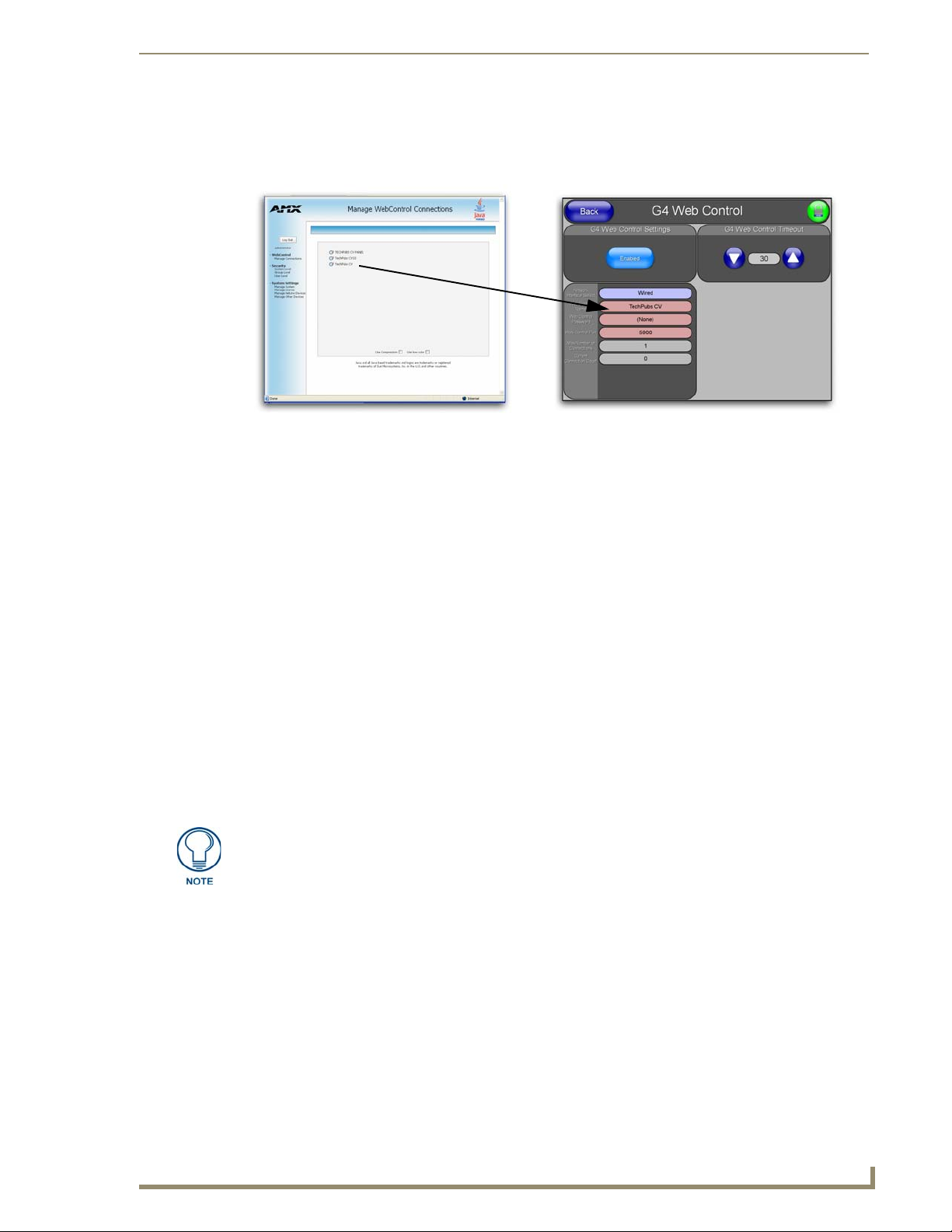
Configuring Communication
9. From the Web Name keyboard, enter a unique alpha-numeric string to identify this panel. This
information is used by the NetLinx Security Web Server to display on-screen links to the panel. The
on-screen links use the IP Address of the panel and not the name for communication (FIG. 68).
FIG. 68 Sample relationship between G4 Web Control and Mange WebControl Connections window
10. Press Done after you are finished assigning the alpha-numeric string for the Web Control name.
11. Press the Web Control Password field to open the Web Password keyboard.
12. From the Web Password keyboard, enter a unique alpha-numeric string to be assigned as the G4
Authentication session password associated with VNC web access of this panel.
13. Press Done after you are finished assigning the alpha-numeric string for the Web Control password.
14. Press the We b C ontrol Po r t field to open the Web Port Number keypad.
15. Within the keypad, enter a unique numeric value to be assigned to the port the VNC Web Server is
running on. The default value is 5900.
16. Press Done when you are finished entering the value. The remaining fields within the G4 Web
Control Settings section of this page are read-only and cannot be altered.
17. Press the Up/Down arrows on either sides of the G4 Web Control Timeo ut field to increase or
decrease the amount of time the panel can remain idle (no cursor movements) before the session is
closed and the user is disconnected.
18. Press the Back button to open the Protected Setup page.
19. Press the on-screen Reboot button to save any changes and restart the panel.
Verify your NetLinx Master’s IP Address and System Number have been properly
entered into the Master Connection section of the System Settings page.
1200V Modero Video Touch Panels
75
Page 86

Configuring Communication
Using your NetLinx Master to control the G4 panel
Refer to your particular NetLinx Master’s instruction manual for detailed information on how to
download the latest firmware from www.amx.com. This firmware build enables SSL certificate
identification and encryption, HTTPS communication, ICSP data encryption, and disables the ability to
alter the Master security properties via a TELNET session.
In order to fully utilize the SSL encryption, your web browser should incorporate the an encryption
feature. This encryption level is displayed as a Cipher strength.
Once the Master’s IP Address has been set through NetLinx Studio version 2.x or higher:
1. Launch your web browser.
2. Enter the IP Address of the target Master (ex: http://198.198.99.99) into the web browser’s Address
field.
3. Press the Enter key on your keyboard to begin the communication process between the target
Master and your computer.
4. Click OK to enter the information and proceed to the Master’s Manage WebControls window.
5. This Manage WebControl Connections page (FIG. 69) is accessed by clicking on the Manage
connections link (within the Web Control section within the Navigation frame). Once activated, this
page displays links to G4 panels running the latest G4 Web Control feature (previously setup and
activated on the panel).
Initially, the Master Security option is disabled (from within the System Security page) and
no username and password is required for access or configuration.
Both HTTP and HTTPS Ports are enabled by default (via the Manage System > Server
page).
If the Master has been previously configured for secured communication, click OK to accept
the AMX SSL certificate (if SSL is enabled) and then enter a valid username and password
into the fields within the Login dialog.
76
Compatible
devices field
(showing G4
G4 panels
FIG. 69 Manage WebControl Connections page (populated with compatible panels)
WebControl links)
Compression
Options
6. Click on the G4 panel name link associated with the target panel. A secondary web browser window
appears on the screen (FIG. 70).
1200V Modero Video Touch Panels
Page 87
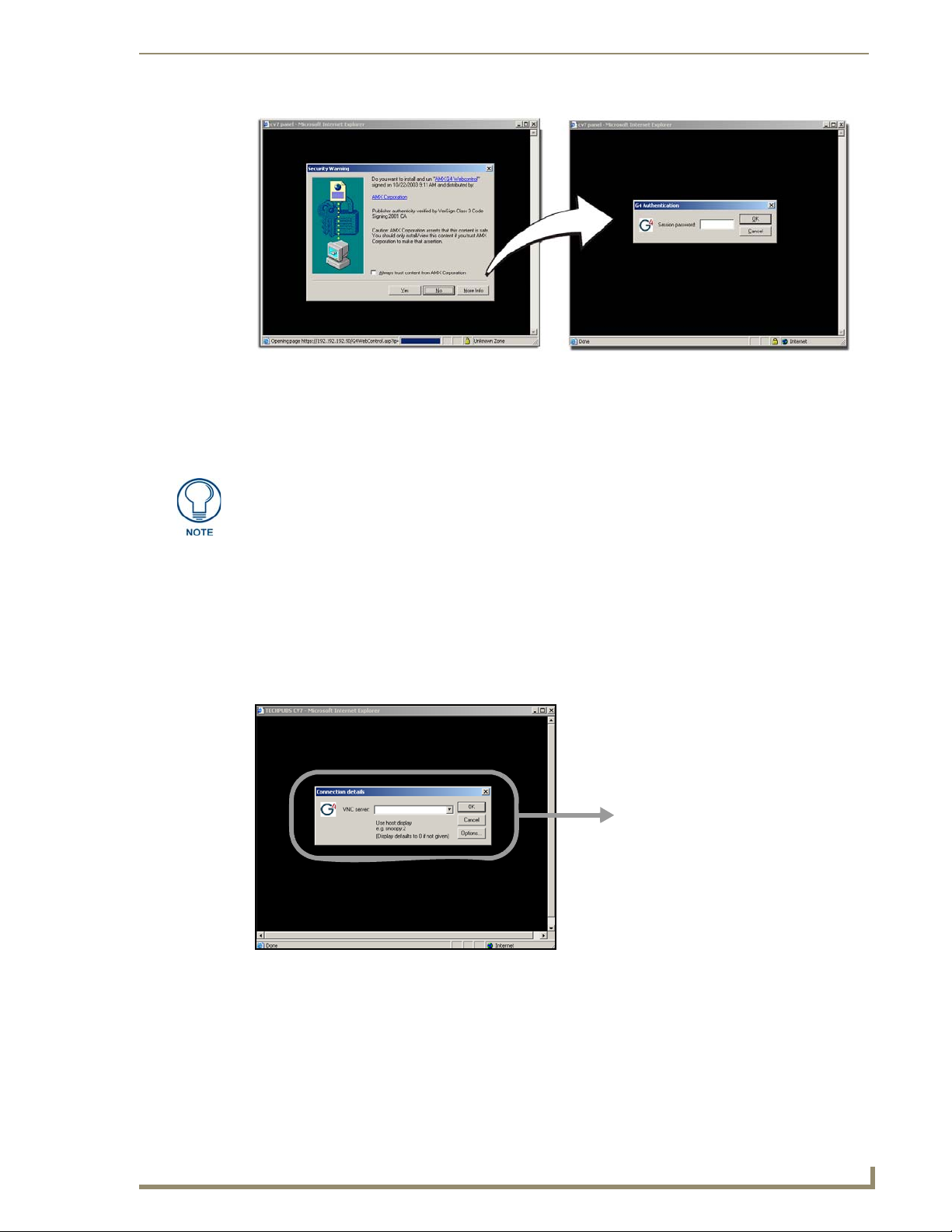
Configuring Communication
FIG. 70 Web Control VNC installation and Password entry screens
7. Click Ye s from the Security Alert popup window to agree to the installation of the G4 WebControl
application on your computer. This application contains the necessary Active X and VNC client
applications necessary to properly view and control the panel pages from your computer.
The G4 Web Control application is sent by the panel to the computer that is used for
communication. Once the application is installed, this popup will no longer appear.
This popup will only appear if you are connecting to the target panel using a different
computer.
8. In some cases, you might get a Connection Details dialog (FIG. 71) requesting a VNC Server IP
Address. This is the IP Address not the IP of the Master but of the target touch panel. Depending on
which method of communication you are using, it can be found in either the:
Wired Ethernet - System Settings > IP Settings section within the IP Address field.
Wireless - Wireless Settings > IP Settings section within the IP Address field.
If you do not get this field continue to step 9.
IP Address of touch panel
- obtained from IP Settings section of
the System Settings page
FIG. 71 Connection Details dialog
9. If a WebControl password was setup on the G4 WebControl page, a G4 Authentication Session
password dialog box appears on the screen within the secondary browser window.
10. Enter the Web Control session password into the Session Password field (FIG. 70). This password
was previously entered into the Web Control Password field within the G4 Web Control page on the
panel.
1200V Modero Video Touch Panels
77
Page 88

Configuring Communication
11. Click OK to send the password to the panel and begin the session. A confirmation message appears
stating "Please wait, Initial screen loading.".
The secondary window then becomes populated with the same G4 page being displayed on the target G4
panel. A small circle appears within the on-screen G4 panel page and corresponds to the location of the
mouse cursor. A left-mouse click on the computer-displayed panel page equates to an actual touch on the
target G4 panel page.
78
1200V Modero Video Touch Panels
Page 89

Upgrading Modero Firmware
Before beginning the Upgrade process:
Setup and configure your NetLinx Master. Refer to your particular NetLinx Master instruction
manual for detailed setup procedures.
Calibrate and prepare the communication pages on the Modero panel for use. Refer to the
Panel Calibration section on page 49.
Refer to the NetLinx Studio version 2.x or higher Help file for more information on uploading
files via Ethernet.
Configure your panel for either direct connect or wireless communication. Refer to the
Configuring Communication section on page 51 for more detailed information about Ethernet
or Wireless communication.
It is recommended that firmware Kit files only be transferred over a direct Ethernet
connection and only when the panel is connected to a power supply.
If battery power or wireless connection fails during a firmware upgrade, the panel
flash file system may become corrupted.
The process of updating firmware involves the use of a communicating NetLinx Master. The required
steps for updating firmware to a Modero panel are virtually identical to those necessary for updating Kit
files to a NetLinx Master (except the target device is a panel instead of a Master). Refer to either your
Master’s literature or Studio 2.x Help file for those procedures.
Upgrading Modero Firmware
A touch panel which is not using a valid username and password will not be able to
communicate with a secured Master. If you are updating the firmware on or through a
panel which is not using a username or password field, you must first remove the
Master Security feature to establish an unsecured connection.
Upgrading the Modero Firmware via the USB port
Before beginning with this section, verify your panel is powered and the Type-A USB connector is
securely inserted into the PC’s USB port. The panel must be powered-on before connecting the mini-
USB connector to the panel.
Establishing a USB connection between the PC and the panel, prior to installing the
USB Driver will cause a failure in the USB driver installation.
Step 1: Configure the panel for a USB Connection Type
After the installation of the USB driver has been completed, confirm the proper installation of the
1.
large Type-A USB connector to the PC's USB port, and restart your machine.
2. After the panel powers-up, press and hold the grey Front Setup Access button (for 3 seconds) to
continue with the setup process and proceed to the Setup page.
3. Select Protected Setup > System Settings (located on the lower-left) to open the System Settings
page.
4. Toggle the blue Ty pe field (from the Master Connection section) until the choice cycles to USB.
1200V Modero Video Touch Panels
79
Page 90

Upgrading Modero Firmware
ALL fields are then greyed-out and read-only, but still display any previous network
information.
5. Press the Back button on the touch panel to return to the Protected Setup page.
6. Press the on-screen Reboot button to both save any changes and restart the panel. Remember that
the panel’s connection type must be set to USB prior to rebooting the panel and prior to inserting
the USB connector.
7. ONLY AFTER the unit displays the first panel page, THEN insert the mini-USB connector into
the Program Port on the panel. It may take a minute for the panel to detect the new connection and
send a signal to the PC (indicated by a green System Connection icon).
8. Navigate back to the System Settings page.
Step 2: Prepare NetLinx Studio for communication via the USB port
Launch NetLinx Studio 2.x (default location is Start > Programs > AMX Control Disc > NetLinx
1.
Studio 2 > NetLinx Studio 2).
2. Select Settings > Master Communication Settings, from the Main menu to open the Master
Communication Settings dialog (FIG. 72).
If a few minutes have gone by and the System Connection icon still does not turn green,
complete the procedures in the following section to setup the Virtual Master and refresh the
System from the Online Tree. This action sends out a request to the panel to respond and
completes the communication (turning the System Connection icon green).
80
IP Address of computer
(not needed as this is a direct
USB connection)
FIG. 72 Assigning Communication Settings for a Virtual Master
3. Click the Communications Settings button to open the Communications Settings dialog.
4. Click on the NetLinx Master radio button (from the Platform Selection section) to indicate that you
are working as a NetLinx Master.
5. Click on the Virtual Master radio box (from the Transport Connection Option section) to indicate
you are wanting to configure the PC to communicate directly with a panel. Everything else such as
the Authentication is greyed-out because you are not going through the Master’s UI.
6. Click the Edit Settings button (on the Communications Settings dialog) to open the Virtual NetLinx
Master Settings dialog (FIG. 72).
1200V Modero Video Touch Panels
Page 91

Upgrading Modero Firmware
o
7. From within this dialog enter the System number (default is 1).
8. Click OK three times to close the open dialogs, save your settings, and return to the main NetLinx
Studio application.
9. Click the OnLine Tree tab in the Workspace window to view the devices on the Virtual System. The
default System value is one.
10. Right-click on the Empty Device Tree/System entry and select Refresh System to re-populate the
list.
The panel will not appear as a device below the virtual system number (in the Online Tree tab)
until both the system number used in step 7 for the VNM is entered into the Master Connection
section of the System Settings page and the panel is restarted.
Step 3: Confirm and Upgrade the firmware via the USB port
Use the CC-USB Type-A to Mini-B 5-wire programming cable (FG10-5965) to provide communication
between the mini-USB Program port on the touch panel and the PC. This method of communication is
used to transfer firmware Kit files and TPD4 touch panel files.
A mini-USB connection is only detected after it is installed onto an active panel.
Connection to a previously powered panel which then reboots, allows the PC to
detect the panel and assign an appropriate USB driver.
1. Verify this direct USB connection (Type-A on the panel to mini-USB on the panel) is configured
properly using the steps outlined in the previous two sections.
2. With the panel already configured for USB communication and the Virtual Master setup within
NetLinx Studio, its now time to verify the panel is ready to receive files.
3. After the Communication Verification dialog window verifies active communication between the
Virtual Master and the panel, click the OnLine Tree tab in the Workspace window (FIG. 73) to
view the devices on the Virtual System. The default System value is one.
4. Right-click on the System entry (FIG. 73) and select Refresh System to re-populate the list. Verify
the panel appears in the OnLine Tree tab of the Workspace window.
The default Modero panel value is 10001.
Showing a Master
firmware version and
device number
Showing the current Moder
panel firmware version and
device number
Shows NetLinx Studio
version number
FIG. 73 NetLinx Workspace window (showing panel connection via a Virtual NetLinx Master)
The panel firmware is shown on the right of the listed panel.
Download the latest firmware file from www.amx.com and then save the Kit file to
your computer.
1200V Modero Video Touch Panels
81
Page 92
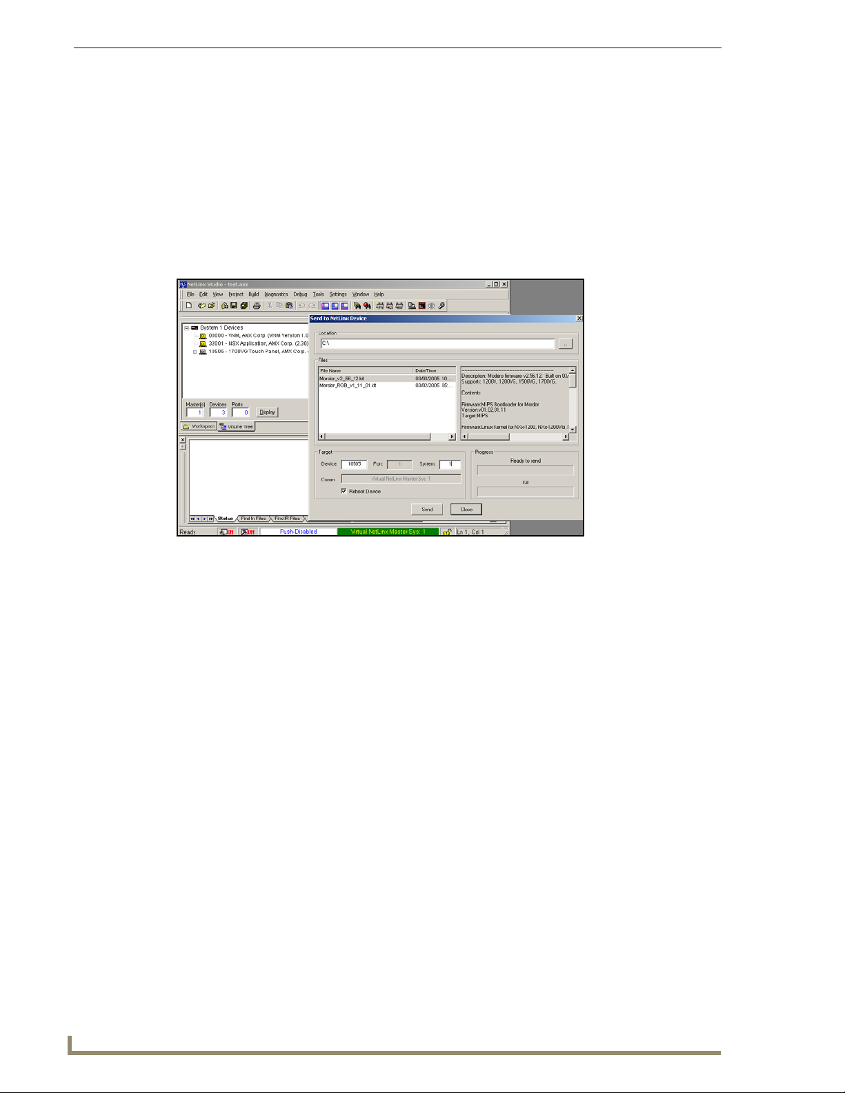
Upgrading Modero Firmware
5. If the panel firmware being used is not current, download the latest Kit file by first logging in to
www.amx.com and then navigate to Tech Center > Firmware Files and from within the Modero
section of the web page locate your Modero panel.
6. Click on the desired Kit file link and after you’ve accepted the Licensing Agreement, verify you
have downloaded the Modero Kit file to a known location.
7. From within Studio, select Tools > Firmware Transfers > Send to NetLinx Device from the Main
menu to open the Send to NetLinx Device dialog (B in FIG. 74). Verify the panel’s System and
Device number values match those values listed within the System folder in the OnLine Tree tab of
the Workspace window (A in FIG. 74).
A
B
FIG. 74 Using USB for a Virtual Master transfer
8. Select the panel’s Kit file from the Files section.
9. Enter the Device value associated with the panel and the System number associated with the Master
(listed in the OnLine Tree tab of the Workspace window). The Port field is greyed-out.
10. Click the Reboot Device checkbox. This causes the touch panel to reboot after the firmware update
process is complete. The reboot of the panel can take up 30 seconds after the firmware process has
finished.
11. Click Send to begin the transfer. The file transfer progress is indicated on the bottom-right of the
dialog (B in FIG. 74).
12. As the panel is rebooting, temporarily unplug the USB connector on the panel until the panel has
completely restarted.
13. Reconnect the USB connector to the panel.
14. Right-click the associated System number and select Refresh System. This causes a refresh of all
project systems, establishes a new connection to the Master, and populates the System list with
devices on your particular system.
15. Confirm the panel has been properly updated to the correct firmware version.
82
1200V Modero Video Touch Panels
Page 93

Upgrading Modero Firmware
Upgrading the Modero Firmware via an IP Address
Before beginning with this section, verify that your panel is powered and connected to the NetLinx
Master through an Ethernet connection (direct or wireless).
Step 1: Prepare the Master for communication via an IP
1.
Obtain the IP Address of the NetLinx Master from your System Administrator. If you do not have
an IP Address for the Master, refer to your particular Master’s instruction manual for more
information on obtaining this IP Address using NetLinx Studio 2.
From the Online Tree tab of the Workspace window, select the NetLinx Master.
Follow steps outlined in either the Obtaining or Assigning the Master’s IP Address sections
from your particular NetLinx Master instruction manual to use an address.
Note the IP Address and Gateway information.
2. Launch NetLinx Studio 2.x (default location is Start > Programs > AMX Control Disc > NetLinx
Studio 2 > NetLinx Studio 2).
3. Select Settings > Master Communication Settings from the Main menu to open the Master
Communication Settings dialog (FIG. 75).
FIG. 75 Assigning Communication Settings and TCP/IP Settings
4. Click the Communications Settings button to open the Communications Settings dialog.
5. Click on the NetLinx Master radio button (from the Platform Selection section) to indicate you are
working with a NetLinx Master (such as the NXC-ME260/64 or NI-Series of Integrated
Controllers).
6. Click on the TCP/IP radio button (from the Transport Connection Option section) to indicate you
are connecting to the Master through an IP Address.
7. Click the Edit Settings button (on the Communications Settings dialog) to open the TCP/IP
Settings dialog (FIG. 75). This dialog contains a series of previously entered IP Address/URLs and
their associated names, all of which are stored within Studio and are user-editable.
1200V Modero Video Touch Panels
83
Page 94

Upgrading Modero Firmware
8. Click the New button to open the New TCP/IP Settings dialog where you can enter both a
previously obtained DHCP or Static IP Address and an associated description for the connection
into their respective fields.
9. Place a checkmark within the Automatically Ping the Master Controller to ensure availability radio
box to make sure the Master is initially responding online before establishing full communication.
10. Click OK to close the current New TCP/IP Settings dialog and return to the previous TCP/IP
Settings dialog where you must locate your new entry within the List of Addresses section.
11. Click the Select button to make that the currently used IP Address communication parameter.
12. Click OK to return to the Communications Settings dialog and place a checkmark within the
Authentication Required radio box if your Master has been previously secured with a
username/password.
13. Click on the Authentication Required radio box (if the Master is secured) and then press the User
Name and Password button to open the Master Controller User Name and Password dialog.
14. Within this dialog, you must enter a previously configured username and password (with sufficient
rights) before being able to successfully connect to the Master.
15. Click OK to save your newly entered information and return to the previous Communication
Settings dialog where you must click OK again to begin the communication process to your Master.
If you are currently connected to the assigned Master, a popup asks whether you
would want to temporarily stop communication to the Master and apply the new
settings.
16. Click Ye s to interrupt the current communication from the Master and apply the new settings.
17. Click Reboot (from the Tools > Reboot the Master Controller dialog) and wait for the System
Master to reboot. The STATUS and OUTPUT LEDs should begin to alternately blink during the
incorporation. Wait until the STATUS LED is the only LED to blink.
18. Press Done once until the Master Reboot Status field reads *Reboot of System Complete*.
19. Click the OnLine Tree tab in the Workspace window to view the devices on the System.
The default System value is one (1).
20. Right-click the associated System number and select Refresh System. This establishes a new
connection to the specified System and populates the list with devices on that system. The
communication method is then highlighted in green on the bottom of the NetLinx Studio window.
Step 2: Prepare the panel for communication via an IP
1.
Press the blue Typ e field (from the Master Connection section) until the choice cycles to the word
Ethernet.
2. Press the blue Mode field until the choice cycles to the word URL.
By selecting URL, the System Number field becomes read-only (grey) because the panel pulls
this value directly from the communicating target Master (virtual or not). A Virtual Master
system value can be set within the active AMX software applications such as: NetLinx Studio,
TPD4, or IREdit.
3. Press the red Master IP/URL field to open a Keyboard and enter the NetLinx Master’s IP Address
(obtained from the Diagnostics - Networking Address dialog of the NetLinx Studio
application).
4. Click Done to accept the new value and return to the System Configuration page.
5. Do not alter the Master Port Number value (this is the default value used by NetLinx).
84
1200V Modero Video Touch Panels
Page 95

Upgrading Modero Firmware
6. Press the Back button to return to the Protected Setup page and press the on-screen Reboot button
to restart the panel and save any changes.
Step 3: Verify and Upgrade the panel firmware via an IP
Click the OnLine Tree tab in the Workspace window to view the devices on the System. The default
1.
System value is one.
2. Right-click the associated System number (from the Workspace window) and select Refresh
System to detect of all devices on the current system, establish a new connection to the Master, and
refresh the System list with devices on that system.
3. After the Communication Verification dialog window verifies active communication between the
PC and the Master, verify the panel appears in the OnLine Tree tab of the Workspace window
(FIG. 76). The default Modero panel value is 10001.
Showing a Master
firmware version and
device number
Showing the current Modero
panel firmware version and
device number
Shows NetLinx Studio
version number
FIG. 76 NetLinx Workspace window (showing connected Modero panel)
The panel firmware is shown on the right of the listed panel.
4. If the panel firmware being used is not current, download the latest Kit file by first logging in to
www.amx.com and then navigate to Tech Center > Firmware Files and from within the Modero
section of the web page locate your Modero panel.
5. Click on the desired Kit file link and after you’ve accepted the Licensing Agreement, verify you
have downloaded the Modero Kit file to a known location.
6. From within Studio, select Tools > Firmware Transfers > Send to NetLinx Device from the Main
menu to open the Send to NetLinx Device dialog (FIG. 77). Verify the panel’s System and Device
number values match those values listed within the System folder in the OnLine Tree tab of the
Workspace window.
7. Select the panel’s Kit file from the Files section (FIG. 77).
8. Enter the Device value associated with the panel and the System number associated with the Master
(listed in the OnLine Tree tab of the Workspace window). The Port field is greyed-out.
9. Click the Reboot Device checkbox. This causes the touch panel to reboot after the firmware update
process is complete. The reboot of the panel can take up 30 seconds after the firmware process has
finished.
10. Click Send to begin the transfer. The file transfer progress is indicated on the bottom-right of the
dialog (FIG. 77).
1200V Modero Video Touch Panels
85
Page 96
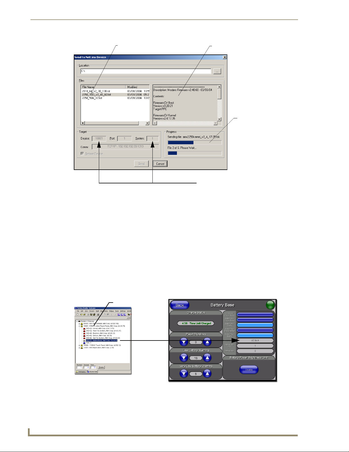
Upgrading Modero Firmware
Selected Firmware file
FIG. 77 Send to NetLinx Device dialog (showing Modero firmware update via IP)
Description field for selected Kit file
Firmware download
status
Device value and System number
must match the values
listed in the Workspace window
11. Click Close (after the panel reboots) to return to the main program.
12. Right-click the associated System number and select Refresh System. This causes a refresh of all
project systems, establishes a new connection to the Master, and populates the System list with
devices on your particular system.
13. Confirm the panel has been properly updated to the correct firmware version.
Upgrading Accessory Devices via the USB
The following accessory devices are firmware upgradeable:
NXA-BASE/B Battery Base (FG2255-10)
This device is not given a unique device number which would ordinarily appear within the Online Tree
tab of NetLinx Studio. It appears below the target panel which it is a part of as seen below in FIG. 78.
Target Panel Device #
NXA-BASE/B
(base version)
NetLinx Studio Online Tree tab Accessory’s corresponding firmware page
FIG. 78 Location of Firmware version information within NetLinx Studio
86
1200V Modero Video Touch Panels
Page 97

Upgrading Modero Firmware
The only way to upgrade the firmware of an accessory item is to send the accessory’s firmware through a
target panel. Its this panel’s device number which is entered within the Send to NetLinx Device transfer
dialog in Studio.
Step 1: Prepare the NXA-BASE/B for firmware transfer via USB
Before beginning with this section:
Unplug any connectors from the rear of the NXT panel (power, Ethernet, etc.).
Refer to the Installing the NXA-BASE/B to an NXT Modero Panel section on page 27 for
installation procedures to mount the NXT atop the battery base.
DO NOT PLACE BATTERIES IN THE BASE BEFORE CONNECTING IT TO THE
NXT PANEL. Insert batteries into the NXA-BASE/B ONLY AFTER the base has been
installed onto the bottom of the NXT panel.
Having batteries in the base before connection can damage the battery base.
Verify your NXA-BASE/B is securely attached to the bottom of the NXT panel.
Once the base is secured, side out the battery compartment and install the batteries into the
battery base. Once the batteries are installed, close the compartment.
Reconnect all rear connectors to the NXT panel.
1. Complete the instructions for configuring the NetLinx Master for IP communication found in the
Upgrading the Modero Firmware via the USB port section on page 79.
2. Press the grey Front Setup Access button for 3 seconds to open the Setup page.
3. Press the Battery Base button to open the Battery Base page (FIG. 79).
FIG. 79 Battery Base page
The battery base firmware is shown on the right of the Battery Base page.
Verify you have downloaded the latest firmware file from www.amx.com and then
save the Kit file to your computer.
1200V Modero Video Touch Panels
87
Page 98

Upgrading Modero Firmware
Step 2: Upgrade the NXA-BASE/B firmware via USB
1.
Complete the procedures outlined in the Step 1: Configure the panel for a USB Connection
Type section on page 79.
2. Prepare NetLinx Studio for communication to the panel via a Virtual Master by following the
procedures outlined in the Step 2: Prepare NetLinx Studio for communication via the USB
port section on page 80.
3. After the Communication Verification dialog window verifies active communication between the
Virtual Master and the panel, click the OnLine Tree tab in the Workspace window to view the
devices on the Virtual System. The default System value is one.
4. Right-click on the System entry and select Refresh System to re-populate the list. Verify the panel
appears in the OnLine Tree tab of the Workspace window.
The default Modero panel value is 10001.
5. Locate the latest Kit file by first logging in to www.amx.com and then navigate to Tech Center >
Firmware Files and from within the Modero section of the web page locate the Battery Base.
6. Click on the desired Kit file link and after you’ve accepted the Licensing Agreement, verify you
have downloaded the Modero Battery Base Kit file to a known location.
7. From within Studio, select Tools > Firmware Transfers > Send to NetLinx Device from the Main
menu to open the Send to NetLinx Device dialog. Verify the panel’s System and Device number
values match those values listed within the System folder in the OnLine Tree tab of the Workspace
window.
8. Select the battery base’s Kit file from the Files section.
9. Enter the Device number associated with the panel and the System number associated with the
Master (listed in the OnLine Tree tab of the Workspace window). The Port field is greyed-out.
The firmware for the battery base can not be downloaded directly. Download of the
Kit file to the BASE/1 is done through the panel.
10. Click the Reboot Device checkbox. This causes the touch panel to reboot after the firmware update
process is complete. The reboot of the panel can take up 30 seconds after the firmware process has
finished.
11. Click Send to begin the transfer. The file transfer progress is indicated on the bottom-right of the
dialog.
12. As the panel is rebooting, temporarily unplug the USB connector on the panel until the panel has
completely restarted.
13. Reconnect the USB connector to the panel.
14. Right-click the associated System number and select Refresh System. This causes a refresh of all
project systems, establishes a new connection to the Master, and populates the System list with
devices on your particular system.
15. Confirm the base has been properly updated to the correct firmware version by pressing the Battery
Base button to open the Battery Base page.
88
1200V Modero Video Touch Panels
Page 99

Upgrading Modero Firmware
Upgrading Accessory Devices via an IP Address
The following accessory devices are firmware upgradeable:
NXA-BASE/B Battery Base (FG2255-10)
This device is not given a unique device number which would ordinarily appear within the Online Tree
tab of NetLinx Studio. It appears below the target panel which it is a part of as seen in FIG. 78 on
page 86.
The only way to upgrade the firmware of an accessory item is to send the accessory’s firmware through a
target panel. Its this panel’s device number which is entered within the Send to NetLinx Device transfer
dialog in Studio.
Firmware can also be downloaded to accessory items via a direct USB connection
using the PC as a Virtual Master. In this case, you will still need to know the System
and Device Number information of the target panel. For a more detailed description of
how to setup this type of connection, refer to the Upgrading Accessory Devices via
the USB section on page 86.
Step 1: Prepare the NXA-BASE/B for firmware transfer via an IP
Before beginning with this section:
Unplug any connectors from the rear of the NXT panel (power, Ethernet, etc.).
Refer to the Installing the NXA-BASE/B to an NXT Modero Panel section on page 27 for
installation procedures to mount the NXT atop the battery base.
DO NOT PLACE BATTERIES IN THE BASE BEFORE CONNECTING IT TO THE
NXT PANEL. Insert batteries into the NXA-BASE/B ONLY AFTER the base has been
installed onto the bottom of the NXT panel.
Having batteries in the base before connection can damage the battery base.
Verify your NXA-BASE/B is securely attached to the bottom of the NXT panel.
Once the base is secured, side out the battery compartment and install the batteries into the
battery base. Once the batteries are installed, close the compartment.
Reconnect all rear connectors to the NXT panel.
1. Complete the instructions for configuring the NetLinx Master for IP communication found in the
Step 1: Prepare the Master for communication via an IP section on page 83.
2. Press the grey Front Setup Access button for 3 seconds to open the Setup page.
3. Press the Battery Base button to open the Battery Base page (FIG. 80).
FIG. 80 Battery Base page
1200V Modero Video Touch Panels
89
Page 100

Upgrading Modero Firmware
The battery base firmware is shown on the right of the Battery Base page.
Verify you have downloaded the latest firmware file from www.amx.com and then
save the Kit file to your computer.
Step 2: Upgrade the NXA-BASE/B firmware via an IP
Click on the OnLine Tree tab in the Workspace window to view the devices on the System.
1.
The default System value is one.
2. Right-click the associated System number (from the Workspace) and select Refresh System to
detect of all devices on the current system, establish a new connection to the Master, and refresh the
System list with devices on that system.
3. After the Communication Verification dialog window verifies active communication between the
PC and the Master, verify the target panel appears in the OnLine Tree tab of the Workspace
window. The default Modero panel value is 10001. The NXA-BASE/B will not appear on the system
listing.
4. Locate the latest Kit file by first logging in to www.amx.com and then navigate to Tech Center >
Firmware Files and from within the Modero section of the web page locate the Modero Battery
Base section of the website.
5. Click on the desired Kit file link and after you’ve accepted the Licensing Agreement, verify you
have downloaded the Modero Battery Base Kit file to a known location.
6. From within Studio, select Tools > Firmware Transfers > Send to NetLinx Device from the Main
menu to open the Send to NetLinx Device dialog (FIG. 81). Verify the panel’s System and Device
number values match those values listed within the System folder in the OnLine Tree tab of the
Workspace window.
Selected Battery Base Firmware file
FIG. 81 Send to NetLinx Device dialog (showing NXA-BASE/B firmware update via IP)
Description field for selected Kit file
Firmware download
status
Device value and System number
must match the values
listed in the Workspace window
7. Select the battery base’s Kit file (ending in VXX.kit) from the Files section (FIG. 81).
90
1200V Modero Video Touch Panels
 Loading...