

Page 1
Operation/Reference Guide
Modero® VG-Series
G4 Touch Panels
NXD/NXT-1200VG, NXD/NXT-1500VG,
and NXD/NXT-1700VG
Touch Panels
Last Revised: 10/1/2008
Page 2

AMX Limited Warranty and Disclaimer
All products returned to AMX require a Return Material Authorization (RMA) number. The RMA number is
obtained from the AMX RMA Department. The RMA number must be clearly marked on the outside of each
box. The RMA is valid for a 30-day period. After the 30-day period the RMA will be cancelled. Any shipments
received not consistent with the RMA, or after the RMA is cancelled, will be refused. AMX is not responsible
for products returned without a valid RMA number.
Warranty Repair Policy
• AMX will repair any defect due to material or workmanship issues during the applicable warranty period at no cost to the AMX
Authorized Partner., provided that the AMX Authorized Partner is responsible for in-bound freight and AMX is responsible for
out-bound ground freight expenses.
• The AMX Authorized Partner must contact AMX Technical Support to validate the failure before pursuing this service.
• AMX will complete the repair and ship the product within five (5) business days after receipt of the product by AMX. The AMX
Authorized Partner will be notified if repair cannot be completed within five (5) business days.
• Products repaired will carry a ninety (90) day warranty or the balance of the remaining warranty, whichever is greater.
• Products that are returned and exhibit signs of damage or unauthorized use will be processed under the Non-Warranty Repair
Policy.
• AMX will continue to provide Warranty Repair Services for products discontinued or replaced by a Product Discontinuance
Notice.
Non-Warranty Repair Policy
• Products that do not qualify to be repaired under the Warranty Repair Policy due to age of the product or Condition of the product may be repaired utilizing this service.
• The AMX Authorized Partner must contact AMX Technical Support to validate the failure before pursuing this service.
• Non-warranty repair is a billable service.
• Products repaired under this policy will carry a ninety (90) day warranty on material and labor.
• AMX will notify the AMX Authorized Partner with the cost of repair, if cost is greater than the Standard Repair Fee, within five (5)
days of receipt.
• The AMX Authorized Partner must provide a Purchase Order or credit card number within five (5) days of notification, or the
product will be returned to the AMX Authorized Partner.
• The AMX Authorized Partner will be responsible for in-bound and out-bound freight expenses.
• Products will be repaired within ten (10) business days after AMX Authorized Partner approval is obtained.
• Non-repairable products will be returned to the AMX Authorized Partner with an explanation.
• See AMX Non-Warranty Repair Price List for minimum and Standard Repair Fees and policies.
Page 3
FCC Information
This device complies with Part 15 of the FCC Rules. Operation is subject to the following two conditions: (1) this device
may not cause harmful interference, and (2) this device must accept any interference received; including interference
that may cause undesired operation.
Federal Communications Commission (FCC)
Statement
This equipment has been tested and found to comply with the limits for a Class B digital device, pursuant to Part 15 of
the FCC rules. These limits are designed to provide reasonable protection against harmful interference in a residential
installation. This equipment generates, uses and can radiate radio frequency energy, and, if not installed and used in
accordance with the instructions, may cause harmful interference to radio communications. However, there is no
guarantee that interference will not occur in a particular installation. If this equipment does cause harmful
interference to radio or television reception, which can be determined by turning the equipment off and on, the user is
encouraged to try to correct the interference by one or more of the following measures:
• Reorient or relocate the receiving antenna.
• Increase the separation between the equipment and receiver.
• Connect the equipment into an outlet on a circuit different from that to which the receiver is connected.
• Consult the dealer or an experienced radio/TV technician for help.
FCC RF Radiation Exposure Statement
This transmitter must not be co-located or operating in conjunction with any other antenna or transmitter. This
equipment complies with FCC RF radiation exposure limits set forth for an uncontrolled environment. This equipment
should be installed an operated with a minimum distance of 20 centimeters between the radiator and your body.
Page 4

Page 5

Table of Contents
Table of Contents
Introduction ........................................................................................................1
Multimedia Streaming Video Touch Panels (VG-Series) ............................................ 1
Product Specifications (NXD-1200VG and NXT-1200VG) ............................................... 2
Product Specifications (NXD-1500VG and NXT-1500VG) ............................................... 7
Product Specifications (NXD-1700VG and NXT-1700VG) ............................................. 12
VG-Series Modero Connectors ............................................................................... 17
Connecting and Using USB Input Devices............................................................... 17
Cleaning the Touch Overlay.................................................................................... 18
Touch Panel Accessories ................................................................................... 19
Overview ................................................................................................................ 19
NXA-AVB/RGB Breakout Box (FG2254-11)............................................................. 19
Product Specifications .................................................................................................. 20
RGB RJ-45 connection and wiring information.............................................................. 21
Using the HD-15 high-density connector ...................................................................... 22
Installing the NXA-AVB/RGB......................................................................................... 22
Wiring the NXA-AVB/RGB connectors and cables......................................................... 23
Wiring the NXA-AVB/RGB for Unbalanced Audio......................................................... 24
Wiring the NXA-AVB/RGB for Balanced Audio ............................................................. 25
Preparing your panel for Pass-Thru Control (using the NXA-AVB/RGB Breakout Box) . 26
Wiring for Pass-Thru Computer Control........................................................................ 27
NXA-MTC/RGB Combo Table Top Cable (CA2250-70) ........................................... 28
Product Specifications ................................................................................................ 28
Wiring and Connection Information .............................................................................. 29
Installing CAT5 Suppression Ferrites............................................................................. 30
NXA-RGB RGB/VGA Interface Card (FG2260) ........................................................ 31
Product Specifications .................................................................................................. 32
Supported Component/VGA Video Resolutions and Formats ..................................... 33
RGB RJ-45 connection and wiring information.............................................................. 33
NXA-CFTP Compact Flash (FG2116-22).................................................................. 34
NXA-PCI80211G Wireless Card (FG2255-04).......................................................... 35
Product Specifications ............................................................................................... 35
Installation and Upgrade of the Internal NXT Components.................................... 37
Step 1: Remove the existing NXT Outer Housing......................................................... 37
Step 2: Install the 802.11g mini-PCI Wireless Card ....................................................... 38
Step 3: Install the NXA-RGB Card Component (NXT).................................................... 39
Step 4: Install the Compact Flash Memory Card upgrade............................................. 40
Step 5: Close and Resecure the NXT Panel Enclosure................................................... 41
VG-Series Modero Touch Panels
i
Page 6

Table of Contents
Installation and Upgrade of the Internal NXD Components ................................... 42
Step 1: Remove the existing NXD Outer Housing......................................................... 42
Step 2: Install the new 802.11g mini-PCI Wireless card (NXD)...................................... 43
Step 3: Install the new RGB Card Component (NXD).................................................... 43
Step 4: Install the new Compact Flash Memory card (NXD).......................................... 43
Step 5: Close and Resecure the NXD Panel Enclosure .................................................. 43
NXT-BP Power Pack (FG2255-10) ........................................................................... 44
Product Specifications .................................................................................................. 44
NXA-BASE/B Battery Base Kit (FG2255K) .............................................................. 45
Product Specifications .................................................................................................. 45
Checking the NXT-BP battery charge............................................................................ 46
Installing the NXA-BASE/B to an NXT Modero Panel.................................................... 46
Installing an NXT-BP into the NXA-BASE/B................................................................... 47
Charging the NXT-BP batteries with the NXA-BASE/B ................................................. 48
NXT-CHG Battery Charger Kit (FG2255-50K) ......................................................... 49
Product Specifications .................................................................................................. 49
Powering the NXT-CHG ................................................................................................ 50
Reading NXT-CHG LED Indicator .................................................................................. 50
Charging the NXT-BP batteries using the NXT-CHG..................................................... 50
Recalibrating the batteries............................................................................................ 51
Installation Procedures: 12" and 15" Panels .....................................................53
Overview ................................................................................................................ 53
Unpacking the Panel ............................................................................................... 53
Installing Internal Components ............................................................................... 53
Upgrading to the MB-TP12/MB-TP15 VESA Mounting Kit ..................................... 53
Removing the Original Modero Back Box ..................................................................... 54
Installing the MP-TP12/15 Back Box.............................................................................. 54
Cable Installation for the MP-TP12/15 Back Box........................................................... 55
Finalizing the installation............................................................................................... 55
Pre-wall Installation of the Conduit Boxes .............................................................. 58
Installation of the NXD Touch Panel ....................................................................... 59
Installing the NXD panel within a Conduit Box ............................................................. 59
Installing the NXD into drywall using Expansion Clips .................................................. 60
Installing the NXD into a Flat Surface using #4 screws ................................................. 63
Installing an NXD into an (optional) Rack Mount Kit (NXA-RK12 or NXA-RK15)........... 66
Wiring Guidelines for the 1200VG and 1500VG Panels .......................................... 68
Preparing captive wires................................................................................................. 68
Wiring a power connection ........................................................................................... 68
Audio/Video Port: Connections and Wiring ............................................................ 69
ii
VG-Series Modero Touch Panels
Page 7

Table of Contents
Ethernet/RJ-45 Port: Connections and Wiring ........................................................ 69
Installation Procedures: 17" Panels ..................................................................71
Overview ................................................................................................................ 71
Unpacking the Panel ............................................................................................... 71
Installing the Internal Components ......................................................................... 71
Upgrading the Back Box with the MB-TP17 VESA Housing .................................... 71
Removing the Original Modero Back Box ..................................................................... 71
Installing the MP-TP17 Back Box................................................................................... 72
Cable Installation for the MP-TP17 Back Box................................................................ 73
Finalizing the installation............................................................................................... 73
Pre-wall Installation of the CB-TP17 Conduit Box ................................................... 75
Installation of an NXD-1700VG............................................................................... 77
Installing the NXD-1700VG within a CB-TP17 Conduit Box .......................................... 77
Installing the NXD-1700VG into drywall using Expansion Clips .................................... 79
Installing the NXD-1700VG into a Flat Surface using #6 screws ................................... 83
Installing an NXD into an (optional) Rack Mount Kit (NXA-RK17) ................................. 86
Wiring Guidelines for the 1700VG Panels............................................................... 87
Preparing captive wires................................................................................................. 87
Wiring a power connection ........................................................................................... 87
Audio/Video Port: Connections and Wiring............................................................ 88
Ethernet/RJ-45 Port: Connections and Wiring ........................................................ 88
Panel Calibration ..............................................................................................91
Overview ................................................................................................................ 91
Calibrating the Modero Panel................................................................................. 91
Testing your Calibration................................................................................................ 92
Configuring Communication .............................................................................93
Overview ................................................................................................................ 93
Modero Setup and System Connection .................................................................. 93
Configuring and Using USB with a Virtual Master .................................................. 95
Step 1: Setting up the USB Driver on the PC................................................................ 95
Step 2: Confirming the Installation of the USB Driver on the PC .................................. 96
Step 3: Confirm and View the current AMX USB device connections ........................... 98
Step 4: Using a USB to Configure a Virtual Master (using NetLinx Studio) ................... 98
Step 5: Confirm and View the current AMX USB device connections ......................... 100
Wireless Settings Page - Wireless Access Overview ............................................. 101
IP Routing.................................................................................................................... 101
Hot Swapping ............................................................................................................. 101
Configuring a Wireless Connection....................................................................... 102
Step 1: Configuring the Panel’s Wireless IP Settings ............................................ 102
VG-Series Modero Touch Panels
iii
Page 8

Table of Contents
Wireless communication using a DHCP Address ......................................................... 102
Wireless communication using a Static IP Address...................................................... 103
Step 2: Configuring the Card’s Wireless Security Settings ................................... 104
Configuring the Modero’s wireless card for unsecured access to a WAP200G........... 104
Configuring the Modero’s wireless card for secured access to a WAP200G............... 105
Configuring multiple wireless Moderos to communicate to a target WAP200G......... 108
Configuring a Wired Ethernet Connection............................................................ 109
Step 1: Configuring the Panel’s Wired IP Settings................................................ 109
IP Settings section - Configuring a DHCP Address over Ethernet ............................... 109
IP Settings section - Configuring a Static IP Address over Ethernet............................ 110
Step 2: Choosing a Master Connection Mode Setting .......................................... 110
Step 3: Configuring the Ethernet Connection Type .............................................. 111
Master Connection - Virtual Master communication over Ethernet............................. 112
Master Connection section - NetLinx Master Ethernet IP Address - URL Mode.......... 114
Master Connection section - NetLinx Master Ethernet IP Address - Listen Mode....... 114
Master Connection section - NetLinx Master Ethernet IP Address - Auto Mode......... 115
Using G4 Web Control to Interact with a G4 Panel .............................................. 116
Using your NetLinx Master to control the G4 panels............................................ 118
Upgrading Modero Firmware .........................................................................121
Overview .............................................................................................................. 121
Upgrading the Modero Firmware via the USB port .............................................. 121
Step 1: Configure the panel for a USB Connection Type ............................................ 121
Step 2: Prepare NetLinx Studio for communication via the USB port......................... 122
Step 3: Confirm and Upgrade the firmware via the USB port..................................... 123
Upgrading the Modero Firmware via an IP Address ............................................. 125
Step 1: Prepare the Master for communication via an IP ............................................ 125
Step 2: Prepare the panel for communication via an IP............................................... 126
Step 3: Verify and Upgrade the panel firmware via an IP ........................................... 127
Upgrading Accessory Devices via an IP Address................................................... 128
Step 1: Prepare the NXA-BASE/B for firmware transfer ............................................. 129
Step 2: Upgrade the NXA-BASE/B firmware via an IP................................................. 130
Upgrading the NXA-RGB and NXA-AVB/RGB Firmware....................................... 132
Firmware Pages and Descriptions ..................................................................133
Overview .............................................................................................................. 133
Setup Navigation Buttons ..................................................................................... 133
Setup Page ........................................................................................................... 134
Project Information Page............................................................................................. 136
Panel Information Page............................................................................................... 137
Time & Date Setup Page ............................................................................................. 138
iv
VG-Series Modero Touch Panels
Page 9

Table of Contents
Volume Page............................................................................................................... 139
Supported sampling rates for WAV ............................................................................ 140
Protected Setup Page ................................................................................................. 140
Video Adjustment Slide-Out Option Bar ..................................................................... 141
Video Adjustment - Video Adjustment Page............................................................... 141
Video Adjustment - RGB Adjustment Page................................................................. 142
Adjusting the Incoming Signal on the RGB Adjustment Page ..................................... 145
Video Adjustment - Streaming Adjustment Page........................................................ 148
Battery Base Page....................................................................................................... 151
Protected Setup Navigation Buttons .................................................................... 153
Protected Setup Page........................................................................................... 154
G4 Web Control Page................................................................................................. 156
Sensor Setup Page...................................................................................................... 158
Using the Automated Brightness Control feature (DIM Mode) ................................... 159
Password Setup Page.................................................................................................. 160
Calibration Page.......................................................................................................... 161
Wireless Settings Page................................................................................................ 162
System Settings Page.................................................................................................. 166
Displaying Stream Content .............................................................................169
Overview .............................................................................................................. 169
Requirements for Receiving Streamed Content.................................................... 170
Setting up a Modero Panel to Receive and Display a Stream............................... 171
Step 1: Obtaining the IP Address of the target panel................................................. 171
Step 2: Configuring the MAX-CSE for communication................................................ 172
Step 3: Configuring the MAX-CSE audio/video inputs................................................ 174
Step 4: Setup a streaming page within TPDesign4 ..................................................... 175
Step 5: Establishing the final connection between the two units................................ 177
Programming ..................................................................................................179
Button Assignments ............................................................................................ 179
Page Commands ................................................................................................... 179
Programming Numbers......................................................................................... 185
RGB triplets and names for basic 88 colors ................................................................ 185
Font styles and ID numbers......................................................................................... 187
Border styles ............................................................................................................... 188
"^" Button Commands ......................................................................................... 190
Text Effect Names ................................................................................................ 211
Button Query Commands ..................................................................................... 212
Panel Runtime Operations .................................................................................... 221
Input Commands................................................................................................... 225
VG-Series Modero Touch Panels
v
Page 10

Table of Contents
Embedded Codes ................................................................................................. 227
Panel Setup Commands ........................................................................................ 228
Dynamic Image Commands................................................................................... 229
Troubleshooting .............................................................................................231
Appendix ........................................................................................................235
Text Formatting Codes for Bargraphs/Joysticks ................................................... 235
Text Area Input Masking....................................................................................... 236
Input mask character types ......................................................................................... 236
Input mask ranges....................................................................................................... 237
Input mask next field characters.................................................................................. 237
Input mask operations................................................................................................. 237
Input mask literals ....................................................................................................... 237
Input mask output examples ....................................................................................... 238
URL Resources ...................................................................................................... 239
Special escape sequences ........................................................................................... 239
vi
VG-Series Modero Touch Panels
Page 11
Introduction
AMX has taken a quantum leap forward with the release of their new VG-Series of Modero touch
panels. These panels offer streaming MPEG video, high-definition Component RGB input and display,
USB support for extended input devices, and panel programming via a mini-USB port.
The new G4 graphics and Video/RGB technology is supported by the release of the latest TPDesign4
Touch Panel Design Program. These video-capable panels support several video formats: NTSC,
SECAM, and PAL (Color Active (CA) panels don’t support video).
Multimedia Streaming Video Touch Panels (VG-Series)
Although these panels are similar to the 1200V models, in that they both share connectors for USB
communication and Audio/Video distribution; the VG-Series far exceed those panels by additionally
providing RGB Component video display, MPEG streaming technology, and pass-thru computer control.
These panels are capable of NTSC/PAL/SECAM video formats within variable sized video windows.
These VG-Series panels display HDTV Component video (fed from an external NXA-AVB/RGB
Breakout Box and then through an internal NXA-RGB card). In addition to composite video support, the
new VG-Series of panels now feature USB connectivity for mouse and keyboard, and pre-installed
antennas for all Table Top models.
Powered by a cutting-edge DSP core, the VG-Series has the muscle to handle digital streaming
(both video and audio), in wired or wireless configurations. These Moderos feature full support for
standard MPEG-2 streaming video as well as MP3 and AAC streaming audio.
The NXA-AVB/RGB Breakout Box (FG2254-11) facilitates the installation and distribution of video
(Composite and Component), data, audio, and pass-thru Computer Control to Modero touch panels
located up to 200 feet (60.96 m) from the NXA-AVB/RGB box.
The VG-Series of touch panels can be fitted for either Video (Composite) or RGB (Component) via the
use of two Kit configurations: Video Kit and RGB Kit. Each kit comes with its own group of standard
components that are specific to its configuration. Although a panel can be order with either of these kits;
a previously fitted Video Kit panel can be later upgraded to accept and display RGB Component via the
use of an RGB upgrade package called the NXA-RGBKIT (FG2255-11). This upgrade kit supplements
the existing Video fitted panel (FG225X-XXV) with such things as an internal NXA-RGB interface card
and an external NXA-AVB/RGB Breakout Box.
The Video Kit fitted units can accept either Composite or S-Video from standard video devices. These
Composite video panels include those listed below:
Introduction
Modero Multimedia Touch Panels (VG-Series with Video Kits)
NXD-1200VG (FG2251-61V) 12" Modero Multimedia WallMount Touch Panel with Video Kit.
NXT-1200VG (FG2250-61V) 12" Modero Multimedia Table Top Touch Panel with Video Kit.
NXD-1500VG (FG2253-61V) 15" Modero Multimedia WallMount Touch Panel with Video Kit.
NXT-1500VG (FG2252-61V) 15" Modero Multimedia Table Top Touch Panel with Video Kit.
NXD-1700VG (FG2256-61V) 17" Modero Widescreen WallMount Touch Panel with Video Kit.
NXT-1700VG (FG2257-61V) 17" Modero Widescreen Table Top Touch Panel with Video Kit.
VG-Series Modero Touch Panels
1
Page 12
Introduction
The Video Kits include the following components:
Modero VG-Series Touch Panel (NXD or NXT) (FG225X-XXV)
Modero 10’ foot Table Top Cable (CA2250-50)
NXA-AVB/ETHERNET Breakout Box (FG2254-10)
These panels are capable of displaying both Composite video and High-Definition Component RGB,
bringing together both Video and RGB capability together into one panel.
Modero Video/RGB-compatible panels utilize an internal NXA-RGB interface card (combined with an
external NXA-AVB/RGB Breakout Box) to accept and display high-bandwidth and high-quality RGB and
HDTV Component video signals. An existing Video Kit fitted VG-Series touch panel (Video only) can
be upgraded to display RGB input by purchasing a separate NXA-RGBKIT. These Video/RGB panels
include those listed below:
Modero Multimedia Touch Panels (VG-Series with RGB Kits)
NXD-1200VG (FG2251-61RGB) 12" Modero Multimedia WallMount Touch Panel with RGB Kit.
NXT-1200VG (FG2250-61RGB) 12" Modero Multimedia Table Top Touch Panel with RGB Kit.
NXD-1500VG (FG2253-61RGB) 15" Modero Multimedia WallMount Touch Panel with RGB Kit.
NXT-1500VG (FG2252-61RGB) 15" Modero Multimedia Table Top Touch Panel with RGB Kit.
NXD-1700VG (FG2256-61RGB) 17" Modero Widescreen WallMount Touch Panel with RGB Kit.
NXT-1700VG (FG2257-61RGB) 17" Modero Widescreen Table Top Touch Panel with RGB Kit.
The RGB Kits include the following components:
Modero VG-Series Touch Panel (NXD or NXT) (FG225X-XXRGB)
NXA-AVB/RGB Breakout Box (FG2254-11)
NXA-RGB internal RGB/VGA Interface Card (FG2260) (pre-installed)
NXA-MTC/RGB Modero 10’ foot Table Top Cable (with RGB connector) (CA2250-70)
NXA-RGBCBL, 15-pin to 5X BNC RGB Breakout cable (FG2250-80)
Product Specifications (NXD-1200VG and NXT-1200VG)
The following table outlines the specifications for VG-Series of 12" Modero panels.
1200VG Panel Specifications
Dimensions (HWD): • NXD-1200VG (with faceplate): 12.38" x 12.59" x 3.25"
(31.43 cm x 31.97 cm x 8.25 cm)
• NXT-1200VG (Fully raised): 10.91" x 12.34" x 12.50"
(27.70 cm x 31.33 cm x 31.75 cm)
• NXT-1200VG (Fully lowered): 6.77" x 12.34" x 12.50"
(17.20 cm x 31.33 cm x 31.75 cm)
• CB-TP12 (conduit/wallbox): 11.52" x 11.60" x 3.50"
(29.27 cm x 29.47 cm x 8.89 cm)
• MB-TP12 (VESA mounting box): 12.37" x 12.58" x 3.52"
(31.42 cm x 31.95 cm x 8.94 cm)
Power Requirements: • Constant current draw: 2.3 A @ 12 VDC (stand-alone)
• Startup current draw: 3.5 A @ 12 VDC (stand-alone)
Memory (factory default): • 256 MB on-board memory
• 128 MB Compact Flash (upgradeable to 1 GB factory programmed)
Weight: • NXD-1200VG: 10.80 lbs (4.90 kg)
• NXT-1200VG: 10.80 (4.90 kg)
2
VG-Series Modero Touch Panels
Page 13
Introduction
1200VG Panel Specifications (Cont.)
Panel LCD Parameters: • Aspect Ratio: 4 x 3
• Brightness (luminance): 250 cd/m
• Channel transparency: 8-bit Alpha channel transparency
• Contrast ratio: 300:1
• Display area (HW): 183.10 mm x 247.40 mm
• Display colors: 256K (18-bit color depth)
• Dot/Pixel pitch: 0.297 mm
• Screen resolution (HV): 800 x 600 pixels
• Video formats: NTSC, PAL, and SECAM (shown within variable-size
video windows)
Active Screen Area: • 9.69” x 7.26” (24.60cm x 18.45cm)
Viewing Angles: • Vertical: + 80° (up from center) and - 80° (down from center)
Features: • Display of Component RGB/HDTV signals (done through the use of both
an internal NXA-RGB card and an external NXA-AVB/RGB Breakout
Box)
• Enhanced hardware security (via an externally mounted Kensington
Lock system)
• Ethernet connectivity (replaced ICSNet as a method of communication)
• New and improved connector compartment
• Pass-thru Computer Control (via the NXA-RGB card)
• RGB or Component input
• Streaming MPEG-2 and MPEG-4 digital video support
• Streaming MP2, MP3, and AAC digital audio support
• Support of the latest G4 applications: G4 Computer Control, G4Web
Control
®
, Dynamo, TakeNote™, and PictureFrame™.
• USB mouse/keyboard/programming ports
Supported Audio Sample Rates: • 48000Hz, 44100Hz, 32000Hz, 24000Hz, 22050Hz, 16000Hz, 12000Hz,
11025Hz, and 8000Hz.
Certifications: • FCC Part 15 Class B, CE, and EN 60950
Supported Transport Protocols: • RTP (MPEG-2/MPEG-4 Transport Stream)
• UDP (MPEG-2 Transport Stream)
Supported Audio Codecs: • Advanced Audio Coding (AAC)
• MPEG Audio Level 2 (MP2)
• MPEG Audio Level 3 (MP3)
Supported Video Codecs: •MPEG-2
•MPEG-4
Button Assignments: Button assignments can only be adjusted in TPD4 and not on the panels.
• Button channel range: 1 - 4000 button push and Feedback (per address
port)
• Button variable text range: 1 - 4000 (per address port)
• Button states range: 1 - 256 (General Button; 1 = Off State, 2 = On State)
• Level range: 1 - 600 (default level value 0-255, can be set up to 1-65535)
• Address port range: 1 - 100
2
VG-Series Modero Touch Panels
3
Page 14
Introduction
1200VG Panel Specifications (Cont.)
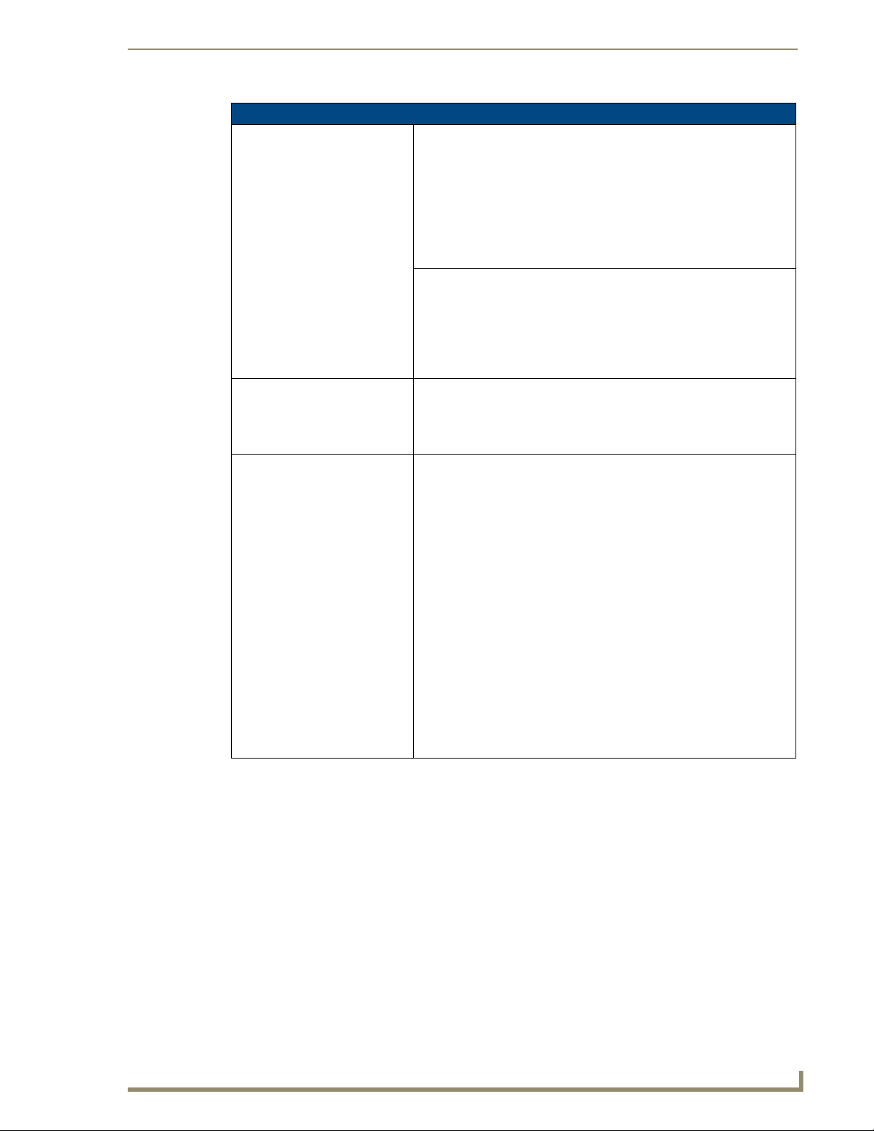
Front Panel Components:
Light sensor: • Photosensitive light detector for automatic adjustment of the panel
Motion sensor (PIR): • Proximity Infrared Detector to wake the panel when the panel is
Front setup access button: • Provides both access to the Setup and Calibration pages and toggles the
Microphone: • Used for intercom applications (requires an optional NXA-AVB/RGB or
Speakers: • Stereo output with a frequency response of 450 Hz - 7 KHz
Rear Panel Components: (Side panel location on NXD-Wall Mount panels)
RGB connector • This connector is only made available only by using an NXA-RGB
Audio/Video connector: • RJ-45 connector for communication of differential audio/video signals
Ethernet 10/100 port: • RJ-45 port for 10/100 Mbps communication. The Ethernet port
Ethernet 10/100 LEDs: • LEDs show communication activity and connection information:
brightness (a dim room results in a dimmer LCD display and a bright
room results in a brighter LCD display).
Note: The light sensor can be adjusted via the Sensor Setup Page section
on page 158.
approached.
• Activation range: +
20° vertically from center and + 45° horizontally
from center.
Note: The motion sensor can be adjusted via the Sensor Setup page
(Sensor Setup Page section on page 158).
panel between a "sleep" and "wake" state.
- When wired, "sleep" status means the backlight is Off.
- When battery operated, wireless "sleep" status means the touch panel
base is either Off or "suspended".
NXA-AVB/ETHERNET Breakout Box).
interface card installed within the touch panel. This card is sold either as
part of an RGB Kit configuration or within the NXA-RGBKIT upgrade kit
for previous Video Kit fitted VG-Series panels.
• Routes RGB and computer control pass-thru signals to/from a Modero
panel up to 200 ft. (60.9 m).
• RJ-45 connector provides RGB/Component video signals (being routed
from the rear RGB/Component input ports) and touch control information
to the RJ-45 RGB connector on the NXA-RGB card (installed within the
panel). This connector routes VGA and Component video signals.
to/from the touch panel (panel type dependant). This connector receives
Composite video, Stereo (left/right) audio, and microphone audio.
• Video is received via the NXA-AVB/RGB Breakout Box. Configuring
video windows for playback is done using TPDesign4.
• In-bound audio (from the Breakout Box) gets directed to the speakers.
• Out-bound audio is sent from the on-board microphone (on the
front-panel). Selecting audio files for playback is configured through
TPDesign4.
automatically negotiates the connection speed (10 Mbps or 100 Mbps),
and whether to use half duplex or full duplex mode.
®
• These panels communicate with the NetLinx
Master using the ICSP
protocol over Ethernet.
A-activity - Yellow LED lights when receiving or transmitting Ethernet
data packets.
L-link - Green LED lights when the Ethernet cables are connected and
terminated correctly.
4
VG-Series Modero Touch Panels
Page 15
Introduction
1200VG Panel Specifications (Cont.)
Rear Panel Components
(Cont.):
PWR connector: • 2-pin 3.5 mm mini-Phoenix connector.
Stereo Output connector: • Stereo output through a 3.5mm mini-jack (for use with external
USB connector (2): • The two Type-A USB ports can connect up to two external keyboard or
Mini-USB connector: • 5-pin Mini-USB connector used for programming, firmware update, and
Operating / Storage
Environment:
Included Accessories: • Installation Kit for 12" and 17" NXD panels (KA2251-01):
(Side panel location on NXD-Wall Mount panels)
speakers).
mouse devices for use with Virtual PC applications.
• These ports can be used to communicate to a PC and transfer pass-thru
touch control from the external devices, thru the NXA-AVB/RGB, to the
PC, and then back again. Refer to the Preparing your panel for Pass-
Thru Control (using the NXA-AVB/RGB Breakout Box) section on
page 26.
touch panel file transfer between the PC and the target panel.
Note: When connecting the panel to PC using a CC-USB (or compatible)
cable, be sure to power the panel On before attempting to connect the
USB cable from the PC to the mini-USB port on the panel.
Refer to the Step 5: Confirm and View the current AMX USB device
connections section on page 100 for more information.
• Operating Temperature: 10° C (50° F) to 40° C (104° F)
• Operating Humidity: 20% to 85% RH
• Storage Temperature: -20° C (-4° F) to 60° C (140° F)
• Storage Humidity: 5% to 85% RH
- 2-pin mini-Phoenix connector (41-5025)
- Four Drywall clips (62-5924-05) and #6 - sheet metal screws
- One CAT5 Suppression Ferrites (04-0014)
- Three Phillips-head screws (#4-20 x 0.250 Black)
• Installation Kit for 12" NXT panels (KA2251-03):
- 2-pin mini-Phoenix connector (41-5025)
- Three Phillips-head screws (#4-20 x 0.250 Black)
- Two CAT5 Suppression Ferrites (04-0014)
• Included within the RGB Kit (FGxxxx-xxRGB) is the following:
- Modero VG Touch Panel (NXD/NXT-1200/1500/1700VG)
- NXA-AVB/RGB Breakout Box (FG2254-11)
- NXA-RGB internal RGB/VGA Interface Card (FG2260)
- NXA-RGBCBL, 15-pin to 5X BNC RGB Breakout cable (FG2250-80)
- NXA-MTC/RGB Modero 10’ foot Table Top Cable
(with RGB connector) (CA2250-70)
• Included within the Video Kit (FGxxxx-xV) is the following:
- Modero VG Touch Panel (NXD/NXT-1200/1500/1700VG)
- Modero 10’ foot Table Top Cable (CA2250-50)
- NXA-AVB/ETHERNET Breakout Box (FG2254-10)
(included only on NXT models - optional with NXD models)
VG-Series Modero Touch Panels
5
Page 16
Introduction
1200VG Panel Specifications (Cont.)
Other AMX Equipment: Several items are included within both the Video and RGB Kits. Any items
not specifically included within those kits can be considered as optional
accessories.
• CB-TP12 (FG031-10): - 12" metallic conduit box for Wall Mount
installations.
• CC-USB (Type-A) to Mini-B 5-Wire programming cable (FG10-5965)
• Kensington Lock Bracket (FG2259-10) (optional only with NXTs)
• MAX-CSE MAX Video Encoder (FG2178-70)
• MB-TP12 Universal VESA Mounting Box for 12" WallMount panels
(FG031-50):
- Black metallic VESA back box (62-0031-50)
- Black plastic cover (with grommet opening) (60-0031-50)
- Four Phillips pan-head screws (#8-32 x 0.50 Black) (80-0146-02)
- Tie Wrap (Large) (45-0009A) (for use with NXA-MTC/RGB)
- Twelve Under-cut Phillips-head screws (#6-32 x 0.500 Black) (80-
0139)
- Strain relief grommet (45-0004-03) (for use with CA2250-50)
- Universal VESA Mount grommet (45-0032-01)
(for use with NXA-MTC/RGB)
• NXA-AVB/ETHERNET Breakout Box (FG2254-10)
- Also comes included within Video Kits.
• NXA-AVB/RGB Breakout Box (FG2254-11)
- Also comes included within RGB Kits.
• NXA-BASE/B (FG2255)
- Wireless base for Table Top touch panels (NXT models only).
• NXA-KLB Kensington Lock Kit for NXT panels (FG2259-10)
(optional only with NXT models)
• NXA-MTC/RGB Modero 10’ foot Table Top Cable (with RGB connector)
(CA2250-70). This cable is not wall-rated for NXD models.
• NXA-PCI80211G Wireless Card (FG2255-04)
• NXA-RGBKIT RGB upgrade kit for Composite Video touch panels
(FG2255-11):
- NXA-AVB/RGB Breakout Box (FG2254-11)
- NXA-MTC/RGB Modero 10’ foot Table Top Cable
(with RGB connector) (CA2250-70)
- NXA-RGB internal RGB/VGA Interface Card (FG2260)
- NXA-RGBCBL, 15-pin to 5X BNC RGB Breakout cable (FG2250-80)
- NXT Table Top replacement I/O plate (with RGB connector opening)
(62-2250-59)
- NXD WallMount replacement adhesive overlay for existing I/O plate
(53-2250-03)
• Note: The NXT replacement I/O plate is a single piece which is
meant to be swapped-out with the pre-existing plate shipped with
Composite Video panels. On NXD panels, the RGB connector
opening is pre-drilled into the I/O plate but can only be accessed by
replacing the adhesive cover and maintaining the existing overlay.
When upgrading NXD panels with this kit, don’t replace the NXD I/O
plate, only the adhesive cover.
• NXA-RGBCBL, 15-pin to 5X BNC RGB Breakout cable (FG2250-80)
• NXA-RK12 (FG2904-50)
- RackMount kit for 12" Wall Mount touch panels (NXD models only)
• NXT-BP (FG2250-10)
- Battery pack for Table Top panels. Provides 4 hours of continual
operation (NXT models only)
6
VG-Series Modero Touch Panels
Page 17
1200VG Panel Specifications (Cont.)
Other AMX Equipment (Cont): • NXT-CHG (FG2250-50)
- Battery charger for NXT-BP batteries. Charges batteries in 8 hours.
• Upgrade Compact Flash (factory programmed with firmware):
NXA-CFTPV256M - 256 MB V/VG compact flash card (FG2116-43)
NXA-CFTPV512M - 512 MB V/VG compact flash card (FG2116-44)
NXA-CFTPV1G - 1 GB V/VG compact flash card (FG2116-45)
Product Specifications (NXD-1500VG and NXT-1500VG)
The following table outlines the specifications for VG-Series of 15" Modero panels.
1500VG Panel Specifications
Dimensions (HWD): • NXD-1500VG (with faceplate): 14.37" x 15.20" x 3.31"
Power Requirements: • Constant current draw: 3.7 A @ 12 VDC (stand-alone)
Memory (factory default): • 256 MB on-board memory
Weight: • NXD-1500VG: 13.45 lbs (6.10 kg)
Panel LCD Parameters: • Aspect Ratio: 4 x 3
Viewing Angles: • Vertical: + 85° (up from center) and - 85° (down from center)
(36.50 cm x 38.61 cm x 8.40 cm)
• NXT-1500VG (Fully raised): 12.94" x 14.95" x 11.73"
(32.87 cm x 37.97 cm x 29.78 cm)
• NXT-1500VG (Fully lowered): 7.45" x 14.95" x 11.72"
(18.92 cm x 37.97 cm x 29.77 cm)
• CB-TP15 (conduit/wallbox): 13.48" x 14.18" x 3.49"
(34.24 cm x 36.00 cm x 8.85 cm)
• MB-TP15 (VESA mounting box): 14.37" x 15.19" x 3.59"
(36.50 cm x 38.59 cm x 9.12 cm)
• Startup current draw: 5.5 A @ 12 VDC (stand-alone)
• 128 MB Compact Flash (upgradeable to 1 GB factory programmed)
• NXT-1500VG: 17.15 lbs (7.78 kg)
• Brightness (luminance): 400 cd/m
• Channel transparency: 8-bit Alpha channel transparency
• Contrast ratio: 300:1
• Display area (HW): 304.13 mm x 228.10 mm
• Display colors: 16 million colors (24-bit color depth)
• Dot/pixel pitch: 0.297 mm
• Screen resolution (HW): 1024 x 768
• Video formats: NTSC, PAL, and SECAM (shown within variable-size
video windows)
2
Introduction
VG-Series Modero Touch Panels
7
Page 18
Introduction
1500VG Panel Specifications (Cont.)
Features: • Display of Component RGB/HDTV signals (done through the use of both
an internal NXA-RGB card and an external NXA-AVB/RGB Breakout
Box)
• Enhanced hardware security (via an externally mounted Kensington
Lock system)
• Ethernet connectivity (replaced ICSNet as a method of communication)
• New and improved connector compartment
• Pass-thru Computer Control (via the NXA-RGB card)
• Pre-installed 802.11g wireless card and integrated antennas
(NXT models only)
• RGB or Component input
• Streaming MPEG-2 and MPEG-4 digital video support
• Streaming MP2, MP3, and AAC digital audio support
• Support of the latest G4 applications: G4 Computer Control, G4Web
Control, Dynamo, TakeNote™, and PictureFrame™.
• USB mouse/keyboard/programming ports
• Wired Ethernet @10/100 and Wireless Ethernet 802.11g
Supported Audio Sample Rates: • 48000Hz, 44100Hz, 32000Hz, 24000Hz, 22050Hz, 16000Hz, 12000Hz,
11025Hz, and 8000Hz.
Certifications: • FCC Part 15 Class B, CE, and EN 60950
Supported Transport Protocols: • RTP (MPEG-2/MPEG-4 Transport Stream)
• UDP (MPEG-2 Transport Stream)
Supported Audio Codecs: • Advanced Audio Coding (AAC)
• MPEG Audio Level 2 (MP2)
• MPEG Audio Level 3 (MP3)
Supported Video Codecs: •MPEG-2
•MPEG-4
Button Assignments: Button assignments can only be adjusted in TPD4 and not on the panels.
• Button channel range: 1 - 4000 button push and Feedback (per address
port)
• Button variable text range: 1 - 4000 (per address port)
• Button states range: 1 - 256 (General Button; 1 = Off State, 2 = On State)
• Level range: 1 - 600 (default level value 0-255, can be set up to 1-65535)
• Address port range: 1 - 100
8
VG-Series Modero Touch Panels
Page 19
Introduction
1500VG Panel Specifications (Cont.)
Front Panel Components:
Light sensor: • Photosensitive light detector for automatic adjustment of the panel
Motion sensor (PIR): • Proximity Infrared Detector to wake the panel when the panel is
Front setup access button: • Provides both access to the Setup and Calibration pages and toggles the
Microphone: • Used for intercom applications (requires an optional NXA-AVB/RGB or
Speakers: • Stereo output with a frequency response of 450 Hz - 7 KHz
Rear Panel Components: (Side panel location on NXD-Wall Mount panels)
RGB connector • This connector is only made available only by using an NXA-RGB
Audio/Video connector: • RJ-45 connector for communication of differential audio/video signals
Ethernet 10/100 port: • RJ-45 port for 10/100 Mbps communication. The Ethernet port
Ethernet 10/100 LEDs: • LEDs show communication activity and connection information:
PWR connector: • 2-pin 3.5 mm mini-Phoenix connector.
Stereo Output connector: • Stereo output through a 3.5mm mini-jack (for use with external
brightness (a dim room results in a dimmer LCD display and a bright
room results in a brighter LCD display).
Note: The light sensor can be adjusted via the Sensor Setup Page section
on page 158.
approached.
• Activation range: +
from center.
Note: The motion sensor can be adjusted via the Sensor Setup
Page section on page 158.
panel between a "sleep" and "wake" state.
- When wired, "sleep" status means the backlight is Off.
- When battery operated, wireless "sleep" status means the touch panel
base is either Off or "suspended".
NXA-AVB/ETHERNET Breakout Box).
interface card installed within the touch panel. This card is sold either as
part of an RGB Kit configuration or within the NXA-RGBKIT upgrade kit
for previous Video Kit fitted VG-Series panels.
• Routes RGB and computer control pass-thru signals to/from a Modero
panel up to 200 ft. (60.9 m).
• RJ-45 connector provides RGB/Component video signals (being routed
from the rear RGB/Component input ports) and touch control information
to the RJ-45 RGB connector on the NXA-RGB card (installed within the
panel). This connector routes VGA and Component video signals.
to/from the touch panel (panel type dependant). This connector receives
Composite video, Stereo (left/right) audio, and microphone audio.
• Video is received via the NXA-AVB/RGB Breakout Box. Configuring
video windows for playback is done using TPDesign4.
• In-bound audio (from the Breakout Box) gets directed to the speakers.
• Out-bound audio is sent from the on-board microphone (on the
front-panel). Selecting audio files for playback is configured through
TPDesign4.
automatically negotiates the connection speed (10 Mbps or 100 Mbps),
and whether to use half duplex or full duplex mode.
• These panels communicate with the NetLinx Master using the ICSP
protocol over Ethernet.
A-activity - Yellow LED lights when receiving or transmitting Ethernet
data packets.
L-link - Green LED lights when the Ethernet cables are connected and
terminated correctly.
speakers).
20° vertically from center and + 45° horizontally
VG-Series Modero Touch Panels
9
Page 20
Introduction
1500VG Panel Specifications (Cont.)
Rear Panel Components
(Cont.):
USB connector (2): • The two Type-A USB ports can connect up to two external keyboard or
Mini-USB connector: • 5-pin Mini-USB connector used for programming, firmware update, and
Operating / Storage
Environment:
Included Accessories: • Installation Kit for 15" NXD panels (KA2251-02):
(Side panel location on NXD-Wall Mount panels)
mouse devices for use with Virtual PC applications.
• These ports can be used to communicate to a PC and transfer pass-thru
touch control from the external devices, thru the NXA-AVB/RGB, to the
PC, and then back again. Refer to the Preparing your panel for Pass-
Thru Control (using the NXA-AVB/RGB Breakout Box) section on
page 26.
touch panel file transfer between the PC and the target panel.
Note: When connecting the panel to PC using a CC-USB (or compatible)
cable, be sure to power the panel On before attempting to connect the
USB cable from the PC to the mini-USB port on the panel. Refer to the
Step 5: Confirm and View the current AMX USB device
connections section on page 100 for more information.
• Operating Temperature: 10° C (50° F) to 40° C (104° F)
• Operating Humidity: 20% to 85% RH
• Storage Temperature: -20° C (-4° F) to 60° C (140° F)
• Storage Humidity: 5% to 85% RH
- 2-pin mini-Phoenix connector (41-5025)
- Four Drywall clips (62-5924-05) and #6 - sheet metal screws
- Three Phillips-head screws (#4-20 x 0.250 Black)
- Two CAT5 Suppression Ferrites (04-0014)
• Installation Kit for 15" and 17" NXT panels (KA2251-04):
- 2-pin mini-Phoenix connector (41-5025)
- One CAT5 Suppression Ferrites (04-0014)
- Three Phillips-head screws (#4-20 x 0.250 Black)
• Included within the RGB Kit (FGxxxx-xxRGB) is the following:
- Modero VG Touch Panel (NXD/NXT-1200/1500/1700VG)
- NXA-AVB/RGB Breakout Box (FG2254-11)
- NXA-RGB internal RGB/VGA Interface Card (FG2260)
- NXA-RGBCBL, 15-pin to 5X BNC RGB Breakout cable (FG2250-80)
- NXA-MTC/RGB Modero 10’ foot Table Top Cable
(with RGB connector) (CA2250-70)
• Included within the Video Kit (FGxxxx-xV) is the following:
- Modero VG Touch Panel (NXD/NXT-1200/1500/1700VG)
- Modero 10’ foot Table Top Cable (CA2250-50)
- NXA-AVB/ETHERNET Breakout Box (FG2254-10)
10
VG-Series Modero Touch Panels
Page 21
Introduction
1500VG Panel Specifications (Cont.)
Other AMX Equipment: Several items are included within both the Video and RGB Kits. Any items
not specifically included within those kits are considered optional.
• CB-TP15 (FG032-10): 15" metallic conduit box for Wall Mount
installations.
• CC-USB (Type-A) to Mini-B 5-Wire programming cable (FG10-5965)
• Kensington Lock Bracket (FG2259-10) (optional only with NXTs)
• MAX-CSE MAX Video Encoder (FG2178-70)
• MB-TP15 Universal VESA Mounting Box for 15" WallMount panels
(FG032-50):
- Black metallic VESA back box (62-0032-50)
- Black plastic cover (with grommet opening) (60-0032-50)
- Four Phillips pan-head screws (#8-32 x 0.50 Black) (80-0146-02)
- Tie Wrap (Large) (45-0009A) (for use with NXA-MTC/RGB)
- Twelve Under-cut Phillips-head screws (#6-32 x 0.500 Black)
(80-0139)
- Strain relief grommet (45-0004-03) (for use with CA2250-50)
- Universal VESA Mount grommet (45-0032-01)
(for use with NXA-MTC/RGB)
• NXA-AVB/ETHERNET Breakout Box (FG2254-10)
- Also comes included within Video Kits.
• NXA-AVB/RGB Breakout Box (FG2254-11)
- Also comes included within RGB Kits.
• NXA-BASE/B (FG2255)
- Wireless base for Table Top touch panels (NXT models only).
• NXA-KLB Kensington Lock Kit for NXT panels (FG2259-10)
(optional only with NXT models)
• NXA-MTC/RGB Modero 10’ foot Table Top Cable (with RGB connector)
(CA2250-70). This cable is not wall-rated for NXD models.
Several items are included within both the Video and RGB Kits. Any items
not specifically included within those kits are considered optional.
• NXA-PCI80211G Wireless Card (FG2255-04)
• NXA-RGBKIT RGB upgrade kit for Composite Video touch panels
(FG2255-11):
- NXA-AVB/RGB Breakout Box (FG2254-11)
- NXA-MTC/RGB Modero 10’ foot Table Top Cable (with RGB
connector) (CA2250-70)
- NXA-RGB internal RGB/VGA Interface Card (FG2260)
- NXA-RGBCBL, 15-pin to 5X BNC RGB Breakout cable (FG2250-80)
- NXT Table Top replacement I/O plate (with RGB connector opening)
(62-2250-59)
- NXD WallMount replacement adhesive overlay for existing I/O plate
(53-2250-03)
Note: The NXT replacement I/O plate is a single piece which is meant
to be swapped-out with the pre-existing plate shipped with
Composite Video panels. On NXD panels, the RGB connector
opening is pre-drilled into the I/O plate but can only be accessed by
replacing the adhesive cover and maintaining the existing overlay.
When upgrading NXD panels with this kit, don’t replace the NXD I/O
plate, only the adhesive cover.
• NXA-RGBCBL, 15-pin to 5X BNC RGB Breakout cable (FG2250-80)
• NXA-RK15 (FG2904-51)
- RackMount kit for 15" Wall Mount touch panels (NXD models only)
VG-Series Modero Touch Panels
11
Page 22
Introduction
1500VG Panel Specifications (Cont.)
Other AMX Equipment (Cont.): • NXT-BP (FG2250-10)
- Battery pack for Table Top panels. Provides 4 hours of continual
operation (NXT models only)
• NXT-CHG (FG2250-50)
- Battery charger for NXT-BP batteries. Charges batteries in 8 hours.
• Upgrade Compact Flash (factory programmed with firmware):
NXA-CFTPV256M - 256 MB V/VG compact flash card (FG2116-43)
NXA-CFTPV512M - 512 MB V/VG compact flash card (FG2116-44)
NXA-CFTPV1G - 1 GB V/VG compact flash card (FG2116-45)
Product Specifications (NXD-1700VG and NXT-1700VG)
The following table outlines the specifications for VG-Series of 17" Modero panels.
1700VG Panel Specifications
Dimensions (HWD): • NXD-1700VG (with faceplate): 14.44" x 18.09" x 3.31"
Power Requirements: • Constant current draw: 4.5 A @ 12 VDC (stand-alone)
Memory (factory default): • 256 MB on-board memory
Weight: • NXD-1700VG: 18.20 lbs (8.26 kg)
Panel LCD Parameters: • Aspect Ratio: 16 x 9
Viewing Angles: • Vertical: + 85° (up from center) and - 85° (down from center)
(36.68 cm x 45.95 cm x 8.41 cm)
• NXT-1700VG (Fully raised): 13.29" x 17.84" x 12.44"
(35.31 cm x 45.31 cm x 31.60 cm)
• NXT-1700VG (Fully lowered): 6.23" x 17.84" x 12.44"
(15.82 cm x 45.31 cm x 31.60 cm)
• CB-TP17 (conduit/wallbox): 13.55" x 17.07" x 3.49"
(34.43 cm x 43.38 cm x 8.85 cm)
• MB-TP17 (VESA mounting box): 14.44" x 18.09" x 3.48"
(36.68 cm x 45.95 cm x 8.84 cm)
• Startup current draw: 6.5 A @ 12 VDC (stand-alone)
• 128 MB Compact Flash (upgradeable to 1 GB factory programmed)
• NXT-1700VG: 22.00 lbs (9.98 kg)
• Brightness: 450 cd/m
• Channel transparency: 8-bit Alpha channel transparency
• Contrast ratio: 600:1
• Display colors: 16 million colors (24-bit color depth)
• Dot/pixel pitch: 0.289 mm
• Screen resolution (HV): 1280 x 768 pixels XGA-Wide @ 60 HZ frame
frequency
• Video formats: NTSC, PAL, and SECAM (shown within variable-size
video windows)
2
12
VG-Series Modero Touch Panels
Page 23
Introduction
1700VG Panel Specifications (Cont.)
Features: • Display of Component RGB/HDTV signals (done through the use of both
an internal NXA-RGB card and an external NXA-AVB/RGB Breakout
Box)
• Enhanced hardware security (via an externally mounted Kensington
Lock system)
• Ethernet connectivity (replaced ICSNet as a method of communication)
• New and improved connector compartment
• Pass-thru Computer Control (via the NXA-RGB card)
• Pre-installed 802.11g wireless card and integrated antennas
(NXT models only)
• RGB or Component input
• Streaming MPEG-2 and MPEG-4 digital video support
• Streaming MP2, MP3, and AAC digital audio support
• Support of the latest G4 applications: G4 Computer Control, G4Web
Control, Dynamo, TakeNote™, and PictureFrame™.
• USB mouse/keyboard/programming ports
• Wired Ethernet @10/100 and Wireless Ethernet 802.11g
Supported Audio Sample Rates: • 48000Hz, 44100Hz, 32000Hz, 24000Hz, 22050Hz, 16000Hz, 12000Hz,
11025Hz, and 8000Hz.
Certifications: • FCC Part 15 Class B, CE, and EN 60950
Supported Transport Protocols: • RTP (MPEG-2/MPEG-4 Transport Stream)
• UDP (MPEG-2 Transport Stream)
Supported Audio Codecs: • Advanced Audio Coding (AAC)
• MPEG Audio Level 2 (MP2)
• MPEG Audio Level 3 (MP3)
Supported Video Codecs: •MPEG-2
•MPEG-4
Button Assignments: Button assignments can only be adjusted in TPD4 and not on the panels.
• Button channel range: 1 - 4000 button push and Feedback (per address
port)
• Button variable text range: 1 - 4000 (per address port)
• Button states range: 1 - 256 (General Button; 1 = Off State, 2 = On State)
• Level range: 1 - 600 (default level value 0-255, can be set up to 1-65535)
• Address port range: 1 - 100
VG-Series Modero Touch Panels
13
Page 24
Introduction
1700VG Panel Specifications (Cont.)
Front Panel Components:
Light sensor: • Photosensitive light detector for automatic adjustment of the panel
Motion sensor (PIR): • Proximity Infrared Detector to wake the panel when the panel is
Front setup access button: • Provides both access to the Setup and Calibration pages and toggles the
Microphone: • Used for intercom applications (requires an optional NXA-AVB/RGB or
Speakers: • Stereo output with a frequency response of 450 Hz - 7 KHz
Rear Panel Components: (Side panel location on NXD-Wall Mount panels)
RGB connector • This connector is only made available only by using an NXA-RGB
Audio/Video connector: • RJ-45 connector for communication of differential audio/video signals
Ethernet 10/100 port: • RJ-45 port for 10/100 Mbps communication. The Ethernet port
PWR connector: • 2-pin 3.5 mm mini-Phoenix connector.
Stereo Output connector: • Stereo output through a 3.5mm mini-jack (for use with external
Ethernet 10/100 LEDs: • LEDs show communication activity and connection information:
brightness (a dim room results in a dimmer LCD display and a bright
room results in a brighter LCD display).
Note: The light sensor can be adjusted via the Sensor Setup Page section
on page 158.
approached.
• Activation range: +
from center.
Note: The motion sensor can be adjusted via the Sensor Setup
Page section on page 158.
panel between a "sleep" and "wake" state.
- When wired, "sleep" status means the backlight is Off.
- When battery operated, wireless "sleep" status means the touch panel
base is either Off or "suspended".
NXA-AVB/ETHERNET Breakout Box).
interface card installed within the touch panel. This card is sold either as
part of an RGB Kit configuration or within the NXA-RGBKIT upgrade kit
for previous Video Kit fitted VG-Series panels.
• Routes RGB and computer control pass-thru signals to/from a Modero
panel up to 200 ft. (60.9 m).
• RJ-45 connector provides RGB/Component video signals (being routed
from the rear RGB/Component input ports) and touch control information
to the RJ-45 RGB connector on the NXA-RGB card (installed within the
panel). This connector routes VGA and Component video signals.
to/from the touch panel (panel type dependant). This connector receives
Composite video, Stereo (left/right) audio, and microphone audio.
• Video is received via the NXA-AVB/RGB Breakout Box. Configuring
video windows for playback is done using TPDesign4.
• In-bound audio (from the Breakout Box) gets directed to the speakers.
• Out-bound audio is sent from the on-board microphone (on the
front-panel). Selecting audio files for playback is configured through
TPDesign4.
automatically negotiates the connection speed (10 Mbps or 100 Mbps),
and whether to use half duplex or full duplex mode.
• These panels communicate with the NetLinx Master using the ICSP
protocol over Ethernet.
speakers).
A-activity - Yellow LED lights when receiving or transmitting Ethernet
data packets.
L-link - Green LED lights when the Ethernet cables are connected and
terminated correctly.
20° vertically from center and + 45° horizontally
14
VG-Series Modero Touch Panels
Page 25
Introduction
1700VG Panel Specifications (Cont.)
Rear Panel Components
(Cont.):
USB connector (2): • The two Type-A USB ports can connect up to two external keyboard or
Mini-USB connector: • 5-pin Mini-USB connector used for programming, firmware update, and
Operating / Storage
Environment:
Included Accessories: • Installation Kit for 12" and 17" NXD panels (KA2251-01):
(Side panel location on NXD-Wall Mount panels)
mouse devices for use with Virtual PC applications.
• These ports can be used to communicate to a PC and transfer pass-thru
touch control from the external devices, thru the NXA-AVB/RGB, to the
PC, and then back again. Refer to the Preparing your panel for Pass-
Thru Control (using the NXA-AVB/RGB Breakout Box) section on
page 26.
touch panel file transfer between the PC and the target panel.
Note: When connecting the panel to PC using a CC-USB (or compatible)
cable, be sure to power the panel On before attempting to connect the
USB cable from the PC to the mini-USB port on the panel. Refer to the
Step 5: Confirm and View the current AMX USB device
connections section on page 100 for more information.
• Operating Temperature: 10° C (50° F) to 40° C (104° F)
• Operating Humidity: 20% to 85% RH
• Storage Temperature: -20° C (-4° F) to 60° C (140° F)
• Storage Humidity: 5% to 85% RH
- 2-pin mini-Phoenix connector (41-5025)
- Four Drywall clips (62-5924-05) and #6 - sheet metal screws
- One CAT5 Suppression Ferrites (04-0014)
- Three Phillips-head screws (#4-20 x 0.250 Black)
• Installation Kit for 15" and 17" NXT panels (KA2251-04):
- 2-pin mini-Phoenix connector (41-5025)
- One CAT5 Suppression Ferrites (04-0014)
- Three Phillips-head screws (#4-20 x 0.250 Black)
• Included within the RGB Kit (FGxxxx-xxRGB) is the following:
- Modero VG Touch Panel (NXD/NXT-1200/1500/1700VG)
- NXA-AVB/RGB Breakout Box (FG2254-11)
- NXA-RGB internal RGB/VGA Interface Card (FG2260)
- NXA-RGBCBL, 15-pin to 5X BNC RGB Breakout cable (FG2250-80)
- NXA-MTC/RGB Modero 10’ foot Table Top Cable
(with RGB connector) (CA2250-70)
• Included within the Video Kit (FGxxxx-xV) is the following:
- Modero VG Touch Panel (NXD/NXT-1200/1500/1700VG)
- Modero 10’ foot Table Top Cable (CA2250-50)
- NXA-AVB/ETHERNET Breakout Box (FG2254-10)
VG-Series Modero Touch Panels
15
Page 26

Introduction
1700VG Panel Specifications (Cont.)
Other AMX Equipment: Several items are included within both the Video and RGB Kits. Any items
not specifically included within those kits are considered optional.
• CB-TP17 (FG034-10): 17" metallic conduit box for Wall Mount
installations.
• CC-USB (Type-A) to Mini-B 5-Wire programming cable (FG10-5965)
• Kensington Lock Bracket (FG2259-10) (optional only with NXTs)
• MAX-CSE MAX Video Encoder (FG2178-70)
• MB-TP17 Universal VESA Mounting Box for 17" WallMount panels
(FG033-50):
- Black metallic VESA back box (62-0033-50)
- Black plastic cover (with grommet opening) (60-0033-50)
- Four Phillips pan-head screws (#8-32 x 0.50 Black) (80-0146-02)
- Tie Wrap (Large) (45-0009A) (for use with NXA-MTC/RGB)
- Ten Under-cut Phillips-head screws (#6-32 x 0.500 Black) (80-0139)
- Strain relief grommet (45-0004-03) (for use with CA2250-50)
- Universal VESA Mount grommet (45-0032-01)
(for use with NXA-MTC/RGB)
• NXA-AVB/ETHERNET Breakout Box (FG2254-10)
- Also comes included within Video Kits.
• NXA-AVB/RGB Breakout Box (FG2254-11)
- Also comes included within RGB Kits.
• NXA-BASE/B (FG2255)
- Wireless base for Table Top touch panels (NXT models only)
• NXA-KLB Kensington Lock Kit for NXT panels (FG2259-10)
(optional only with NXT models)
• NXA-MTC/RGB Modero 10’ foot Table Top Cable (with RGB connector)
(CA2250-70). This cable is not wall-rated for NXD models.
• NXA-PCI80211G Wireless Card (FG2255-04)
• NXA-RGBKIT RGB upgrade kit for Composite Video touch panels
(FG2255-11):
- NXA-AVB/RGB Breakout Box (FG2254-11)
- NXA-MTC/RGB Modero 10’ foot Table Top Cable
(with RGB connector) (CA2250-70)
- NXA-RGB internal RGB/VGA Interface Card (FG2260)
- NXA-RGBCBL, 15-pin to 5X BNC RGB Breakout cable (FG2250-80)
- NXT Table Top replacement I/O plate (with RGB connector opening)
(62-2250-59)
- NXD WallMount replacement adhesive overlay for existing I/O plate
(53-2250-03)
Note: The NXT replacement I/O plate is a single piece which is meant
to be swapped-out with the pre-existing plate shipped with
Composite Video panels. On NXD panels, the RGB connector
opening is pre-drilled into the I/O plate but can only be accessed by
replacing the adhesive cover and maintaining the existing overlay.
When upgrading NXD panels with this kit, don’t replace the NXD I/O
plate, only the adhesive cover.
• NXA-RGBCBL, 15-pin to 5X BNC RGB Breakout cable (FG2250-80)
• NXA-RK17 (FG2904-52)
- RackMount kit for 17" Wall Mount touch panels (NXD models only).
• NXT-BP (FG2250-10)
- Battery pack for Table Top panels. Provides 4 hours of continual
operation (NXT models only)
• NXT-CHG (FG2250-50
- Battery charger for NXT-BP batteries. Charges batteries in 8 hours.
)
16
VG-Series Modero Touch Panels
Page 27
1700VG Panel Specifications (Cont.)
Other AMX Equipment (Cont.): • Upgrade Compact Flash (factory programmed with firmware):
NXA-CFTPV256M - 256 MB V/VG compact flash card (FG2116-43)
NXA-CFTPV512M - 512 MB V/VG compact flash card (FG2116-44)
NXA-CFTPV1G - 1 GB V/VG compact flash card (FG2116-45)
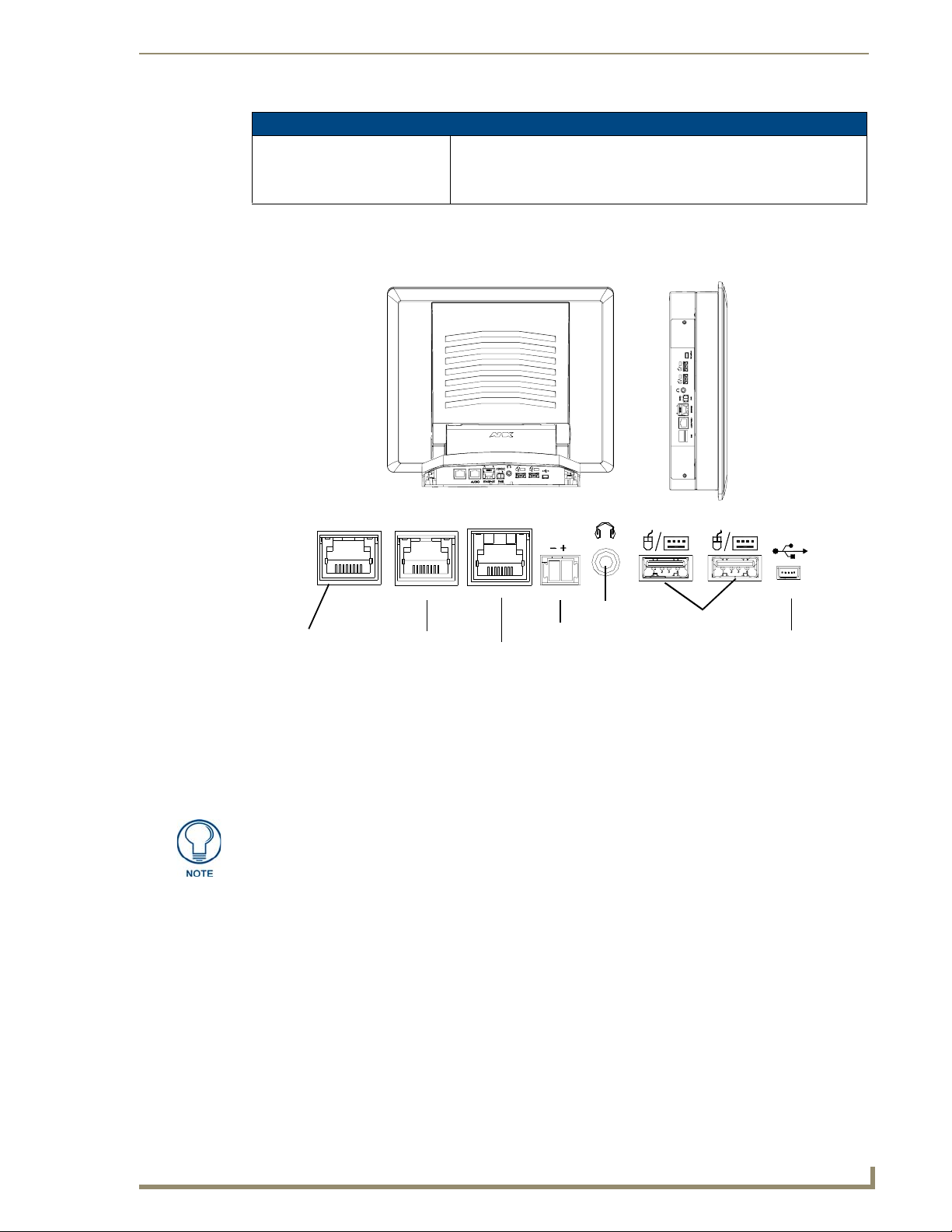
VG-Series Modero Connectors
FIG. 1 shows the connectors on the VG-Series Modero panels.
Introduction
NXT VG-Series
connectors located on
rear panel of the base
RGB
Composite/RGB
and pass-thru
control (CAT5)
Connector layout on sample VG-Series Video Touch Panels (RGB connector available with RGB Kit)
FIG. 1
AUDIO/VIDEO
Audio-Video from
NXA-AVB/RGB
(CAT5)
RGB
A
ETHERNET
Ethernet
(CAT5)
L
12VDC
PWR
Power
Stereo
Output
Keyboard/Mouse
USB connectors (2)
NXD VG-Series
connectors located
on left side panel
PROGRAM
Mini-USB
(Program Port)
Connecting and Using USB Input Devices
These panels can have up to two USB-capable input devices connected for use both on its different
firmware and TPD4 panel pages. These input devices can consist of a keyboard or mouse.
USB-connected input devices are detected and recognized by the panel upon
connection. Refer to the Configuring and Using USB with a Virtual
Master section on page 95 for more information on using a USB connection.
1. Insert the input device USB connectors into the appropriate USB connector on the panel.
2. Press the on-screen Reboot button (Protected Setup page) to save any changes and restart the panel.
3. After the panel splash-screen disappears:
If a USB mouse has been connected, a mouse cursor appears on the panel screen and its
location corresponds to the mouse cursor position sent by the external USB mouse.
If a USB keyboard has been connected, only on-screen keyboards and keypads will reflect any
external keystrokes sent from the external USB keyboard.
VG-Series Modero Touch Panels
17
Page 28

Introduction
Cleaning the Touch Overlay
You should clean the touch screen overlay after each day’s use.
Always use clean cotton cloths and a spray bottle containing water.
18
VG-Series Modero Touch Panels
Page 29
Touch Panel Accessories
Overview
The following section outlines and describes both the included accessories and other AMX equipment
available for both the Video and Video/RGB models of touch panels.
When working with firmware, it is important to note that version 1.xx of firmware
should only be loaded onto box’s using 1.xx series firmware. The version 2.xx
firmware should only be loaded onto box's running 2.xx series firmware.
To confirm the box’s current firmware version, you can either navigate to the BOB
Version field on the RGB Adjustment page or launch NetLinx Studio and open the
Online Tree tab.
Modero-VG touch panel firmware 2.60.27 or higher is required to download v2.xx
firmware into the break out box.
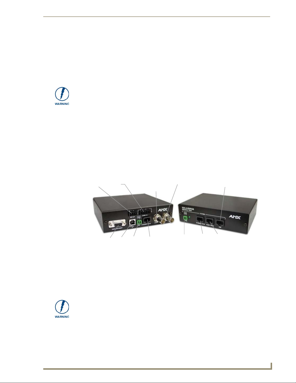
NXA-AVB/RGB Breakout Box (FG2254-11)
The NXA-AVB/RGB Ethernet/RGB Breakout Box allows any of AMX’s VG-Series Modero Touch
Panels to accept and display both RGB or HDTV Component signals directly from an external source.
Through this single connection point, the 12”, 15” and 17” VG-Series Modero panels experience
comprehensive connectivity for audio/video distribution, power, Ethernet connectivity, and RGB. FIG. 2
shows the NXA-AVB/RGB Breakout Box.
Touch Panel Accessories
Luma
S-Video Chroma
Power
(to panel)
RGB (to internal NXA-RGB card)
Ethernet
(to panel)
Audio/Video
(to panel)
(front)
In
Audio
In
USB
Mic Out
(rear)
RGB/Component
FIG. 2 NXA-AVB/RGB Breakout Box (front and rear views)
Power
Composite/
S-Video
Ethernet In
The NXA-AVB/RGB Breakout Box is available either separately or as part of AMX’s exclusive RGB
Kit (NXA-RGBKIT). The RGB Breakout Box (combined with the panel’s internal NXA-RGB interface
card) allows the Modero to accept and display high-bandwidth and high-quality RGB and HDTV
Component video signals. The NXA-AVB/RGB stands out amongst all previous AMX Breakout Boxes
in that it is firmware upgradeable, feeds high quality video signals via RJ-45 cables, and provides
keyboard and mouse pass-through functionality via the rear USB connector.
If the PWR/Activity LED (on the front of the unit) is blinking rapidly, this indicates there
is currently an activity in progress (such as a download). DO NOT unplug the unit
during a download as long as the LED is blinking in this manner.
VG-Series Modero Touch Panels
19
Page 30
Touch Panel Accessories
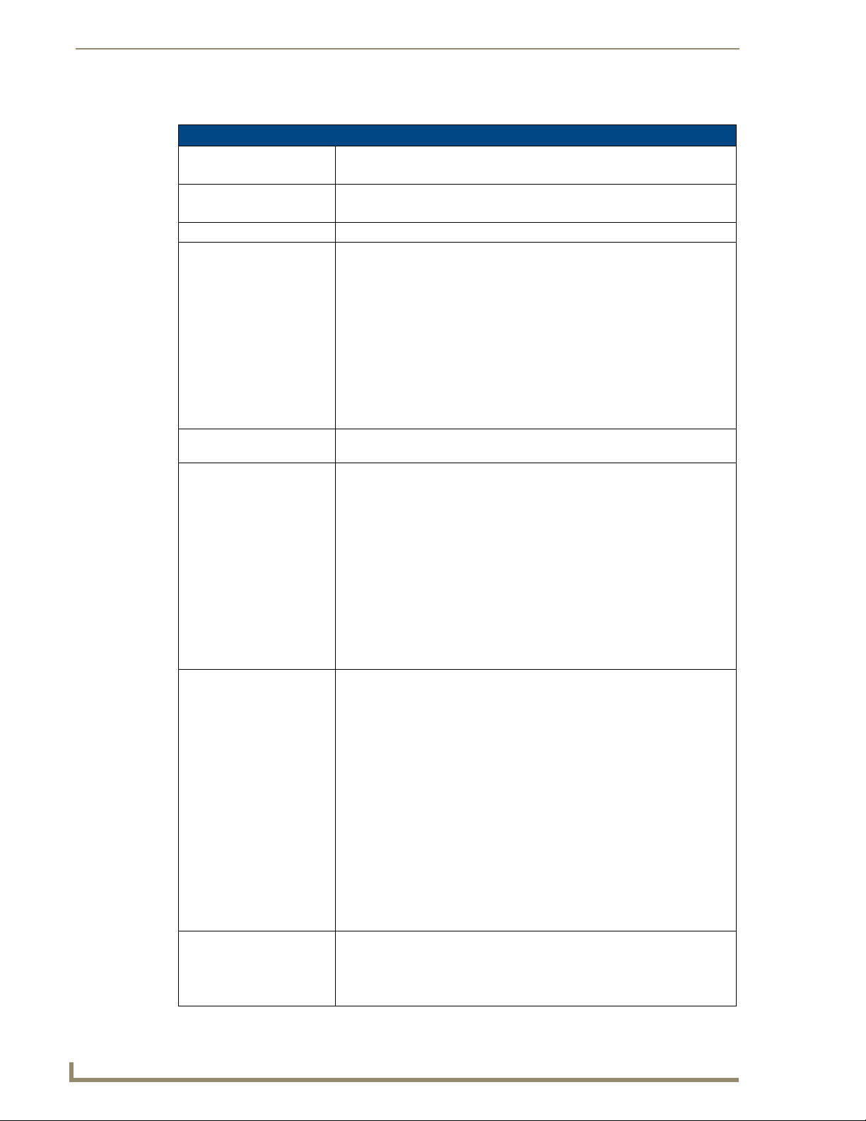
Product Specifications
NXA-AVB/RGB Specifications
Dimensions (HWD): • 1.52" x 5.54" x 4.93" (3.86 cm x 14.07 cm x 12.52 cm)
Power Consumption: • 240mA
Certifications: • FCC Part 15 Class B, CE, and EN60950
Features: • Accepts either Composite or S-Video inputs (1200V or VG-Series panels)
Availabili ty : • This unit is included with VG-Series panels using RGB Kits and as part of the
Front Components: • 2-pin 3.5 mm mini-Phoenix connector for power to the touch panel
Rear Components: • 4-pin 3.5 mm mini-Phoenix connector for out-bound audio (from microphone)
Included Accessories: • 4-pin 3.5 mm mini-Phoenix connector (41-5047)
• Width when attached to mounting ears: 6.65" (16.86 cm)
• Routed through AVB using a 12 VDC-compliant power supply
• Accepts RGB or Component inputs
• Integrates USB Type-B connector for keyboard and mouse communication
from the panel through to the PC
• Accepts 6-wire stereo audio with 4-wire microphone output
• Provides video/audio distribution to the video-capable panels over CAT5
cable up to 200 ft. (60.9 m)
• Provides audio distribution to audio-capable touch panels over a CAT5 cable
up to 200 ft. (60.9m)
• Routes RGB and computer control pass-thru signals to/from a Modero panel
up to 200 ft. (60.9 m)
NXA-RGBKIT upgrade kit.
• Green LED provides an indication of both power and activity
- 1 blink/second indicates the unit is powered and active
- Multiple blinks/second indicates there is currently an activity in progress,
such as a download. Do not unplug the unit during this process.
• RJ-45 connector provides Ethernet signals to the touch panel
• RJ-45 connector provides differential audio/video signals between the touch
panel and the box. This connector routes Composite video, Stereo (left/right)
audio, and microphone audio.
• RJ-45 connector provides RGB/Component video signals (being routed from
the rear RGB/Component input ports) and touch control information to the
RJ-45 RGB connector on the NXA-RGB card (installed within the panel).
This connector routes VGA and Component video signals.
• 6-pin 3.5 mm mini-Phoenix connector for in-bound (left/right channel) audio
• HD-15 D-Sub RGB/VGA/Component connector used to route an RGB
(computer) or Component (DVD/HDTV) signal to a target Modero panel
(using the internal NXA-RGB card).
• Type-B USB device port input connector for pass-thru computer control (by
connecting an external keyboard or mouse device for use with different PC
applications). The touch signals are routed to the touch panel via the front
RGB RJ-45 connector. Touch information is sent to and from the panel via
this two-way connector.
• 2-pin 3.5 mm mini-Phoenix connector for in-bound power (from a
12 VDC-compliant power supply)
• RJ-45 connector for Ethernet input from the control system
• BNC connector (female) for Composite or Chroma (COMP/Y). Composite
NTSC, PAL and SECAM video is provided via this connector.
• BNC connector (female) for luminance (C).
• 6-pin 3.5 mm mini-Phoenix connector (41-5063)
• Rack Mount Kit (KA2250-40) with mounting bracket (62-2254-02)
• Two 2-pin 3.5 mm mini-Phoenix connectors (41-5025)
20
VG-Series Modero Touch Panels
Page 31

Touch Panel Accessories
NXA-AVB/RGB Specifications (Cont.)
Other AMX Equipment: • AC-RK Equipment Rack Kit (FG575)
• NXA-MTC/RGB Combo Table Top cable (CA2250-70)
• NXA-RGBCBL, 15-pin to 5X BNC RGB Breakout cable (FG2250-80)
RGB RJ-45 connection and wiring information
This RJ-45 connector is used to route the signals connected to the RGB / Component input port on the
rear of the AVB/RGB Breakout Box to the VG-Series Modero panel. Standard CAT5 cable can be used
for this connection with short cable runs under 50 feet (15.24 m). For cable runs over 50 feet (15.24 m),
AMX recommends using the Belden Brilliance VideoTwist 7987. This Belden cable is not CAT5
compliant, but is designed to control skew between the red, green, and blue video signals. Therefore, for
longer cable runs, the video quality will be much higher using the Belden VideoTwist 7987 cable versus
standard CAT5 (or other Ethernet compliant cables). The pinout of this RGB connector is given in the
table below.
The Belden cable only adjusts for RGB skew but may still need to be configured
properly for cable length by using the Cable Variance setting on the RGB Adjustment
page (Video Adjustment - RGB Adjustment Page section on page 142).
RGB RJ-45 Connector Pinouts and Signals
Pin Color Function Polarity
1 Orange-White Blue Video -
2 Orange Blue Video +
3 Green-White Data
(bidirectional)
4 Blue Green Video -
5 Blue-White Green Video +
6 Green Data
(bidirectional)
7 Brown-White Red Video -
8 Brown Red Video +
-
+
It is important that the correct pairing is observed.
TIA 568B
VG-Series Modero Touch Panels
21
Page 32

Touch Panel Accessories
Using the HD-15 high-density connector
Connect the RGB/Comp source equipment HD-15 (male) connector to the RGB/COMPONENT HD-15
high-density connector (female) on the rear of the NXA-AVB/RGB Breakout Box. The following table
below lists the HD-15 connector pinouts.
HD-15 Connector Pinouts
Pin Signal Function
1 Red Red signals/Cr
2 Green Green signals/Y
3 Blue Blue signals/Cb
4 N/A Not used
5 GND Signal Ground
6 RAGND Red analog ground
7 GAGND Green analog ground
8 BAGND Blue analog ground
9 N/A Not used
10 SAGND Synchronization analog ground
11 N/A Not used
12 N/A Not used
13 HSYNC Horizontal synchronization signal
14 VSYNC Vertical synchronization signal
15 N/A Not used
5
1
HD-15 (male)
10
6
connector
15
11
Installing the NXA-AVB/RGB
A 12 VDC-compliant power supply can indirectly provide power to a Modero panel by routing power
through the NXA-AVB/RGB Breakout Box. FIG. 3 shows a sample wiring configuration using both an
indirect or direct power connection for a VG-Series Modero panel.
12 VDC power
supply
Indirect
Connect
Ethernet
Video In
(BNC)
Audio In
(6-pin)
(RJ-45)
Mic Out
(4-pin)
USB
(pass-thru)
Line Level out
(to amplifier
or VOL card)
RGB In (HD-15)
(rear)
NXA-AVB/RGB
Breakout Box
Power
supplied via
Breakout Box
12 VDC power
supply
Direct
Connect
Ethernet
(CAT5)
Audio/Video
(CAT5)
or
VG-Series and Video-capable
RGB (RGB and touch
control) (CAT5)
(front)
Touch Panels
22
FIG. 3
Sample Wiring configuration using the NXA-AVB/RGB Breakout Box
VG-Series Modero Touch Panels
Page 33

Touch Panel Accessories
The breakout box unit can be mounted on either a horizontal flat surface or into an
equipment rack (by removing the front screws and attaching it to an optional AC-RK).
The power supply being used on the NXA-AVB/RGB is dependant on the power
requirements of the target touch panel.
Use the NXA-MTC/RGB Combo Table Top cable (CA2250-70) to provide both communication and
10/100 network connectivity between the panel, NXA-AVB/RGB, NetLinx Master, and the network.
Wiring the NXA-AVB/RGB connectors and cables
The inputs and outputs on this breakout box are separated into front and rear connectors. The rear
connectors are used to input external signals. The front connectors are used to communicate signals
between the NXA-AVB/RGB and a target Modero panel.
The front RGB RJ-45 connector both receives one-way RGB video signals from the breakout box and
uses this same connector as a two-way communication point for pass-thru control data from the panel’s
USB connector through to the communicating computer. The NXA-MTC/RGB Combo Table Top cable
(CA2250-70) provides an RJ-45 Ethernet connector for data, an RJ-45 connector for Audio/Video, and a
third RJ-45 connector for both pass-thru control and RGB signal feed to the panel’s internal NXA-RGB
input card. FIG. 4 provides a layout of the wiring connection both into and from the breakout box.
RGB/Component In
(HD-15)
R
O
N
NXA-AVB/RGB
Breakout
Box
Microphone Out
(4-pin captive wire)
Audio In - Left Channel
(6-pin captive wire)
Audio In - Right Channel
(6-pin captive wire)
GND
Out (-)
Out (+)
GND
In (-)
In (+)
GND
In (-)
In (+)
USB
(Type-B)
12 VDC power
supply
FIG. 4 NXA-AVB/RGB Breakout Box connector wiring diagram
Ethernet
(RJ-45)
Comp/Y (BNC)
C (BNC)
R
E
A
R
The rear-panel wiring connections are described below (from left to right):
F
T
RGB
(CAT5)
Audio/Video
(CAT5)
Ethernet
Out (CAT5)
Powe r to
touch
panel
VG-Series Modero Touch Panels
• RGB/COMPONENT In: 15-pin HD 15 video connector used to feed in signals from an outside
video source, through the box, and then to NXA-RGB card on the
panel. This signal can also be fed from a BNC connector by using the
optional NXA-RGBCBL, 15-pin to 5X BNC RGB Breakout cable
(FG2250-80).
23
Page 34

Touch Panel Accessories
• MIC OUT: 4-pin mini-Phoenix connector, divided into GND, OUT-, and OUT+
terminal connectors.
An example of this cable is to strip the terminal ends of a 3.5mm
mini-jack and insert them into their respective locations on the Mic
Out port. This signal can be fed as a Line Level In to either an
amplifier or an AMX VOL card.
Either a balanced (+, -, and GND) or unbalanced (+ and GND) audio
signal can be connected to this output.
• AUDIO IN: 6-pin 3.5 mm mini-Phoenix connector, divided into left and right audio
channels. Each channel is divided into GND, IN+, and IN- terminal
cable connectors (2 sets of 3 for each channel).
An example of this cable is to strip the ends of 2 RCA audio cables
and insert them into their respective locations on the Audio In port.
Either a balanced (+, -, and GND) or unbalanced (+ and GND) audio
signal can be connected to this input.
•USB: Type-B USB device port input connector for pass-thru computer
control. This port provides two-way signal between the keyboard and
mouse (connected to the rear/side USB connectors on the Modero
panel) through the front RGB connector on the breakout box, out the
rear USB Type-B connector, and then to/from the connected
computer.
•PWR: 2-pin 3.5 mm mini-Phoenix connector that connects to a
12 VDC-compliant power supply. This port can be used to provide
power to a Modero panel by sending it through the NXA-AVB/RGB
(rear power connector through to the front power connector).
• ETHERNET: RJ-45 connector routes data to the G4 panel through the front
Ethernet port. These connections use a standard CAT5 Ethernet
cable to provide communication between the target panel, box, and
Master.
• Video In BNCs: Feeds either Composite/S-Video Luma or S-Video Chroma signals
into the NXA-AVB/RGB. This feed is then redirected out to a Modero
panel through the front Audio/Video CAT5 port.
Note: Although the NXA-AVB/RGB Breakout Box can accept either a
Composite or S-Video input signal type, only one input source can be
used at a time. This unit does not auto-detect the incoming signal
type. Using S-Video would require a cable split and a simultaneous
connection to both the COMP/Y and C connectors (which would
prevent an additional Composite signal from being fed into the unit).
A user should not try to connect two Composite video signal cables to
the COMP/Y and C connectors.
24
Wiring the NXA-AVB/RGB for Unbalanced Audio
Most domestic audio equipment has unbalanced audio inputs and outputs. This means that the audio
output (left, right, or mono) appears on a single wire, and is referenced to "0 V" or "Ground". Typical
connectors used are RCA "phono" connectors, DIN plugs/sockets, and 0.25" (6.3mm) or 3.5mm jack
plugs/sockets.
Unbalanced audio is adequate for most domestic environments and for line-level signals in a typical
broadcast studio. Problems may occur if the signals are carried over long distances, especially if the
source and destination have separate main supplies. Use the following wiring drawing (FIG. 5) to
configure an unbalanced audio connection.
When using unbalanced audio for the AUDIO IN connector (FIG. 5), the "-" and the "GND" terminals
should be connected together and then connected to the GND of the unbalance audio signal. When
connecting to an unbalanced audio input from the MIC OUT connector (FIG. 5), wire the "+" terminal to
the signal input, and the "GND" terminal to the signal ground.
VG-Series Modero Touch Panels
Page 35

Touch Panel Accessories
GND
IN-
IN+
GND
IN-
IN+
AUDIO IN
MIC OUT
GND
OUT-
OUT+
Wiring the rear AUDIO IN and MIC OUT for use with Unbalanced Audio
FIG. 5
Left Channel
Right Channel
Microphone
Unbalanced IN
(Jumper IN- to GND)
Unbalanced IN
(Jumper IN- to GND)
Unbalanced OUT
Wiring the NXA-AVB/RGB for Balanced Audio
Professional audio equipment will often use balanced audio inputs and outputs, usually on 3-pin "XLR"
connectors. A balanced audio signal consists of a pair of wires carrying the audio signal in anti-phase
with each other (if one wire carries a positive voltage, the other carries an equal and opposite negative
voltage).
The advantage of balanced audio over unbalanced audio is its ability to reject external interference added
as the signal is carried over the wire. The receiving equipment takes the voltage difference between the
two wires as the input signal. Interference will usually get added to both wires equally, and so gets
cancelled by the receiving equipment.
The 3 wires used in a typical XLR lead are often referred to as Ground, Live (Hot) and Return (Cold).
"Live" and "Return" carry the "in-phase" and "out-of-phase" versions of the audio respectively. The pins
of the XLR plug/socket are as follows:
• X = Ground
• L = Live (Hot)
• R = Return (Cold)
When connecting the MIC OUT connector to a balanced audio input (FIG. 6), use all three audio
terminals (+, -, and GND), then connect the "+" terminal to the "live" signal, the "-" terminal to the
"return" signal, and the "GND" terminal to the ground signal.
GND
OUT-
OUT+
Wiring the rear MIC OUT connector for use with Balanced Audio
FIG. 6
Ground signal
Return signal
Line signal
Balanced OUT
VG-Series Modero Touch Panels
25
Page 36

Touch Panel Accessories
Preparing your panel for Pass-Thru Control (using the NXA-AVB/RGB Breakout Box)
Pass-thru control allows the NXA-AVB/RGB to act as a control bridge between the USB input signals
(coming from a touch panel via the NXA-RGB card) and a target computer.
Pass-thru must be enabled to control devices through the NXA-RGB card when using
USB-compatible control devices.
Refer to the following commands to enable pass-thru on the RGB card: ^MPS on
page 225 for Mouse pass-thru and ^KPS on page 225 for the keyboard
pass-thru.
The two available USB input connections on the touch panel can be used to provide either Keyboard
and/or Mouse signals between the PC and the panel. You are no longer limited to one mouse and one
keyboard. You can use USB hubs and multiple mice/keyboards in any configuration.
When setting up pass-thru computer control its important to focus on the following areas:
1. Properly connect the NXA-AVB/RGB to both a target PC and touch panel using the appropriate
2. Enable pass-thru via the use of either the ^MPS or ^KPS commands (page 225).
3. Set up a touch panel page (via TPDesign4) with the necessary Video Fill >
The pass-thru is routed from the USB Input device, through the panel, then through internal
NXA-RGB card and to the front RGB RJ-45 connector on the NXA-AVB/RGB. From there
the signal is routed through the rear USB port on the breakout box and finally to the target PC.
Refer to FIG. 7 for a visual representation.
cabling. Refer to the following Wiring for Pass-Thru Computer Control section on page 27 for more
detailed information.
(Component/RGB video) properties selected.
Video Fill allows you to select from a drop-down list of video formats that are supported by the
touch panel specified in your project. VG-Series Modero panels (1200VG, 1500VG and 1700VG)
support Composite video, Component/RGB video, and Streaming video formats.
Selecting Component/RGB allows you to route a video signal from your computer
through the NXA-AVB/RGB and then to the panel.
Selecting Streaming Video requires that you enter the URL or IP Address of the
server that will provide the video stream.
Note that Streaming Source is only available as a Video Fill option if the project
specifies a touch panel that supports streaming video (NXD/NXT-1200VG,
NXD/NXT-1500VG, and NXD/NXT-1700VG only).
Set up a touch panel page (via TPDesign4) with the necessary Video Touch Pass-thru property
4.
(yes) selected.
Video Pass-Thru allows you to pass touch/control information from a touch input
device (touch panel, mouse or keyboard) through an NXA-AVB/RGB to a controlled
device with video-out capabilities. Select Ye s from the drop-down menu to enable
video pass-thru (disabled by default). This feature is also used in conjunction with
the ^MPS (mouse pass-thru) and ^KPS (keyboard pass-thru) commands.
26
VG-Series Modero Touch Panels
Page 37

Touch Panel Accessories
Wiring for Pass-Thru Computer Control
1.
Discharge any acquired static electricity by touching a grounded metal object.
2. Turn-off your computer and remove any installed power cables. Review FIG. 7 for an overview of
the overall wiring configuration surrounding pass-thru control.
RGB/Component In
PC
USB
(Type-A)
12 VDC power
supply
FIG. 7 Pass-thru control wiring configuration
(HD-15)
USB
(Type-B)
Ethernet
(RJ-45)
R
E
A
R
F
R
O
N
T
NXA-AVB/RGB
Breakout
Box
RGB
(CAT5)
Ethernet
Out (CAT5)
Powe r t o
touch panel
P
A
N
E
L
3. Use an HD-15 video cable to create a connection between the computer’s video output connector
and the HD-15 D-Sub RGB/VGA/Component connector on the rear of the NXA-AVB/RGB.
This HD-15 D-Sub RGB/VGA/Component connector on the breakout box is used to route an RGB
(computer) or Component (DVD/HDTV) signal to a target Modero panel (using the internal
NXA-RGB card).
4. Use a Type-A to Type-B USB cable to create a connection from USB connector on the computer to
the rear Type-B USB device port input connector on the rear of the NXA-AVB/RGB.
This connection routes pass-thru computer control from the touch panel, to the front RGB RJ-45
connector, and then through the rear USB port to the PC. Touch information is sent to and from the
panel via this two-way connector.
5. Verify the panel has been configured to communicate by connecting an RJ-45 10/100baseT Ethernet
connector from the rear Ethernet port on the breakout box to a valid Ethernet Hub.
6. Connect the incoming power connector to the 12 VDC power connector on the rear of the box.
DO NOT CONNECT POWER UNTIL THE UNIT IS COMPLETELY INSTALLED.
7. Use the NXA-MTC/RGB to create a connection between the NXA-AVB/RGB and the target
VG-Series touch panel. Refer to the following NXA-MTC/RGB Combo Table Top Cable (CA2250-
70) section on page 28 for more detailed cable information.
8. Connect a USB mouse/keyboard to the available connectors on the target touch panel.
9. Verify a proper installation of all of the RJ-45 and power connectors between the target touch panel
and breakout box.
10. Verify a proper installation of all of the RJ-45, HD-15, and power connectors between the rear of the
breakout box and the computer.
11. Provide power to both the computer and the NXA-AVB/RGB Breakout Box.
VG-Series Modero Touch Panels
27
Page 38

Touch Panel Accessories
NXA-MTC/RGB Combo Table Top Cable (CA2250-70)
The VG-Series of Modero Touch Panels (fitted with either an RGB Kit (Video/RGB) or upgraded with
an optional NXA-RGBKIT (FG2255-11)) are shipped with a 10' (3.048 m) NXA-MTC/RGB Modero
cable (CA2250-70) that supports both RGB, Ethernet, Audio/Video, and Power connections. This cable
(FIG. 8) comes terminated with three RJ45 connectors (Ethernet/AV/RGB) and a single 2-pin 3.5 mm
mini-Phoenix connector (for power).
FIG. 8 10 Foot NXA-MTC/RGB Combo Table Top Cable
Product Specifications
NXA-MTC/RGB Specifications
Dimensions (HWD): • Length: 10 feet (3.048 m)
Connectors: • Ethernet RJ-45 connector (White) routes Ethernet signals between the touch
Included Accessories: • One NXA-MTC/RGB Combo Table Top Cable (CA2250-70)
Other AMX Equipment: Note: All 1200V, VG-Series, and CV10 Table Top panels routing an
panel and the AVB/RGB Breakout Box.
• Audio/Video RJ-45 connector (Black) routes differential audio/video signals
between the touch panel and the box.
• RGB RJ-45 connector (Blue) routes RGB/Component video signals and
touch control information to the RJ-45 RGB connector on the NXA-RGB card
(installed within the panel). This connector routes VGA and Component
video signals between the panel and the AVB/RGB Breakout Box.
• 2-pin 3.5 mm mini-Phoenix power connector to route power from the external
breakout box to the target panel.
• One black tie wrap (used to join the Ethernet and Power cables)
Audio/Video signal from a breakout box must use the appropriate number of
CAT5 Suppression Ferrites which are included as part of installation kits
accompanying your particular Modero panel.
Each of the following Installation Kits come with the appropriate number of
CAT5 Suppression Ferrites.
These ferrites must be installed onto their appropriate locations.
• Installation Kit for 12" and 17" NXD panels (KA2251-01):
- 2-pin mini-Phoenix connector (41-5025)
- Three Phillips-head screws (#4-20 x 0.250 Black) (80-0114-08)
- One CAT5 Suppression Ferrites (04-0014)
- Four Drywall clips (62-5924-05) and #6 -metal strips (80-0192)
• Installation Kit for 15" NXD panels (KA2251-02):
- 2-pin mini-Phoenix connector (41-5025)
- Three Phillips-head screws (#4-20 x 0.250 Black) (80-0114-08)
- Two CAT5 Suppression Ferrites (04-0014)
- Four Drywall clips (62-5924-05) and #6 -metal strips (80-0192)
28
VG-Series Modero Touch Panels
Page 39
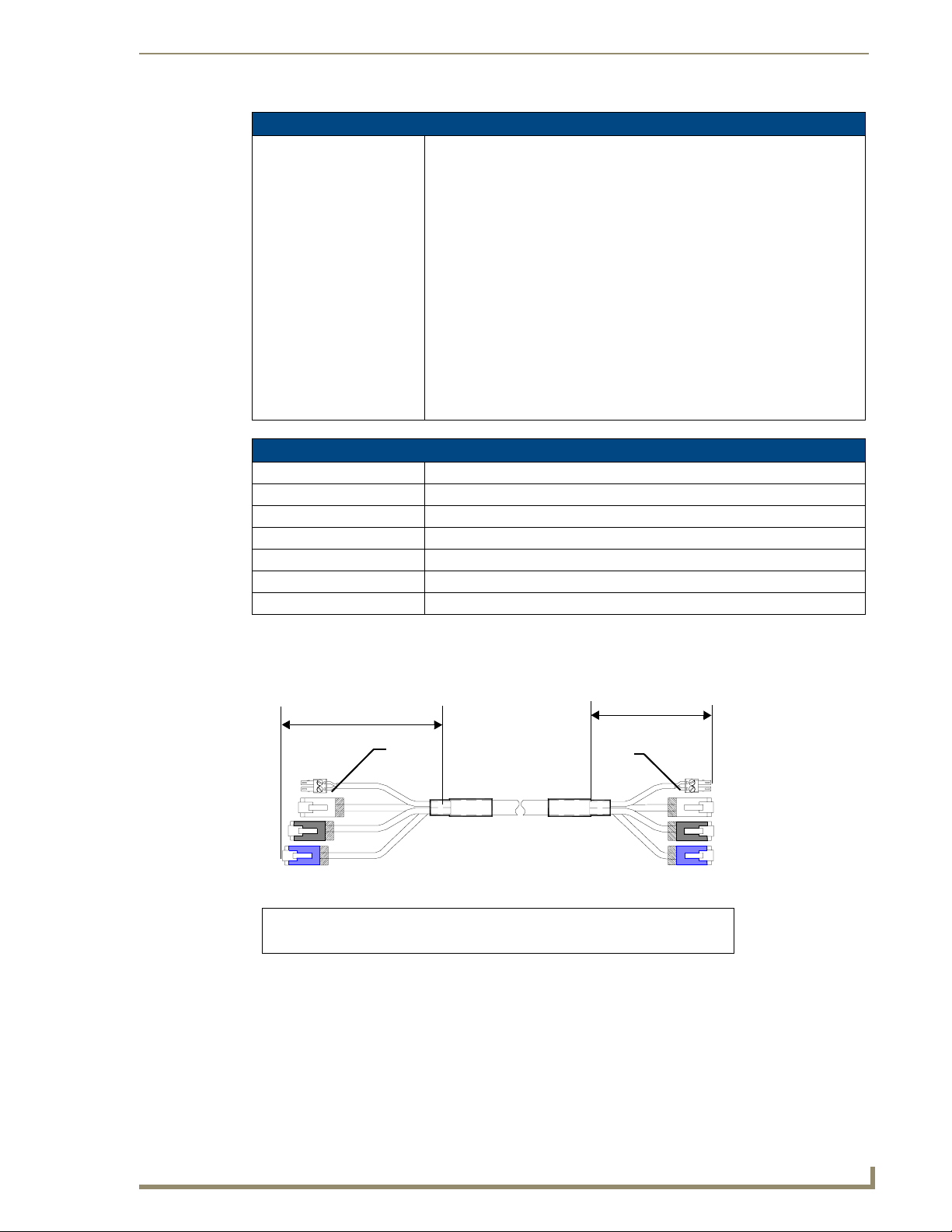
Touch Panel Accessories
NXA-MTC/RGB Specifications (Cont.)
Other AMX Equipment: • Installation Kit for 15" NXD panels (KA2251-02):
- 2-pin mini-Phoenix connector (41-5025)
- Three Phillips-head screws (#4-20 x 0.250 Black) (80-0114-08)
- Two CAT5 Suppression Ferrites (04-0014)
- Four Drywall clips (62-5924-05) and #6 -metal strips (80-0192)
• Installation Kit for 12" NXT panels (KA2251-03):
- 2-pin mini-Phoenix connector (41-5025)
- Three Phillips-head screws (#4-20 x 0.250 Black) (80-0114-08)
- Two CAT5 Suppression Ferrites (04-0014)
• Installation Kit for 15" and 17" NXT panels (KA2251-04):
- 2-pin mini-Phoenix connector (41-5025)
- Three Phillips-head screws (#4-20 x 0.250 Black) (80-0114-08)
- One CAT5 Suppression Ferrites (04-0014)
• Installation Kit for 10" NXT panels (KA2259-01):
- 2-pin 3.5 mm mini-Phoenix connector (41-5025)
- One CAT5 Table Top Suppression Ferrite (04-0014)
- One cylindrical CAT5 USB Mouse Suppression Ferrite (04-0018-SA)
Associated Touch Panels (where used)
FG2251-61RGB NXD-1200VG RGB KIT, 12" MODERO WALLMOUNT RGB KIT
FG2250-61RGB NXT-1200VG RGBKIT, 12" MODERO TABLETOP RGB KIT
FG2253-61RGB NXD-1500VG RGB KIT, 15" MODERO WALLMOUNT RGB KIT
FG2252-61RGB NXT-1500VG RGB KIT, 15" MODERO TABLETOP RGB KIT
FG2256-61RGB NXD-1700VG RGB KIT, 17" MODERO WALLMOUNT RGB KIT
FG2257-61RGB NXT-1700VG RGB KIT, 17" MODERO TABLETOP RGB KIT
FG2255-11 NXA-RGBKIT, RGB UPGRADE KIT FOR EXISTING VG PANELS
Wiring and Connection Information
FIG. 9 shows a top view of the finished cable.
6 inches
Red
3
2
1
4
To Touch Panel
Connector
Connector
FIG. 9
1
- used for Audio/Video (Black)
2
- used for Ethernet (White)
Finished NXA-MTC/RGB Tabletop Cable - showing standard terminations
Connector 3 - used for Power
Connector
3 inches
Red
To Breakout Box
4
- used for RGB (Blue)
3
2
1
4
VG-Series Modero Touch Panels
29
Page 40

Touch Panel Accessories
The following table provides the wiring information for each of the four (4) available connectors on each
side of the NXA-MTC/RGB Tabletop Cable.
Wire Table
Wire Connector 1 Connector 2 Connector 3 Connector 4
1 White/Orange White/Orange Red White/Orange
2 Orange/White Orange/White Black Orange/White
3 White/Green White/Green - White/Green
4 Blue/White Blue/White - Blue/White
5 White/Blue White/Blue - White/Blue
6 Green/White Green/White - Green/White
7 White/Brown White/Brown - White/Brown
8 Brown/White Brown/White - Brown/White
Installing CAT5 Suppression Ferrites
Before connecting the RJ-45 cables to the Modero Touch Panel, install the necessary number of CAT5
Suppression Ferrites (FIG. 10) to the RJ-45 Audio/Video cable. These ferrites come as part of the
Installation Kits mentioned in the previous Specification table (page 28).
No tools are required for this installation.
Release the latch to
open the plastic
enclosure.
FIG. 10
Installing the CAT5 Suppression Ferrites
Insert the CAT5
cable and close
the enclosure.
Push down on the
enclosure until it
snaps closed.
All 1200V-Series, VG-Series, and Table Top CV10 panels require the installation of
an appropriate number of CAT5 Suppression Ferrites when they use an RJ-45 cable
to feed an A/V signal from the breakout box.
1. The CAT5 Suppression Ferrite is housed within a plastic enclosure (shown in FIG. 10) with a latch
release on one side. Pull to release the latch and open the enclosure.
2. Grasp the Black RJ-45 Audio/Video cable being connected to the panel. This end of the cable is
longer than the opposing end which connects to the breakout box (6 inches vs 3 inches).
Refer to FIG. 11 for more detailed information.
3. Insert the panel-end of the Black RJ-45 Audio/Video cable into the groove along the inside of the
enclosure.
The CAT5 Suppression Ferrites MUST be installed onto the cable connected to the
Modero’s Audio/Video RJ-45 connector (just behind the connector).
4. Snap the enclosure shut with the cable inside, and you’re done.
30
VG-Series Modero Touch Panels
Page 41

Touch Panel Accessories
5. Repeat this process again only when installing an additional CAT5 Suppression Ferrite
(model specific).
3
To To uch
Panel
2
1
4
1
Connector
Connector
FIG. 11 Ferrite connector location on Audio/Video RJ-45 cable
- used for Audio/Video (Black)
2
- used for Ethernet (White)
Ferrite
Ferrite
6 inches
Connector 3 - used for Power
Connector 4 - used for RGB (Blue)
It is recommended that any upgrade of internal components be done simultaneously
in order to reduce the risk of damage to internal components.
If a user will be upgrading an NXD panel with a wireless card and an NXA-RGB card
(NXA-RGBKIT), it is recommended that these both be done at the same time if
possible.
NXA-RGB RGB/VGA Interface Card (FG2260)
The NXA-RGB (FIG. 12) is an RGB/VGA plug-in interface card that allows any of AMX’s VG-Series
Modero Touch Panels to accept either RGB or HDTV Component signals directly from an external
source when routed through an optional NXA-AVB/RGB Breakout Box. This card is field upgradeable
and works in-tandem with the RGB connector on the front of an NXA-AVB/RGB Breakout Box.
FIG. 12 NXA-RGB RGB/VGA Interface Card (installed within a VG-Series panel)
The NXA-RGB card is an optional accessory (already installed within Video/RGB panels) that can be
added to any VG-Series Video Modero panel as part of an upgrade kit. The NXA-RGB card is a daughter
card that plugs into the Modero’s main board. This card provides the ability to display computer graphics
(RGB) or component (YCrCb) video within a full screen or resizable on-screen window on the Modero
panel. The NXA-RGB card must be used with the NXA-AVB/RGB Breakout Box. This breakout box
allows the Modero to accept and display high-bandwidth and high-quality RGB as well as HDTV
Component video signals. This box then converts the RGB or component video so that it can be sent
across a UTP (unshielded twisted pair) cable to the from the rear RGB/Component DB-15 connector
(rear of the box), through the front RGB RJ-45 connector, and then to the panel via the RJ-45 connector
on the installed NXA-RGB card.
VG-Series Modero Touch Panels
31
Page 42

Touch Panel Accessories
Product Specifications
NXA-RGB Specifications
Dimensions (HWD): • 0.88" x 3.50" x 6.50" (2.22 cm x 8.89 cm x 16.51 cm)
Weight: • 0.85 lbs (0.39 kg)
Power: • 240 mA @ 12 VDC
Certifications: • FCC Part 15 Class B, CE, and EN 60950
Features: • Accepts RGB or Component inputs (via NXA-AVB/RGB)
Availabili ty : • This component is available separately or as part of NXA-RGBKIT upgrade
Connector: • RJ-45 connector provides RGB/Component video signals (being routed from
Included Accessories: • Five pan-head securing screws
Other AMX Equipment: • Included within the RGB Kit (FGxxxx-xxRGB) is the following:
• Included with 1200VG/1500VG/1700VG RGB Kits
• Integrates output of keyboard and mouse data via RGB port
• On-screen RGB display window is resizable (all the way up to full screen)
• Provides RGB connectivity to the panel over CAT5 cables up to 200 ft.
(60.9 m)
• Receives VGA and Component video signals from the RGB connector on the
front of the NXA-AVB/RGB Breakout Box.
• Routes RGB and computer control pass-thru signals from the USB
connectors on the Modero panel to the RGB connector on the front of the
NXA-AVB/RGB Breakout Box.
kit (FG2255-11) for Modero VG-Series touch panels.
the rear RGB/Component input ports) and touch control information to the
RJ-45 RGB connector on the NXA-RGB card (installed within the panel).
• NXA-AVB/RGB Ethernet/RGB Breakout Box QSG (93-2260)
• This unit is also available within the NXA-RGBKit (FG2255-11):
- NXA-AVB/RGB Breakout Box (FG2254-11)
- NXA-MTC/RGB Combo Table Top cable (CA2250-70)
- NXA-RGB internal RGB/VGA card (FG2260)
- NXA-RGBCBL, 15-pin to 5X BNC RGB Breakout cable (FG2250-80)
- NXT Table Top replacement I/O plate (with RGB connector opening)
(62-2250-59)
- NXD WallMount replacement adhesive overlay for existing I/O plate
(53-2250-03)
- Modero VG Touch Panel (NXD/NXT-1200/1500/1700VG)
- NXA-AVB/RGB Breakout Box (FG2254-11)
- NXA-MTC/RGB Combo Table Top cable (CA2250-70)
- NXA-PCI80211G (FG2255-04) (Table Top Kits ONLY)
- NXA-RGB internal RGB/VGA card (FG2260)
- NXA-RGBCBL, 15-pin to 5X BNC RGB Breakout cable (FG2250-80)
• NXA-AVB/RGB Breakout Box (FG2254-11)
• NXA-MTC/RGB Modero cable (CA2250-70)
• NXA-RGBCBL, 15-pin to 5X BNC RGB Breakout cable (FG2250-80)
32
VG-Series Modero Touch Panels
Page 43

Touch Panel Accessories
Supported Component/VGA Video Resolutions and Formats
NXA-RGB Supported Resolutions and Formats
Resolutions Refresh Rates: Descriptions
VGA Compatible signals:
560 x 192 60 Hz • Apple II
560 x 384 60 Hz • MAC 12”
640 x 350 60 Hz • EGA HP 12”
640 x 416 60 Hz • DOS machines
640 x 480 60 Hz, 72 Hz, 75 Hz, 85 Hz • VGA
720 x 532 60 Hz • IBM 3472
800 x 600 60 Hz, 72 Hz, 75 Hz, 80 Hz •SVGA
900 x 720 60 Hz • Power PC 7 and Power PC 8
1024 x 768 60 Hz, 70 Hz, 75 Hz, 85 Hz •XGA
1280 x 768 60 Hz, 70 Hz, 75 Hz, 85 Hz •WXGA
1280 x 800 60 Hz, 70 Hz, 75 Hz, 85 Hz •WXGA
1152 x 864 60 Hz, 70 Hz, 75 Hz •XGA
1280 x 1024 60 Hz, 75 Hz, 85 Hz •SXGA
1600 x 1200 60 Hz •UXGA
Component/HDTV
Compatible signals:
720 x 483 • HD 480p - SMPTE 293M
1280 x 720 • HD 720p - SMPTE 296M
1920 x 1080 • HD 1080i - SMPTE 27 4M
RGB RJ-45 connection and wiring information
This RJ-45 connector is used to route the signals connected to the RGB / Component input port on the
rear of the AVB/RGB Breakout Box to the VG-Series Modero panel. Standard CAT5 cable can be used
for this connection with short cable runs under 50 feet (15.24 m). For cable runs over 50 feet (15.24 m),
AMX recommends using the Belden Brilliance VideoTwist 7987. This Belden cable is not CAT5
compliant, but is designed to control skew between the red, green, and blue video signals. Therefore, for
longer cable runs, the video quality will be much higher using the Belden VideoTwist 7987 cable versus
standard CAT5 (or other Ethernet compliant cables). The pinout of this RGB connector is given in the
table below.
The Belden cable only adjusts for RGB skew but may still need to be configured
properly for cable length by using the Cable Variance setting on the RGB Adjustment
page (Video Adjustment - RGB Adjustment Page section on page 142).
VG-Series Modero Touch Panels
33
Page 44

Touch Panel Accessories
RGB RJ-45 Connector Pinouts and Signals
Pin Color Function Polarity
1 Orange-White Blue Video -
2 Orange Blue Video +
3 Green-White Data
4 Blue Green Video -
5 Blue-White Green Video +
6 Green Data
7 Brown-White Red Video -
8 Brown Red Video +
It is important that the correct pairing is observed.
NXA-CFTP Compact Flash (FG2116-22)
Every Modero panel is shipped with two factory default modules: an EXM Memory Module and a
Compact Flash card. These panels are shipped with a 256 memory module which is not
upgradeable. The default 128 MB Compact Flash card is factory programmed with specific panel
firmware and is the only upgradeable memory component. This component can be ordered from AMX in
several different upgrade sizes (as listed in the following table):
(bidirectional)
(bidirectional)
-
+
TIA 568B
Optional Compact Flash Memory Upgrades
Compact Flash:
NXA-CFTP256M - 256 MB Compact Flash card (FG2116-23)
NXA-CFTP512M - 512 MB Compact Flash card (FG2116-24)
NXA-CFTP1G - 1 GB Compact Flash card (FG2116-25)
Upgrading the internal components involves opening the panel enclosure/outer housing to access the
internal circuit board, removing the existing part, and replacing them with the upgrade components, as
described in the following sections.
It is recommended that any upgrade of internal equipment be done simultaneously in
order to reduce the risk of damage to internal components.
t
34
VG-Series Modero Touch Panels
Page 45

Touch Panel Accessories
NXA-PCI80211G Wireless Card (FG2255-04)
The 1200V-Series and VG-Series Modero touch panels can connect to an internal NXA-PCI80211G
mini-PCI Wireless Card (FIG. 13) connected to two antennas (57-2250-10).
FIG. 13 NXA-PCI80211G mini-PCI Wireless Card
The NXA-PCI80211G card functions using a 2.4GHz bandwidth with a maximum data transfer rate of
54Mbps. This card is compatible with IEEE 802.11 standards such as: 802.11b and 802.11g.
The NXA-80211G allows the end-user to take advantage of larger bandwidth to utilize features such as:
streaming digital video and audio, wireless intercom, Motion JPEG, networked video, and standard
wireless Ethernet communication to both a NetLinx controller and networked computers.
Please follow your particular Wireless Access Point’s instruction manual for the correct procedures to
setup either a secured or unsecured connection.
FCC Statement:
This device complies with Part 15 of the FCC rules. Subject to the following two conditions:
1. This device must not cause harmful interference and
2. This device must accept all interference, including interference that interferes with the
operation of this device.
Modifications not expressly approved by the manufacturer will void the user’s authority
to operate the equipment.
WARNING: This device has been evaluated and found to be compliant with the FCC Rules
for RF Exposure when the device is operated at a minimum separation distance from the
user and nearby persons. Operation of this device at closer distances should be avoided.
Certifications
FIG. 14 FCC Statement
Product Specifications
NXA-PCI80211G Specifications
Dimensions (HWD): • 0.02" x 2.13" x 4.66" (5.0 mm x 54.0 mm x 118.4 mm)
Description: • Direct Sequence Spread Spectrum (DSSS)/CCK 802.11g Wireless mini-PCI
Weight: • 1.05 oz (30g)
Antenna Type: • Dual antenna connector
Bus Interface: • mini-PCI card, TypeIII B
Certifications: • FCCID: CWU-WN2301A, CE, EN 60950, EN 300 328, and RSS 210and
: FCCID: CWU-WN2301A, CE, EN 60950, EN 300 328,
and RSS 210
card with detachable antennas.
FCCID (CWU-WN2301A)
VG-Series Modero Touch Panels
35
Page 46

Touch Panel Accessories
NXA-PCI80211G Specifications (Cont.)
Features: • Contains integrated power amplifier (PA) and low-noise amplifier (LNA)
Frequency Range: • Using 802.11b & g communication:
Media Access Technique: • CSMA/CA with ACK
Modulation: • Orthogonal Frequency Division Multiplexing (OFDM) / Complementary Code
Network Architecture: • Ad-hoc mode (Peer-to-Peer)
Network Standard: • IEEE Compliant
Operating Channels: • Using 802.11b & g communication:
Operating Environment: • Temperature: 0°C ~ 55°C (32°F to 131°F) (operating) and
Operating Voltage: •3.3V +
Power Consumption: • @ 802.11b communication:
Radio Data Rate: • 802.11g compliant: 1, 2, 5.5, 11 (DSSS/CCK); 6, 9, 12, 18, 24, 36, 48, and 54
Receiver Sensitivity: • Using 802.11b communication:
• Diversity Antenna Connectors automatically select the best available signal
• Enhanced transmit and receive chains
• Field-installable
• Increased sensitivity and multipath tolerance
• Operates from 2.300-2.500 GHz
• Operate at ISM frequency bands (2.4GHz) with 54Mbps data rate
• Pre-configured to communicate with current AMX Wireless Access Points
• Support for IEEE 802.11b and 802.11g
• Wired Equivalent Privacy (WEP) 64-bit and 128-bit data encryption
- 2.412 ~ 2.462 GHz - North America
- 2.412 ~ 2.484 GHz - Japan
- 2.412 ~ 2.472 GHz - Europe ETSI
- 2.457 ~ 2.462 GHz - Spain
- 2.457 ~ 2.472 GHz - France
Keying (CCK)
• Infrastructure mode
• 802.11b and 802.11g
- 11: (Ch 1 - 11) - North America
- 14: (Ch 1 - 14) - Japan
- 13: (Ch 1 - 13) - Europe ETSI
- 2: (Ch 10 - 11) - Spain
- 4: (Ch 10 - 13) - France
-20°C ~ 70°C (-4°F to 158°F) (storage)
• Humidity: (non-condensing) 5% ~ 90% RH (operating) and
(non-condensing) 5% ~ 95% RH (storage)
5% I/O supply voltage
- RX: 300 mA
- TX: 64 mA
- Sleep: 12mA
• @ 802.11g communication:
- RX: 330 mA
- TX: 575 mA
- Sleep: 12mA
(OFDM) Mbps data rates
1 Mbps: -86 dBm (max)
2 Mbps: -84 dBm (max)
5.5 Mbps: -83 dBm (max)
11 Mbps: -80 dBm (max)
• Using 802.11g communication:
1 Mbps: -86 dBm (max)
2 Mbps: -84 dBm (max)
5.5 Mbps: -83 dBm (max)
11 Mbps: -80 dBm (max)
36
VG-Series Modero Touch Panels
Page 47

Touch Panel Accessories
NXA-PCI80211G Specifications (Cont.)
Security: • 64-bit and 128-bit WEP
Availabili ty : • All 1200V-Series and VG-Series NXT Table Top panels can be field upgraded
for wireless communication using the optional NXA-PCI80211G mini-PCI
card.
• Optional to the following NXD panels:
- NXD-1200V
- NXD-1200VG
- NXD-1500VG
- NXD-1700VG
Installation and Upgrade of the Internal NXT Components
Upgrading the components within each of the Table Top panels involves removing the outer housing
(with speaker plate), removing and/or installing an existing component, and then placing the outer
housing back onto the NXT panel, as described in the following sections.
Do not use Ethernet cables containing mounting boots. These boots could make
removal of the Ethernet connectors (from the panel) difficult and cumbersome.
Step 1: Remove the existing NXT Outer Housing
Carefully detach all connectors from the rear of the touch panel and then gently place the touch
1.
panel LCD facedown onto a soft cloth to expose the under-side of the base (FIG. 15). This step
helps prevent scratching of the LCD.
2. Tilt the base forward so that both the bottom surface and Housing Screws are easily accessible and
then carefully remove the four plastic adhesive feet.
Reference the location of the four plastic adhesive "feet". Once the outer housing is
placed back onto the panel, these "feet" must be placed back in their original
locations so they can fit into their provided openings on a Battery Base.
3. While holding the outer housing and base plate at a 45° (to prevent it from sliding), use a grounded
Phillips-head screwdriver to remove the eight Housing Screws.
Base plate
Unscrew these
eight Housing
Screws to remove
the circuit board
housing
DO NOT
REMOVE
these screws
They secure
the speakers
to the main
board
Outer housing
45°
Hinge Brackets (2)
FIG. 15 Location of the attachment screws on an NXT panel
4. Rotate the panel back over (while gripping the entire unit with outer housing) and rest the base back
on a flat surface.
5. Gently tilt the LCD backward to a 45° angle.
VG-Series Modero Touch Panels
37
Page 48

Touch Panel Accessories
6. In a single motion, carefully pull the outer housing up and then out (away from the LCD panel) to
7. Unscrew the Stereo Output nut from the Stereo Output jack.
8. Firmly grab the existing connector plate and slide it up and away from the base. This part is later
Step 2: Install the 802.11g mini-PCI Wireless Card
1.
2. Locate the mini-PCI card connector on the main board (FIG. 16 and FIG. 17).
expose the internal circuit board (FIG. 19). The NXA-RGB card is available within both the
optional RGB Kit and NXA-RGBKIT upgrade.
replaced with the RGB connector plate.
Discharge any static electricity from your body by touching a grounded metal object.
Outer Housing
NXA-PCI80211G
wireless card
location
I/O connector
Eight Housing
Screws
FIG. 16 Location of the NXA-PCI80211G wireless card on the NXT board
FIG. 17 Location of the mini-PCI card connector on main board
plate
Compact Flash card
If you have previously installed an NXA-RGB card, it must first be removed prior to
gaining access to the mini-PCI connector on the board.
38
3. Carefully remove the gold-tipped terminal ends of the antenna from their factory default connectors
on the main board. The antenna is secured at this location to restrict its movement prior to
connection to a wireless card.
4. Firmly grasp the NXA-PCI80211G mini-PCI card (from the edges) and insert the pins (at a 25°
angle) into the opening on the connector (FIG. 18).
VG-Series Modero Touch Panels
Page 49

Touch Panel Accessories
5. While maintaining the 25° angle alignment on the new module, push it in firmly until the contact
pins are completely inside the connector and the card "snaps" into place (FIG. 18).
6. Push the card downward (to the main board) until the side braces snap atop the NXA-PCI80211G
and hold it in place.
Antennas connectors
Connection point
between the braces and
the mini-PCI card
FIG. 18 Installation of the mini-PCI card connector on main board
7. Locate the terminal ends of the antennas and apply downward pressure to "snap" them onto their
gold-tipped counterparts on the mini-PCI card (FIG. 18). Carefully push down on each connector to
verify it is securely joined to the card.
It is recommended that any upgrade of internal equipment be done simultaneously in
order to reduce the risk of damage to internal components.
If you are also installing an NXA-RGB card (as part of an NXA-RGBKIT), refer to the
installation procedures on page 22 before replacing the outer housing.
Step 3: Install the NXA-RGB Card Component (NXT)
Discharge any static electricity from your body by touching a grounded metal object.
1.
2. Locate the RGB card’s slot connector on the main board and align it with its counterpart on the
bottom of the NXA-RGB card.
3. Carefully, but firmly, insert the NXA-RGB card into the RGB connector slot on the main board until
both the card rests atop the four raised securing holes and the RGB RJ-45 connector is evenly
aligned with the other RJ-45 connectors on the back of the panel.
4. Use a grounded Phillips-head screwdriver to secure the four NXA-RGB pan-head securing screws
to the raised securing holes on the main board.
5. To complete the upgrade process, either upgrade the remaining component (Step 3) or close and
re-secure the enclosure using the procedures in Step 5: Close and Resecure the NXT Panel
Enclosure section on page 41.
VG-Series Modero Touch Panels
39
Page 50

Touch Panel Accessories
FIG. 19 Location of the NXA-RGB card and I/O plate
Step 4: Install the Compact Flash Memory Card upgrade
Outer Housing
NXA-RGB card
NXA-RGB card
screw locations (4)
RGB I/O
connector plate
Discharge any static electricity from your body by touching a grounded metal object and then locate
1.
the existing Compact Flash card (factory-shipped with 128 MB) on the main board (FIG. 20 for
Table Top panels and FIG. 23 for Wall Mount panels).
Outer Housing
NXA-PCI80211G
wireless card
location
I/O connector
Eight Housing
Screws
plate
Compact Flash card
40
FIG. 20 Location of the Compact Flash card and I/O plate on NXT
2. Insert the tip of a grounded flathead screwdriver into one of the card removal grooves (located on
either side of the card), and gently pry the card out of the slot (FIG. 21). Repeat this process on the
opposite card removal groove. This alternating action causes the card to "wiggle" away from the
on-board connector pins.
3. Grip the old card by its sides and then carefully pull it out of the slot.
VG-Series Modero Touch Panels
Page 51

Touch Panel Accessories
Card removal
grooves
On-board Compact
Flash connector (with pins)
Insert with arrow
facing towards the pins
Connector opening
FIG. 21 Removing/installing a Compact Flash Memory card
4. Remove the new CF memory card from it’s anti-static bag.
5. Grip the sides of the new CF memory card and firmly insert it into the slot opening (with the arrow
facing towards the pins) until the contact pins are completely inside the flash card and it is then
securely attached to the pin sockets.
6. To complete the upgrade process, close and resecure the panel enclosure using the procedures in the
following step.
Any new internal component upgrade is detected by the panel only after power is
cycled.
Step 5: Close and Resecure the NXT Panel Enclosure
Obtain the new RGB I/O connector plate (similar to the original but containing the added RGB
1.
connector opening to the newly installed NXA-RGB) and slide it back into position.
2. Resecure the Stereo Output nut back onto the new Stereo Output jack onto the new RGB I/O plate.
3. With the components securely installed, tilt the LCD back to a 45° and then gently slide-on the outer
housing (towards the LCD) until the it is aligned over the installation holes and the tilt bracket
prevents any further forward movement (FIG. 19).
4. Gently press down on the housing (toward the base) until it is securely positioned over the circuit
board and cover base.
Use caution when re-installing the outer housing. Improper re-installation can cause
damage to the internal speakers.
5. While holding the circuit board cover in place, turn the panel back over until the LCD lies facedown
on a soft cloth and the under-side of the base is exposed.
6. Insert and secure the eight Housing Screws (using a grounded Phillips-head screwdriver) into their
respective locations (FIG. 15).
7. Replace any adhesive plastic "feet" that might have been removed during the removal process of the
outer housing. These "feet" must be placed back onto their original locations so they can fit into
their provided openings on the Battery Base.
VG-Series Modero Touch Panels
41
Page 52

Touch Panel Accessories
8. Grasp both the LCD and housing and then rotate the entire unit back onto a flat surface.
9. Insert all connectors and apply power.
Installation and Upgrade of the Internal NXD Components
Upgrading the components within a WallMount panel involves removing the rear plastic outer housing
(back box), removing and/or installing an existing component, and then placing the back box back onto
the NXD panel, as described in the following sections.
Step 1: Remove the existing NXD Outer Housing
1.
2. Place the LCD facedown onto a soft cloth to expose the under-side of the unit. This step helps
3. Unscrew the Stereo Output nut from the Stereo Output jack.
4. Remove the I/O connector plate by using a grounded Phillips-head screwdriver to remove the two
Carefully detach all connectors from the side of the touch panel and remove the front magnetic
faceplate from the NXD unit by firmly gripping the faceplate and pulling outwards, while applying
a small amount of pressure to remove it from the main unit.
prevent scratching of the LCD.
screws and slide the I/O connector plate away from the back box housing.
DO NOT REMOVE THE PANEL SECURING SCREWS. These screws secure the
LCD to the metallic casing.
5. Unscrew the four pan-head Housing Screws from the rear of the NXD unit (FIG. 22) and gently
remove the outer housing. These four screws secure the back box to the internal panel casing.
DO NOT
REMOVE
these
panel
securing
screws
Unscrew these four Housing Screws
to remove the back box.
These make direct contact with the black
outer housing.
FIG. 22 Location of the securing screws on an NXD panel
DO NOT REMOVE
these panel
securing screws
42
VG-Series Modero Touch Panels
Page 53
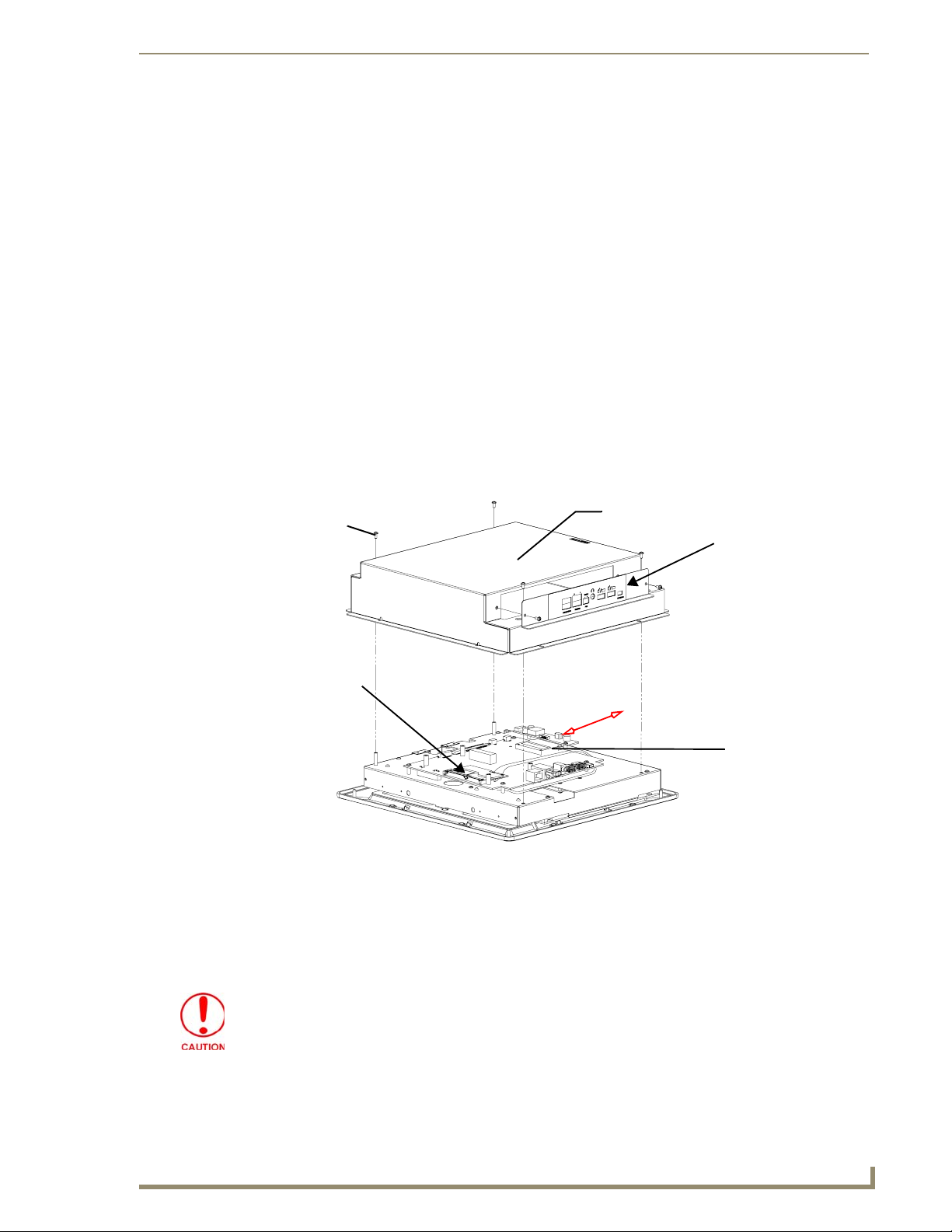
Touch Panel Accessories
Step 2: Install the new 802.11g mini-PCI Wireless card (NXD)
Complete the procedures outlined within Step 2: Install the 802.11g mini-PCI Wireless Card section on
page 38 and then continue with the following step.
Step 3: Install the new RGB Card Component (NXD)
Discharge any static electricity from your body by touching a grounded metal object.
1.
2. Locate the RGB card’s slot connector on the main board and align it with its counterpart on the
bottom of the NXA-RGB card.
3. Carefully, but firmly, insert the NXA-RGB card into the RGB connector slot on the main board until
both the card rests atop the four raised securing holes and the RGB RJ-45 connector is evenly
aligned with the other RJ-45 connectors on the back of the panel.
4. Use a grounded Phillips-head screwdriver to secure the four NXA-RGB pan-head securing screws
to the raised securing holes on the main board. Refer to the Step 3: Install the NXA-RGB Card
Component (NXT) section on page 39 for more information.
Step 4: Install the new Compact Flash Memory card (NXD)
1.
Complete the procedures outline within Step 4: Install the Compact Flash Memory Card
upgrade section on page 40 and then continue with the following step.
Four Pan-head
Housing
Screws
NXA-PCI80211G
wireless card
location
FIG. 23 Location of the Compact Flash card and I/O plate on NXD
Outer Housing
I/O connector
plate
Compact Flash card
Step 5: Close and Resecure the NXD Panel Enclosure
With the components securely installed, gently place the outer housing back onto the metallic panel
1.
casing (with the connector opening on the right-side of the panel) and align the four pan-head
Housing Screw holes along the edges of the outer housing.
Use care not to bend or damage any antenna connections while replacing the outer
housing.
2. Insert and secure the four pan-head Housing Screws into the pre-drilled holes along the edges of the
NXD unit by using a grounded Phillips-head screwdriver.
VG-Series Modero Touch Panels
43
Page 54

Touch Panel Accessories
3. Remove the previous I/O plate adhesive overlay (this reveals a pre-drilled RGB connector opening)
4. Reinstall the upgraded RGB I/O connector plate by aligning all connectors to their respective
FIG. 24 NXD I/O plate with upgraded RGB overlay
5. Secure the I/O plate using a grounded Phillips-head screwdriver and then twist the Stereo Output
NXT-BP Power Pack (FG2255-10)
The NXT-BP Power Pack (FIG. 25) is a rechargeable Lithium-Ion "smart" battery used to provide power
to the NXT Modero panel through the NXA-BASE/B Battery Base. This battery incorporates an onboard battery life indicator. The NXT-BP battery can be charged through either the base (when
connected to the Modero panel) or through an optional NXT-CHG Modero Power Station. Extra NXTBP Power Packs can be purchased separately as an optional accessory.
and replace it with the new adhesive RGB overlay (53-2250-03).
locations (FIG. 24).
nut back onto the Stereo Output jack.
44
FIG. 25 NXT-BP Power Pack
Product Specifications
NXT-BP Specifications
Dimensions (HWD): • 0.69" x 3.50" x 5.81" (1.75 cm x 8.89 cm x 14.76 cm)
Power (Voltage): • 11.1 Volts (nominal)
Weight: • Single NXT-BP Power Pack: 1.0 lbs (0.45 kg)
Features: • Battery Usage: 3 to 8 hours (time is panel-type and usage dependant)
• Charge Capacity: 6300mAh
Operating / Storage
Environment:
• Operating Temperature: 0° C (32° F) to 40° C (104° F)
• Operating Humidity: 20% - 85% RH
• Storage/Discharge Temperature: -20° C (-4° F) to 60° C (140° F)
• Storage Humidity: 5% - 85% RH
VG-Series Modero Touch Panels
Page 55

Touch Panel Accessories
NXA-BASE/B Battery Base Kit (FG2255K)
The NXA-BASE/B Battery Base is a Modero accessory that allows the Modero Table Top touch panels
(NXT) to function off the collective charge of two internally connected NXT-BP batteries (FG2255-10).
The base provides both power and battery information to the panel via the panel interface connector
(FIG. 26). The NXT-BP batteries can be charged through either the base (only when connected to the
NXT touch panel) or through an optional NXT-CHG Modero Power Station.
Panel Interface
Connector
NXA-BASE/B
Battery Base
FIG. 26 NXA-BASE/B and NXT-BP combo
NXT-BP
Battery Pack
This base also comes as part of a NXA-BASE/B Kit that contains one (1) battery base and two batteries.
The accompanying batteries can be charged through either the base or optional NXT-CHG Battery
Charger (FG2250-50). Refer to the Installing the NXA-BASE/B to an NXT Modero Panel section on
page 46 for more detailed installation and usage instructions.
Product Specifications
NXA-BASE/B Specifications
Dimensions (HWD): • 1.13" x 8.63" x 11.81" (2.86 cm x 21.91 cm x 30.00 cm)
Power Requirements: • 2.7 A @ 12 VDC (max power draw while charging)
Weight: • Base unit: 1.25 lbs (0.567 kg)
• Base and 2 batteries: 3.23 lbs (1.47 kg)
Features: • Charge time for two depleted batteries ~ 5 - 8 hours (when NXT panel is in
Operating / Storage
Environment:
Other AMX Equipment: • NXT-CHG Kit (FG2250-50K):
Sleep mode)
• Must be connected to the Modero unit utilizing a 12 VDC-compliant power
supply
• Operating Temperature: 0° C (32° F) to 40° C (104° F)
• Operating Humidity: 20% - 85% RH
• Storage Temperature: -20° C (-4° F) to 60° C (140° F)
• Storage Humidity: 5% - 85% RH
1 charger (FG2250-50) and 2 NXT-BP batteries (FG2255-10)
• NXT-BP battery pack (FG2255-10)
• NXT-CHG battery charger (FG2250-50)
It is recommended to fully charge the batteries before their initial use.
VG-Series Modero Touch Panels
45
Page 56

Touch Panel Accessories
Checking the NXT-BP battery charge
1.
FIG. 27 NXT-BP (showing Battery Life Indicator button and charge)
2. Repeat the above step for each NXT-BP battery.
3. Charge the NXT-BP battery by either inserting it into the battery base or from within the optional
If the 25% LED is blinking, this indicates there is less than 5% of a charge remaining
on the battery.
Press the Battery Life Indicator button (FIG. 27) once to illuminate the Battery Life LEDs and
display the percent charge remaining on the battery (this indication lasts a few seconds).
Battery Life (Charge) Display
Battery Life Indicator button
NXT-CHG charger (which can sequentially charge up to two batteries).
Installing the NXA-BASE/B to an NXT Modero Panel
The battery base must be installed onto the NXT panel without any NXT-BP batteries.
1. Power Off the panel before attempting to use the NXA-BASE/B.
2. Place the empty battery base onto a flat/level surface.
3. Verify the alignment of the Panel Interface connectors between the panel (male connector) and base
(female connector) (FIG. 28).
Battery Compartment
pulls outwards
Alignment
pegs
FIG. 28 NXA-BASE/B showing Panel Interface and connector locations
Captive fasteners
(secure base to
panel)
Panel Interface
connector (female)
46
4. Carefully place the Modero panel over the base alignment pegs (FIG. 28 and FIG. 29).
VG-Series Modero Touch Panels
Page 57

Touch Panel Accessories
The battery base cannot be "hot-swapped". A panel receiving power through a
connected 12 VDC-compliant power supply cannot have a battery base installed onto
the bottom of the panel while powered. POWER OFF the panel before installing the
NXA-BASE/B.
"Hot swapping" could damage the base and cause it not to be recognized by the
panel.
5. Gently apply downward pressure until the panel is securely mounted to the battery base (FIG. 29).
Top view
Alignment
pegs
FIG. 29 NXA-BASE/B shown aligning with NXT panel
Panel Interface
connector
(female)
Bottom view
Interface
connector
(male)
Captive
fasteners
6. Firmly grip both the panel (from the side) and battery base (from below) together.
7. Gently place the touch panel LCD facedown onto a soft cloth (this prevents scratching of the LCD
while the battery base is being secured).
8. Locate the captive fasteners on the underside of the battery base by angling the base combo slightly
forwards.
9. Secure each captive fastener head using a grounded flat-head screwdriver until the NXA-BASE/B is
securely attached to the underside of the NXT Modero touch panel.
10. Firmly grip the panel LCD/base combo and gently rotate the unit back onto the base.
Installing an NXT-BP into the NXA-BASE/B
The battery base does not directly connect to a power supply, but rather receives its power directly from
the Modero panel, through the Panel Interface connector.
Remove any connectors from the rear of the Modero NXT panel before continuing
with the installation of the batteries. Power can only be supplied after the batteries
have been installed.
1. With the panel mounted on the battery base, open the battery compartment (FIG. 30) by pulling the
handle outwards. This compartment houses two NXT-BP batteries.
2. Install the NXT-BP battery. label-side down.
VG-Series Modero Touch Panels
47
Page 58

Touch Panel Accessories
NXT-BP Battery #2
Battery
Connectors
Interface
connector
Battery
Connector
Por t
Battery #2
slot
Battery
Compartment
FIG. 30 Battery installation procedure
FRONT
NXT-BP Battery #1
3. Align the battery connectors with the corresponding battery connector port (located inside the
battery compartment), as shown in FIG. 30.
4. Insert the NXT-BP battery until the connectors securely fit into the battery connector port.
5. Repeat steps 2 through 4 for the other battery.
6. Apply a small amount of pressure to close the battery compartment until the compartment latches.
After a few seconds, the panel will turn On and the AMX logo will appear (indicating the
panel is receiving power.
Charging the NXT-BP batteries with the NXA-BASE/B
Follow the procedures from the previous sub-section to attach the NXT touch panel to the
1.
NXA-BASE/B.
2. Insert each battery into the battery compartment shown in FIG. 30.
3. Insert a 2-pin connector from a power supply to the rear PWR connector on the NXT Modero panel.
The charge status bargraph indicators, on the Battery Base page, indicate when the batteries
are fully charged.
48
The NXA-BASE/B will only charge batteries when the NXT panel is in Sleep mode.
VG-Series Modero Touch Panels
Page 59

Touch Panel Accessories
NXT-CHG Battery Charger Kit (FG2255-50K)
The NXT-CHG Kit includes one charger and two batteries. The optional NXT-CHG Modero Power
Station (FIG. 31) is a two-slot, stand-alone battery charger that can be used to recharge up to two
NXT-BP batteries. The batteries are charged in the order they are inserted into the charger. The
NXT-CHG Slot 1 has the feature of being able to completely discharge and recharge (recalibrate) a
battery.
Battery Life indicator
NXT-BP Modero Power Pack (battery)
NXT-CHG Modero Power Station (charger)
FIG. 31 NXT-CHG Kit (consists of one NXT-CHG charger and two NXT-BP batteries)
Product Specifications
NXT-BP and NXT-CHG Specifications
Dimensions (HWD): • 1.13" x 8.63" x 11.81" (2.86 cm x 21.91 cm x 30.00 cm)
Power Requirements: • NXT-BP Battery Voltage - 11.1 Volts
• NXT-CHG: 90 - 264 VAC, 47-63 Hz, Single Phase
(using the included 24 VDC power supply)
Weight: • 0.57 lbs (0.26 kg)
Features: • Charge time for two depleted batteries: ~ 5 hours
• Charge Rate: 2.5 A @ 12 VDC
• 2-Bays: Sequential charging
• LED: One LED indicator in front of each bay which conveys the status of that
bay. Refer to the Reading NXT-CHG LED Indicator section for more
information.
• Recalibration pushbutton (located between the bays): Initiates recalibration
sequence in the left bay only.
• Recalibration Time: less than 9 hours
Other AMX Equipment: • NXT-BP battery pack (FG2255-10) (additional)
The batteries are charged in the order they are inserted into the NXT-CHG. SLOT 1 of the NXT-CHG
has the ability to completely discharge and recharge (recalibrate) a battery.
Recalibration improves the reporting accuracy of the battery charge back to the
Modero panel.
VG-Series Modero Touch Panels
49
Page 60

Touch Panel Accessories
Powering the NXT-CHG
The NXT-CHG Smart Battery Charger uses an included power supply to charge inserted batteries.
1. Connect the rear of the NXT-CHG to the power adapter.
2. Connect the power adapter to the provided power cord (with plug).
3. Provide power to the unit by connecting the power cord (with plug) into a power outlet that meets
Reading NXT-CHG LED Indicator
FIG. 32 shows the components on the NXT-CHG Smart Battery Charger.
(recalibration)
Slot 1
the requirements outlined in the Specifications section for the NXT-CHG.
Slot 1
Slot 2
LED
Slot 2
LED
Recalibrate
Pushbutton
FIG. 32 Component locations on the NXT-CHG
There is one LED indicator on the front of each battery slot that indicates the status of that slot. The blink
patterns for these LEDs are described in the following table:
• Off: No battery detected.
• Green Flashing: Fast charging.
• Green Solid: Fully charged.
• Yellow Flashing: Recalibration in process.
• Yellow/Green: Recalibration complete.
• Yellow Solid: Standby (waiting for other battery to charge).
• Red Flash: Error (problem with either the battery connection to the internal slot, or with
the battery itself).
Charging the NXT-BP batteries using the NXT-CHG
Review the Checking the NXT-BP battery charge section on page 46 to confirm the percentage of
1.
charge remaining on the batteries.
2. Provide power to the charger (as outlined in the Powering the NXT-CHG section on page 50).
3. Align the battery connector with the corresponding charge slot within each of the two NXT-CHG
slots.
4. Firmly insert the battery into the desired slot until the battery is both securely located within the slot
and there is activity from the corresponding Slot LED. Refer to the Reading NXT-CHG LED
Indicator section on page 50 section for LED information.
50
VG-Series Modero Touch Panels
Page 61

Touch Panel Accessories
Recalibrating the batteries
The recalibration process increases the accuracy of the battery charge level. Recalibration of the batteries
is only done upon request from the Modero on-screen Battery Base page. Refer to the Battery Base
Page section on page 151 for more detailed Battery Base page information.
Recalibration can only be done with Slot 1 on the NXT-CHG.
1. Place the selected battery securely into Slot 1 (left slot) until there is activity on the Slot 1 LED.
2. Push the Recalibration pushbutton (located between the two slots) to initiate recalibration in the
left bay only.
VG-Series Modero Touch Panels
51
Page 62

Touch Panel Accessories
52
VG-Series Modero Touch Panels
Page 63

Installation Procedures: 12" and 15" Panels
Installation Procedures: 12" and 15" Panels
Overview
NXT panels are mounted onto flat (horizontal) surfaces in either a stand-alone or combo (NXT atop an
NXA-BASE/B battery base) configuration. NXD panels are installed into either a pre-wall surface (using
a CB-TP12/CB-TP15 conduit/wallbox) or a solid surface (using either solid surface or drywall screws).
It is recommended that if you are planning on upgrading your panel components
(flash, wireless, RGB card), you do so before beginning any panel installations.
Unpacking the Panel
1. Inspect and confirm the contents of the shipment box to verify that you have all specified parts.
Refer to the Specifications sections on page 2 and page 7 for more information about included
accessories and other AMX equipment.
2. Carefully remove the panel from the shipping box.
3. Carefully peel the protective plastic cover from the LCD.
If the protective plastic LCD cover is not removed, the panel may not respond
properly to touch points on the LCD or allow proper screen calibration.
Installing Internal Components
Installation of the internal components such as the NXA-PCI80211G Wireless card and NXA-RGB
Interface card are described in detail within the following sections:
Step 2: Install the 802.11g mini-PCI Wireless Card section on page 38.
Step 3: Install the NXA-RGB Card Component (NXT) section on page 39.
Upgrading to the MB-TP12/MB-TP15 VESA Mounting Kit
Upgrading the existing back box with the new VESA Mounting Kit on both the 12" (FG031-50) and
15" panel (FG032-50) is identical and requires 3 main processes:
Removing the pre-existing back box and installing the new VESA back box.
Threading cables through the strain relief grommet opening in the rear plastic cover.
Finalizing the installation of the NXD (with VESA back box and cables) into the plastic cover,
securing both components, and finalizing the strain relief grommet installation.
The installation procedures found in this section are identical for both sizes of panels
(12" and 15"). Only overall dimensions and FG product numbers are different.
The new MB-TP Universal VESA Mounting Box uses a standard VESA installation
pattern of 75 mm between holes. VESA mounts that conform to this pattern can be
used on the MB-TP Housing.
VG-Series Modero Touch Panels
53
Page 64

Installation Procedures: 12" and 15" Panels
Removing the Original Modero Back Box
1.
Detach all connectors from the side of the touch panel.
2. Remove the magnetic faceplate from the NXD unit by gripping the faceplate and pulling outwards
while applying a small amount of pressure to remove it from the main unit.
3. Place the LCD face-down on a soft cloth to expose the back of the panel and prevent scratching of
the LCD.
4. Unscrew the Stereo Output nut from the Stereo Output jack.
5. Remove the I/O connector plate by using a grounded Phillips-head screwdriver to remove the two
screws and slide the I/O connector plate away from the back box housing.
6. Remove the four pan-head Housing Screws from the rear of the NXD unit (FIG. 33). These screws
secure the back box to the internal panel casing.
DO NOT
REMOVE
these
panel
securing
screws
DO NOT REMOVE
these panel
securing screws
Unscrew these four Housing Screws
to remove the back box.
These make direct contact with the black
outer housing.
FIG. 33 Location of the attachment screws on the NXD back box
DO NOT REMOVE THE FOUR PANEL SECURING SCREWS. These screws secure
the LCD to the metallic casing underneath.
7. Lift the back box housing to separate it from the internal panel casing.
Installing the MP-TP12/15 Back Box
Unscrew the four pan-head Housing screws (#8-32) from the MP-TP12/15 rear plastic cover.
1.
2. Gently place the MP-TP12/15 back box over the internal panel casing (with the cable routing hole
on the right-side of the panel).
3. Re-install and secure the four pan-head Housing Screws into their pre-drilled holes along the edges
of the MB-TP12/15 back box (FIG. 34) and secure them using a grounded Phillips-head
screwdriver.
4. Place the I/O connector plate back over the connector opening and align the connector locations.
5. Resecure the I/O connector plate (using a grounded Phillips-head screwdriver) and resecure the
Stereo Output nut on the Stereo Output jack.
54
VG-Series Modero Touch Panels
Page 65

Tw e l ve
#6-32
securing
screws
Internal panel casing
DO NOT REMOVE
Securing
hole locations
(3 on each side)
Connector
Opening
Installation Procedures: 12" and 15" Panels
MB-TP12/15 back box
Strain relief grommet
Rim of the strain relief grommet
should lie flush against enclosure
(Clip facing up)
Four (pan-head) Housing Screws
Rear plastic cover
FIG. 34 Location of the attachment screws on the NXD back box and VESA housing
Cable Installation for the MP-TP12/15 Back Box
Connect the cable connectors (RJ-45, Ethernet, and any other audio/video wiring) to their respective
1.
locations along the side of the touch panel.
2. Use the tie-wrap (45-0009A) to wrap the cables together inside the VESA Mount enclosure. This
cable tie is used to insure the cable will not pull through or work itself through the new larger strain
relief grommet (45-0032-01) over time.
3. Thread the incoming cables through the hole on the rear plastic cover and then through the strain
relief grommet.
4. Slide the grommet along the cable and securely insert it into the opening on the rear plastic cover
(FIG. 34).
Finalizing the installation
Gently place the rear plastic cover over the NXD panel (with LCD and MB-TP12/15 back box).
1.
2. Insert the protruding cables, coming out from the opening on the rear plastic cover, into the open
strain relief grommet.
3. Allow some slack/length on these cables as a service loop. This service loop provides enough cable
length so you can later remove the NXD (with connected cables) from the rear plastic cover.
Four (#8-32) screws
VG-Series Modero Touch Panels
55
Page 66

Installation Procedures: 12" and 15" Panels
VERIFY THE LENGTH AND LOCATION OF THE INSERTED CABLES. ONCE THE
STRAIN RELIEF GROMMET IS CLOSED, IT IS DIFFICULT TO RE-OPEN.
4. Carefully apply pressure to close the strain relief grommet over the desired cable location.
Verify the Strain Relief Grommet is securely closed over the cables and the clip is
facing the correct direction (upwards). The process of securing the strain relief
grommet may require the use of pliers. Also verify the length and location of the
inserted cables. Once the strain relief grommet is closed, it is difficult to re-open.
5. Firmly push the Strain Relief Grommet into the opening (toward the inside) until the rim is securely
flush against the back of the rear plastic cover (FIG. 34).
6. Securely grasp both sides of the NXD panel (with LCD, MB-TP12/15 back box, and attached
cables), rotate the entire unit over, and lie it on a flat level surface.
7. Note the available mounting contact surface area on the rear plastic cover of the MB-TP12
(FIG. 35) and MB-TP15 (FIG. 36). This area represents the space available for use with a VESA
connector plate.
.80[20MM]
2.52[64MM]
2.61[66MM]
3.55[90MM]
FIG. 35 MB-TP12 Mounting contact surface area
8. Insert and secure the twelve #6-32 securing screws into their pre-drilled holes along the edges of the
NXD unit (FIG. 34). This step secures the NXD unit to the rim of the rear plastic cover.
9. Align a VESA mount connector (purchased separately) to the four #8-32 screw holes on the back of
the rear plastic cover (FIG. 34).
10. Insert the four provided #8-32 screws through the VESA mount’s four holes and then into the
pre-drilled holes on the rear plastic cover.
56
VG-Series Modero Touch Panels
Page 67

.72[18MM]
3.83[97MM]
4.52[115MM]
FIG. 36 MB-TP15 Mounting contact surface area
Installation Procedures: 12" and 15" Panels
3.23[82MM]
When installing a VESA mount to the rear plastic cover, use only the AMX provided
#8-32 screws.
11. Secure these four #8-32 screws to the rear plastic cover by using a grounded Phillips-head
screwdriver. This step secures the VESA mount to the rear of the panel.
Rear plastic cover (rear view)
Rim of the strain relief grommet
should lie flush against enclosure
CLIP FACING UP
VESA mount connection location
(USE ONLY AMX PROVIDED #8-32 screws)
FIG. 37 Installation of grommet into the rear plastic enclosure
Refer to your particular VESA mount manufacturer’s installation procedures for further surface
mounting procedures.
VG-Series Modero Touch Panels
57
Page 68

Installation Procedures: 12" and 15" Panels
Pre-wall Installation of the Conduit Boxes
Wall Mount panels (NXDs) are contained within a metallic outer housing (back box). This back box is
not removed when installing the NXD into a conduit box (CB-TP15 or CB-TP12). The back box is only
removed to either gain access for the replacement of the Memory/Compact Flash or upgrade the unit
with an MB-TP Universal VESA Mounting Kit.
INSTALLER: LEAVE A GAP BETWEEN THE STUD AND CONDUIT BOX TO
ACCOMMODATE THE DRYWALL SHEETROCK. This gap allows the installation of
the drywall/sheetrock after the conduit box has been installed.
The most important thing to remember when mounting this conduit box is that the mounting tabs must
be mounted flush against the outside of the sheetrock.
The CB-TP12 and CB-TP15 conduit wallboxes are optional metallic boxes that are secured onto stud
beams prior to the installation of a solid surface. Installation procedures and configurations can vary.
This section describes the installation procedures for the most common installation scenario.
1. Fasten the CB-TP15 or CB-TP12 to a stud through the stud fastening holes, located on the inside of
the conduit box (FIG. 38), by using either nails or screws.
Stud
Knockouts should be located on the left-side of the
conduit box, alongside the connectors
Drywall/
sheetrock
Mounting tabs
for NXD panel should
be flush with the outside of the sheetrock
FIG. 38 Screw locations for conduit box attachment in a pre-wall installation
CB-TP Conduit Wallbox
Stud fastening holes
Use the four #4-40
Mounting Screws to
secure the NXD to the
conduit box at these
locations
2. Remove any necessary wiring knockouts from the (optional) conduit box (CB-TP12/15)
(C in FIG. 39) where the necessary cables are threaded through for connection to the touch panel.
3. Thread the incoming RJ-45, Ethernet, and any other audio/video wiring through the knockouts.
Refer to the Wiring Guidelines for the 1200VG and 1500VG Panels section on page 68 for pinout
descriptions. Leave enough slack in the wiring to accommodate any re-positioning of the panel.
4. Install the drywall/sheetrock before inserting the main NXD unit into the CB-TP12/15.
58
VG-Series Modero Touch Panels
Page 69

Installation Procedures: 12" and 15" Panels
Installation of the NXD Touch Panel
The NXD panel can be installed either directly into the (optional) CB-TP12/15 or other solid surface
environment using the two different mounting options: drywall clips or solid surface screws. The
following sections describe mounting the touch panel directly into a pre-wall installed conduit box, a
solid surface or drywall, and optional NXA-RK Rack Mount Kit.
Installing the NXD panel within a Conduit Box
The conduit box must be mounted prior to continuing this section. Refer to the procedures in the
Pre-wall Installation of the Conduit Boxes section on page 58 for detailed pre-wall installation
instructions. Verify that all necessary cables have been threaded through the knockouts on the conduit
box and the connections have been tested prior to installation of the NXD panel.
1. Remove the magnetic faceplate/bezel (A in FIG. 39) from the main NXD unit (B in FIG. 39) by
gripping the faceplate and pulling with gentle outward force.
Stud
Cable
knockouts
Mounting Tab
C - Optional CB-TP
conduit/wallbox
Install the four #4-40
screws into the places
A - Faceplate
(bezel)
FIG. 39 Wall Mount panel installation configuration for pre-existing conduit/wallbox in a pre-wall construction
indicated
SURFACE
Do not use these
tabs to mount
the conduit /wallbox
These are ONLY used to
secure the main unit to the CB
B - Main NXD unit consists of
the touch panel and backbox housing
Installed flush
against the
finished wall
surface
2. Verify the incoming RJ-45, Ethernet, USB, and any other audio/video cables have been properly
threaded through the wiring knockouts (from their terminal locations) on the conduit box. Leave
enough slack in the wiring to accommodate any re-positioning of the panel.
3. Connect all data and power wiring connectors to their corresponding locations along the side of the
(un-powered) NXD touch panel.
Verify the terminal end of the power cable is not connected to a power supply before plugging
in the 2-pin power connector.
The USB connectors can be from either a USB extension cable, or a wireless USB RF
transmitter.
VG-Series Modero Touch Panels
59
Page 70

Installation Procedures: 12" and 15" Panels
4. Test the incoming wiring by connecting the panel connections to their terminal locations and
applying power. Verify the panel is receiving power and functioning properly to prevent repetition
of the installation.
5. Disconnect the terminal end of the power cable from the connected power supply.
Don’t disconnect the connectors from the touch panel. The unit must be installed with
the attached connectors before being inserted into the conduit box.
6. Carefully slide the main unit (B in FIG. 39) into the conduit box, so that all Mounting Tabs lie flush
against the conduit box (C in FIG. 39).
7. Insert and secure the four securing #4-40 Mounting Screws into their corresponding holes located
along the sides of the NXD (FIG. 38 and FIG. 39).
8. Place the magnetic faceplate (A in FIG. 39) back onto the main NXD unit (B in FIG. 39). Make sure
to align the Microphone, Light, and PIR Motion sensor locations to their respective openings on the
front bezel/faceplate.
9. Reconnect the terminal RJ-45, Ethernet, USB, and any optional audio/video wiring to their
respective locations (outside the conduit box) on either the NXA-AVB/RGB Breakout Box, Ethernet
port, or NetLinx Master.
10. Reconnect the terminal power connector on the 12 VDC-compliant power supply and apply power.
Installing the NXD into drywall using Expansion Clips
Expansion clips are mounted through the four oval holes located at the top and bottom of the panel. As
the screw is tightened, the clip bends toward the insertion hole and into the wall. This bending creates a
"grip" on the wall by either pressing onto the wall or by securing the drywall between the housing and
the drywall clip.
The most important thing to remember when mounting the NXD is that the outer frame (Mounting Tabs)
must be installed flush against the mounting surface.
It is recommended that you cutout the surface slightly smaller than what is outlined in the
installation drawings so that you can make any necessary cutout adjustments.
1. Prepare the area by removing any screws or nails from the drywall before beginning the cutout
process.
2. Cut out the surface for the 12-inch Wall Mount using the dimensions shown in FIG. 40 and for the
15-inch Wall Mount using the dimensions shown in FIG. 41. Be sure to cut out the four notches
along the top and bottom areas to accommodate the four drywall expansion clips (provided).
60
VG-Series Modero Touch Panels
Page 71

Installation Procedures: 12" and 15" Panels
CUTOUT
FRONT BEZEL
FIG. 40 NXD-1200VG 12-inch Wall Mount panel dimensions using expansion clips
3. Remove the magnetic faceplate/bezel (A in FIG. 42) from the main NXD unit (B in FIG. 42) by
gripping the faceplate and pulling with gentle outward force.
4. Thread the incoming RJ-45, Ethernet, USB, and any other audio/video wiring (from their terminal
locations) through the cutout opening. Refer to the Wiring Guidelines for the 1200VG and 1500VG
Panels section on page 68 for pinout descriptions. Leave enough slack in the wiring to
accommodate any re-positioning of the panel.
5. Connect all data and power wiring connectors to their corresponding locations along the side of the
(un-powered) NXD touch panel.
Verify the terminal end of the power cable is not connected to a power supply before plugging
in the 2-pin power connector.
The USB connectors can be from a either a USB extension cable, or a wireless USB RF
transmitter.
6. Test the incoming wiring by attaching the panel connections to their terminal locations and applying
power. Verify the panel is receiving power and functioning properly to prevent repetition of the
installation.
7. Disconnect the terminal end of the power cable from the connected power supply.
VG-Series Modero Touch Panels
61
Page 72

Installation Procedures: 12" and 15" Panels
*
*
Notches are
SYMMETRICAL
CUTOUT
FRONT BEZEL
NOT
*
FIG. 41 NXD-1500VG 15-inch Wall Mount panel dimensions using expansion clips
Don’t disconnect the connectors from the touch panel. The unit must be installed with
the attached connectors before being inserted into the drywall.
8. Insert the four sets of drywall screws and expansion clips into the four oval notch locations along
the top/bottom edges of the main unit (FIG. 41).
9. Carefully insert the main unit (with expansion clips) into the cutout until the Mounting Tabs on the
NXD unit lie flush against the wall (FIG. 41).
10. Tighten the drywall clip sets (screws and clips) until the Mounting Tabs are securely fastened and
flush against the wall.
62
VG-Series Modero Touch Panels
Page 73
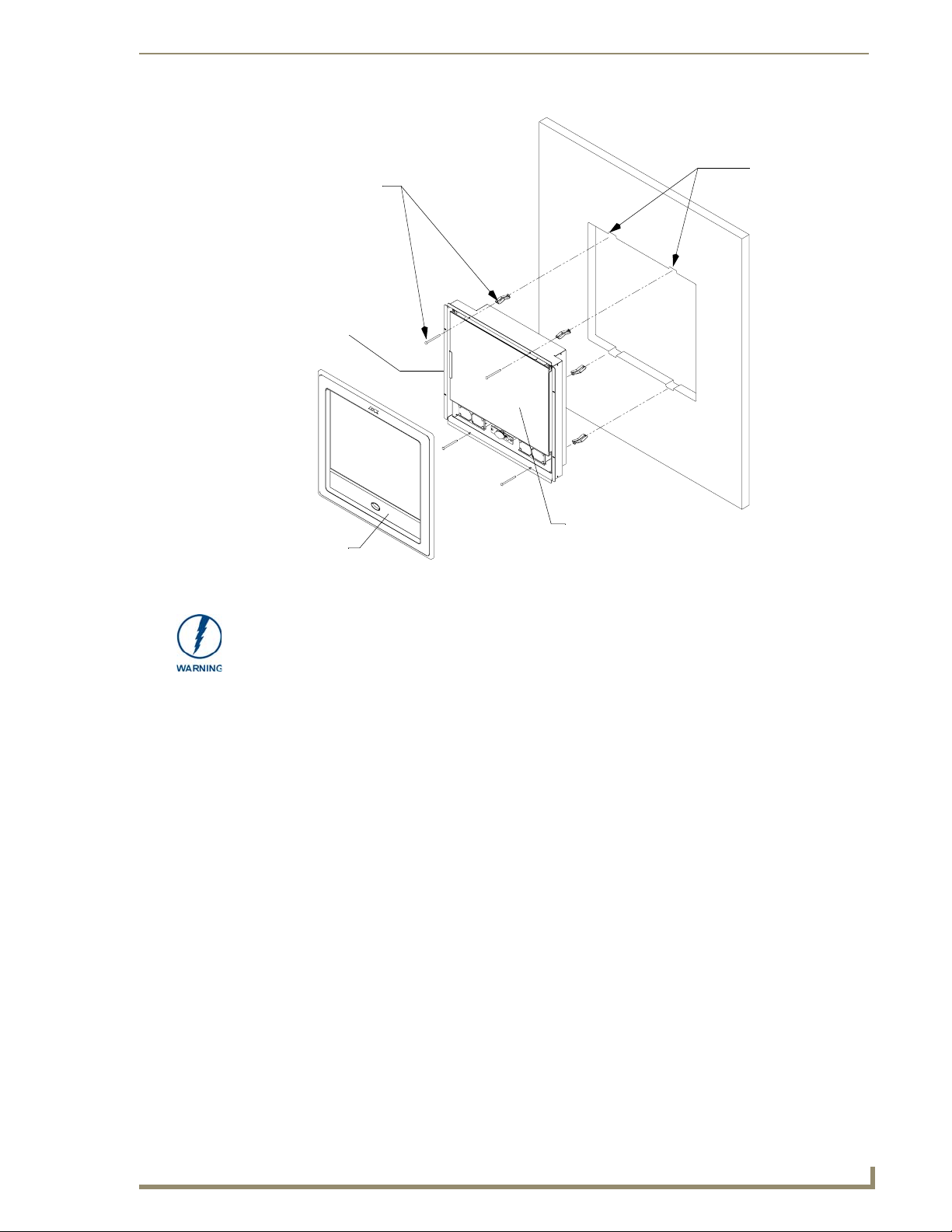
Install the four drywall
clip sets (included)
into these holes
Mounting Tab
Installation Procedures: 12" and 15" Panels
4 notches are
required if the
unit is installed in
drywall using the
four (4) provided
drywall expansion
clips
B - Main NXD unit consists of
A - Faceplate
(bezel)
FIG. 42 Wall Mount panel (NXD) installation configuration for drywall surfaces
the touch panel and housing
The drywall clip set must be re-ordered from AMX if the drywall clip is bent
accidentally during an installation or removed during a re-installation.
11. Place the magnetic faceplate (A in FIG. 42) back onto the main NXD unit (B in FIG. 42). Make sure
to align the Microphone, Light, and PIR Motion sensor locations to their respective openings on the
front bezel/faceplate.
12. Connect the terminal RJ-45, Ethernet, USB, and any optional audio/video wiring to their respective
locations on either the NXA-AVB/RGB Breakout Box, Ethernet port, or NetLinx Master.
13. Reconnect the terminal power connector on the 12 VDC-compliant power supply and apply power.
Installing the NXD into a Flat Surface using #4 screws
Mounting screws (#4, not included) are secured through circular holes located at the left and right sides
of the NXD panel. The most important thing to remember when mounting the NXD is that the
outer frame (Mounting Tabs) must be installed flush against the mounting surface.
It is recommended that you cutout the surface slightly smaller than what is outlined in the
installation drawings so that you can make any necessary cutout adjustments.
1. Prepare the area by removing any screws or nails from the surface before beginning the cutout
process.
2. Cut out the surface for the 12-inch Wall Mount using the dimensions shown in FIG. 43 and for the
15-inch Wall Mount using the dimensions shown in FIG. 44.
VG-Series Modero Touch Panels
63
Page 74

Installation Procedures: 12" and 15" Panels
THESE 4 HOLES ARE ONLY REQUIRED
WHEN MOUNTING UNIT TO A SOLID
SURFACE (PODIUM, DESK, ETC.).
SECURE UNIT WITH #4 SCREWS.
CUTOUT
FRONT BEZEL
FIG. 43 NXD 12-inch Wall Mount panel dimensions using #4 mounting screws
3. Remove the magnetic faceplate/bezel (A in FIG. 45) from the main NXD unit (B in FIG. 45) by
gripping the faceplate and pulling with gentle outward force.
4. Thread the incoming RJ-45, Ethernet, USB, and any other audio/video wiring (from their terminal
locations) through the cutout opening. Refer to the Wiring Guidelines for the 1200VG and 1500VG
Panels section on page 68 for pinout descriptions. Leave enough slack in the wiring to
accommodate any re-positioning of the panel.
64
VG-Series Modero Touch Panels
Page 75

CUTOUT
Installation Procedures: 12" and 15" Panels
FRONT BEZEL
FIG. 44 NXD 15-inch Wall Mount panel dimensions using #4 mounting screws
5. Connect all data and power wiring to their corresponding locations along the side of the
(un-powered) NXD touch panel.
Verify the terminal end of the power cable is not connected to power supply before plugging in
the 2-pin power connector.
The USB connectors can be from a either a USB extension cable, or a wireless USB RF
transmitter.
6. Test the incoming wiring by connecting the panel connections to their terminal locations and
applying power. Verify the panel is receiving power and functioning properly before finalizing the
installation.
7. Disconnect the terminal end of the power cable from the power supply.
Don’t disconnect the connectors from the touch panel. The unit must be installed with
the necessary connectors before being inserted into the solid surface.
8. Carefully slide the main unit into the cutout until the Mounting Tabs of the NXD unit lie flush
against the wall.
9. Insert and secure the four #4 screws into their corresponding holes located along the sides of the
NXD (using a grounded Phillips-head screwdriver) until the unit is secure and flush against the wall.
10. Reinstall the magnetic faceplate (A in FIG. 45) back onto the main NXD unit (B in FIG. 45).
Make sure to align the Microphone, Light, and PIR Motion sensor locations to their respective
openings on the front bezel/faceplate.
VG-Series Modero Touch Panels
65
Page 76

Installation Procedures: 12" and 15" Panels
Install the four (#4)
mounting screws
into the holes
(screws not included)
A - Faceplate
(bezel)
Attachment is done
along the edges of
the cutout
Flat surface
(can include a
wall, podium, or
other flat
surface)
B - Main NXD unit consists of
the touch panel and housing
FIG. 45 Wall Mount panel installation configuration for flat/solid surfaces
11. Reconnect the terminal RJ-45, Ethernet, USB, and any optional audio/video wiring to their
respective locations on either the NXA-AVB/RGB Breakout Box, Ethernet port, or NetLinx Master.
12. Reconnect the terminal power connector on the 12 VDC-compliant power supply and apply power.
Installing an NXD into an (optional) Rack Mount Kit (NXA-RK12 or NXA-RK15)
Remove the magnetic faceplate/bezel from the main NXD unit by gripping the faceplate and pulling
1.
with gentle outward force.
2. Thread the incoming RJ-45, Ethernet, USB, and any optional audio/video wiring through the
opening in the equipment rack (from their terminal locations). Refer to the Wiring Guidelines for
the 1200VG and 1500VG Panels section on page 68 for pinout descriptions. Leave enough slack to
accommodate any re-positioning of the panel.
3. Connect all data and power wiring connectors to their corresponding locations along the side of the
(un-powered) NXD touch panel.
Verify the terminal end of the power cable is not connected to a power supply before plugging
in the 2-pin power connector.
The USB connectors can be from a either a USB extension cable, or a wireless USB RF
transmitter.
4. Test the incoming wiring by connecting the panel connections to their terminal locations and
applying power. Verify the panel is receiving power and functioning properly to prevent repetition
of the installation.
5. Disconnect the terminal end of the power cable from the connected power supply.
66
VG-Series Modero Touch Panels
Page 77

Installation Procedures: 12" and 15" Panels
Don’t disconnect the connectors from the touch panel. The unit must be installed with
the necessary connectors before being inserted into the equipment rack.
6. Insert the main 12-inch Modero unit into an NXA-RK12 (FIG. 46) or the 15-inch Modero into an
NXA-RK15 (FIG. 47).
Rack mount
frame (NXA-RK12)
FIG. 46 NXD 12 inch Wall Mount panel installed into an NXA-RK12 Rack Mount Kit
Rack mount frame
(NXA-RK15)
FIG. 47 NXD 15 inch Wall Mount panel installed into an NXA-RK15 Rack Mount Kit
Faceplate
Faceplate
7. Secure the panel to the NXA-RK frame by first inserting and then tightening the four #4-40 screws
(provided). Line up the four mounting holes and use a grounded Phillips-head screwdriver to tighten
the screws in a clockwise direction.
8. Insert the NXA-RK (with connected NXD unit) into the equipment rack, making sure to align the
screw holes along the sides on the NXA-RK with the holes in the equipment rack.
VG-Series Modero Touch Panels
67
Page 78

Installation Procedures: 12" and 15" Panels
9. Use a grounded Phillips-head screwdriver to secure the NXA-RK (with connected NXD unit) to the
equipment rack using #10-32 screws (not included).
10. Place the magnet faceplate back onto the main NXD unit by gripping the faceplate and placing it on
the housing with gentle force. Make sure to align the Microphone, Light, and PIR Motion sensor
locations to their respective openings on the front bezel/faceplate.
11. Reconnect the terminal RJ-45, Ethernet, USB, and any optional audio/video wiring to their
respective locations on either the NXA-AVB/RGB Breakout Box, Ethernet port, or NetLinx Master.
12. Reconnect the terminal power connector on the 12 VDC-compliant power supply and apply power.
Wiring Guidelines for the 1200VG and 1500VG Panels
These Modero panels use a 12 VDC-compliant power supply to provide power to the panel via the
2-pin 3.5 mm mini-Phoenix PWR connector. Use the previously referenced power requirements to
determine the power draw.
The incoming PWR and GND wires from the power supply must be connected to the corresponding
locations within the PWR connector.
These units should only have one source of incoming power. Using more than one
source of power to the touch panel can result in damage to the internal components
and a possible burn out.
Apply power to the panels only after installation is complete.
Preparing captive wires
You will need a wire stripper and flat-blade screwdriver to prepare and connect the captive wires.
Never pre-tin wires for compression-type connections.
1. Strip 0.25 inch (6.35 mm) of insulation off all wires.
2. Insert each wire into the appropriate opening on the connector (according to the wiring diagrams
and connector types described in this section).
3. Tighten the screws to secure the wire in the connector. Do not tighten the screws excessively; doing
so may strip the threads and damage the connector.
Wiring a power connection
To use the 2-pin 3.5 mm mini-Phoenix connector with a 12 VDC-compliant power supply, the incoming
PWR and GND wires from the external source must be connected to their corresponding locations on the
connector (FIG. 48).
PWR +
GND -
To the Touch Panel
FIG. 48 NetLinx power connector wiring diagram
Power Supply
68
1. Insert the PWR and GND wires on the terminal end of the 2-pin 3.5 mm mini-Phoenix cable. Match
the wiring locations of the +/- on both the power supply and the terminal connector.
2. Tighten the clamp to secure the two wires. Do not tighten the screws excessively; doing so may strip
the threads and damage the connector.
VG-Series Modero Touch Panels
Page 79

Installation Procedures: 12" and 15" Panels
3. Verify the connection of the 2-pin 3.5 mm mini-Phoenix to the power supply.
Audio/Video Port: Connections and Wiring
The following table shows the signal and pinout/pairing information used on the RJ-45 Audio and Video
connections.
Audio/Video RJ-45 Pinout Information
Pin Wire Color Function Polarity
1 Orange/White Right Audio In +
2 Orange Right Audio In -
3 Green/White Video In -
4 Blue Mic Out -
5 White/Blue Mic Out +
6 Green Video In +
7 White/Brown Left Audio In +
8 Brown Left Audio In -
1 2 3 4 5 6 7 8
TIA 568B
1 2 3 4 5 6 7 8
(female) (male)
RJ-45 connector - pin configurations
Refer to the Installing CAT5 Suppression Ferrites section on page 30 for detailed information on how to
install the necessary number of CAT5 Suppression Ferrites on the Black A/V RJ-45 cable connected to
the panel.
Ethernet/RJ-45 Port: Connections and Wiring
FIG. 49 describes the blink activity for the Ethernet 10/100 Base-T RJ-45 connector and cable. The
Ethernet cable is connected to the rear of Table Top and side of the Wall Mount panels.
A - Activity LED (yellow)
lights when receiving or
transmitting Ethernet
data packets
FIG. 49
Layout of Ethernet LEDs
A L
ETHERNET
10/100
L - Link LED (green) lights when
the Ethernet cables are connected
and terminated correctly.
VG-Series Modero Touch Panels
69
Page 80

Installation Procedures: 12" and 15" Panels
The following table lists the pinouts, signals, and pairing associated with the Ethernet connector.
Ethernet RJ-45 Pinouts and Signals
Pin Signals Connections Pairing Color
1 TX + 1 --------- 1 1 --------- 2 Orange-White
2 TX - 2 --------- 2 Orange
3 RX + 3 --------- 3 3 --------- 6 Green-White
4 no connection 4 --------- 4 Blue
5 no connection 5 --------- 5 Blue-White
6 RX - 6 --------- 6 Green
7 no connection 7 --------- 7 Brown-White
8 no connection 8 --------- 8 Brown
12 3 456 78
12 3 456 78
FIG. 50 diagrams the RJ-45 pinouts and signals for the Ethernet RJ-45 connector and cable.
FIG. 50
RJ-45 wiring diagram
70
VG-Series Modero Touch Panels
Page 81

Installation Procedures: 17" Panels
Installation Procedures: 17" Panels
Overview
NXT panels are mounted onto flat (horizontal) surfaces in either a stand-alone or combo (NXT atop an
NXA-BASE/B battery base) configuration. NXD panels are installed into either a pre-wall surface (using
the CB-TP17 conduit/wallbox) or a solid surface (using either solid surface or drywall screws).
Unpacking the Panel
1. Inspect and confirm the contents of the shipment box to verify that you have all specified parts.
Refer to the Specifications section on page 12 for more information about included accessories and
other AMX equipment.
2. Carefully remove the panel from the shipping box.
3. Carefully peel the protective plastic cover from the LCD.
If the protective plastic LCD cover is not removed, the panel may not respond
properly to touch points on the LCD or allow proper screen calibration.
Installing the Internal Components
Installation of the internal components such as the NXA-PCI80211G Wireless card and NXA-RGB
Interface card are described in detail within the following sections:
Step 2: Install the 802.11g mini-PCI Wireless Card section on page 38.
Step 3: Install the NXA-RGB Card Component (NXT) section on page 39.
Upgrading the Back Box with the MB-TP17 VESA Housing
Upgrading the existing back box with the new VESA Mounting Kit (FG033-50) requires 3 main
processes:
Removing the pre-existing back box and installing the new VESA back box.
Threading cables through the strain relief grommet opening in the rear plastic cover.
Finalizing the installation of the NXD (with VESA back box and cables) into the plastic cover,
securing both components, and finalizing the strain relief grommet installation.
The new MB-TP17 Universal VESA Mounting Box uses a standard VESA installation
pattern of 75 mm between holes. VESA mounts that conform to this pattern can be
used on the MB-TP17 Housing.
Removing the Original Modero Back Box
1.
Detach all connectors from the side of the touch panel.
2. Remove the magnetic faceplate from the NXD-1700VG unit by gripping the faceplate and pulling
outwards while applying a small amount of pressure to remove it from the main unit.
3. Place the LCD face-down on a soft cloth to expose the back of the panel and prevent scratching of
the LCD.
VG-Series Modero Touch Panels
71
Page 82

Installation Procedures: 17" Panels
DO NOT REMOVE THE PANEL SECURING SCREWS. These screws secure the
LCD to the metallic casing underneath.
4. Unscrew the Stereo Output nut from the Stereo Output jack.
5. Remove the I/O connector plate by using a grounded Phillips-head screwdriver to remove the two
screws and slide the I/O connector plate away from the back box housing.
6. Remove the four pan-head Housing Screws from the rear of the NXD unit (FIG. 51). These screws
secure the back box to the internal panel casing.
DO NOT
REMOVE
these
panel
securing
screws
DO NOT REMOVE
these panel
securing screws
Unscrew these four Housing Screws to
remove the back box. These make direct
contact with the black outer housing.
FIG. 51 Location of the attachment screws on the NXD back box
DO NOT REMOVE THE FOUR PANEL SECURING SCREWS. These screws secure
the LCD to the metallic casing underneath.
7. Lift the back box housing to separate it from the internal panel casing.
Installing the MP-TP17 Back Box
Unscrew the four pan-head Housing Screws (#8-32) from the MB-TP17 rear plastic cover.
1.
2. Gently place the MB-TP17 back box over the internal panel casing (with the cable routing hole on
the right-side of the panel).
3. Re-install and secure the four pan-head Housing Screws into their pre-drilled holes along the edges
of the MB-TP17 back box (FIG. 52) and secure them using a grounded Phillips-head screwdriver.
4. Place the I/O connector plate back over the connector opening and align the connector locations.
5. Resecure the I/O connector plate (using a grounded Phillips-head screwdriver) and resecure the
Stereo Output nut on the Stereo Output jack.
72
VG-Series Modero Touch Panels
Page 83

DO NOT REMOVE
Installation Procedures: 17" Panels
Ten
#6-32
securing
screws
Connector
opening
Securing
hole locations
(2 on each side)
Internal panel casing
Four (pan-head) Housing Screws
Rear plastic cover
(60-0033-50)
FIG. 52 Location of the attachment screws on the NXD back box and VESA housing
MB-TP17 back box
(62-0033-50)
Strain relief grommet
Rim of the strain relief grommet
should lie flush against enclosure
(Clip facing up)
Four (#8-32) screws
Cable Installation for the MP-TP17 Back Box
Connect the cable connectors (RJ-45, Ethernet, and any other audio/video wiring) to their respective
1.
locations along the side of the touch panel.
2. Use the tie-wrap (45-0009A) to wrap the cables together inside the VESA Mount enclosure. This
cable tie is used to insure the cable will not pull through or work itself through the new larger strain
relief grommet (45-0032-01) over time.
3. Thread the incoming cables through the hole on the rear plastic cover and then through the strain
relief grommet.
4. Slide the grommet along the cable and securely insert it into the opening on the rear plastic cover
(FIG. 52).
Finalizing the installation
Gently place the rear plastic cover over the NXD panel (with LCD and MB-TP17 back box).
1.
2. Insert the protruding cables, coming out from the opening on the rear plastic cover, into the open
strain relief grommet.
3. Allow some slack/length on these cables as a service loop. This service loop provides enough cable
length so you can later remove the NXD (with connected cables) from the rear plastic cover.
VG-Series Modero Touch Panels
73
Page 84

Installation Procedures: 17" Panels
VERIFY THE LENGTH AND LOCATION OF THE INSERTED CABLES. ONCE THE
STRAIN RELIEF GROMMET IS CLOSED, IT IS DIFFICULT TO RE-OPEN.
4. Carefully apply pressure to close the strain relief grommet over the desired cable location.
Verify the Strain Relief Grommet is securely closed over the cables and the clip is
facing the correct direction (upwards). The process of securing the strain relief
grommet may require the use of pliers. Also verify the length and location of the
inserted cables. Once the strain relief grommet is closed, it is difficult to re-open.
5. Firmly push the Strain Relief Grommet into the opening (toward the inside) until the rim is securely
flush against the back of the rear plastic cover (FIG. 53).
6. Securely grasp both sides of the NXD panel (with LCD, MB-TP17 back box, and attached cables),
rotate the entire unit over, and lie it on a flat level surface.
7. Note the available mounting contact surface area on the rear plastic cover (FIG. 53). This area
represents the space available for use with a VESA connector plate.
.83[21MM]
3.83[97MM]
1.84[47MM]
4.06[103MM]
FIG. 53 MB-TP17 Mounting contact surface area
8. Insert and secure the ten #6-32 securing screws into their pre-drilled holes along the edges of the
NXD unit (FIG. 52). This step secures the NXD unit to the rim of the rear plastic cover.
9. Align a VESA mount connector (purchased separately) to the four #8-32 screw holes on the back of
the rear plastic cover (FIG. 53).
10. Insert the four provided #8-32 screws through the VESA mount’s four holes and then into the pre-
drilled holes on the rear plastic cover.
74
When installing a VESA mount to the rear plastic cover, use only the AMX provided
#8-32 screws.
11. Secure these four #8-32 screws to the rear plastic cover by using a grounded Phillips-head
screwdriver. This step secures the VESA mount to the rear of the panel.
VG-Series Modero Touch Panels
Page 85

Rear plastic cover (rear view)
VESA mount connection location
(USE ONLY AMX PROVIDED #8-32 screws)
FIG. 54 Installation of grommet into the rear plastic enclosure
Installation Procedures: 17" Panels
Rim of the strain relief grommet
should lie flush against enclosure
CLIP FACING UP
Refer to your particular VESA mount manufacturer’s installation procedures for further surface
mounting procedures.
Pre-wall Installation of the CB-TP17 Conduit Box
Wall Mount panels (NXDs) are contained within a metallic outer housing (back box). This back box is
not removed when installing the NXD into a Conduit Box (CB-TP17). The back box is only removed to
gain access for the replacement of the Compact Flash component or upgrade to the VESA housing.
INSTALLER: LEAVE A GAP BETWEEN THE STUD AND CONDUIT BOX TO
ACCOMMODATE THE DRYWALL/SHEETROCK. This gap allows the installation of
the drywall/sheetrock after the CB-TP17 has been mounted onto the beams.
The CB-TP17 Conduit/wallbox is an optional metallic box that is secured onto a beam in a pre-wall
setting (where no walls or present). Installation procedures and configurations can vary. This section
describes the installation procedures for the most common installation scenario.
The stud notching and conduit box installation must be done prior to any wall
installation.
The most important thing to remember when mounting this conduit box is that the mounting tabs must
be mounted flush against the outside of the sheetrock. This step determines whether or not the mounting
stud is notched (cutout-out to fit the conduit box).
1. Measure the distance between the inside of the two selected stud beams. Most beams have a
distance of about 14" to 16". This is too narrow to accommodate the 17.072" (43.36 cm) wide
CB-TP17 conduit box.
2. Determine whether one or both of the selected stud beams must be notched (FIG. 55). The
determining factor is the flush alignment of the mounting tabs along the outside of the post-wall
sheetrock.
VG-Series Modero Touch Panels
75
Page 86

Installation Procedures: 17" Panels
3. Cutout the notched beam using a height of 13.554" (34.43 cm) (as shown below in FIG. 55) and a
depth equal to the thickness of the drywall.
Before
~14" to 16"
13.554"
(34.43 cm)
17.07"
(43.36 cm)
Horizontal
support beam
FIG. 55 CB-TP17 conduit box installation into a notched stud (showing before and after installation)
After
Mounting
tabs flush on
the OUTSIDE
of sheetrock
Use a block to secure the
Conduit Box to the
notched stud
The determining factor in the depth of the cut into the beam is the thickness of the
drywall. The mounting tabs MUST BE FLUSH against the drywall and therefore, the
depth of the notch depends on that thickness.
4. Insert one side of the conduit box into the indention on the notched stud and rest the other side of
the box against the opposite beam.
5. Install and secure a shorter horizontal beam below the conduit box. This beam acts to support the
weight of the box from below and should be secured to both vertical beams (at the sides).
6. Fasten the CB-TP17 to the Notched stud/beam through the stud fastening holes, located on the
inside of the conduit box (FIG. 56), by using either nails or screws.
7. Insert a perpendicular block between the Non-Notched stud/beam and the Conduit Box. This
block acts as a bridge to secure the stud/beam to the CB-TP17 along the stud fastening holes located
inside of the box.
8. Secure the perpendicular block to the Non-Notched stud/beam (FIG. 56) by using either nails or
screws.
9. Fasten the CB-TP17 to the block through the stud fastening holes, located on the inside of the
Conduit Box (FIG. 56), by using either nails or screws.
10. Remove any necessary wiring knockouts from the (optional) conduit box (CB-TP17) (FIG. 56)
where the necessary cables are threaded through for connection to the touch panel.
11. Thread the incoming RJ-45, Ethernet, and any other audio/video wiring through the knockouts (use
of the top or bottom knockouts are recommended with this installation). Refer to the Wir ing
Guidelines for the 1700VG Panels section on page 87 for pinout descriptions. Leave enough slack
in the wiring to accommodate any re-positioning of the panel.
12. Install the drywall/sheetrock before inserting the main NXD unit into the CB-TP17.
76
VG-Series Modero Touch Panels
Page 87

Stud
Drywall/sheetrock
Installation Procedures: 17" Panels
Inserted block bridges the gap
between the Conduit Box and
the notched beam
Knockouts should be located on
the left-side of the conduit box,
alongside the connectors
Stud fastening holes
Conduit Box can be
fastened to both
studs)
Use four #8 flat-head
Mounting Screws to secure
the NXD to the CB
Secure Beam to block
Mounting tabs for
NXD Wall Mount panel
should be flush
with the outside
of the sheetrock
FIG. 56 Screw locations for conduit box attachment in a pre-wall installation
Depth depends on the
thickness of the Drywall
Notched stud
Installation of an NXD-1700VG
The NXD-1700VG can be installed either directly into the (optional) CB-TP17 or other solid surface
environment using the two different mounting options: drywall clips or solid surface screws. The
following sections describe mounting the touch panel directly into an installed pre-wall Conduit Box, a
solid surface or drywall, and optional NXA-RK17 Rack Mount Kit.
Installing the NXD-1700VG within a CB-TP17 Conduit Box
The conduit box must be mounted prior to continuing this section. Refer to the procedures in the
Pre-wall Installation of the CB-TP17 Conduit Box section on page 75 for detailed pre-wall installation
instructions. Verify that all necessary cables have been threaded through the knockouts on the conduit
box and the connections have been tested prior to installation of the NXD-1700VG.
1. Remove the magnetic faceplate/bezel (A in FIG. 57) from the main NXD unit (B in FIG. 57) by
gripping the faceplate and pulling with gentle outward force.
2. Verify the incoming RJ-45, Ethernet, and any other audio/video cables have been properly threaded
through the wiring knockouts on the left of the conduit box. Leave enough slack in the wiring to
accommodate any re-positioning of the panel.
3. Connect all data and power wiring connectors to their corresponding locations along the side of the
(un-powered) NXD touch panel.
Verify the terminal end of the power cable is not connected to a power supply before plugging
in the 2-pin power connector.
The USB connectors can be from either a USB extension cable, or a wireless USB RF
transmitter.
VG-Series Modero Touch Panels
77
Page 88

Installation Procedures: 17" Panels
Stud
Support block
Four #8 flat-head
Mounting Screws
(not included)
secure the NXD to
the Conduit Box
A - Faceplate
(bezel)
FIG. 57 Wall Mount panel installation configuration of a CB-TP17 in a pre-wall construction
Mounting Tab
Do not use these
tabs to mount
the conduit /wallbox
These are ONLY used to
secure the main unit to the CB
B - Main NXD unit consists of
the touch panel and backbox housing
C - Optional CB-TP17
conduit/wallbox
4. Test the incoming wiring by connecting the panel connections to their terminal locations and
applying power. Verify the panel is receiving power and functioning properly to prevent repetition
of the installation.
5. Disconnect the terminal end of the power cable from the connected power supply.
Don’t disconnect the connectors from the touch panel. The unit must be installed with
the attached connectors before being inserted into the conduit box.
6. Carefully slide the main NXD unit (B in FIG. 57) into the conduit box, so the Mounting Tab lies
flush against the conduit box (C in FIG. 57).
7. Insert and secure four securing #8 flat-head Mounting Screws into their corresponding holes located
along the sides of the NXD (FIG. 57). These #8 screws are not included within the CB Installation
Kit and must be provided by the installer.
8. Place the magnetic faceplate (A in FIG. 57) back onto the main NXD unit (B in FIG. 57). Make sure
to align the Microphone, Light, and PIR Motion sensor locations to their respective openings on the
front bezel/faceplate.
9. Reconnect the terminal RJ-45, Ethernet, and any optional audio/video wiring to their respective
locations (outside the conduit box) on either the NXA-AVB/RGB, Ethernet port, or NetLinx Master.
10. Reconnect the terminal power connector on the 12 VDC-compliant power supply and apply power.
78
VG-Series Modero Touch Panels
Page 89

Installation Procedures: 17" Panels
Installing the NXD-1700VG into drywall using Expansion Clips
Expansion clips are mounted through the four oval holes located along the rim of the NXD-1700VG. As
the screw is tightened, the clip bends toward the insertion hole and into the wall. This bending creates a
"grip" on the wall by either pressing onto the wall or by securing the drywall between the housing and
the drywall clip.
The most important thing to remember when mounting the NXD-1700VG Wall Mount is that the outer
frame (Mounting Ridge) must be mounted flush against the mounting surface.
Most beams have a distance of about 14" to 16". This is too narrow to accommodate the 17.03"
(43.26 cm) wide outer housing (back box) of the NXD-1700VG.
1. Determine which stud beam configuration to use:
Pre-wall framing is done prior to the drywall installation (local framing instructions vary
based on location and building codes). FIG. 58 shows show to mount and position the main
NXD unit into a pre-wall environment (for use with drywall clips).
There is no notching of a beam in this method. The center vertical beam is cut out,
attached, and secured to two horizontal beams, then further secured into place by an another
offset vertical beam that "frames" the insertion area. This framing method provides a space of
~1.20 inches (30.63 mm) above and below the NXD unit to provide the drywall clips with
room to secure themselves against the drywall.
Enough room must be left
for drywall clips to fold and
collapse above and below
the back box
Offset vertical beam
Refer to the SP2256-11 engineering
drawing on www.amx.com for more
detailed framing information
FIG. 58 NXD-1700VG framing installation overview
With an existing wall in place, continue with steps 3 and 4 to notch one or both selected
beams. There is no horizontal support beam "framing" in this method.
Take into account the width of the cutting blade and the thickness of the drywall surface
when making the cut into the drywall.
*
*
VG-Series Modero Touch Panels
79
Page 90

Installation Procedures: 17" Panels
INSTALLER: LEAVE A GAP BETWEEN THE SURFACE OF THE STUD AND THE
BACK BOX MOUNTING RIDGE TO ACCOMMODATE THE DRYWALL/
SHEETROCK. This gap allows the installation of the drywall/sheetrock after the back
box has been mounted onto the beams.
2. Locate the edges of the two studs used in this installation. The location of the NXD is site dependant
and could involve notching more than one beam.
In this sample installation, the left beam is notched and the back box rests against the
right beam.
3. Remove any screws/nails from the drywall, along the notched beam, before beginning the cutout
process.
4. Cut out the surface for the NXD-1700VG Wall Mount using the dimensions shown in FIG. 59.
Be sure to cut out the four notches along the top and bottom areas to accommodate the four drywall
expansion clips (provided).
*
* Top notches are
not symmetrical
Connectors
Left Side
FIG. 59 NXD-1700VG Wall Mount panel dimensions using expansion clips
*
Right Side
80
5. Remove the magnetic faceplate/bezel (A in FIG. 60) from the main NXD unit (B in FIG. 60) by
gripping the faceplate and pulling with gentle outward force.
6. Follow the procedures outlined within Steps 1 - 5 on page 42 thru page 43 to carefully reinstall the
LCD panel back into the back box housing.
VG-Series Modero Touch Panels
Page 91

Install the four
drywall clip
sets (included) into
these holes
Mounting
Ta b
Four notches are
required if the
unit is installed in
drywall using the
four provided
drywall expansion
clips
Installation Procedures: 17" Panels
13.554"
(34.43 cm)
Notching of one or more
stud beams may be
required if the unit is not
framed into the wall.
B - Main NXD unit consists of
A - Faceplate
(bezel)
FIG. 60 Wall Mount panel (NXD) installation using expansion clips
the LCD panel and back box housing
7. Carefully lay the separated LCD (from the main unit) onto a soft cloth resting on a level surface to
prevent scratching of the LCD.
8. Insert the back box into the cutout to check for fit. Make any adjustments to the dimension of the
cutout to accommodate the back box.
9. Cutout the notched beam (FIG. 59) using a height of 13.554" (34.43 cm) and a depth using the
following guideline. This notched beam is located on the side of the NXD unit furthest away from
the connectors.
Calculate the distance from the edge of the mounting ridge (FIG. 59) to the rear point (on the
box) where the beam touches the back box.
Our example uses 1 3/8" (inches) (on the deepest point of the rear back box).
Calculate the thickness of the drywall/sheetrock. Our example uses 5/8" (inches).
The depth of the notch: 1 3/8" minus 5/8" = 6/8" (inches). This value reflects the cutout depth
necessary for the mounting ridge on the back box to be flush against the surface.
The determining factor in the depth of the cut into the beam is the thickness of the
drywall. The MOUNTING TAB MUST BE FLUSH against the drywall and therefore,
the depth of the notch depends on that thickness.
10. Thread the incoming RJ-45, Ethernet, and any other audio/video wiring (from their terminal
locations) through the cutout opening. Refer to the Wiring Guidelines for the 1700VG
Panels section on page 87 for pinout descriptions. Leave enough slack in the wiring to
accommodate any re-positioning of the panel.
VG-Series Modero Touch Panels
81
Page 92

Installation Procedures: 17" Panels
11. Connect all data and power wiring connectors to their corresponding locations along the side of the
(un-powered) NXD touch panel.
Verify the terminal end of the power cable is not connected to a power supply before plugging
in the 2-pin power connector.
The USB connectors can be from either a USB extension cable, or a wireless USB RF
transmitter.
12. Test the incoming wiring by attaching the panel connections to their terminal locations and applying
power. Verify the panel is receiving power and functioning properly to prevent repetition of the
installation.
13. Disconnect the terminal end of the power cable from the connected power supply.
Don’t disconnect the connectors from the touch panel. The unit must be installed with
the attached connectors before being inserted into the drywall.
14. Follow the procedures outlined within Steps 1 - 5 on page 42 thru page 43 to carefully reinstall the
LCD panel back into the back box housing.
15. Install the four sets of drywall screws and expansion clips into the four oval notch locations along
the top/bottom edges of the main unit (FIG. 60). Make sure the top drywall clip grooves face
upwards and the bottom clip grooves face downwards (so they extend away from the Main unit).
16. Carefully insert the main unit (with expansion clips) into the cutout until the Mounting Tabs
on the NXD unit lie flush against the wall (FIG. 60). Make sure to have the right side of the box
resting against the non-notched beam (on the right) and the connector-side of the unit pressed into
the notched beam (on the left).
Replacement drywall clip sets must be ordered from AMX.
17. Tighten the drywall clip sets (screws and clips) until the Mounting Tabs are securely fastened and
flush against the wall.
18. Place the magnetic faceplate (A in FIG. 60) back onto the main NXD unit. Make sure to align the
Microphone, Light, and PIR Motion sensor locations to their respective openings on the front
bezel/faceplate.
19. Reconnect the terminal RJ-45, Ethernet, and any optional audio/video wiring to their respective
terminal locations on either the NXA-AVB/RGB Breakout Box, Ethernet port, or NetLinx Master.
20. Reconnect the terminal power connector on the 12 VDC-compliant power supply and apply power.
82
VG-Series Modero Touch Panels
Page 93

Installation Procedures: 17" Panels
Installing the NXD-1700VG into a Flat Surface using #6 screws
Mounting screws (#6, not included) are secured through two sets of circular holes located at the left and
right sides of the NXD-1700VG. The most important thing to remember when mounting the NXD
Wall Mount is that the outer frame (Mounting Tabs) must be installed flush against the mounting
surface.
Most beams have a distance of about 14" to 16". This is too narrow to accommodate the 17.03" (43.26
cm) wide outer housing (back box) of the NXD-1700VG.
INSTALLER: LEAVE A GAP BETWEEN THE SURFACE OF THE STUD AND THE
BACK BOX MOUNTING RIDGE TO ACCOMMODATE THE DRYWALL/
SHEETROCK. This gap allows the installation of the drywall/sheetrock after the back
box has been mounted onto the beams.
1. Determine which stud beam configuration to use:
Pre-wall framing is done prior to the drywall installation (local framing instructions vary
based on location and building codes). Mount the main NXD unit into a pre-wall environment
by fitting the right side of the box against a beam, then notching the stud closest to the
connectors (based on FIG. 61 and the depth of the drywall), and using the securing screws to
fasten the unit into place after the drywall has been installed. A horizontal beam can be
installed (framed) below the back box to provide lower support.
With an existing wall in place, continue with steps 3 and 4 to notch one or both selected
beams. There is no horizontal support beam "framing" in this method.
Take into account the width of the cutting blade and the thickness of the drywall surface
when making the cut into the drywall.
2. Locate the edges of the two studs used in this installation. The location of the NXD is site dependant
and could involve notching more than one beam.
In this sample installation, the left beam is notched and the back box rests against the
right beam.
3. Remove any screws/nails from the surface, along the notched beam, before beginning the cutout
process.
4. Follow the procedures outlined within Steps 1 - 5 on page 42 thru page 43 to carefully reinstall the
LCD panel back into the back box housing.
5. Cut out the surface for the Wall Mount using the dimensions shown in FIG. 61.
VG-Series Modero Touch Panels
83
Page 94

Installation Procedures: 17" Panels
FIG. 61 NXD-1700VG Wall Mount panel dimensions using #4 mounting screws
6. Remove the magnetic faceplate/bezel (A in FIG. 62) from the main NXD unit (B in FIG. 62) by
gripping the faceplate and pulling with gentle outward force.
Notching of one or more
stud beams may be
required if the unit is not
framed into the wall.
Install the four (#6)
Mounting Screws
into the holes
(screws not included)
Mounting
Ta b
13.554"
(34.43 cm)
84
A - Faceplate
(bezel)
FIG. 62 Wall Mount panel (NXD) installation using screws
B - Main NXD unit consists of
the touch panel and housing
VG-Series Modero Touch Panels
Page 95

Installation Procedures: 17" Panels
7. Carefully lay the separated LCD (from the main unit) onto a soft cloth resting on a level surface.
This soft cloth prevents scratching during the rest of the installation procedure.
8. Insert the back box into the surface cutout to check for fit. Make any adjustments to the dimension
of the cutout to accommodate the back box.
9. Cutout the notched beam (FIG. 62 on page 84) using a height of 13.554" (34.43 cm) and a depth
using the following guideline. This notched beam is located on the side of the NXD unit furthest
away from the connectors.
Calculate the distance from the edge of the mounting ridge (FIG. 62) to the rear point (on the
box) where the beam touches the back box.
Our example uses 1 3/8" (inches) (on the deepest point of the rear back box).
Calculate the thickness of the surface. Our example uses 5/8" (inches).
The depth of the notch: 1 3/8" minus 5/8" = 6/8" (inches). This value reflects the cutout depth
necessary for the mounting ridge on the back box to be flush against the surface.
The determining factor in the depth of the cut into the beam is the thickness of the
surface. The MOUNTING TAB MUST BE FLUSH against the surface and therefore,
the depth of the notch depends on that thickness.
10. Thread the incoming RJ-45, Ethernet, and any other audio/video wiring (from their terminal
locations) through the cutout opening. Refer to the Wiring Guidelines for the 1700VG
Panels section on page 87 for pinout descriptions. Leave enough slack in the wiring to
accommodate any re-positioning of the panel.
11. Connect all data and power wiring connectors to their corresponding locations along the side of the
(un-powered) NXD touch panel.
Verify the terminal end of the power cable is not connected to a power supply before plugging
in the 2-pin power connector.
The USB connectors can be from either a USB extension cable, or a wireless USB RF
transmitter.
12. Test the incoming wiring by connecting the panel connections to their terminal locations and
applying power. Verify the panel is receiving power and functioning properly before finalizing the
installation.
13. Disconnect the terminal end of the power cable from the power supply.
Don’t disconnect the connectors from the touch panel. The unit must be installed with
the attached connectors before being inserted into the solid surface.
14. Follow the procedures outlined within Steps 1 - 5 on page 42 thru page 43 to carefully reinstall the
LCD panel back into the back box housing.
15. Carefully slide the main unit into the cutout until the Mounting Tabs of the NXD-1700VG unit lie
flush against the wall.
16. Insert and secure the four #6 screws into their corresponding holes located along the sides of the
NXD-1700VG (using a grounded Phillips-head screwdriver) until the unit is secure and flush
against the wall.
17. Place the magnetic faceplate (A in FIG. 62) back onto the main NXD unit. Make sure to align the
Microphone, Light, and PIR Motion sensor locations to their respective openings on the front
bezel/faceplate.
VG-Series Modero Touch Panels
85
Page 96

Installation Procedures: 17" Panels
18. Reconnect the terminal RJ-45, Ethernet, and any optional audio/video wiring to their respective
terminal locations on either the NXA-AVB/RGB Breakout Box, Ethernet port, or NetLinx Master.
19. Reconnect the terminal power connector on the 12 VDC-compliant power supply and apply power.
Installing an NXD into an (optional) Rack Mount Kit (NXA-RK17)
1.
Remove the magnetic faceplate/bezel from the main NXD unit by gripping the faceplate and pulling
with gentle outward force.
2. Thread the incoming RJ-45, Ethernet, and any optional audio/video wiring (from their terminal
locations) through the opening in the equipment rack. Refer to the Wiring Guidelines for the
1700VG Panels section on page 87 for pinout descriptions. Leave enough slack to accommodate
any re-positioning of the panel.
3. Connect all data and power wiring connectors to their corresponding locations along the side of the
(un-powered) NXD touch panel.
Verify the terminal end of the power cable is not connected to a power supply before plugging
in the 2-pin power connector.
4. Test the incoming wiring by connecting the panel connections to their terminal locations and
applying power. Verify the panel is receiving power and functioning properly to prevent repetition
of the installation.
5. Disconnect the terminal end of the power cable from the connected power supply.
Don’t disconnect the connectors from the touch panel. The unit must be installed with
the attached connectors before being inserted into the equipment rack.
6. Insert the main 17-inch Modero unit into the NXA-RK17 (FIG. 63).
Faceplate
482.60
19.00
FIG. 63 NXD-1700VG Wall Mount panel installed into an NXA-RK17 Rack Mount Kit
399.29
15.72
84.03
3.31
86
7. Secure the panel to the NXA-RK17 mount frame by first inserting and then tightening the four
#4-40 screws.
8. Insert the NXA-RK17 (with connected NXD unit) into the equipment rack, making sure to align the
screw holes along the sides of the NXA-RK17 with the holes in the equipment rack.
VG-Series Modero Touch Panels
Page 97

Installation Procedures: 17" Panels
9. Use a grounded Phillips-head screwdriver to secure the NXA-RK17 to the equipment rack using
#10-32 screws (not included).
10. Place the magnetic faceplate back onto the main NXD unit by gripping the faceplate and placing it
on the housing with gentle force. Make sure to align the Microphone, Light, and PIR Motion sensor
locations to their respective openings on the front bezel/faceplate.
11. Reconnect the terminal RJ-45, Ethernet, and any optional audio/video wiring to their respective
terminal locations on either the NXA-AVB/RGB Breakout Box, Ethernet port, or NetLinx Master.
12. Reconnect the terminal power connector on the 12 VDC-compliant power supply and apply power.
Wiring Guidelines for the 1700VG Panels
1700VG panels use a 12 VDC-compliant power supply to provide power to the panel via the 2-pin 3.5
mm mini-Phoenix PWR connector. Use the previously referenced power requirements to determine the
power draw.
The incoming PWR and GND wires from the power supply must be connected to the corresponding
locations within the PWR connector.
These units should only have one source of incoming power. Using more than one
source of power to the touch panel can result in damage to the internal components
and a possible burn out.
Apply power to the panels only after installation is complete.
Preparing captive wires
You will need a wire stripper and flat-blade screwdriver to prepare and connect the captive wires.
Never pre-tin wires for compression-type connections.
1. Strip 0.25 inch (6.35 mm) of insulation off all wires.
2. Insert each wire into the appropriate opening on the connector (according to the wiring diagrams
and connector types described in this section).
3. Tighten the screws to secure the wire in the connector. Do not tighten the screws excessively; doing
so may strip the threads and damage the connector.
Wiring a power connection
To use the 2-pin 3.5 mm mini-Phoenix connector for use with a 12 VDC-compliant power supply, the
incoming PWR and GND wires from the external source must be connected to their corresponding
locations on the connector (FIG. 64).
PWR +
GND -
To the Touch Panel
FIG. 64 NetLinx power connector wiring diagram
Power Supply
1. Insert the PWR and GND wires on the terminal end of the 2-pin 3.5 mm mini-Phoenix cable. Match
the wiring locations of the +/- on both the power supply and the terminal connector.
2. Tighten the clamp to secure the two wires. Do not tighten the screws excessively; doing so may strip
the threads and damage the connector.
VG-Series Modero Touch Panels
87
Page 98

Installation Procedures: 17" Panels
3. Verify the connection of the 2-pin 3.5 mm mini-Phoenix to the power supply.
Audio/Video Port: Connections and Wiring
The following table shows the signal and pinout/pairing information used on the RJ-45 Audio and Video
connections.
Audio/Video RJ-45 Pinout Information
Pin Wire Color Function Polarity
1 Orange/White Right Audio In +
2 Orange Right Audio In -
3 Green/White Video In -
4 Blue Mic Out -
5 White/Blue Mic Out +
6 Green Video In +
7 White/Brown Left Audio In +
8 Brown Left Audio In -
TIA 568B
1 2 3 4 5 6 7 8
1 2 3 4 5 6 7 8
(female) (male)
RJ-45 connector - pin configurations
Refer to the Installing CAT5 Suppression Ferrites section on page 30 for detailed information on how to
install the necessary number of CAT5 Suppression Ferrites on the Black A/V RJ-45 cable connected to
the panel.
Ethernet/RJ-45 Port: Connections and Wiring
FIG. 65 describes the blink activity for the Ethernet 10/100 Base-T RJ-45 connector and cable. The
Ethernet cable is connected to the rear of Table Top and side of the Wall Mount panels.
A - Activity LED (yellow)
lights when receiving or
transmitting Ethernet
data packets
FIG. 65
Ethernet connector (showing communication and connection LEDs)
A L
ETHERNET
10/100
L - Link LED (green) lights when
the Ethernet cables are connected
and terminated correctly.
88
VG-Series Modero Touch Panels
Page 99

Installation Procedures: 17" Panels
The following table lists the pinouts, signals, and pairing associated with the Ethernet connector.
Ethernet RJ-45 Pinouts and Signals
Pin Signals Connections Pairing Color
1 TX + 1 --------- 1 1 --------- 2 Orange-White
2 TX - 2 --------- 2 Orange
3 RX + 3 --------- 3 3 --------- 6 Green-White
4 no connection 4 --------- 4 Blue
5 no connection 5 --------- 5 Blue-White
6 RX - 6 --------- 6 Green
7 no connection 7 --------- 7 Brown-White
8 no connection 8 --------- 8 Brown
12 3 45 6 78
12 3 45 6 78
FIG. 66 diagrams the RJ-45 pinouts and signals for the Ethernet RJ-45 connector and cable.
FIG. 66
RJ-45 wiring diagram
VG-Series Modero Touch Panels
89
Page 100

Installation Procedures: 17" Panels
90
VG-Series Modero Touch Panels
 Loading...