

Page 1
Quick Start Guide
NetLinx Hub Cards and Modules NXC-NH/HS/HE
Overview - NetLinx Hub Cards and Modules
NetLinx Hub Cards distribute ICSP (Internet Control System Protocol)
throughout a NetLinx control system. ICSP packets can move easily between
different kinds of networks including Ethernet, Internet, and the NetLinx (ICSNet)
control bus.
The NetLinx Hub Cards covered in this document are:
• NXC-NH ICSNet Hub Card (FG2060)
• NXC-HS ICSHub Server Card (FG2061)
• NXC-HE ICSHub Expander Card (FG2062)
The NXS-MHS Modules (FG2009) provide enclosures for the Hub Cards. The
NetLinx ICSNet control network branches from a NetLinx Master to ICSNet
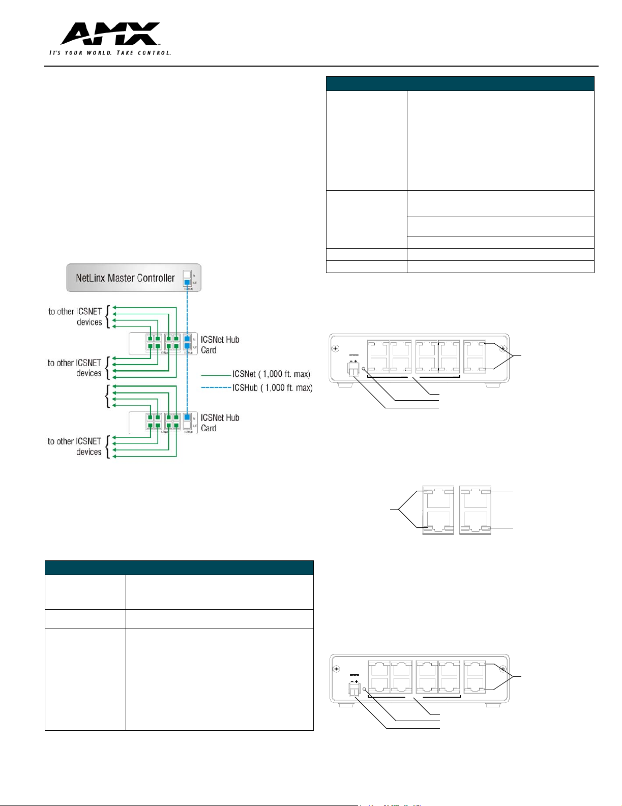
devices via ICSHub data links. An ICSNet Hub Card can then distribute data and
power to up to eight system devices through multiple ICSNet wiring runs. Each
ICSNet wiring run can support up to 16 devices connecting from one to another,
in a daisy-chain fashion. FIG. 1 shows a sample application using a connection
from the Master to the ICSNet Hub Card, then to external ICSNet devices. .
Specifications (Cont.)
ICSHub IN/OUT:
NXC-NH • RJ-45 connectors that supply data to other ICSHubs connected
NXC-HE • RJ-45 connectors that supply data to other Hubs connected to
Optional Accessories:
NXM-MHS module
12 VDC power supply • PS2.8 (FG423-05)
Rack Kit AC-RK Accessory (FG515)
Dimensions (HWD): 1.5" x 5.0" x 8.8" (45 mm x 127 mm x 224 mm)
Weight: 26 oz (737 g)
to the Master Card. The OUT port of one ICSHub must be
connected to the IN connector of a downstream ICSHub Module
or card.
• Yellow LEDs blinks when receiving data on the associated IN/
OUT ports.
the Master Card, and wired using a daisy-chain configuration.
The ICSHub OUT connector of one Hub must be connected to
the ICSHub IN connector on the downstream Hub.
• Yellow LEDs blink when receiving data on the associated IN/OUT
ports.
Metal with black matte finish·
Plastic gray faceplate with translucent viewing window.
• PSN6.5 (FG423-41)
NXC-NH ICSNet Hub Card
The NXC-NH ICSNet Hub Card provides eight ICSNet ports. FIG. 2 shows its
rear panel components. This card connects to external ICSNet devices.
NXC-NH
ICSNet Hub
12VDC
PWR ICSNet
ICSHub
IN
OUT
ICSHub IN/OUT
connectors and LEDs
FIG. 1 Sample ICSNet Hub Card Daisy-chain configuration
ICSHub and ICSNet links can extend up to 1,000 feet (304.8 m). Each link is fully
regenerated at every ICSHub connection to allow systems to connect over
virtually unlimited distances. Hub Cards can be installed in an NXI (NetLinx
Integrated Controller), NXF (CardFrame), or NXM-MHS (Module) for stand-alone
operation.
Specifications
Specifications
Power Requirements:
PWR connector/LED: 2-pin 12 VDC power connector (green); supply depends on load.
ICSNet OUT (NXC-NH): Eight RJ-45 connectors that supply power and data to external
ICSHub OUT (NXC-HS): Nine RJ-45 ports for ICSHub data.
ICSHub IN: NXC-HS RJ-45 connector that supplies data to other NetLinx Controllers and
• NXC-NH - 180 mA @ 12 VDC
• NXC-HS - 160 mA @ 12 VDC
• NXC-HE - 110 mA @ 12 VDC
Green LED lights to indicate power.
ICSNet devices. Max. current draw = 500 mA.
• Yellow LEDs (one per port) blink when sending data on the
associated port(s).
• Yellow LEDs blink when receiving data on the associated OUT
ports.
Hubs, and wired using a daisy-chain configuration. The OUT por t of
one ICSHub must be connected to the IN connector of a
downstream ICSHub Module or Card.
• Yellow LED blinks when receiving data.
ICSNet OUT connectors and LEDs
Power Supply indicator LED (green)
12 VDC Power Supply connector
FIG. 2 NXC-NH Card (shown mounted in NXM-MHS Module - rear view)
Rear Panel LEDs
FIG. 3 shows the layout of the ICSNet and ICSHub LEDs.
ICSHub IN LED (yellow):
ICSNet LEDs (yellow):
light to indicate data
output activity on
these ports
ICSNet
ICSHub
lights to indicate data
IN
input activity on this port
ICSHub IN LED
OUT
(yellow): lights to
indicate data transfer
activity on this port
FIG. 3 Layout of the ICSNet and ICSHub IN/OUT LEDs
NXC-HS ICSHub Server Card
The NXC-HS Server Card provides nine ICSHub OUT ports for connecting
NetLinx Controllers and Hubs, and one ICSHub IN port. FIG. 4 shows its rear
panel components. This card connects to either ICSNet Hubs or other Hub
servers.
NXC-HS
ICSHub Server
12VDC
PWR ICSHub OUT ICSHub
ICSHub OUT connectors and LEDs
Power Supply indicator LED (green)
12 VDC Power Supply connector
IN
OUT
ICSHub
IN/OUT
connectors
and LEDs
FIG. 4 NXC-HS Card/Module (shown mounted in NXM-MHS Module - rear view)
Page 2
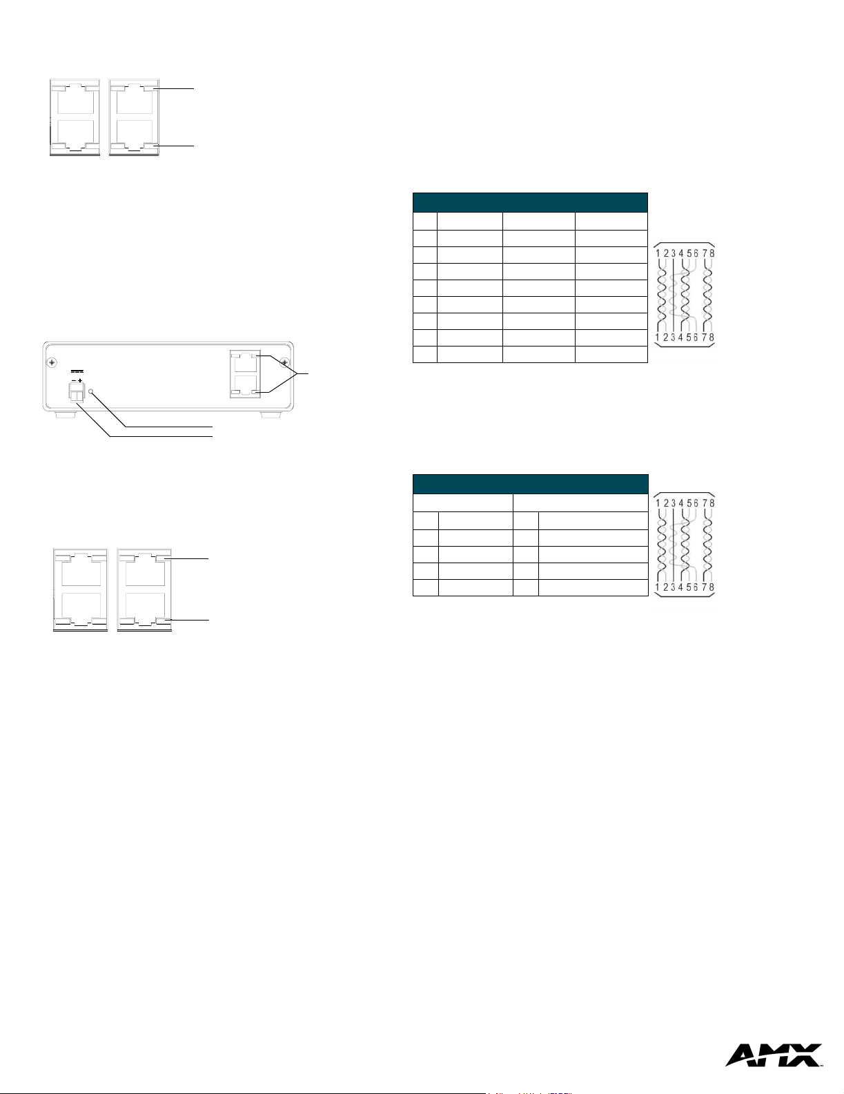
Rear Panel LEDs
FIG. 5 shows the layout of the ICSHub LEDs.
ICSHub IN LED (yellow):
lights to indicate data input
IN
activity on this port
OUT
ICSHub OUT LED (yellow):
lights to indicate data transfer
ICSNet
ICSHub
activity on this port
Preparing/connecting captive wires
1. Strip 0.25 inch of wire insulation off all wires.
2. Insert each wire into the appropriate opening on the connector according
to the wiring diagrams and connector types described in this section.
• Do not tighten the screws excessively; doing so may strip the threads and
damage the connector.
ICSNet RJ-45 Connections/Wiring
The following table shows the pinouts, signals, and pairing information to use
for ICSNet RJ-45 connections. The ICSNet connections provide power and
data to ICSNet devices. Each port provides up to 500 mA of current.
FIG. 5 Layout of the ICSHub IN/OUT LEDs
NXC-HE ICSHub Expander Card
The NXC-HE ICSHub Expander Card can be used as an ICS hub cable
extender where runs between ICS hubs are over 1,000 feet (304.8 m). The
NXC-HE Card can also be used in place of a Master card in a NXI (NetLinx
Integrated Controller) or NXF (CardFrame) to be used as slave devices. FIG. 6
shows its rear panel components.
NXC-HE
ICSHub Expa nder
12VDC
PWR
IN
OUT
ICSHub
Power Supply indicator LED (green)
12 VDC Power Supply connector
ICSHub
IN/OUT
connectors
and LEDs
FIG. 6 NXC-HE Card/Module (shown mounted in NXM-MHS Module - rear view)
Rear Panel LEDs
FIG. 7 shows the layout of the ICSHub LEDs.
ICSHub IN LED (yellow):
lights to indicate data input
IN
activity on this port
OUT
ICSHub OUT LED (yellow):
ICSNet
ICSHub
lights to indicate data transfer
activity on this port
FIG. 7 Layout of the ICSHub IN/OUT LEDs.
ICSNet RJ-45 Pinouts/Signals
Pin Signal Connections Pairing
1 TX + 1 --------- 1 1 --------- 2
2 TX - 2 --------- 2
3 Mic - 3 --------- 3 3 --------- 6
4 GND 4 --------- 4
5 12 VDC 5 --------- 5 4 --------- 5
6 Mic + 6 --------- 6
7 RX + 7 --------- 7 7 --------- 8
8 RX - 8 --------- 8
RJ-45 plug
RJ-45 plug
ICSHub RJ-45 Connections/Wiring
Use CAT5 cables for all ICSHub connections.
Do not connect the last hub in a daisy-chain configuration into the first hub.
The following table shows the pinouts and signals for ICSHub RJ-45
connections.
ISCSHub Pinouts and Signals
IN Port OUT Port
Pin Signal Pin Signal
1TX -1 RX +
2TX +2 RX -
7RX -7 TX +
8RX +8 TX -
RJ-45 plug
RJ-45 plug
Installation and Wiring
Mounting the Modules into an equipment rack
To install the Modules into an equipment rack, you'll need an optional AC-RK
Kit:
1. Remove the front faceplate from the Module to expose the mounting
holes.
2. Mount the module on the AC-RK bracket.
3. Place the AC-RK bracket (with the module) in the equipment rack and
secure the bracket to the rack.
4. Replace the front panel to the Module, and attach the magnetic, translucent faceplate (if necessary).
AMX Corporation reserves the right to alter specifications without notice at any time.
For full warranty information, refer to the AMX Instruction Manual(s) associated with your Product(s).
AMX Corporation. All rights reserved. The AMX logo is a trademark of AMX Corporation. AMX reserves the right to alter specifications without notice at any time.
3000 RESEARCH DRIVE, RICHARDSON, TX 75082 • 800.222.0193 • fax 469.624.7153 • technical support 800.932.6993 • www.amx.com
060-004-2725 02/04 ©2004
93-2062
REV: C
 Loading...