

Page 1
Quick Start Guide
NXC-ME260-64 NetLinx Master Card
For more detailed installation, configuration, programming, file transfer, and
operating instructions, refer to the NXC-ME260-64 Instruction Manual, available
online at www.amx.com.
Overview
The NetLinx NXC-ME260/64 Master Card (FIG. 1) and Module is the controller
for NetLinx Control Systems. The NXC-ME260/64 (FG2010-64) can be installed
in the NetLinx CardFrame (NXF), the NetLinx Integrated Controller (NXI), or in a
NetLinx Module (NXS-MHS) enclosure.
FIG. 1 NXC-ME260/64 Master Card (front view)
ATTENTION!
To utilize the latest security firmware features, verify the Master is using the latest
released firmware. Verify you are using the latest version of NetLinx Studio (available
for download from www.amx.com). After the installation of build 130 (or higher) to the
on-board Master, Telnet security configuration access becomes disabled.
Specifications
NXC-ME260-64 Specifications
Dimensions
(HWD):
Power
Requirement:
Memory: • Compact Flash: 32 MB standard (upgradeable)
Microprocessor: • Coldfire 5407 (32-bit)
Weight: • NXC-ME260/64 only: 0.55 lbs (0.25 kg)
Enclosure: • Metal with black matte finish
Certifications: • FCC Part 15 Class B and CE
Front Panel
Components:
Rear Panel
Connectors:
• 1.5" x 5.0" x 8.8" (45 mm x 127 mm x 224 mm)
• 1 rack unit high
• 750 mA @ 12 VDC
• Power requirements are usage dependant
• Volatile: 64 MB (SDRAM)
• Non-volatile: 1 MB
• Refer to the NXC-ME260/64 Instruction Manual for more
information.
• NXC-ME260/64 with NXS-NMS module: 1.95 lbs (0.88 kg)
• Program Port: RS-232 DB9 connector (male) can be connected to a
DB9 port on a PC. This connector can be used with serial and
NetLinx programming commands, as well as other DB9 capable
devices, to both upload/download information from the NetLinx
Studio program. You set the port's communication speed with the
Baud Rate DIP switch. There are Program ports located on the front
and rear of the Master Card for easy access. Because these ports
share the same circuitry, you should never use both at the same
time; doing so will result in communication and/or programming
errors.
• Status: Green LED blinks to indicate that the system is programmed
and communicating properly.
• Output: Red LED blinks when the Master transmits data, sets
channels On and Off, sends data strings, etc.
• Input: Yellow LED blinks when the Master receives data from button
pushes, strings, commands, channel levels, etc.
• Program Port DIP Switch: Internal 8-position DIP switch on the front
of the card for setting the baud rate for the Program port.
• Power Port: 2-pin 3.5 mm mini-Phoenix (male) connector.
• EXPANSION OUT port: RJ11 connector connects to an AXB-SPE
Slave Port Expander.
• Ethernet Port: LEDs show communication activity, connection
status, speeds, and mode information:
SPD (speed) - Yellow LED lights On when the connection speed is
100 Mbps and turns Off when the speed is 10 Mbps.
L/A (link/activity) - Green LED lights On when the Ethernet cables
are connected and terminated correctly, and blinks when receiving
Ethernet data packets.
• AXlink Port: 4-pin 3.5 mm mini-Phoenix (male) connector that
provides data and power to external control devices.
Power rating = 6 A max; actual load depends on connected power
supply.
• AXlink LED: Green LED indicates the state of the AXlink port.
• Program Port:: 5-pin (male) gray connector for system programming
and diagnostics. There is a Program port located on the front and
rear of the Card for easy access. Because these ports share the
same circuitry, you should never use both ports at the same time.
Doing so will result in communication and/or programming errors.
• ICSNet: Two RJ-45 connectors for ICSNet interface.
• ICSNet LEDs - Indicate activity on that port.
• ICSHub In/Out: RJ-45 connectors provide data to external Hubs
connected to the Master.
• ICSHub IN/OUT LEDs - Indicate activity on that port.
NXC-ME260-64 Specifications (Cont.)
Included
Accessories:
Other AMX
Equipment:
• Connector Bag containing:
- 2-pin 3.5 mm mini-Phoenix connector (female) (41-5025)
- 4-pin 3.5 mm mini-Phoenix connector (female) (41-5047)
- 5-pin 3.5 mm mini-Phoenix connector (female) (41-5053)
- Back panel (51-2010-61)
• Front plate with screws and washers
• Quick Start Guide
• AC-RK Accessory Rack Kit (FG515)
• NXF CardFrame (FG2001)
• NXI Integrated Controller (FG2101)
• NXS-MHS Module (FG2009)
• Upgrade Compact Flash (factory programmed with firmware):
NXA-CFM64M - 64 MB compact flash card (FG2116-01)
NXA-CFM128M - 128 MB compact flash card (FG2116-02)
NXA-CFM256M - 256 MB compact flash card (FG2116-03)
NXA-CFM512M - 512 MB compact flash card (FG2116-04)
NXA-CFM1G - 1 GB compact flash card (FG2116-05)
Ethernet Ports used by the NXC-ME260-64
Ethernet Ports Used
Port type Description Standard Port #
FTP The on-board Master has a built-in FTP server. 21/20 (TCP)
SSH The SSH port uses SSL as a mechanism to configure
Telnet The NetLinx Telnet server provides a mechanism to
HTTP The Master has a built-in web server that complies with
HTTPS/SSL The Master has a built-in SSL protected web server. 443 (TCP)
ICSP Peer-to-peer protocol used for both Master-to-Master
integration!
Solutions
and diagnose a NetLinx system. This port value is used
for secure Telnet communication.
Note: We currently ONLY support SSH version 2.
configure and diagnose a NetLinx system.
the HTTP 1.0 specification and supports all of the
required features of HTTP v1.1.
and Master-to-device communications.
The feature on the Master uses, by default, port 10500
for the XML based communication protocol. This port is
connected to by the client web browser’s JVM when
integration! Solutions control pages are retrieved from
the Master’s web server.
22 (TCP)
23 (TCP)
80 (TCP)
1319 (UDP/TCP)
10500 (TCP)
Modes and LED Blink Patterns
Ethernet 10/100 Rear Panel LED Patterns
Yellow Green
A-activity
Receiving Ethernet data packets.
L-link
Ethernet cables are connected and terminated correctly
Speed
• Transmitting at 100 Mbps
• Transmitting at 10 Mbps
FD-full duplex
• Full duplex mode
• Half duplex mode
The following table lists the modes and blink patterns for the front LEDs.
Modes and Front Panel LED Blink Patterns
Mode Description STATUS
OS Start Starting the operating system. On On On
Boot Master is booting. On Off On
Contacting
DHCP server
Unknown DHCP
server
Downloading
Boot firmware
No program
running
Normal Master is functioning normally. 1 blink per
Master is contacting a DHCP
server for IP config. info.
Master could not find the DHCP
server.
Downloading Boot firmware to the
on-board flash memory. Do not
cycle power during this process!
There is no program loaded, or the
program is disabled.
On Off
Off On
Off
Off
Off
Off
LEDs and Blink Patterns
(green)
On Off Fast Blink
Fast Blink Off Off
Fast Blink Fast Blink Fast Blink
On Off Off
second
OUTPUT
(red)
Indicates
activity
On
Off
On
Off
INPUT
(yellow)
Indicates
activity
Page 2
Program Port Connections/Wiring
The NXC-ME260/64 is equipped with two Program ports. One is located on the
front panel and the other is on the rear for easy access. The port on the front
panel is an RS232 (male) connector and the rear port is a grey 5-pin (male)
connector. Use a Programming cable to connect the Program port to your PC's
COM port to communicate with the Master card. Then, you can download
NetLinx programs to the Master card using the NetLinx Studio 2 software
program.
Wiring a power connection
Use a 12 VDC-compliant power supply to provide power to the Master through
the rear 2-pin 3.5 mm mini-Phoenix. Use the power requirements information
listed in the Specifications table to determine the power draw. The incoming
PWR and GND cable from the PSN power supply must be connected to their
corresponding locations within the PWR connector. Refer to the unit’s
instruction manual for more detailed wiring connection information.
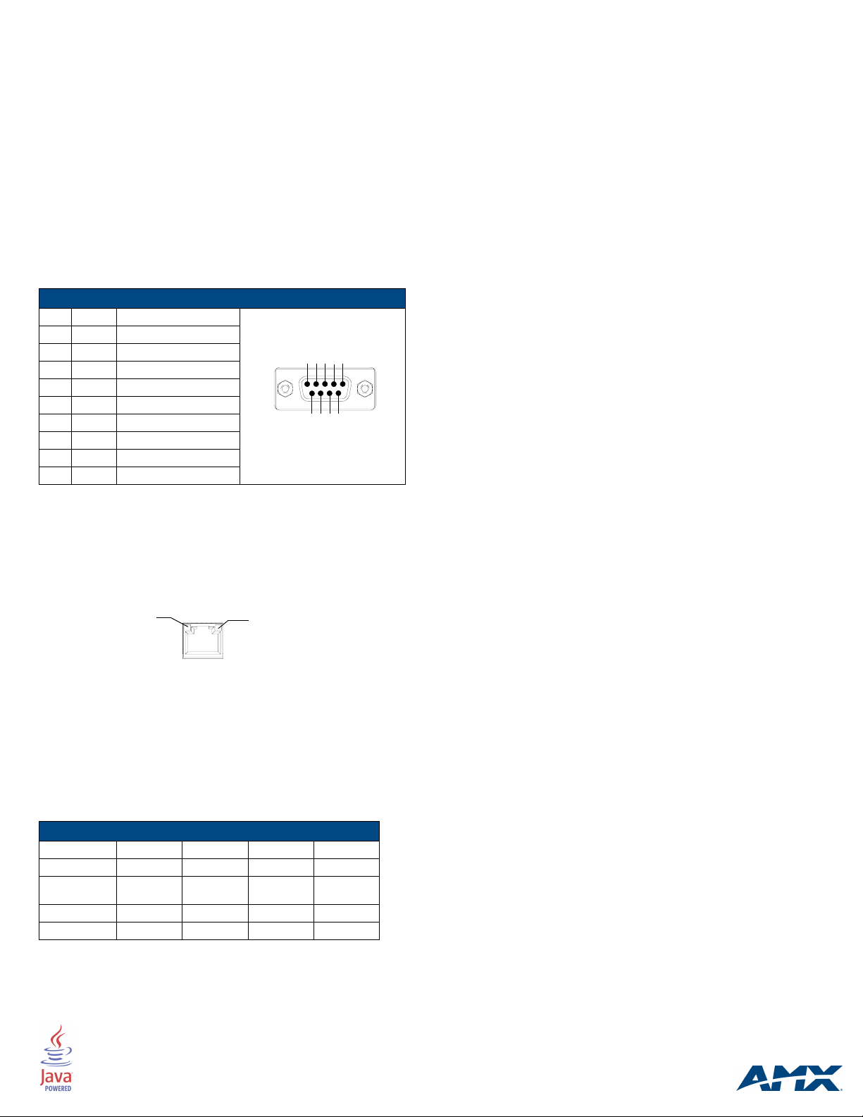
RS-232/422/485 wiring connector information
The following table shows the pinout and wiring specification information for the
front panel RS-232 (DB9) Program Port.
Program Port Connector Pinouts (RS232)
Pin Signal Function
1 N/A Not used
2 RXD Receive data
3 TXD Transmit data
4 DTR Not used
5 GND Signal ground
6 DSR Not used
7 RTS Request to send
8 CTS Clear to send
9 N/A Not used
RJ-45 Connections
Use a standard CAT5 Ethernet cable to provide communication between the
Master and external NetLinx devices.
Ethernet 10/100 Base-T Connector
The Ethernet cable provides 10/100 network connectivity between the panel
and the NetLinx Master (FIG. 2).
L/A - Link/Activity LED lights
(green) when the Ethernet
cables are connected and
terminated correctly.
FIG. 2 Layout of Ethernet LEDs
Baud Rate Settings
The Program Port DIP switch is located on the card’s internal circuit board. For
cards installed in modules, you must remove the front panel to access the DIP
switch. Use this internal DIP switch to set the baud rate used by the Program
port for communication. Use this DIP switch to set the baud rate for the
Program Port, according to the settings shown in the following table. Make sure
the baud rate you set matches the baud rate on your PC's NetLinx COM
Settings before programming the unit.
By default, the baud rate is set to 38,400 (bps).
Baud Rate Settings
Baud Rate Position 5 Position 6 Position 7 Position 8
9600 bps OFF ON OFF ON
38,400 bps
(default)
57,600 bps ON OFF OFF OFF
115,200 bps ON ON ON ON
Note: The Program Port DIP Switch is also used to set Program Run Disable
(PRD) mode. The PRD mode prevents the NetLinx program stored in the
Master from running when you power up the NXC-ME260/64.
OFF ON ON ON
12345
9
678
SPD - Speed LED lights (yellow) when
the connection speed is 100 Mbps
and turns Off when the speed
is 10 Mbps.
Note: DIP switch 1 activates/deactivates the Program Run Disable Mode.
DIP Switches 2,3, and 4 must remain OFF at all times.
Setting the Configuration (Program Port) DIP Switch
1. Disconnect the power supply from the rear 2-pin PWR (green) connector.
2. Set DIP switch positions according to the information listed in the
previous Baud Rate Settings table.
3. Reapply power to the unit.
SPE Port Connection/Wiring
Use an RJ-11 cable to connect the NXC-ME260/64 to an AXB-SPE (FG714)
Slave Port Expander. The EXPANSION OUT port on the rear panel of the
NXC-ME260/64 connects to the EXPANSION IN port on the rear panel of the
AXB-SPE. You can daisy chain multiple AXB-SPE's by connecting the
EXPANSION OUT on the primary AXB-SPE to the EXPANSION IN port on the
secondary. The connecting RJ-11 cable should not exceed 6" in length.
Repeat this process to connect up to nine AXB-SPE's.
Preparing the ME260-64 for Serial Communication
1. Launch NetLinx Studio 2.x (default location is Start > Programs > AMX
Control Disc > NetLinx Studio 2 > NetLinx Studio 2).
2. Select Settings > Master Communication Settings, from the Main
menu, to open the Master Communication Settings dialog box.
3. Click the Communications Settings button to open the Communications
Settings dialog.
4. Click the NetLinx Master radio button (from the Platform Selection
section) to indicate you are working with a NetLinx Master.
5. Click the Serial radio button (from the Transport Connection Option
section) to indicate you are connecting to the Master via a COM port.
6. Click the Edit Settings button (on the Communications Settings
dialog) to open the Serial Settings dialog and set the COM port
parameters (used to communicate to the NetLinx Master).
7. Click the OK button three times to return to the main application.
8. Right-click the Online Tree tab entry and select Refresh System.
9. Assign a System Value by using Diagnostics > Device Addressing from
the Main menu.
10. Enable the Change System selection by clicking on it and then enter the
current and new System values.
11. Click the Change Device/System Number button and when finished
click Done.
12. Select Too ls > Reboot the Master Controller to access the Reboot the
Master dialog, then click Reboot to restart the Master and incorporate
any changes.
13. Once the dialog replies with "Reboot of system complete", click Done and
then click the OnLine Tree tab in the Workspace window to view the
devices on the System.The default System value is one.
14. Right-click on the Empty Device Tree/System entry and select Refresh
System to re-populate the list.
Configuring the ME260-64 for Ethernet Communication
Before continuing, complete the COM port steps above.
1. Connect an Ethernet cable to the unit’s rear Ethernet connector.
2. Select Diagnostics > Network Address from the Main menu and enter
the System, Device (0 for a Master), and Host Name information.
3. To configure the Address:
• Use a DHCP Address by selecting the Use DHCP radio button, then click
the GET IP button (to obtain a DHCP Address from the DHCP Server),
click the SET IP Information button (to retain the new address), and then
finish the process by clicking the Reboot Master > OK buttons.
• Use a Static IP Address by selecting the Specify IP Address radio
button, enter the IP parameters into the available fields, then click the
SET IP Information button (to retain the pre-reserved IP Address to the
Master), and then click the Reboot Master > OK buttons to finish the
process.
4. Repeat steps 1 - 5 from the previous section but rather than selecting the
Serial option, choose TCP/IP and edit the settings to match the IP
Address you are using (whether Static or IP).
5. Click on the Authentication Required radio box (if the Master is
secured) and press the User Name and Password button to enter a
valid username and password being used by the secured Master.
6. Click the OK button three times to return to the main application.
For full warranty information, refer to the AMX Instruction Manual(s) associated with your Product(s).
©2006 AMX. All rights reserved. AMX and the AMX logo are registered trademarks of AMX.
3000 RESEARCH DRIVE, RICHARDSON, TX 75082 • 800.222.0193 • fax 469.624.7153 • technical support 800.932.6993 • www.amx.com
AMX reserves the right to alter specifications without notice at any time.
060-004-2814 6/06
93-2010-64 REV: C
 Loading...