

Page 1
Installation Guide
NXB-KNX NetLinx NXB-KNX Interface
Overview
The NetLinx NXB-KNX interface (FG2031-01) allows AMX NetLinx Integrated
Controllers the ability to control, integrate and communicate with homes and
buildings that utilize the KNX communication protocol.
KNX is the world’s first open, royalty free, and platform independent standard for
home and commercial building control.
(front)
(rear)
FIG. 1 NXB-KNX Interface
Product Specifications
NXB-KNX Specifications
Front Panel
Components:
Rear Panel
Connectors:
Power Requirements: • PoE powered – no local Power Supply needed
Memory: • 64 Mbytes of RAM
Dimensions (HWD): With feet:
Weight: 1.45 lbs. (0.65 kg)
Operating
Environment:
Included Accessories: Black 2-Pin 5mm Phoenix connector with captive screws
Other AMX
Equipment:
Certifications: • FCC Class B
• Status LED (green): Blinks once a second to indicate that
the unit has powered up.
Any state other than blinking once a second indicates the
unit is either not powered, or has not completed boot up.
• KNX LED (green): Solid on indicates power is on and the
unit is connected to KNX bus.
• Output LED (red): Lights to indicate traffic from the
NXB-KNX to the KNX bus.
• Input LED (yellow): Lights to indicate traffic from the KNX
bus to the NXB-KNX.
• KNX 2-pin captive-wire connector:
• Ethernet Port - 10/100 Ethernet with PoE. LEDs show
communication activity, connection status, speeds, and
mode information:
SPD (speed) - Yellow LED lights On when the connection
speed is 100 Mbps and turns Off when the speed is
10 Mbps.
L/A (link/activity) - Green LED lights On when the Ethernet
cables are connected and terminated correctly, and blinks
when receiving Ethernet data packets.
• IEEE 802.3af Compliant
• 256 Mbytes of FLASH
• 1.66" x 5.54" x 4.10"
• 4.216 cm x 14.07 cm x 10.42 cm
Without feet:
• 1.52" x 5.54" x 4.10"
• 3.861 cm x 14.07 cm x 10.42 cm
• Operating Temperature: 32°F - 104°F (0°C - 40°C)
• Relative Humidity: 5% to 85% non-condensing
• Intended for indoor use only
• AC-DIN-CS3 DIN Rail Mounting Bracket (FG532-01)
• PS-POE-AF PoE Injector (FG423-80)
•CE
• IEC60950
•RoHS
Wiring and Connections
Note: To avoid any damage to the electronic component, installation must be
performed in an ESD safe environment.
Note: Do not connect power to the NXB-KNX until the wiring is complete.
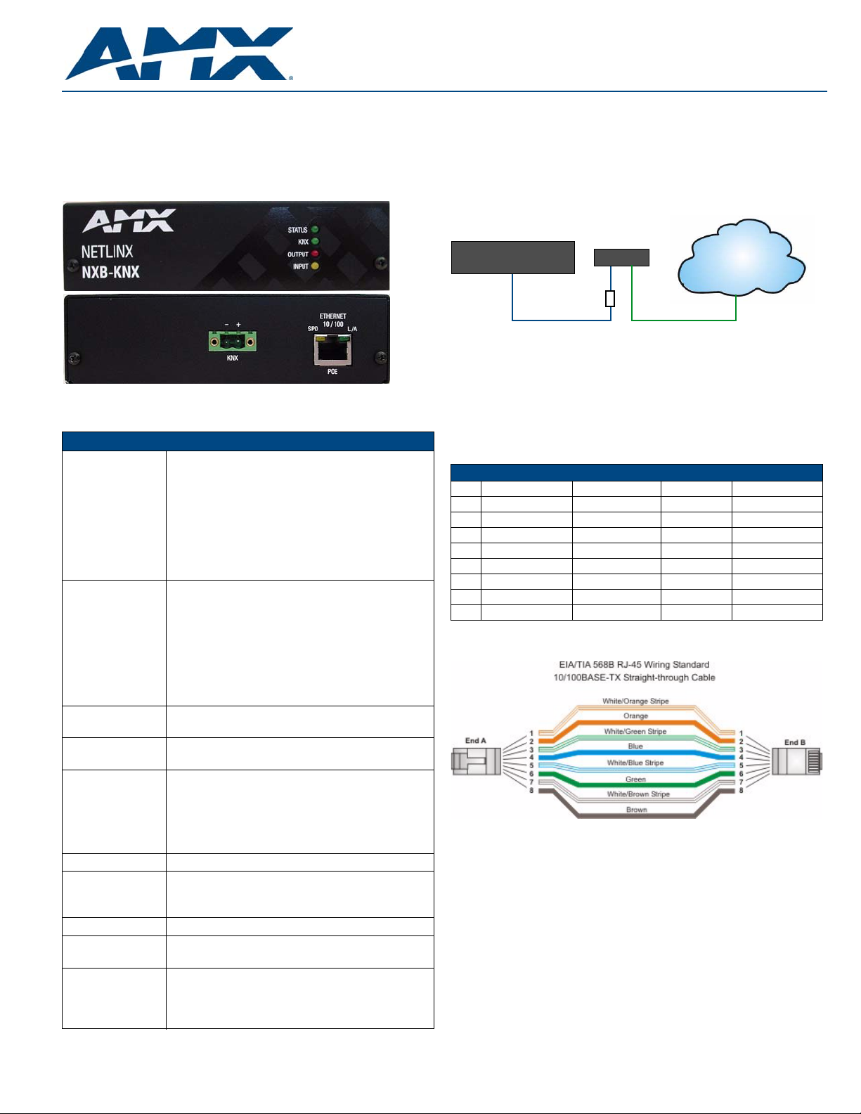
The NXB-KNX is installed between the NetLinx Master and the KNX control bus,
and passes NetLinx control commands to the KNX control bus via 2-wire twisted
pair cabling, as indicated in FIG. 2:
KNX
NXB-KNXNetLinx Master
PoE injector
Ethernet 10/100 2-wire twisted pair
FIG. 2 NXB-KNX installation
After completing the installation, consult the Using the Configuration Manager
section of the NXB-KNX NetLinx Interface Operation/Reference Guide for
instructions on specifying IP and Security settings, via the NXB-KNX
WebConsole.
Ethernet 10/100 Base-T RJ-45 Wiring Configuration
The table below describes the pinouts, signals, and pairing for the Ethernet
10/100 Base-T connector and cable.
Ethernet Pinouts and Signals
Pin Signals Connections Pairing Color
1 TX + 1 --------- 1 1 --------- 2 White-Orange
2 TX - 2 --------- 2 Orange
3 RX + 3 --------- 3 3 --------- 6 White-Green
4 no connection 4 --------- 4 Blue
5 no connection 5 --------- 5 White-Blue
6 RX - 6 --------- 6 Green
7 no connection 7 --------- 7 White-Brown
8 no connection 8 --------- 8 Brown
FIG. 3 diagrams the RJ-45 pinouts and signals for the Ethernet RJ-45 connector
and cable.
Straight-Through Wiring
FIG. 3
PoE (Power Over Ethernet)
The NXB-KNX uses CAT5/CAT6 wire via the Ethernet port for PoE power.
Use the PS-POE-AF Power over Ethernet Injector (FG423-80) to simplify wiring
and installation by eliminating the need for an AC outlet at each point of
installation.
Note: The NXB-KNX can be placed up to approximately 330’ (100 meters) from
the nearest PoE Injector.
• If used with a non PoE-capable Ethernet switch (such as the
NXA-ENET24), then an optional PS-POE-AF Power-over-Ethernet (PoE)
power supply is required to provide power to the NXB-KNX.
• If the NXB-KNX is used with a PoE-capable Ethernet switch (such as the
NXA-ENET24PoE), then no PoE Injectors are required.
Control
Bus
Page 2
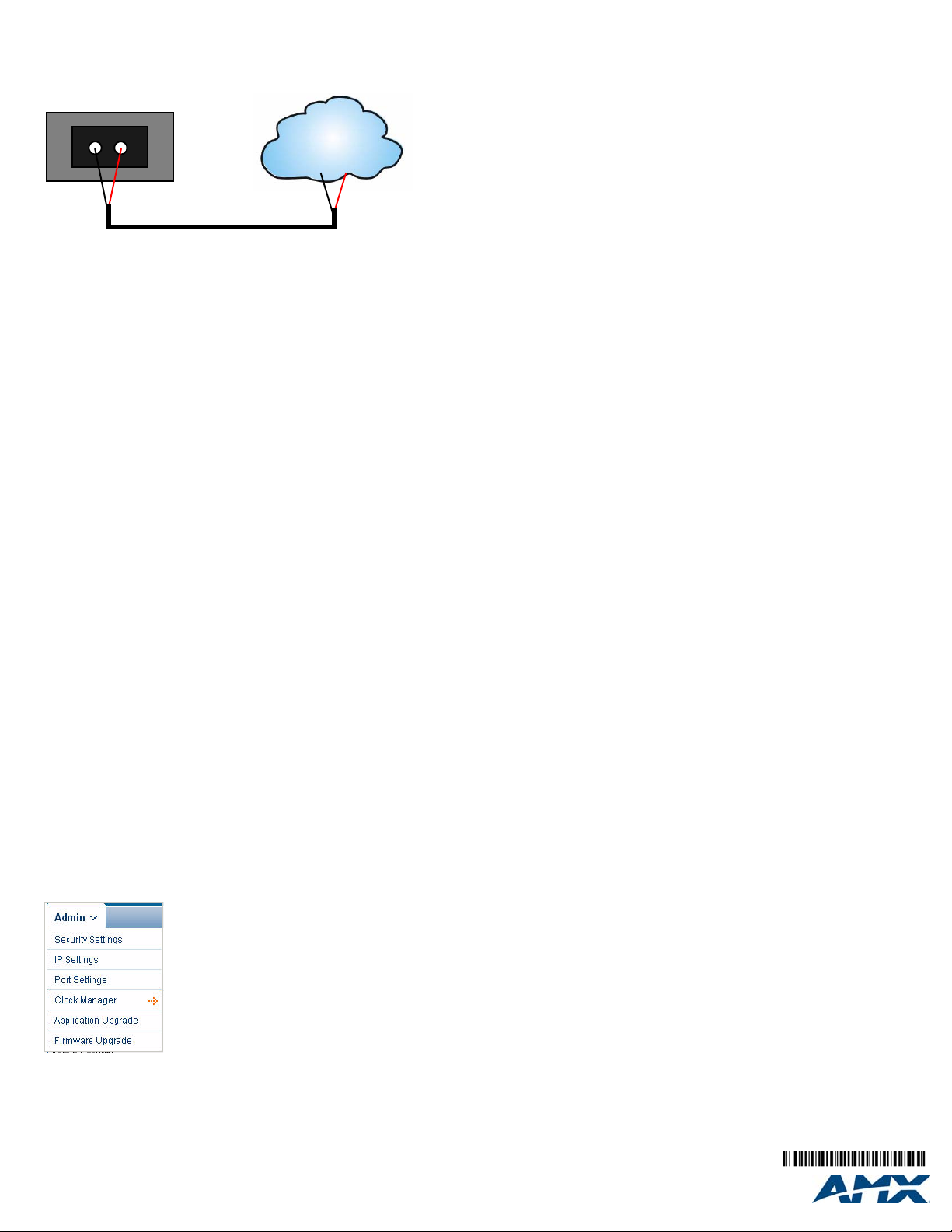
KNX Connector
The KNX connector on the rear panel is a 2-pin captive-wire connector that
provides communication between the NXB-KNX and the KNX control system
via 2-wire shielded twisted pair cabling (FIG. 4).
-
+
KNX
Control
Bus
2-wire twisted pair
FIG. 4 KNX Connector wiring diagram
Configuration
NXB-KNX units have a built-in WebConsole that allows you to make various
configuration settings via a web browser on any PC that has access to the
Master. The web console consists of a series of web pages that are collectively
called the "NXB-KNX Configuration Manager".
Determining the IP Address of the NXB-KNX
NXB-KNX units feature a built-in zero-configuration networking client that
allows you to determine the unit’s IP address via Bonjour or a similar zeroconfiguration client. Zeroconf (also known as "Bonjour") technology provides a
general method to discover services on a local area network. In essence, it
allows you to set up a network without any configuration, as described below.
Zero-Configuration (Bonjour) Client
You will need a zero-configuration client to determine the IP address of the
NXB-KNX. There are many zero-configuration clients available. However, for
the purposes of this document, we will refer to the Bonjour plugin for Internet
Explorer. It is free and widely available for download.
If you don’t already have it installed on your PC, download and install Bonjour
for Windows before you begin.
Note: The NXB-KNX is set to DHCP by default. Bonjour requires DHCP to
discover the device, so don’t change this setting until you have identified the
unit on your network.
1. With Bonjour for Windows running on a PC that has access to the LAN
that the NXB-KNX resides on, connect the NXB-KNX to the network (see
the Wiring and Connections section).
2. In Bonjour, you will see the unit join the network at power up.
3. In Bonjour, click on the NXB-KNX link and it will access the unit's
Configuration Manager (IP Settings page).
4. The unit’s IP Address is displayed in the IP Settings page.
At this point you can assign a new IP Address if necessary.
Accessing the WebConsole
From any PC that has access to the LAN that the NXB-KNX resides on:
1. Open a web browser and type the IP Address of the target NXB-KNX unit
in the Address Bar.
2. Press Enter to access the WebConsole for the specified NXB-KNX unit.
The initial view is the IP Settings page.
Admin Menu
There are several configuration pages included in the Configuration Manager,
all of which are accessed via the Admin drop-down menu (FIG. 5):
Security Settings
Select Security Settings from the Admin drop-down menu to open the
Security Settings page. Use the options on the page to specify security options
and login information for this NXB-KNX unit.
Enable / Disable Security Settings
Web Se curity : Click this checkbox to enable Web Security.
Telnet Security: Click this checkbox to enable Telnet Security.
Admin Security: Click this checkbox to enable Admin Security.
Restore Factory
Defaults:
When Web security is enabled, a username and password are
required to access any system Web pages (default =
disabled).
With Telnet Security enabled, a username and password are
required to establish a Telnet or SSH connection
(default = disabled).
With Admin Security enabled, a username and password are
required to modify any system configuration item (default =
disabled).
Click to restore all security settings to their factory default (all
disabled).
Login Information
Use this set of options to specify a Username and Password. These will be
required only if one or more of the Security Settings are enabled.
Username: Enter the Username that will be required to login to this unit
New Password: Enter a new password that will be required to login to this
Confirm Password: Re-enter the new password in this field.
Restore Factory
Defaults:
id security is enabled.
unit if security is enabled.
Click to restore the login information to the factory defaults:
• Default Username = administrator
• Default Password = password
•Click Accept to save your changes, changes on this page take effect
immediately.
•Click Cancel to cancel any changes.
IP Settings
Select IP Settings from the Admin drop-down menu to open the IP Settings
page. Use the options on the page to specify network/IP settings for this
NXB-KNX unit.
DHCP: Click to toggle DHCP on this unit (default = enabled).
Hostname: Enter a Hostname for this unit (enabled only if DHCP is
IP Address: Enter an IP Address for this unit (enabled only if DHCP is
Subnet Mask: Enter a Subnet Mask for this unit (enabled only if DHCP is
Gateway: Enter a Gateway for this unit (enabled only if DHCP is disabled).
Domain Suffix: Enter the Domain Suffix for this unit.
DNS 1, 2, 3: Enter up to three DNS addresses for this unit.
Reboot: Click to initiate a system reboot. IP Settings changes only take
Note: DHCP must be enabled in order for the zero-configuration
client (i.e. Bonjour for Windows) to detect the NXB-KNX on the
network.
disabled.
disabled).
disabled).
effect after a reboot.
Additional Documentation
Refer to the NXB-KNX Operation/Reference Guide (available to view/download
at www.amx.com) for additional configuration information, including instructions
on using the Clock Manager, Application and Firmware upgrades.
FIG. 5 NXB-KNX Configuration Manager -Admin menu
Click on an option in this menu to access each of the configuration pages, as
described in the following sub-sections:
For full warranty information, refer to the AMX Instruction Manual(s) associated with your Product(s).
©2008 AMX. All rights reserved. AMX and the AMX logo are registered trademarks of AMX.
3000 RESEARCH DRIVE, RICHARDSON, TX 75082 • 800.222.0193 • fax 469.624.7153 • technical support 800.932.6993 • www.amx.com
AMX reserves the right to alter specifications without notice at any time.
8/08
93-2031-01 REV: C
 Loading...