

Page 1

Operation/Reference Guide
NXA-UPS1500
Uninterruptible Power Supply
US version (110 Vac)
Int’l version (220 Vac)
Last Revised: 11/17/2006
Page 2

AMX Limited Warranty and Disclaimer
AMX warrants its products to be free of defects in material and workmanship under normal use for three (3) years from
the date of purchase from AMX, with the following exceptions:
• Electroluminescent and LCD Control Panels are warranted for three (3) years, except for the display and touch
overlay components that are warranted for a period of one (1) year.
• Disk drive mechanisms, pan/tilt heads, power supplies, and MX Series products are warranted for a period of one
(1) year.
• AMX Lighting products are guaranteed to switch on and off any load that is properly connected to our lighting
products, as long as the AMX Lighting products are under warranty. AMX does guarantee the control of dimmable
loads that are properly connected to our lighting products. The dimming performance or quality cannot be guaranteed due to the random combinations of dimmers, lamps and ballasts or transformers.
• Unless otherwise specified, OEM and custom products are warranted for a period of one (1) year.
• AMX Software is warranted for a period of ninety (90) days.
• Batteries and incandescent lamps are not covered under the warranty.
This warranty extends only to products purchased directly from AMX or an Authorized AMX Dealer.
All products returned to AMX require a Return Material Authorization (RMA) number. The RMA number is obtained
from the AMX RMA Department. The RMA number must be clearly marked on the outside of each box. The RMA is
valid for a 30-day period. After the 30-day period the RMA will be cancelled. Any shipments received not consistent
with the RMA, or after the RMA is cancelled, will be refused. AMX is not responsible for products returned without a
valid RMA number.
AMX is not liable for any damages caused by its products or for the failure of its products to perform. This includes any
lost profits, lost savings, incidental damages, or consequential damages. AMX is not liable for any claim made by a
third party or by an AMX Dealer for a third party.
This limitation of liability applies whether damages are sought, or a claim is made, under this warranty or as a tort claim
(including negligence and strict product liability), a contract claim, or any other claim. This limitation of liability cannot
be waived or amended by any person. This limitation of liability will be effective even if AMX or an authorized representative of AMX has been advised of the possibility of any such damages. This limitation of liability, however, will not
apply to claims for personal injury.
Some states do not allow a limitation of how long an implied warranty last. Some states do not allow the limitation or
exclusion of incidental or consequential damages for consumer products. In such states, the limitation or exclusion of
the Limited Warranty may not apply. This Limited Warranty gives the owner specific legal rights. The owner may also
have other rights that vary from state to state. The owner is advised to consult applicable state laws for full determination of rights.
EXCEPT AS EXPRESSLY SET FORTH IN THIS WARRANTY, AMX MAKES NO OTHER WARRANTIES,
EXPRESSED OR IMPLIED, INCLUDING ANY IMPLIED WARRANTIES OF MERCHANTABILITY OR FITNESS FOR
A PARTICULAR PURPOSE. AMX EXPRESSLY DISCLAIMS ALL WARRANTIES NOT STATED IN THIS LIMITED
WARRANTY. ANY IMPLIED WARRANTIES THAT MAY BE IMPOSED BY LAW ARE LIMITED TO THE TERMS OF
THIS LIMITED WARRANTY.
Page 3

Table of Contents
Table of Contents
NXA-UPS1500 Uninterruptible Power Supply ....................................................1
Overview .................................................................................................................. 1
Features.................................................................................................................... 1
Product Specifications ............................................................................................. 2
Front Panel LCD........................................................................................................ 3
IMPORTANT SAFETY INSTRUCTIONS ................................................................5
Important Notice ...................................................................................................... 5
Storage Instructions.................................................................................................. 5
Setting Up The NXA-UPS1500 ...........................................................................7
Place the UPS Properly ............................................................................................. 7
Unpacking................................................................................................................. 7
Accessories for Tower and Rack Mount .......................................................................... 7
Selecting Installation Position ................................................................................... 8
UPS Setup................................................................................................................. 8
Tower Setup ............................................................................................................. 9
Tower Setup - Step One ................................................................................................. 9
Tower Setup - Step Two ................................................................................................. 9
Rack-Mount Setup .................................................................................................. 10
Rack-Mount Setup - Step One ...................................................................................... 10
Rack-Mount Setup - Step Two ...................................................................................... 10
Rack-Mount Setup - Step Three ................................................................................... 11
Rack-Mount Setup - Step Four ..................................................................................... 11
Rack-Mount Setup - Step Five ...................................................................................... 12
Installation ........................................................................................................13
Connect Utility and Load ........................................................................................ 13
Connect Network Surge Protection........................................................................ 14
Connect the RS-232 Communication Port............................................................... 14
RS-232 Communication Port Pin Assignment ................................................................ 15
Operation .........................................................................................................17
Turn On the UPS ..................................................................................................... 17
Turn Off the UPS..................................................................................................... 17
Plug-In Charge ........................................................................................................ 17
Auto-Restart ........................................................................................................... 17
Alarm Silence .......................................................................................................... 17
Self Test.................................................................................................................. 17
NXA-UPS1500 Uninterruptible Power Supply
i
Page 4

Table of Contents
Battery Replacement ........................................................................................19
Overview ................................................................................................................ 19
Assembling the Battery Pack......................................................................................... 19
Replacing the UPS Battery - Step One ......................................................................... 20
Replacing the UPS Battery - Step Two ......................................................................... 21
Replacing the UPS Battery - Step Three ....................................................................... 21
Recycling the Used Battery ........................................................................................... 21
NXA-UPS1500 EPM Installation ........................................................................23
Overview ................................................................................................................ 23
IMPORTANT SAFETY INSTRUCTIONS .................................................................... 23
SAVE THESE INSTRUCTIONS ........................................................................................ 23
IMPORTANT NOTICE .................................................................................................... 24
EPM Specifications.................................................................................................. 24
EPM - Installation and Operation............................................................................ 25
Unpacking ..................................................................................................................... 25
Selecting Installation Position........................................................................................ 25
EPM Installation Instructions................................................................................... 26
Tower Installation - Step One ....................................................................................... 26
Tower Installation - Step Two ....................................................................................... 26
Using the EPM With The UPS.................................................................................. 27
Use With UPS - Step One ........................................................................................... 27
Use With UPS - Step Two ........................................................................................... 27
EPM - Rack Mount Installation ................................................................................ 28
Rack Mount Installation - Step One .............................................................................. 28
Rack Mount Installation - Step Two .............................................................................. 28
Rack Mount Installation - Step Three ............................................................................ 29
Rack Mount Installation - Step Four ............................................................................. 29
Connecting the EPM To the UPS ............................................................................ 30
EPM - Storage Instructions ..................................................................................... 30
Replacing the Battery In the EPM ........................................................................... 31
Replacing the Battery in the EPM - Step One .............................................................. 31
Replacing the Battery in the EPM - Step Two .............................................................. 31
Replacing the Battery in the EPM - Step Three ............................................................ 32
Replacing the Battery in the EPM - Step Four .............................................................. 32
ii
NXA-UPS1500 Uninterruptible Power Supply
Page 5

NXA-UPS1500 Uninterruptible Power Supply
NXA-UPS1500 Uninterruptible Power Supply
Overview
The NXA-UPS1500 is an Uninterruptible Power Supply (UPS) featuring Double AVR Boost and Double
Buck, Pure Sine Wave Output, LCD Display and Hot-Swappable Battery. The NXA-UPS1500 supports
RS232 control.
The NXA-UPS1500 UPS is available in two models - the 120V version (FG678-15) is suitable for use in
the US, and the 220V version (FG678-20), for International usage.
The NXA-UPS1500 features tower/rack-convertible design making it ideal for use with AMX’s line of
MAX devices (FIG. 1).
Release tabs
Battery Compartment
Front Panel LCD
(front)
Input Breaker
RS232 Communication Port
USB Communication Port
DIP Switch
RJ-45 Ports (Network Surge Protection)
FIG. 1 NXA-UPS1500 Uninterrupted Power Supply
Output Breaker
Power Outlets
Input Power Socket (Inlet)
External Battery Terminal
Features
Sine Wave Output provides assurance of compatibility with all kinds of loads.
LCD panel displays system status including load level, battery level, AVR-Boost/Buck and
fault status for easy service.
90% High Efficiency in Normal Mode meets high energy saving standard and reduces noise
and heat generated by other topology UPS.
Easy Swappable Battery Function may save the time and money by swapping the batteries by
end-user without sending it back for a factory service.
Cold Start Function enables to turn on the UPS without connecting to the Utility.
User-friendly Plug and Play design can easily be installed.
The NXA-UPS1500 EPM Extended Power Module (FG 678-15), available as an optional
accessory, works with the NXA-UPS1500 to increase the duration of backup power, providing
up to 3X additional battery run time.
(rear)
NXA-UPS1500 Uninterruptible Power Supply
1
Page 6

NXA-UPS1500 Uninterruptible Power Supply
Product Specifications
NXA-UPS1500 Product Specifications
Available Models: • US version (110 Vac) - FG 678-15
Input:
Voltage Window:
(DIP Switch selectable)
Frequency 45 ˜ 65Hz (50/60Hz auto-sensing)
Output:
Voltage Window (AC Mode): • US version - 110/115/120 Vac +8% ˜ -12%
Voltage Window (INV Mode): US version - 110/115/120 Vac +/-5%
Capacity (VA/W): 1500/900
Wave Form: Pure sine wave
Frequency: 50Hz/60Hz +/-0.1Hz
Transfer Time: 2 ms typical
Autonomy: > 8 min.
DC Start: Yes
Battery:
Type: 12V, sealed lead acid maintenance-free
Capacity: 9AH
Quantity: 4 12V batteries required (included with the US/120V version)
Voltage: 24 Vdc
Recharge Time: 2 ˜ 4 hours to 90%
Storage: • Store at -15 to +30 °C (+5 to +86 °F), charge the UPS battery every 6
Display:
LED: • Utility mode
LCD: • Load level (%)
• Int’l version (220 Vac) - FG 678-20
• US version - 110/115/120 Vac +35% ˜ -32%
• Int’l version - 220/230/240 Vac +35% ˜ -32%
• Int’l version - 220/230/240 Vac +8% ˜ -12%
Int’l version - 220/230/240 Vac +/-5%
months.
• Store at +30 to +45 °C (+86 to +113 °F), charge the UPS battery every 3
months.
• Backup mode
• Battery conditions
• Battery level (%)
•Bypass
• AVR-Boost/AVR Buck
• Battery Low/Replace/Fault
• UPS Fault
• Site Wiring Fault
• Overload
2
NXA-UPS1500 Uninterruptible Power Supply
Page 7
NXA-UPS1500 Uninterruptible Power Supply
NXA-UPS1500 Product Specifications (Cont.)
Protection:
Overload: • AC Mode: >110% Buzzer continuously alarms, and shuts down in 10
minutes.
• Inverter Mode: >120% Buzzer continuously alarms, and shuts down in 10
seconds.
Self-Diagnostics: Upon Power-on
Short Circuit: • AC Mode: Breaker and electronic circuit
• Inverter Mode: Shut down automatically in 8 cycles
Alarms:
Audible and Visual: • Line Failure
• Battery Low
• Overload and Fault
Environment:
Operation Temperature: 32° - 104°F (0-40° C)
Operation Humidity: 95% RH Maximum, non-condensing
Dimensions (HWD): • 3.46” x 17.32” x 18.97” (8.80cm x 44.0cm x 48.2 cm)
• 2U rack height
Control Communication: RS-232
Certifications: • EN50091-1-1:1996 (Safety)
• FCC Part 15, Subpart B - Class A
Included Accessories • AC Input Power Cord
• Four 12V batteries (57-0678-SA) - included with the US/120V version only
• Tower and rack-mounting accessories
Other AMX Equipment: • NXA-UPS1500 EPM Extended Power Module (FG 678-16)
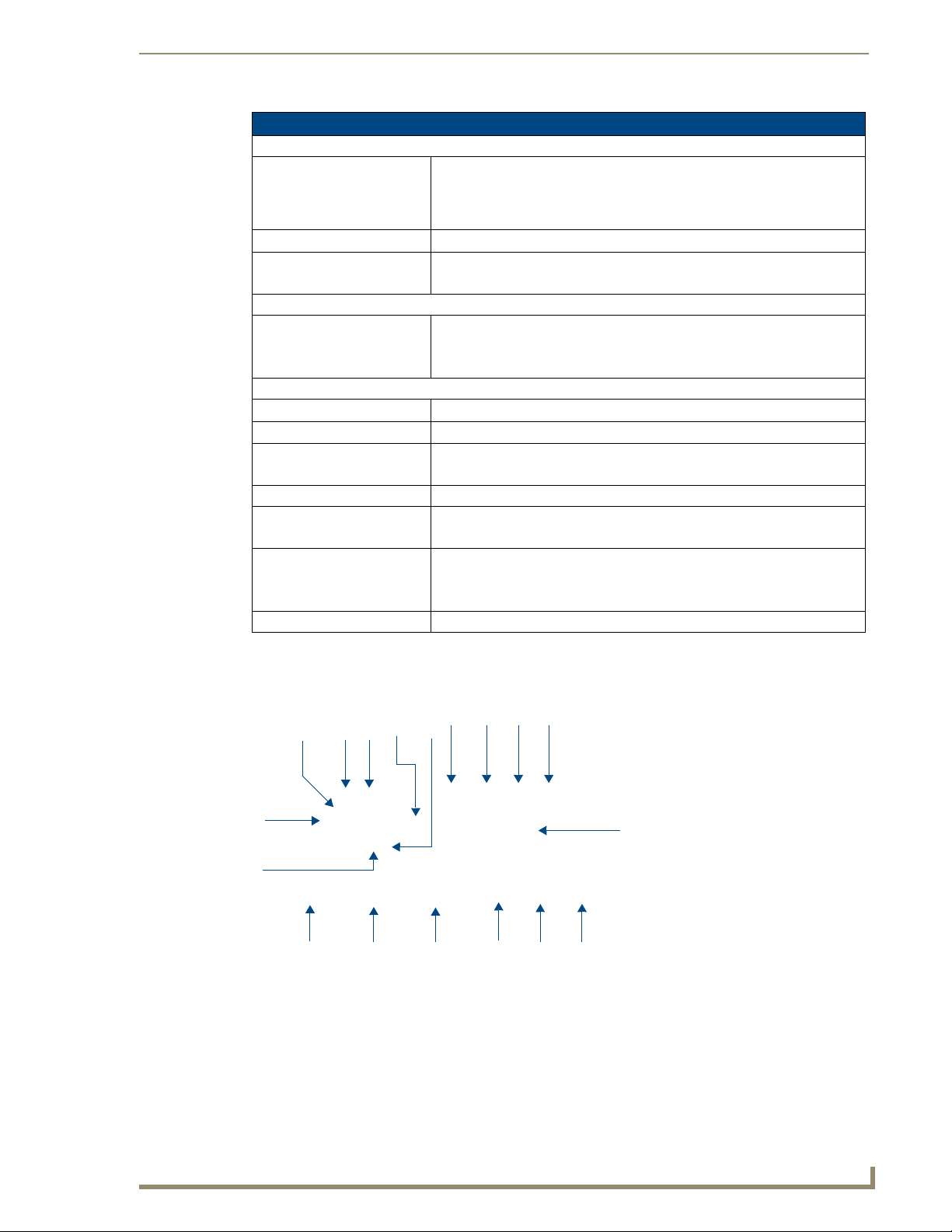
Front Panel LCD
FIG. 2 describes the elements of the front panel LCD:
2
891011
1
7
Elements Of The Front Panel LCD
FIG. 2
5
12 13
6
15
6
1. Utility (Green LED)
2. Fault (Red LED)
3. On Switch
4. Off Switch
5. Battery Replacement
6. Battery Backup (Amber LED)
7. Battery Low
14
8. Bypass
9. Utility Low, UPS Boost
10. Utility High, UPS Buck
11. UPS Output Indicator
12. Polarity Error or Ground Fault
13. Overload
14. Load/Battery Level (%)
15. Load/Battery Level
Indication Control Button
1234
NXA-UPS1500 Uninterruptible Power Supply
3
Page 8

NXA-UPS1500 Uninterruptible Power Supply
4
NXA-UPS1500 Uninterruptible Power Supply
Page 9

IMPORTANT SAFETY INSTRUCTIONS
IMPORTANT SAFETY INSTRUCTIONS
Important Notice
The UPS has its own internal energy source (battery). Should the battery be switched on when
no AC power is available, there could be voltage at the output sockets.
Make sure that the AC Utility outlet is correctly grounded.
Do not open the case, as there are no serviceable parts inside. Your warranty will be void.
Please make sure that the input voltage of the UPS matches the supply voltage.
To eliminate any overheating of the UPS, keep all ventilation openings free from obstruction,
and do not store "things" on top of the UPS. Keep the UPS 30cm away from the wall.
Make sure the UPS is installed within the proper environment as specified (0-40° C and 30-
90% non-condensing humidity).
Do install the UPS in direct sunlight.
Install the UPS indoors as it is not designed for installation outdoors.
Dusty, corrosive and salty environments can do damage to any UPS.
Install the UPS away from objects that give off excessive heat and areas that are excessively
wet.
The battery will discharge naturally if the system is unused for any length of time.
It should be recharged every 2-3 months if unused. When installed and being used, the
batteries will be automatically recharged and kept in top condition.
Do not install the UPS in an environment with sparks, smoke or gas.
Make sure the UPS is completely turned off when moving the UPS from one place to another.
It might cause electrical shock if the output is not cut completely.
Storage Instructions
For extended storage through moderate climate, the batteries should be charged for 12 hours every 3
months by plugging the UPS power cord into the wall receptacle and turn on input breaker on front
panel.
Repeat this procedure every 2 months under high temperature environment.
NXA-UPS1500 Uninterruptible Power Supply
5
Page 10

IMPORTANT SAFETY INSTRUCTIONS
6
NXA-UPS1500 Uninterruptible Power Supply
Page 11

Setting Up The NXA-UPS1500
Place the UPS Properly
The UPS should be placed in a well-ventilated & low humid environment.
Unpacking
1. Take the UPS out of the PE foam.
2. Remove the packing materials.
3. Standard Package includes:
User’s Manual
AC Input Power Cord
Accessories for Tower and Rack Mount
Accessories for Tower and Rack Mount
FIG. 3 shows the accessories for tower and rack-mounting the UPS:
Setting Up The NXA-UPS1500
FIG. 3 Accessories for Tower and Rack Mount
This unit may require at least two people to install due to its weight.
NXA-UPS1500 Uninterruptible Power Supply
7
Page 12

Setting Up The NXA-UPS1500
Selecting Installation Position
It is necessary to select a proper environment to install the unit, in order to minimize the possibility of
damage to the UPS and extend the life of the UPS (FIG. 4).
• Keep at least 20cm (8") clearance from the rear panel of the
UPS from the wall or other obstructions.
• Do not block the air-flow to the ventilation openings of the
unit.
• Please ensure that the installation site environmental
conditions are in accordance with the UPS working
specifications to avoid overheat and excessive moisture.
• Do not place the UPS in a dusty or corrosive environment or
near any flammable objects.
• This UPS is not designed for outdoor use.
FIG. 4 Selecting Installation Position
UPS Setup
The UPS offers a flexible form factor enabling integration into a wide variety of environments (FIG. 5).
The UPS with space-saving design only occupies 2 RU.
FIG. 5 UPS Setup
If you are installing the UPS in a tower, continue to the following section, "Tower Setup", otherwise;
continue to "Rack-Mount Setup".
8
NXA-UPS1500 Uninterruptible Power Supply
Page 13

Tower Setup
Tower Setup - Step One
FIG. 6 Tower Setup - Step 1
Setting Up The NXA-UPS1500
Tower Setup - Step Two
FIG. 7 Tower Setup - Step 2
NXA-UPS1500 Uninterruptible Power Supply
9
Page 14

Setting Up The NXA-UPS1500
Rack-Mount Setup
Rack-Mount Setup - Step One
FIG. 8 Rack-Mounting the UPS. - Step 1
Rack-Mount Setup - Step Two
10
FIG. 9 Rack-Mounting the UPS. - Step 2
NXA-UPS1500 Uninterruptible Power Supply
Page 15

Setting Up The NXA-UPS1500
In order to mount the NXA-UPS1500 into an equipment rack, you must use a rack
shelf (not included with the UPS), as indicated in FIG. 10, FIG. 11 and FIG. 12.
Rack-Mount Setup - Step Three
Rack shelf required, not included with the UPS
FIG. 10 Rack-Mounting the UPS. - Step 3
Rack-Mount Setup - Step Four
FIG. 11 Rack-Mounting the UPS. - Step 4
NXA-UPS1500 Uninterruptible Power Supply
11
Page 16

Setting Up The NXA-UPS1500
Rack-Mount Setup - Step Five
FIG. 12 Rack-Mounting the UPS. - Step 5
12
NXA-UPS1500 Uninterruptible Power Supply
Page 17

Installation
Connect Utility and Load
First, connect the UPS with Utility, then plug the loads into the Outlets on the rear of the UPS (FIG. 13).
To use the UPS as a master “On/Off” switch, make sure that all of the loads are switched “on”.
These UPS outlets provide battery backup and surge protection to the equipment when Utility voltage is
out of window.
Installation
FIG. 13 Plug The Loads Into the UPS
Do not connect a laser printer to the UPS outlets!
NXA-UPS1500 Uninterruptible Power Supply
13
Page 18

Installation
Connect Network Surge Protection
Connect a 10Base-T/100 Base-T network cable to the RJ45 network surge protection "IN" jack on the
rear of the UPS. Connect from the "OUT" jack with network equipment (FIG. 14).
FIG. 14 Connect Network Surge Protection
If using the NXA-UPS1500 as part of a MAX system, do not run the A/V segment of
the network through the RJ45 network surge protection jack on the UPS. The A/V
segment of a MAX network requires a GB Ethernet switch, and the NXA-UPS1500
only provides a 10/100 connection. You can connect the Control segment of the MAX
network to the UPS, since it does not require a GB connection to operate properly.
Connect the RS-232 Communication Port
Connect the supplied RS-232 interface cable between the RS-232 port on the rear of the UPS and an
available RS-232 port on the NetLinx Master (FIG. 15).
FIG. 15 Connect RS-232 Communication Port
14
NXA-UPS1500 Uninterruptible Power Supply
Page 19

Installation
RS-232 Communication Port Pin Assignment
The NXA-UPS1500 provides a DB9F (9-pin female) connector to communicate via RS-232. The pinout
configuration for the RS-232 Communication Port connector is shown in FIG. 16:
NetLinx
Pin 2: RX signal
Pin 3: TX signal
Pin 5: GND
FIG. 16 RS-232 Communication Port Pin Assignment
5
4
3
2
1
(Male)
RX (Pin 2)
TX (Pin 3)
GND (Pin 5)
RS-232 Communication Port Pin Assignment
Pin Assignment Description
1n/c
2 UPS TX signal
3 UPS RX signal
4n/c
5 GND (ground)
6n/c
7n/c
8n/c
9n/c
9
8
7
6
9
8
7
6
(Female)
TX (Pin 2)
RX (Pin 3)
GND (Pin 5)
UPS
Pin 2: TX signal
5
Pin 3: RX signal
4
Pin 5: GND
3
2
1
NXA-UPS1500 Uninterruptible Power Supply
15
Page 20

Installation
16
NXA-UPS1500 Uninterruptible Power Supply
Page 21

Operation
Turn On the UPS
1. Connect the UPS to the wall receptacle. LCD will display “OFF”, when Utility is normal. If there is
nothing on the LCD, go to step 3.
2. Push the “On” Switch on the front panel to start the UPS. Both the LCD and Utility LED (Green)
are lit. The start-up procedure is completed and the loads are supplied by the UPS.
3. To cold start the UPS, press the “On” Switch on the front panel for approximately 3 seconds until
the LCD lights up and buzzer sounds, then release the “On” Switch. The UPS starts operating and
Battery Backup LED (Amber) lights up. The cold start-up procedure is completed and the loads are
supplied by the UPS.
4. The UPS will run under Backup mode and the buzzer alarms every 2 seconds in case of blackout or
over/under voltage. On the contrary, If Utility is back to normal and then the UPS will run under
Utility mode and silence alarm.
Turn Off the UPS
1. Press the “Off” Switch for at least 3 seconds to turn off the UPS. If you press the “Off” Switch less
than 3 seconds, the UPS will not execute shutdown command due to insufficient pressing time.
2. In some occasions, the UPS will shut itself down in case of overload, output short-circuit or battery
cutoff point reached in the Backup mode.
3. The UPS will automatically shut off the output and beep for 5 seconds then completely shut itself
down.
Operation
Plug-In Charge
1. If the Input Power Cord is connected to the wall receptacle properly and the utility is normal, the
UPS will start charging automatically without processing “Turn On” procedure.
2. You have to charge for at least 8 hours every 3 months to avoid from battery self over-discharge
naturally, if the UPS is in an idle condition.
Auto-Restart
If the Input Power Cord is connected to the wall receptacle properly and Utility is back to normal, the
UPS will automatically restart to provide energy to the output after battery cut.
Alarm Silence
1. The Alarm might be turned off by pressing the “On” Switch for approximately 1 second in the
“Backup” mode.
2. Unless any other warning or fault condition occurs, the alarm remains at Silence condition once the
“Alarm Silence” is turned off.
Self Test
1. Under Utility Normal condition, press the “On” Switch for 3 seconds to execute the Battery Self-
test function.
2. In case the battery is normal, it will enter into the Battery Backup Mode for 10 seconds then return
to Utility Mode.
NXA-UPS1500 Uninterruptible Power Supply
17
Page 22

Operation
3. If the battery voltage is detected lower than set limit, the Battery Replacement mark will blink for 5
times then extinguish to stop self-test procedure. And if battery is detected weak or dead, the
Battery Replacement mark will steadily illuminate.
The UPS will remain at “NO” output, if the start-up operation is not proceeded
properly even though the Input Power Cord is connected to the wall receptacle.
IMPORTANT - Plug the UPS onto the wall receptacle to charge the UPS for over
8 hours after initial installation.
Store at -15 to +30 °C (+5 to +86 °F), charge the UPS battery every six months.
Store at +30 to +45 °C (+86 to +113 °F), charge the UPS battery every three months.
18
NXA-UPS1500 Uninterruptible Power Supply
Page 23

Battery Replacement
Overview
1. When the Battery Replacement LED (Red) lights up, you may leave the UPS to be re-charged for at
least 8~10 hours to see whether the Red LED will be extinguished after the Self-Test function is
executed again.
2. In case the Red LED remains unchanged, you may unscrew the Hot Swappable Battery cover to
replace a new battery, then press the “On” Switch to disable the Red LED.
Once the battery is disconnected, the loads are not protected from power outages.
Assembling the Battery Pack
The UPS battery needs to be assembled before installation: the battery pack consists of four individual
batteries, a connector wiring package (one large wire harness with two black and two red wires attached
to a four-pin connector and two separate red wires), and the aluminum battery case components.
Each battery has color-coded contacts, with red for "positive" and black for "negative". Each battery will
lie on its side in the battery case, as part of a pair, with the contacts of one at the opposite end as the
contacts of the other. The completed battery case will not slide into the unit when wired if the batteries
are not in this position when the case is assembled. (See FIG. 20)
Battery Replacement
FIG. 17 Connecting the batteries to each other and to the 4-pin connector
Remove the batteries from their packing material and stand them upright on the bottom of the
battery case, making two pairs. Alternate the batteries so the contacts of one in each pair are
opposite the contacts of the other. (See FIG. 17)
With the contacts facing up, take the large wire harness (the one with the yellow 4-pin
connector at one end) and connect each pair to the assembly. Make sure that the color of each
wire, red or black, matches the color of the battery contact. Only attach one wire from the
harness to each battery.
NXA-UPS1500 Uninterruptible Power Supply
19
Page 24

Battery Replacement
When attaching the wire harness to the battery pairs, note the red-black wire pairs
coming from the connector. The black and red wires in each set emerging from the
connector must be attached to its matching contact in only one battery pair;
connecting a red wire to one battery pair and a black wire to the other battery pair will
not complete the circuit and the battery pack will not work.
The remaining two wires from the wiring package complete the serial circuit. Connect the red
wire first to a red contact on one battery and then to a black contact on the other in the pair.
Likewise, connect the black wire first to the remaining black contact, then to the remaining
red contact in the second pair.
At this point, flip the batteries so that their wide and long sides face down. Make sure that the
contacts of each battery face the side containing contacts on the other in its pair. Gently put
tension on the wires to take up any slack; the wire harness should be hanging to one side. The
wires themselves should run between the battery pairs until they emerge from the side. If any
wire should hang over the top of the batteries, gently press it down between the batteries to
keep it out of the way.
Assemble the battery case around the battery pairs. When installing the battery in the unit, the
wire assembly will hang out from the right side of the battery pack.
Replacing the UPS Battery - Step One
20
FIG. 18 Replacing the Battery - Step 1
NXA-UPS1500 Uninterruptible Power Supply
Page 25

Replacing the UPS Battery - Step Two
FIG. 19 Replacing the Battery - Step 2
Replacing the UPS Battery - Step Three
Battery Replacement
FIG. 20 Replacing the Battery - Step 3
Recycling the Used Battery
Contact your local recycling or hazardous waste center for information on proper disposal of the used
battery.
NXA-UPS1500 Uninterruptible Power Supply
21
Page 26

Battery Replacement
22
NXA-UPS1500 Uninterruptible Power Supply
Page 27

NXA-UPS1500 EPM Installation
Overview
NXA-UPS1500 EPM Extended Power Module (FG 678-15) works with the NXA-UPS1500 to increase
the duration of backup power, providing up to 3X additional battery run time (FIG. 21).
NXA-UPS1500 EPM Installation
Screw covers
To replace batteries, remove the screw covers and the screws inside the covers
EXT.BAT. terminal
(to second or next EPM)
Grounding screw
(connects the Grounding
wire to the NXA-UPS1500)
Grounding screw
(connects the Grounding
wire to the second or next EPM)
.
Screw covers
(front)
(rear)
UPS BAT. terminal
(to the NXA-UPS1500)
FIG. 21 NXA-UPS1500 EPM Extended Power Module (optional accessory)
IMPORTANT SAFETY INSTRUCTIONS
SAVE THESE INSTRUCTIONS
This manual contains important instructions that should be followed during installation and maintenance
of the EPM and batteries.
NXA-UPS1500 Uninterruptible Power Supply
23
Page 28

NXA-UPS1500 EPM Installation
IMPORTANT NOTICE
The EPM which is supplied with a factory input plug can be safely connected to the wall
This EPM is connected to an UPS. There will be voltage at the output terminals if the UPS is
Make sure that the AC Utility outlet is correctly grounded.
Use a certified input power cable with the correct plugs and sockets for the appropriate
To eliminate any overheating of the EPM, keep all ventilation openings free from obstruction
Make sure the EPM is installed within the proper environment as specified.
This EPM is designed for indoor use only.
This EPM is not designed for use in dusty, corrosive and salty environment.
The battery will discharge naturally if the system is unused for a period of time.
It should be recharged every 2-3 months if unused. During normal operation, the batteries will
When replacing batteries, replace with the same quantity, type & capacity.
CAUTION - Do not dispose of battery or batteries in an open fire. The battery may explode.
CAUTION - Do not open or mutilate the batteries. The electrolyte from the batteries is toxic
CAUTION - Risk of Electric Shock - Battery circuit is not isolated from AC, hazardous
CAUTION - A Battery can present a risk of electrical shock and high short circuit current.
a. Remove watches, rings, or other metal objects.
b. Use tools with insulated handles.
c. Wear rubber gloves and boots.
d. Do not lay tools or metal parts on top of batteries.
e. Disconnect charging source prior to connecting or disconnecting battery terminals.
receptacle.
turned on even if the input AC Mains is not available.
voltage system.
and do not place any foreign objects on top of the EPM.
Keep the EPM 20 cm away from the wall.
(0-40°C and 30-90% non-condensing humidity)
automatically remain in charged condition.
and harmful to the skin and eyes.
voltage may exist between battery terminals and ground. Test before touching with bare
hands.
The following precautions should be observed when working on batteries:
24
EPM Specifications
EPM connectors are color coded as shown below. Do not try to install the EPM with
connectors that are a different color from the EPM connector in the UPS.
Nominal System Voltage: 24V
Connector color: Red(+), Black (-)
NXA-UPS1500 Uninterruptible Power Supply
Page 29

NXA-UPS1500 EPM Installation
EPM - Installation and Operation
The packing condition and the external outlook of the unit should be inspected carefully before
installation. Retain the packing material for future use.
Unpacking
Take the EPM out of the PE foam.
1.
2. Remove the packing materials.
The EPM module is approx. 12.5~50 kgs, be cautious when unpacking and lifting the
unit to avoid injury.
The EPM includes accessories for tower and rack mount (FIG. 22).
FIG. 22 EPM Accessories for Tower and Rack Mount
Selecting Installation Position
It is necessary to select a proper environment to install the unit, in order to minimize the possibility of
damage to the EPM and extend the life of the batteries. Please follow the instructions below:
1. Keep at least 20cm (8 inches) clearance from the rear panel of the EPM from the wall or other
obstructions (see FIG. 4 on page 8).
2. Do not block the air-flow to the ventilation openings of the unit.
3. Please ensure the installation site environmental conditions are in accordance with the EPM
working specifications to avoid overheat and excessive moisture (see FIG. 5 on page 8).
4. Do not place the EPM in a dusty or corrosive environment or near any flammable objects.
5. This EPM is not designed for outdoor use.
NXA-UPS1500 Uninterruptible Power Supply
25
Page 30

NXA-UPS1500 EPM Installation
EPM Installation Instructions
Tower Installation - Step One
FIG. 23 EPM - Tower Installation - Step 1
Tower Installation - Step Two
26
FIG. 24 EPM - Tower Installation - Step 2
NXA-UPS1500 Uninterruptible Power Supply
Page 31

Using the EPM With The UPS
Use With UPS - Step One
NXA-UPS1500 EPM Installation
FIG. 25 Use With UPS - Step 1
Use With UPS - Step Two
FIG. 26 Use With UPS - Step 2
NXA-UPS1500 Uninterruptible Power Supply
27
Page 32

NXA-UPS1500 EPM Installation
EPM - Rack Mount Installation
Rack Mount Installation - Step One
FIG. 27 Rack Mount Installation - Step 1
In order to mount the EPM into an equipment rack, you must use a rack shelf (not
included with the EPM), as indicated in FIG. 28, FIG. 29 and FIG. 30.
Rack Mount Installation - Step Two
28
FIG. 28 Rack Mount Installation - Step 2
NXA-UPS1500 Uninterruptible Power Supply
Page 33

Rack Mount Installation - Step Three
NXA-UPS1500 EPM Installation
FIG. 29 Rack Mount Installation - Step 3
Rack Mount Installation - Step Four
FIG. 30 Rack Mount Installation - Step 4
NXA-UPS1500 Uninterruptible Power Supply
29
Page 34

NXA-UPS1500 EPM Installation
Connecting the EPM To the UPS
FIG. 31 illustrates connecting the DC Cable on the EPM(s) to the UPS:
FIG. 31 Connect DC Cable
EPM - Storage Instructions
For extended storage through moderate climate(-15 to +30 °C / +5 to +86 °F), the batteries should be
charged for 12 hours every 6 months by plugging the UPS power cord into the wall receptacle.
Repeat this every 3 months under high temperature (+30 to +45 °C / +86 to +113 °F) environment.
30
NXA-UPS1500 Uninterruptible Power Supply
Page 35

Replacing the Battery In the EPM
Replacing the Battery in the EPM - Step One
NXA-UPS1500 EPM Installation
FIG. 32 Replacing the Battery in the EPM - Step 1
Replacing the Battery in the EPM - Step Two
FIG. 33 Replacing the Battery in the EPM - Step 2
NXA-UPS1500 Uninterruptible Power Supply
31
Page 36

NXA-UPS1500 EPM Installation
Replacing the Battery in the EPM - Step Three
FIG. 34 Replacing the Battery in the EPM - Step 3
Replacing the Battery in the EPM - Step Four
32
FIG. 35 Replacing the Battery in the EPM - Step 4
NXA-UPS1500 Uninterruptible Power Supply
Page 37

UPS Maintenance
NXA-UPS1500 Uninterruptible Power Supply
33
Page 38

It’s Your World - Take Control™
3000 RESEARCH DRIVE, RICHARDSON, TX 75082 USA • 800.222.0193 • 469.624.8000 • 469-624-7153 fax • 800.932.6993 technical support • www.amx.com
2006 AMX. All rights reserved. AMX and the AMX logo are registered trademarks of AMX. AMX reserves the right to alter specifications without notice at any time.
©
11/06
 Loading...