

Page 1
QUICK START GUIDE
Last Revised: 09/06/2016
5079234 REV: A
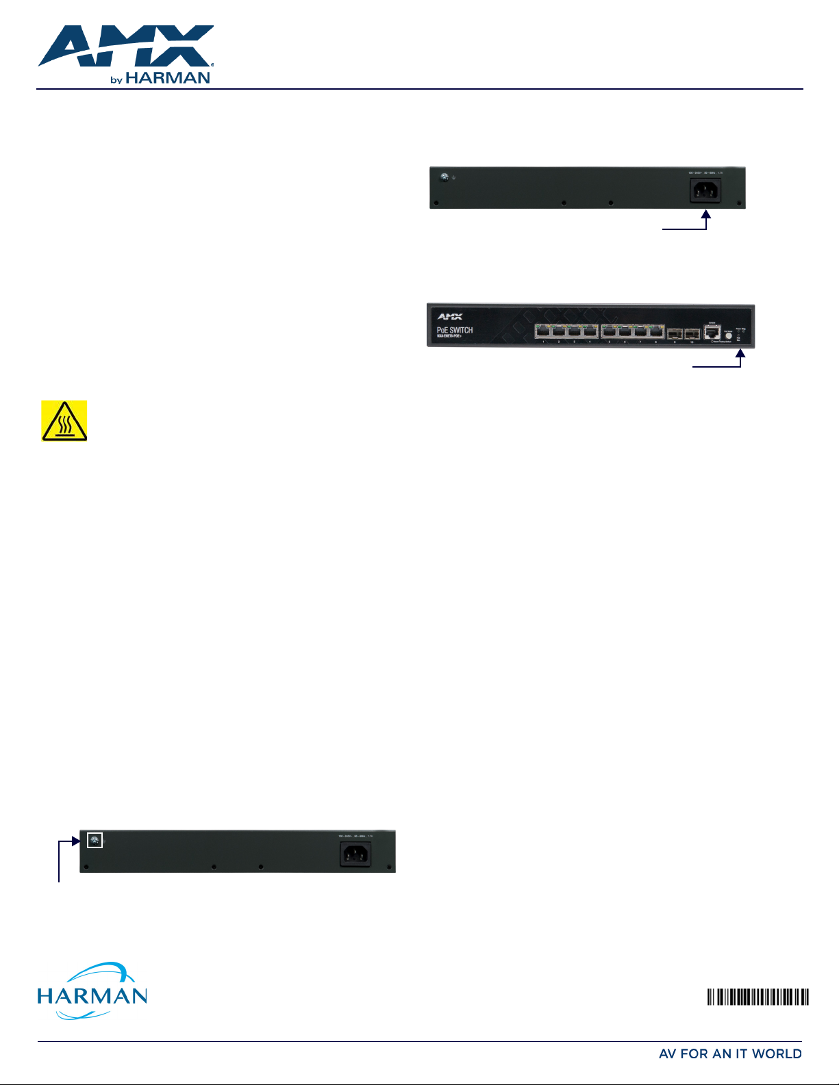
connect grounding wire
connect AC power
System Status LEDs
NXA-ENET8-POE+ Gigabit PoE Ethernet Switch
Overview
This guide pertains to the NXA-ENET8-POE+ Gigabit PoE Ethernet Switch (FG2178-64).
The purpose of this document is to illustrate how the device is to be installed and set up
in its simplest configuration by a trained technician.
Additional Documentation
Additional documentation for this device is available at www.amx.com. Refer to the
NXA-ENET8-POE+ Instruction Manual for additional details on installing, upgrading, and
wiring the NXA-ENET8-POE+.
What’s in the Box?
The following items are included with the NXA-ENET8-POE+:
• NXA-ENET8-POE+ Gigabit PoE Ethernet Switch
• AC Power Cord
• Rack Mounting Kit containing two standard brackets and eight screws for
attaching the brackets to the switch.
• 4 adhesive foot pads for surface mounting
• Quick Start Guide
•Safety Instructions
Chassis Specifications
Size (WxDxH): 12.99 x 8.03 x 1.67 in. (33.0 x 20.4 x 4.26 cm)
Weight: 5.34lb (2.4kg)
WARNING: On the NXA-ENET8-POE+, the bottom o f the enclosure is a
hot surface. Do no t touch!
Environmental Requirements
The environmental requirements for the NXA-ENET8-POE+ are as follows:
• Operating Temperature: 32° F (0° C) to 104° F (40° C)
• Storage Temperature: -40° F (-40° C) to 158° F (70° C)
• Storage H umid ity: 0% to 90% RH (non-condensing)
Rack Mounting the Switch
The switch is designed to be installed in a standard 19-inch rack or on a desktop or
shelf. Following your rack plan, mark the holes in the rack where the switch will be
installed. Lift the switch into the rack and hold it in a position aligned with the marked
holes. Secure the switch in the rack, using four rack-mounting screws (not provided).
CAUTION: For safe operation, install the switch with the RJ-45 ports facing up.
Power
Active power requirements:
• AC Input Power: 100-240V, 50-60Hz, 2.1A
• Total Power consumption: 160W
NOTE: Maximum power consumption values are measured under a 100 percent loading
test and should be used as estimates for planning purposes.
Grounding the Switch
CAUT ION : Th e dev ice must be installed i n a restricted-access location, and the protective
earthing terminal on the chassis must be permanently connected to earth ground to
ground the chassis and protect the operator from electrical hazards.
Before powering on the switch, ground the switch to earth.
Ensure the rack on which the switch is to be mounted is properly grounded and in
compliance with ETSI ETS 300 253. Verify that there is a good electrical connection to
the grounding point on the rack (no paint or isolating surface treatment).
CAUTION: The earth connection must not be removed unless all supply connections have
been disconnected.
Connecting Power
Connect the switch to an AC power source to power on. Verify that the external AC
power requirements for the switch can be met as listed in the Power section above.
CAUTION: Before connecting the switch to AC power, the grounding terminal screw on the
switch rear panel must be connected to earth.
FIG. 2 PLUG THE AC POWER CORD INTO THE SOCKET ON THE REAR OF THE SWITCH
Verifying Switch Operation
Verify basic switch operation by checking the system LEDs.
When operating normally, the Diag and Power LEDs should both be green.
FIG. 3 SYSTEM STATUS LEDS
Making Initial Conf iguration Changes
At this point, you may need to make a few basic switch configuration changes before
connecting to the network. you can either connect to the switch console port or any
RJ-45 port to perform this task.
Through an RJ-45 Port
The switch offers a user-friendly web-based management interface for the
configuration of all the unit’s features.
You can make initial configuration changes by connecting a PC directly to one of the
switch’s RJ -45 ports. The switch has a default management IP address of 192.168.2.10
and a subnet mask of 255.255.255.0. You must set your PC IP address to be on the
same subnet as the switch (that is, the PC and switch addresses must both start
192.168.2.x).
Log in to the web interface using the default settings:
• Login Name: admin
•Password: admin
Through the Console Port
The serial port’s conf iguration requirements are as follows: 115200 bps, 8 characters,
no parity, one stop bit, 8 data bits, and no flow control. You can log in to the
command-line interface (CLI) using default settings:
•User: admin
•Password: admin
Connecting Network Cables
Install SFP transceivers and connect network cables to port interfaces:
• For RJ-45 ports, use 100-ohm Category 5, 5e or better twisted-pair cable for
1000BASE-T connections, Category 5 or better for 100BASE-TX connections, and
Category 3 or better for 10BASE-T connections.
• First install SFP transceivers and then connect fiber optic cabling to the
transceiver ports. As connections are made, check the port status LEDs to be sure
the links are valid.
FIG. 1 CONNECT A GROUNDING WIRE AND LUG TO THE GROUNDING POINT ON THE SWITCH REAR
PANEL, AND THEN TO THE RACK GROUND
© 2016 Harman. All rights reserved. AMX, AV FOR AN IT WORLD, and HARMAN, and their respective logos are registered trademarks of HARMAN.
Oracle, Java and any other company or brand name referenced may be trademarks/registered trademarks of their respective companies.
AMX does not assume responsibility for errors or omissions. AMX also reserves the right to alter specifications without prior no tice at any time.
The AMX Warranty and Return Policy and related documents can be viewed/downloaded at www.amx.com.
3000 RESEARCH DRIVE, RICHARDSON, TX 75082 AMX.com | 800.222.0193 | 469.624.8000 | +1.469.624.7400 | fax 469.624.7153
AMX (UK) LTD, AMX by HARMAN - Unit C, Auster Road, Clifton Moor, York, YO30 4GD United Kingdom • +44 1904-343-100 • www.amx.com/eu/
 Loading...