

Page 1
DATA SHEET
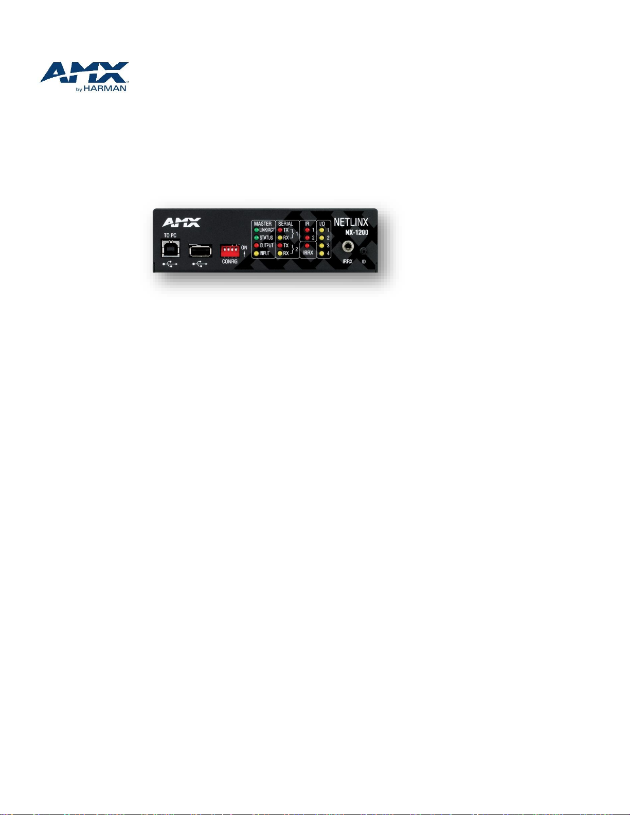
NetLinx
NX-1200 (FG2106-01)
®
NX Integrated Controller
Overview
The NX-1200 / NetLinx® NX Integrated Controller is a programmable network
appliance specifically designed to control AV and building technology using multiple
analog and digital formats. The NX-1200 provides a scalable platform for the future
by combining high performance, backward compatibility and extensive network
security features. The NX-1200 is designed to control and automate a variety of
devices in single rooms or multiple small rooms and is capable of supporting
devices with a variety of communication formats.
Common Applications
The NX-1200 is perfect for small classrooms, huddle spaces, small conference rooms, learning spaces and
multi-zone systems with a small number of wired devices
The NX-1200 is designed to provide secure control and monitoring for a small AV system, HVAC, lights,
security, power management, and many similar specialized applications requiring a space-saving physical
control device with versatile mounting
Features
IPv6 and wired 802.1x – Supports modern networking standards for internet protocol IPv6 and port-based
Network Access Control utilizing X.509 certificates for access to protected networks
High Performance Architecture, Flexible Programming Platform (RPM, NetLinx and Java) – Easily scalable to
support a wide range of applications for today and tomorrow
Full Line Compatible (Backwards and Cross-Compatibility) – Standardized port numbers and new
configuration import/export tools mean fewer coding changes
Enhanced Diagnostics On Serial and IR Ports – Provides real time error feedback when Serial and IR ports are
disconnected or improperly wired
File Import / Export From USB Drive – Backup and restore configuration data, program files, and update
firmware from a standard USB flash drive
Hardware / Software Built for 24/7/365 Operation – Provides outstanding reliability and improved
diagnostics
Ultra-Fast 1600 MIPS processor
512 MB Onboard RAM
1 M Non-Volatile Memory
© 2014 AMX. All rights reserved.
Page 2

2
4 GB SDHC FLASH Memory
GENERAL
Enclosure
Metal with black matte finish
Dimensions (HWD)
1 11/16” x 5 13/16” x 5 1/8” (42.16 mm x 147.32 mm x
130.81 mm)
Weight
1.6 lb. (.726 Kg)
Regulatory Compliance
•FCC CFR Title 47 Part 15
•CE EN 55022
•CE EN 55024
•CE EN 60950-1
•IEC 60950-1
•UL 60950-1
•C-Tick CISPR 22
•IC CISPR 22
•VCCI CISPR 22
•RoHS / WEEE compliant
Included Accessories
•2-pin 3.5 mm mini-Phoenix (female) PWR connector
(41-0002-SA)
•4-pin 3.5 mm mini-Phoenix (female) AxLink connector
(41-5047)
•10-pin 3.5mm mini-Phoenix female RS232/422/485
connectors (41-5107)
•5-pin 3.5mm mini-Phoenix female RS232 connectors
(41-0336)
•6-pin 3.5 mm mini-Phoenix female I/O connector (41-
5063)
•(2) CC-NIRC IR Emitters
Optional Accessories
•AVB-VSTYLE-RMK, V Style Module Rack Mounting Tray, 5
1/4" Depth (FG1010-720)
•AVB-VSTYLE-SURFACE-MNT, V Style Single Module
Surface Mount Brackets (FG1010-722)
•PSN6.5, 6.5 A Power Supply (FG423-41)
•PSR4.4, 13.5 VDC, 4.4 A Power Supply with 3.5 mm
Phoenix Connector with Retention Screws (FG423-46)
•PSN4.4, 13.5 VDC, 4.4 A Power Supply with 3.5 mm
Phoenix Connector (FG423-45)
•CC-USB-NI, USB Programming Cable (FG10-2105)
•CC-NIRC, IR Cables (FG10-000-11)
•CC-NET, Cat5 Ethernet Cable (FG10-051-10)
•CBL-ETH-FL, Ethernet Cat5e Flat Cable (FG10-2182-
16)
•EXB-IRS4, ICSLan IR/S Interface, 4 IR/S and 4 Inputs
(FG2100-23)
•EXB-COM2, ICSLan Serial Interface, 2 Ports (FG2100-
22)
•EXB-REL8, ICSLan Relay Interface, 8 Channels
(FG2100-20)
1 RU x 1/3 Rack Space
1 AXLink Interface
1 10/100 LAN Interface
4 Digital I/O Ports
1 RS232/422/485 Port
1 RS232-Only Port
2 IR/Serial Output Ports
1 IR Receive Port
Specifications
Page 3

3
•EXB-I/O8, ICSLan Input/Output Interface, 8 Channels
(FG2100-21)
•EXB-MP1, ICSLan Multi-Port, 1 COM, 1 IR/S, 2 I/O, 1
IR RX (FG2100-26)
ACTIVE POWER REQUIREMENTS
Voltage, DC (Typical)
12 VDC
DC Current Draw
200 mA @ 12 VDC
Voltage DC Range
9 - 18 VDC
Power Connector
3.5mm Phoenix with retaining screws
POWER CONSUMPTION
Active Power Consumption
3 W
ENVIRONMENTAL
Temperature (Operating)
32° F to 122° F (0° C to 50° C)
Temperature (Storage)
14° F to 140° F (-10° C to 60°C)
Humidity (Operating)
5% to 85% RH
Heat Dissipation (Typical)
10.2 BTU/hr
ONBOARD MASTER
Processor
1600 MIPS
Program Port
(1) USB Standard B
Configuration Dip Switch
4-position
Status Indicator
Status LED (green) blinks to indicate that the system is
programmed and communicating properly
Input Indicator
Input LED (yellow) blinks to indicate that the Controller
is receiving data
Output Indicator
Output LED (red) blinks to indicate that the Controller
is transmitting data
ID Pushbutton
Black ID pushbutton for setting IP mode and reverting
to default configuration and firmware
USB Host Port
(1) USB Standard A, USB Host port supports Solid State
drive for upgrading firmware, loading code files,
copying configuration data and remote storage
MEMORY
NVRAM
1 MB
Memory Card
4 GB SD
DDRAM
512 MB
Note
Supports external USB Solid State Drives (FAT32)
ETHERNET
Connection
(1) RJ-45
Description
10/100 Port RJ-45 connector provides TCP/IP
communication. Auto MDI/MDI-X enabled. Supports
IPv4 and IPv6 networks. Supports HTTP, HTTPS, Telnet,
FTP
Link/Act Indicator
Link/Activity LED (green) blinks when receiving
Ethernet data packets, one on Ethernet RJ-45
connector and one on the front panel
Page 4

4
Speed Indicator
Speed LED (yellow) lights On when the connection
speed is 100 Mbps Ethernet connection and turns OFF
when the speed is 10 Mbps
CONTROL PORTS & INDICATORS
AxLink Port
(1) 4-position 3.5mm Screw Terminal, provides data
and power to external AxLink control devices
AxLink Indicator
(1) AxLink LED (green) indicates the state of the AxLink
port
RS-232/422/485 Port
(1) 10-position 3.5mm Screw Terminal
NetLinx Port 1
XON/XOFF (transmit on / transmit off)
CTS/RTS (clear to send/ready to send)
300 - 115,200 baud
RS-232 Port
(1) 5-position 3.5mm Screw Terminal
NetLinx Port 2
XON/XOFF (transmit on / transmit off)
CTS/RTS (clear to send/ready to send)
300 - 115,200 baud
Serial Indicator
(2) sets of LEDs (red/yellow) indicate when serial Ports
1 and 2 are transmitting and receiving
data
IR/Serial
(2) 2-position 3.5mm Screw Terminal
2 IR Transmit / 1-way Serial ports
NetLinx Ports 11-12
Support high-frequency carriers up to 1.142 MHz
2 IR/Serial data signals can be generated
simultaneously
IR/Serial Indicators
(2) LEDs (red) indicate when each of the IR/Serial
ports (11-12) are transmitting control data
I/O Channels
(4) One 6-position 3.5mm Screw Terminal
4-channel binary I/O port for contact closure with each
input being capable of voltage sensing
NetLinx Port 22
Channels 1-4
I/O Indicator
(4) LEDs (yellow) indicate each of the I/O
channels (1-4) are active
IR/RX Ports
(1) 1/8” mini-jack
TBA
IR/RX Indicator
(1) IR RX LED (red) LED lights when IR data is being
received via the IR/RX port
Page 5

5
For a more detailed pictorial drawing please visit: http://www.amx.com/products/NX-1200.asp
About AMX by HARMAN
Founded in 1982 and acquired by HARMAN in 2014, AMX® is dedicated to providing AV solutions for an IT World. AMX solves the complexity of
managing technology with reliable, consistent and scalable systems comprising control, video switching and distribution, digital signage and technology
management. AMX systems are deployed worldwide in conference rooms, classrooms, network op eration/command centers, homes, hotels,
entertainment venues and broadcast facilities, among others. AMX is part of the HARMAN Professional Group, the only total audio, video, lighting, and
control vendor in the professional AV market. HARMAN designs, manufactures and markets premier audio, video, infotainment and integrated control
solutions for the automotive, consumer and professional markets. Revised 11.12.14. ©2014 Harman. All rights reserved. Specifications subject to
change.
www.amx.com | +1.469.624.7400 |800.222.0193
 Loading...