

Page 1

Operation/Reference Guide
MAX Servers
HT Home Theater and
MMS Multimedia Servers
MAX by AMX
®
Last Revised: 9/10/2007
Page 2

AMX Limited Warranty and Disclaimer
AMX warrants its products to be free of defects in material and workmanship under normal use for three (3) years from
the date of purchase from AMX, with the following exceptions:
• Electroluminescent and LCD Control Panels are warranted for three (3) years, except for the display and touch
overlay components that are warranted for a period of one (1) year.
• Disk drive mechanisms, pan/tilt heads, power supplies, and MX Series products are warranted for a period of one
(1) year.
• AMX Lighting products are guaranteed to switch on and off any load that is properly connected to our lighting
products, as long as the AMX Lighting products are under warranty. AMX does guarantee the control of dimmable
loads that are properly connected to our lighting products. The dimming performance or quality cannot be guaranteed due to the random combinations of dimmers, lamps and ballasts or transformers.
• Unless otherwise specified, OEM and custom products are warranted for a period of one (1) year.
• AMX Software is warranted for a period of ninety (90) days.
• Batteries and incandescent lamps are not covered under the warranty.
This warranty extends only to products purchased directly from AMX or an Authorized AMX Dealer.
All products returned to AMX require a Return Material Authorization (RMA) number. The RMA number is obtained
from the AMX RMA Department. The RMA number must be clearly marked on the outside of each box. The RMA is
valid for a 30-day period. After the 30-day period the RMA will be cancelled. Any shipments received not consistent
with the RMA, or after the RMA is cancelled, will be refused. AMX is not responsible for products returned without a
valid RMA number.
AMX is not liable for any damages caused by its products or for the failure of its products to perform. This includes any
lost profits, lost savings, incidental damages, or consequential damages. AMX is not liable for any claim made by a
third party or by an AMX Dealer for a third party.
This limitation of liability applies whether damages are sought, or a claim is made, under this warranty or as a tort claim
(including negligence and strict product liability), a contract claim, or any other claim. This limitation of liability cannot
be waived or amended by any person. This limitation of liability will be effective even if AMX or an authorized representative of AMX has been advised of the possibility of any such damages. This limitation of liability, however, will not
apply to claims for personal injury.
Some states do not allow a limitation of how long an implied warranty last. Some states do not allow the limitation or
exclusion of incidental or consequential damages for consumer products. In such states, the limitation or exclusion of
the Limited Warranty may not apply. This Limited Warranty gives the owner specific legal rights. The owner may also
have other rights that vary from state to state. The owner is advised to consult applicable state laws for full determination of rights.
EXCEPT AS EXPRESSLY SET FORTH IN THIS WARRANTY, AMX MAKES NO OTHER WARRANTIES,
EXPRESSED OR IMPLIED, INCLUDING ANY IMPLIED WARRANTIES OF MERCHANTABILITY OR FITNESS FOR
A PARTICULAR PURPOSE. AMX EXPRESSLY DISCLAIMS ALL WARRANTIES NOT STATED IN THIS LIMITED
WARRANTY. ANY IMPLIED WARRANTIES THAT MAY BE IMPOSED BY LAW ARE LIMITED TO THE TERMS OF
THIS LIMITED WARRANTY.
Page 3

Table of Contents
Table of Contents
MAX Servers - Overview ....................................................................................1
Related Documents.................................................................................................................. 2
MAX HT Servers - Photos and Specifications ......................................................3
MAX-HT04/HT12 Home Theater Servers ........................................................................ 3
Product Specifications ............................................................................................................. 4
MAX MMS Servers - Photos and Specifications ..................................................7
MMS-01S Multimedia Server ........................................................................................... 7
Product Specifications ............................................................................................................. 7
MMS-02S Multimedia Server ........................................................................................... 9
Product Specifications ........................................................................................................... 9
MMS-02SB Multimedia Server with Backup ................................................................... 11
Product Specifications ........................................................................................................... 11
MMS-04S Multimedia Server ......................................................................................... 13
Product Specifications ......................................................................................................... 13
MMS-12S Multimedia Server ......................................................................................... 15
Product Specifications ........................................................................................................... 15
MMS-900 Multimedia Server........................................................................................... 17
Product Specifications ........................................................................................................... 18
MAX Servers - Setup and Configuration ...........................................................19
Overview ......................................................................................................................... 19
Networking Specifications for MAX Servers.................................................................... 19
Online Database .................................................................................................................... 20
Mandatory 24-Hour Initialization Period (HT Servers only) ............................................. 20
If Power Is Removed From the HT Server ............................................................................. 20
Step 1: Connect a Mouse, Keyboard and VGA Monitor ................................................. 20
Step 2: Connect the Power Cable(s) and Apply Power................................................... 21
MMS-01S, -02S, -02SB and MAX-HT Servers: ..................................................................... 21
MMS-04S and -12S Servers: ................................................................................................. 21
MMS-900 Servers: ................................................................................................................. 21
MAX-HT Servers: ................................................................................................................... 21
Step 3: Access the MAX Admin Menu ............................................................................ 22
Working With the MAX Admin Menu ...................................................................................... 22
Step 4: Add MAX-AVPs and AVM/AOM Modules to the HT Server................................ 22
Adding MAX-AVP Players and/or MAX-AVM Modules .......................................................... 22
Adding MAX-AOM Audio-Only Modules ................................................................................ 23
Additional Information on USB Ports: MMS-01S, -02S and 02SB Servers ............................ 23
MAX Servers: HT Home Theater and MMS Multimedia Servers
i
Page 4

Table of Contents
Additional Information on USB Ports: MMS-04S, -12S, -900 and MAX-HT Servers.............. 24
Step 5: Connect the Modules To the MAX Server .......................................................... 24
Connecting MAX-AVPs and/or MAX-AVMs ........................................................................... 24
Connecting MAX-AOM Modules ............................................................................................ 25
Step 6: Install and Configure WinMAX Software............................................................. 25
If You Don’t Connect .............................................................................................................. 25
Loading Media Content on the MAX Server.................................................................... 26
DVD and CD Playback.................................................................................................... 26
Playing a DVD........................................................................................................................ 26
Playing a CD .......................................................................................................................... 26
Periodic Updates............................................................................................................. 26
Shutting Down the MAX Server ...................................................................................... 26
MAX Admin Menu ............................................................................................27
Overview ......................................................................................................................... 27
Accessing the Admin Menu via WinMAX ............................................................................... 27
Accessing the Admin Menu via Direct Connection to the MAX Server .................................. 28
MAX Admin Menu Options - Overview................................................................................... 28
System Information ........................................................................................................ 29
IP Settings ...................................................................................................................... 30
Preparing the MAX Server for Receiving Periodic Updates................................................... 31
Output Module Setup ..................................................................................................... 31
Adding New Modules to the System ...................................................................................... 32
Viewing all Modules in the System......................................................................................... 33
Removing Modules From the System .................................................................................... 33
RAID 5 Status ................................................................................................................. 33
RAID 5 CLI ...................................................................................................................... 34
Log Management ........................................................................................................... 35
Specifying Logging Levels ..................................................................................................... 35
Viewing Log Files ................................................................................................................... 35
Deleting Log Files .................................................................................................................. 36
Date, Time Locale ........................................................................................................... 36
Setting System Date and Time .............................................................................................. 37
Shell ................................................................................................................................ 38
Modify max.ini ................................................................................................................ 38
Authenticate HDD ........................................................................................................... 39
Authenticating a new HDD ..................................................................................................... 39
Viewing All HDDs In the MAX Server..................................................................................... 40
Removing HDDs From the MAX Server................................................................................. 40
Parental Control ............................................................................................................. 41
ii
MAX Servers: HT Home Theater and MMS Multimedia Servers
Page 5

Table of Contents
Online Tech Support ...................................................................................................... 41
Cover Art ......................................................................................................................... 42
Change Region ............................................................................................................... 42
Changing The Region Code Setting On Your MAX Server.................................................... 43
Update Firmware ............................................................................................................ 43
Scheduling Automatic Firmware Updates .............................................................................. 43
Manually Updating the Firmware ........................................................................................... 44
Restart MAX deamon ...................................................................................................... 44
Shutdown ....................................................................................................................... 44
Exit .................................................................................................................................. 44
Exit and Disconnect......................................................................................................... 44
DVD Region Code Settings ..............................................................................45
Overview ......................................................................................................................... 45
DVD Regions (1-6) .......................................................................................................... 45
Default Region Code Setting........................................................................................... 46
Changing the Region Code Setting on MAX Servers...................................................... 46
Changing the DVD Region Code Setting On MAX Servers ............................................ 47
MAX Servers DVD Drives - Supported Formats ...............................................49
DVD Drives - Compatible Formats .................................................................................. 49
MAX Servers - DVD Drives Used.................................................................................... 49
MDL Series - DVD Drives................................................................................................ 50
Replacing HDDs in MAX Servers ......................................................................51
Overview ......................................................................................................................... 51
Replacing HDDs in MMS Servers ................................................................................... 51
Step 1: Identify the Drive That Needs To Be Replaced ......................................................... 51
Step 2: Physical Removal and Replacement of the Drives ................................................... 54
Step 3: Rebuild the RAID Array ............................................................................................. 54
Step 4: Authenticate the New HDD ........................................................................................ 55
a) Open a telnet session with the MMS server: ..................................................................... 55
b) Authenticate the new HDD:................................................................................................ 55
Replacing HDDs in HT Servers....................................................................................... 56
Step 1: Identify the Drive That Needs To Be Replaced ......................................................... 57
Step 2: Physical Removal and Replacement of the Drives .................................................... 57
Step 3: Add the New Drive to the System.............................................................................. 58
MAX Admin Menu ........................................................................................................... 59
Rack Mounting MAX Servers ............................................................................61
CAUTION: Safety Instructions......................................................................................... 61
Rack Mounting MMS-01S/02S/02SB/04S/12S Servers .................................................. 62
MAX Servers: HT Home Theater and MMS Multimedia Servers
iii
Page 6

Table of Contents
Step 1: Prepare the Slide Rail Assemblies ............................................................................ 63
Step 2: Attach the Inner Server Rails to the MMS chassis .................................................... 63
Step 3: Attach the Extension Brackets to the Outer Rails ...................................................... 63
Step 4: Install the Outer Rail/Extension Racket Assemblies In the Rack............................... 64
Step 5: Load the MMS Server Into the Rack.......................................................................... 64
Rack Mounting HT and MMS-900 Servers ..................................................................... 65
CAUTION: Safety Instructions ........................................................................................ 66
Step 1: Install Chassis Sections Onto The Server Chassis ................................................... 66
Step 2: Slide Intermediate Sections Into the Stationary Sections .......................................... 67
Step 3: Attach the Extension Brackets................................................................................... 68
Step 4: Mount the Adapter Bars to the Rack-Rail assemblies ............................................... 68
Step 5: Mount the Rail/Bracket Assemblies Into the Equipment Rack................................... 69
Step 6: Load the HT Server Into the Rack ............................................................................. 70
iv
MAX Servers: HT Home Theater and MMS Multimedia Servers
Page 7
MAX Servers - Overview
NOTICE: MAX Products are not designed or intended to, and may not be used to, violate anyone’s
copyright or other intellectual property rights. Each user of the Products may only use the Products in
connection with materials legally owned or licensed by such user and only to the extent such ownership
or license rights permit such use.
MAX-MMS (Multimedia) and MAX-HT (Home Theater) Servers utilize robust internal disk drive
systems to keep an ever expanding library of DVDs and CDs well organized, simple to access, and easy
to use. MAX servers allow you to efficiently manage hundreds of DVDs and CDs.
MAX servers accommodate single and multi-room video distribution, allowing the user to search and
select chapters, titles and tracks. Video is stored in native DVD format to fully capture the quality of the
original video. Music is stored in native audio CD format. Additionally, MAX servers provide playback
of MP3 files.
MAX servers support up to 25 MAX-AVM audio/video modules, via Ethernet.
MAX servers support 1 or 2 MAX-AOM audio-only modules (each of which can distribute
four zones of audio), via USB.
MAX Servers - Overview
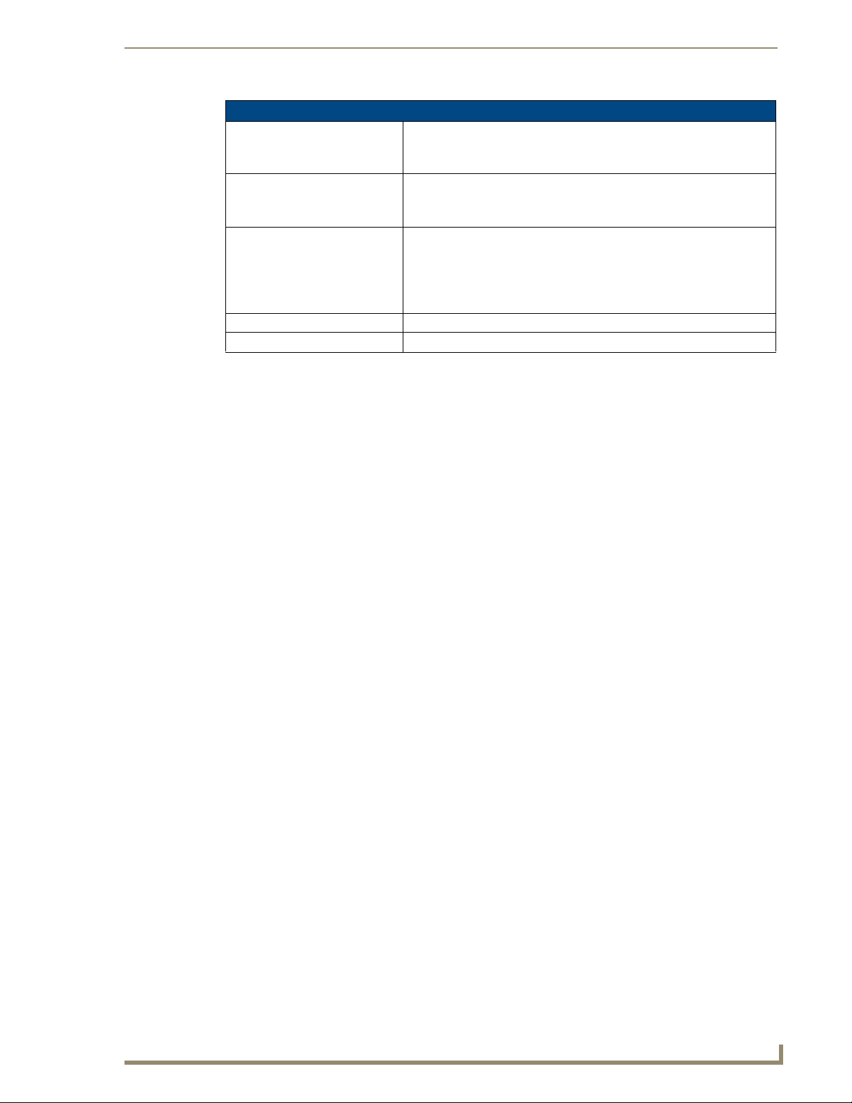
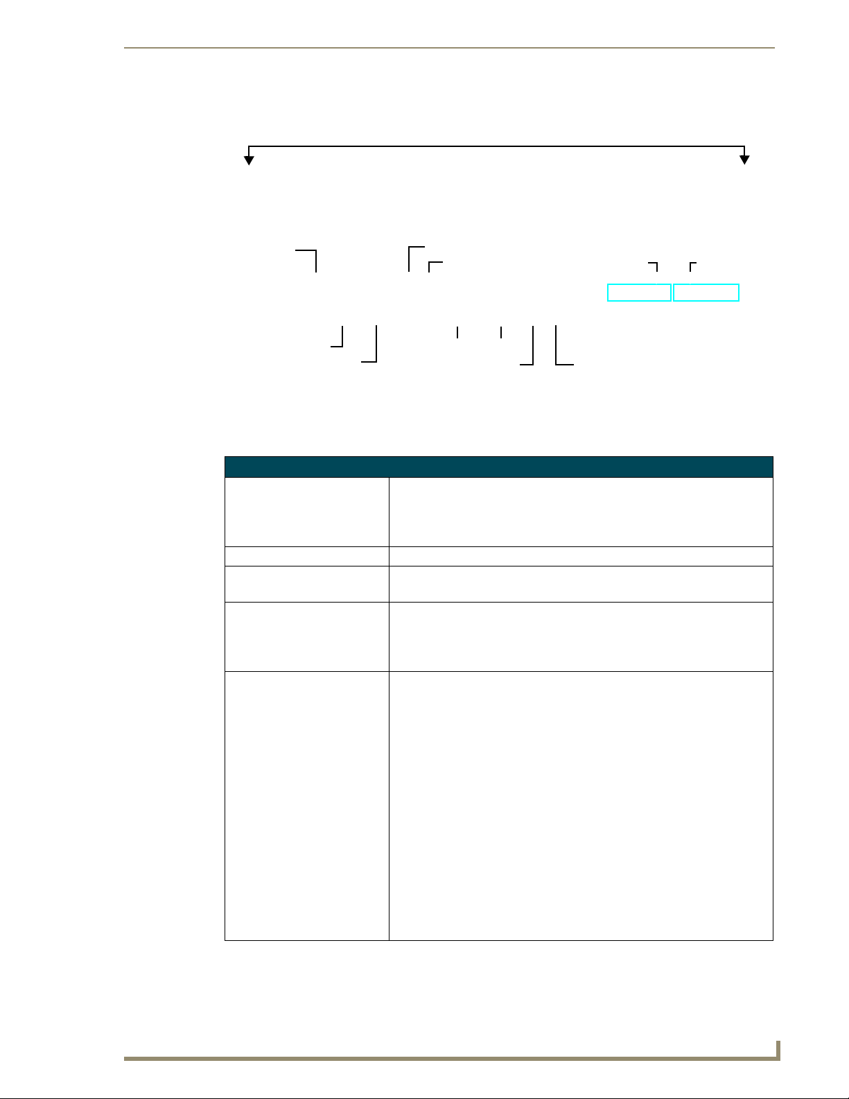
MMS Multimedia Servers
MMS-01S (FG 2178-10)
approximately 250GB of content storage approximately 500GB of content storage
MMS-02SB (FG 2178-11)
approximately 250GB of content storage approximately 1TB of content storage
MMS-12S (FG 2178-08)
approximately 3TB of content storage
FIG. 1 MAX MMS Multimedia Servers
MMS-02S (FG 2178-12)
MMS-04S (FG 2178-07)
MMS-900 (FG 2178-06)
more than 7TB of content storage
Refer to the MAX Modules Instruction Manual (available online at www.amx.com), as
well as the individual Installation Guides for details and installation instructions on
MAX Modules.
MAX Servers: HT Home Theater and MMS Multimedia Servers
1
Page 8
MAX Servers - Overview
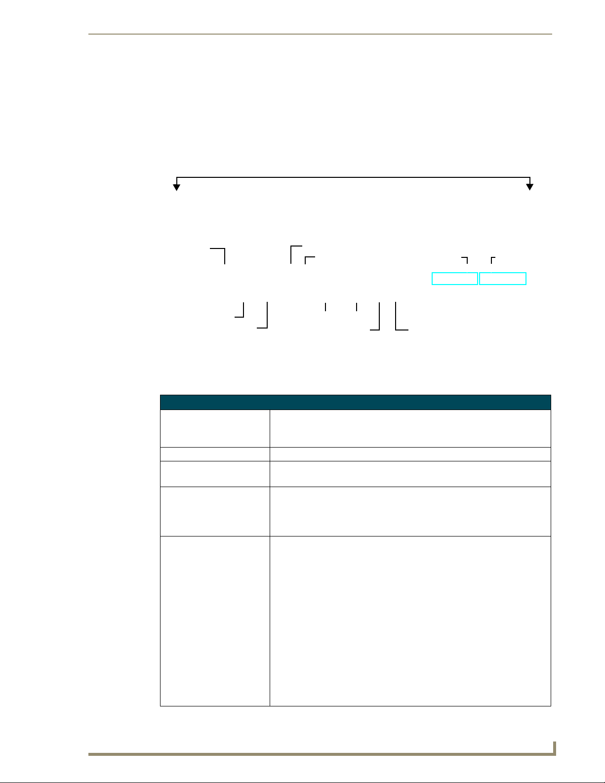
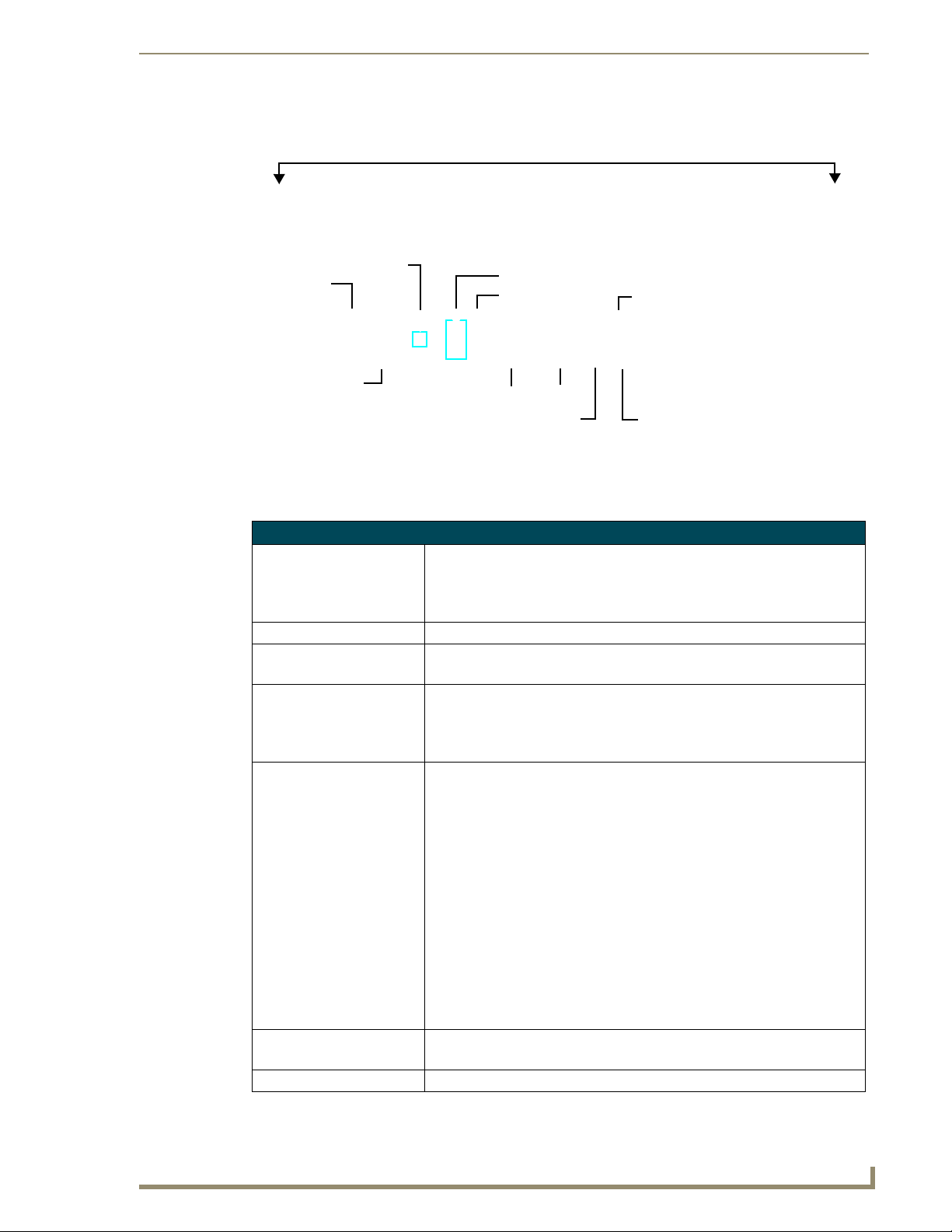
HT Home Theater Servers
MAX-HT04 (FG 2178-14)
more than 1TB of content storage more than 4TB of content storage
FIG. 2 MAX HT Home Theater Servers
Connect a PS/2 mouse and keyboard, and a VGA monitor directly to the MAX server to
MAX-HT12 (FG 2178-15)
access the on-board interface, called the MAX Admin Menu. You’ll use the options in the
Admin Menu to configure communication settings and add/remove MAX-AVM and MAXAOM modules. Refer to the MAX Servers - Setup and Configuration section on page 19 for
details.
Depending on the region in which the MAX Server will be installed and operated, you may
need to change the server DVD-ROMs’ region code setting. Refer to the DVD Region Code
Settings section on page 45 for details.
Use the WinMAX software to configure and control MAX servers as well as manage content
from any Windows PC. Refer to the WinMAX Software Instruction Manual (available online
at www.amx.com) for information and instructions.
Related Documents
The following AMX documents provide additional information on the HT Servers and related devices,
and are available online at www.amx.com:
Use the WinMAX software to add/remove DVD/CD content on the server, and control
playback. Refer to the WinMAX Software Instruction Manual for details.
Refer to the MDL-200 Multi-Disc Loader System Instruction Manual for details on using the
MDL200 to bulk-load large numbers of discs to the server.
Refer to the MAX-AOM, MAX-AVM and MAX-AVP Installation Guides and Instruction
Manuals for detailed product information.
2
MAX Servers: HT Home Theater and MMS Multimedia Servers
Page 9
MAX HT Servers - Photos and Specifications
MAX HT Servers - Photos and Specifications
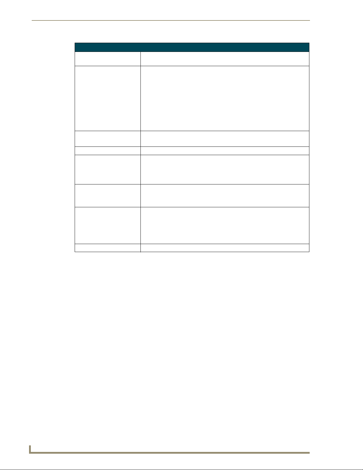
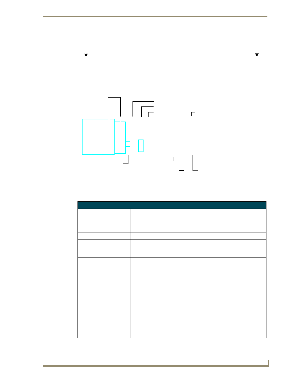
MAX-HT04/HT12 Home Theater Servers
DVD/CDRW tray
Storage Disc Drives
Power ON/OFF toggle switch
Master
Powe r
switch
FIG. 3 MAX-HT04/12 Home Theater Servers
Powe r
cable
connector
RS-232 VGA
USB 2 port
PS/2 keyboard
& mouse ports
IMPORTANT! MAX-HT Servers require a 24-hour initialization period. This simply
entails powering up the server and letting it charge and initiate for 24 hours before
use. Failure to allow this initialization to complete may cause performance problems
during media playback.
MAX Servers: HT Home Theater and MMS Multimedia Servers
USB 1 port
ETHERNET CONTROL
switched GB Control segment
(to NetLinx Master or PC)
A/V OUT
switched GB Content segment
(to MAX-AVMs and/or MAX-AVPs)
3
Page 10
MAX HT Servers - Photos and Specifications
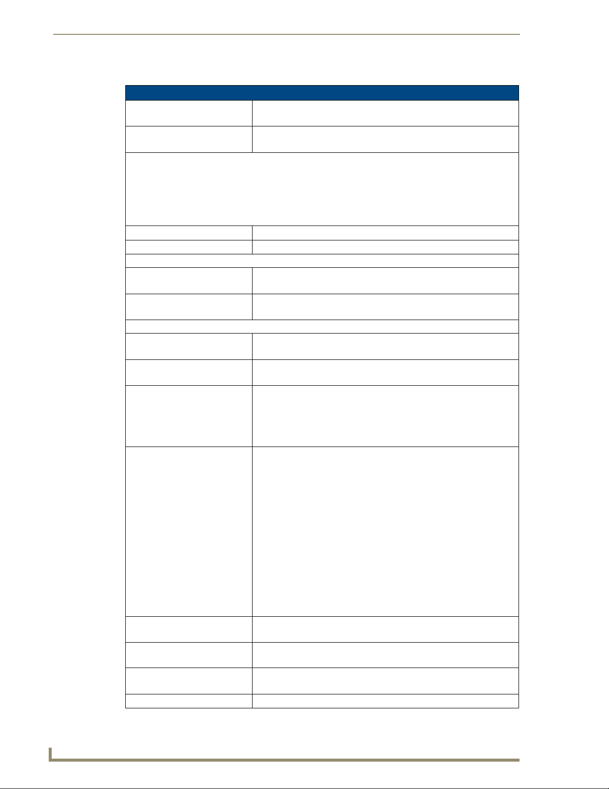
Product Specifications
MAX-HT04/HT12 Specifications
Device Models: • MAX-HT04 (FG 2178-14)
Storage Capacity: • MAX-HT04: 1.1 TBs, 275 DVDs (max) / 138 DVDs (min.)
Notes:
• The MAX number of DVDs is based on DVDs at 4.0 GB.
• The MIN number is based on the largest DVD at 8.0 GB.
• DVD capacity is based on typical commercial DVDs.
• DVD size is based on total DVD image, not the length of the movie.
The actual server capacity will vary depending on specific mix of DVDs and CDs in the library.
Disc Management RAID 5 disc drive system
Power: 110-240 VAC +/- 10%, 50/60Hz
AC Current Draw - MAX-HT04:
120 VAC: • Bootup/Power Cycle Peak - 3.0A @ 120V = 360 watts
240 VAC: • Bootup/Power Cycle Peak - 1.5A @ 240V = 360 watts
AC Current Draw - MAX-HT12:
120 VAC: • Bootup/Power Cycle Peak - 6.0A @ 120V = 720 watts
240 VAC: • Bootup/Power Cycle Peak - 3.0A @ 240V = 720 watts
Front Panel Components:
(remove Faceplate to access)
Rear Panel Components: • Power Cable connector: IEC connector for AC power cable (included)
Dimensions (HWD):
(without rack ears)
Weight (servers only): • MAX-HT04: 60 lbs (27.22 kg)
Shipping Weight (including
mounting equipment and box)
• MAX-HT12 (FG 2178-15)
• MAX-HT12: 4.0 TBs, 1000 DVDs (max) / 500 DVDs (min.)
• Normal Usage Peak - 1.9A @ 120V = 228 watts
• Normal Usage Peak - 0.95A @ 240V = 228 watts
• Normal Usage Peak - 3.0A @ 120V = 360 watts
• Normal Usage Peak - 1.5A @ 240V = 360 watts
• MAX-HT04: 4 hot-swappable 400GB hard drives
• MAX-HT12: 12 hot-swappable 400GB hard drives
• DVD/CDRW drive
• Drive Status LEDs
• Ventilated front cover
• Master Power Supply switch: Turns the power supply on/off
• Power On/Off toggle switch: Turns the MAX-HT on/off
• PS/2 Keyboard and Mouse ports (for diagnostics only)
• USB ports 1 & 2: Type A USB connectors connect to MAX-AOM
module(s) for audio distribution
• RS-232 port: (for diagnostics only)
• VGA port: (for diagnostics only)
• ETHERNET CONTROL port: RJ-45 Gigabit Ethernet port provides 1000/
100/10 Mb/s network connectivity between the MAX-HT and the NetLinx
Master or PC
• A/V OUT port: RJ-45 Gigabit Ethernet port provides
1000/100/10 Mb/s network connectivity between the MAX-HT and MAXAVP Audio-Video Players and/or MAX-AVM module(s) for A/V
distribution
• 8.75" x 16.95" x 18.90" (22.23 cm x 43.50 cm x 48.00 cm)
• 5 RU (mounts in a standard 19” equipment rack)
• MAX-HT12: 68 lbs (30.84 kg)
• MAX-HT04: 83.9 lbs (38.06 kg)
• MAX-HT12: 91.9 lbs (41.69 kg)
•
4
MAX Servers: HT Home Theater and MMS Multimedia Servers
Page 11
MAX HT Servers - Photos and Specifications
MAX-HT04/HT12 Specifications (Cont.)
Operating Environment: • Operating Temperature: 10º to 35º C
• Operating Relative Humidity: 20% to 80% (non-condensing)
• Minimum Ventilation Clearance: 3" front and 3" rear
Included Accessories: • One 6’ (1.83m) power cable
• One DVD, one CD
• Rack-Mounting Kit/Installation Guide
Other AMX/MAX Equipment: • MAX-AVP Audio-Video Player (FG 2178-51)
• MAX-AVM Audio-Video Module (FG 2178-50)
• MAX-AOM Audio-Only (USB) Module (FG 2178-55)
• MAX-AOM-EX Expansion Kit (FG 2178-56)
• MAX-MDL200 Multi-Disc Loader (FG 2179-01)
Certifications: UL Listed E252362, FCC, CE
Required Firmware version: 4.30.23 or greater - contact AMX Technical Support for details
MAX Servers: HT Home Theater and MMS Multimedia Servers
5
Page 12

MAX HT Servers - Photos and Specifications
6
MAX Servers: HT Home Theater and MMS Multimedia Servers
Page 13
MAX MMS Servers - Photos and Specifications
MAX MMS Servers - Photos and
Specifications
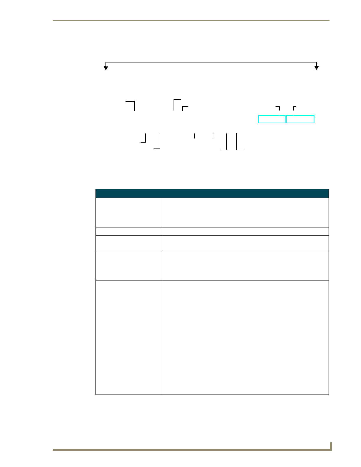
MMS-01S Multimedia Server
Faceplate snaps on/off to allow access to the hard drive and DVD/CDRW drive
Power cable
connector
Master Power switch
Power On/Off
switched GB Content segment
FIG. 4 MMS-01S Multimedia Server
PS/2 keyboard & mouse ports
USB port
RS-232 VGA
A/V OUT
(to MAX-AVM Modules)
(Digital + Analog L/R)
Audio Out 1
ETHERNET CONTROL
switched GB Control segment
(to NetLinx Master or PC)
Audio Out 2
Product Specifications
MMS-01S (FG 2178-10)
Storage capacity: • 250 gigabytes of storage space
• 25 DVD (625 CD) capacity (approximate values)
• Approximately 25 CDs can be stored in place of 1 DVD
Power: 110-240 VAC, 50/60Hz
AC Current Draw (AMP): • 1.01A - Bootup/Power Cycle Peak
• .95A - Normal Usage Peak
Front Panel Components:
(remove Faceplate to access)
Rear Panel Components: • Power Cable connector: IEC connector for AC power cable (included)
• 1 cold-swappable 250GB hard drive
• Drive Status LEDs
•DVD/CDRW drive
• Ventilated front cover
• Master Power Supply switch: Turns the power supply on/off
• Power On/Off button: Turns the MMS on/off
• PS/2 Keyboard and Mouse ports
• USB port: Type A USB connector connects to one MAX-AOM module for
additional audio distribution
• RS-232 port: DB-9 serial port for external control
• Parallel port: not used
• VGA port: DB15HD port provides VGA output
• ETHERNET CONTROL port: RJ-45 Gigabit Ethernet port provides
1000/100/10 Mb/s network connectivity between the MMS and the NetLinx
Master or PC
• A/V OUT port: RJ-45 Gigabit Ethernet port provides 1000/100/10 Mb/s
network connectivity between the MMS and MAX-AVM module(s) for A/V
distribution
(front)
(rear)
MAX Servers: HT Home Theater and MMS Multimedia Servers
7
Page 14
MAX MMS Servers - Photos and Specifications
MMS-01S (FG 2178-10) Product Specifications (Cont.)
Rear Panel Components
(Cont.):
Audio Output: • 2 audio output channels, each with RCA SPDIF digital, analog stereo
Dimensions (HWD):
(without rack ears)
Weight: 26.40 lbs (11.97 kg)
Operating Environment: • Operating Temperature: 10º to 35º C
Included Accessories: • One 6’ (1.83m) power cable
Other AMX/MAX Products: • MAX-AVM Audio-Video Module (FG 2178-50)
Certifications: UL Listed E252362, FCC, CE
• Audio outputs: Two sets of three RCA jacks (D,L,R) provide digital (D) and
analog stereo (L, R) output
• Digital audio output: 6-channel Dolby Digital and DTS
• Analog audio output: stereo
• 24-bit D/A conversion, 128X over sampling
• 48kHz sampling rate
• Output level -10dBV nominal
• Signal to Noise Ratio 110db A-weighted
• Frequency Response: 20Hz to 20kHz
• Dynamic Range: 110dB
• 1.75”" x 17.3" x 20" (4.45 cm x 43.94 cm x 50.80 cm)
• 1 RU (mounts in a standard 19” equipment rack)
• Operating Relative Humidity: 20% to 80% (non-condensing)
• Minimum Ventilation Clearance: 3" front and 3" rear
• Operating acoustic noise: 62 dBA
• One DVD, one CD
• Rack-mounting kit
• MAX-AOM Audio-Only (USB) Module (FG 2178-55)
• MAX-AOM-EX Expansion Kit (FG 2178-56)
• MAX-MDL200 Multi-Disc Loader (FG 2179-01)
• MMS-HDD250G Replacement 250MB HDD (FG 2178-250)
8
MAX Servers: HT Home Theater and MMS Multimedia Servers
Page 15
MMS-02S Multimedia Server
Faceplate snaps on/off to allow access to the hard drive and DVD/CDRW drive
MAX MMS Servers - Photos and Specifications
Powe r cable
connector
Master Power switch
Powe r On /Off
switched GB Content segment
FIG. 5 MMS-02S Multimedia Server
PS/2 keyboard & mouse ports
USB port
RS-232 VGA
A/V OUT
(to MAX-AVM Modules)
(Digital + Analog L/R)
Audio Out 1
ETHERNET CONTROL
switched GB Control segment
(to NetLinx Master or PC)
Audio Out 2
Product Specifications
MMS-02S (FG 2178-12)
Storage capacity: • 500 gigabytes of storage space
• 50 DVD (1,250 CD) capacity (approximate values)
• Approximately 25 CDs can be stored in place of 1 DVD
• Uses a RAID 0 disc drive system
Power: 110-240 VAC, 50/60Hz
AC Current Draw (AMP): • 1.51A - Bootup/Power Cycle Peak
• 1.05A - Normal Usage Peak
Front Panel Components:
(remove Faceplate to access)
Rear Panel Components: • Power Cable connector: IEC connector for AC power cable (included)
• 2 cold-swappable 250GB hard drives
• Drive Status LEDs
•DVD/CDRW drive
• Ventilated front cover
• Master Power Supply switch: Turns the power supply on/off
• Power On/Off button: Turns the MMS on/off
• PS/2 Keyboard and Mouse ports
• USB port: Type A USB connector connects to one MAX-AOM module for
additional audio distribution
• RS-232 port: DB-9 serial port for external control
• Parallel port: not used
• VGA port: DB15HD port provides VGA output
• ETHERNET CONTROL port: RJ-45 Gigabit Ethernet port provides
1000/100/10 Mb/s network connectivity between the MMS and the NetLinx
Master or PC
• A/V OUT port: RJ-45 Gigabit Ethernet port provides 1000/100/10 Mb/s
network connectivity between the MMS and MAX-AVM module(s) for A/V
distribution
• Audio outputs: Two sets of three RCA jacks (D,L,R) provide digital (D) and
analog stereo (L, R) output
(front)
(rear)
MAX Servers: HT Home Theater and MMS Multimedia Servers
9
Page 16

MAX MMS Servers - Photos and Specifications
MMS-02S (FG 2178-12) Product Specifications (Cont.)
Audio Output: • 2 audio output channels, each with RCA SPDIF digital, analog stereo
Dimensions (HWD):
(without rack ears)
Weight: 28 lbs (12.70 kg)
Operating Environment: • Operating Temperature: 10º to 35º C
Included Accessories: • One 6’ (1.83m) power cable
Other AMX/MAX Products: • MAX-AVM Audio-Video Module (FG 2178-50)
Certifications: UL Listed E252362, FCC, CE
• Digital audio output: 6-channel Dolby Digital and DTS
• Analog audio output: stereo
• 24-bit D/A conversion, 128X over sampling
• 48kHz sampling rate
• Output level -10dBV nominal
• Signal to Noise Ratio 110db A-weighted
• Frequency Response: 20Hz to 20kHz
• Dynamic Range: 110dB
• 1.75”" x 17.3" x 20" (4.45 cm x 43.94 cm x 50.80 cm)
• 1 RU (mounts in a standard 19” equipment rack)
• Operating Relative Humidity: 20% to 80% (non-condensing)
• Minimum Ventilation Clearance: 3" front and 3" rear
• Operating acoustic noise: 62 dBA
• One DVD, one CD
• Rack-mounting kit
• MAX-AOM Audio-Only (USB) Module (FG 2178-55)
• MAX-AOM-EX Expansion Kit (FG 2178-56)
• MAX-MDL200 Multi-Disc Loader (FG 2179-01)
• MMS-HDD250G Replacement 250MB HDD (FG 2178-250)
10
MAX Servers: HT Home Theater and MMS Multimedia Servers
Page 17
MAX MMS Servers - Photos and Specifications
MMS-02SB Multimedia Server with Backup
Faceplate snaps on/off to allow access to the hard drive and DVD/CDRW drive
Powe r cable
connector
Master Power switch
Powe r On /Off
switched GB Content segment
FIG. 6 MMS-02SB Multimedia Server with Backup
PS/2 keyboard & mouse ports
USB port
RS-232 VGA
A/V OUT
(to MAX-AVM Modules)
(Digital + Analog L/R)
Audio Out 1
ETHERNET CONTROL
switched GB Control segment
(to NetLinx Master or PC)
Product Specifications
MMS-02SB (FG 2178-11)
Storage capacity: • 250 gigabytes of storage space
• 25 DVD (625 CD) capacity (approximate values) - plus full content backup
• Approximately 25 CDs can be stored in place of 1 DVD
• RAID 1 disc mirroring
Power: 110-240 VAC, 50/60Hz
AC Current Draw (AMP): • 1.49A - Bootup/Power Cycle Peak
• 1.05A - Normal Usage Peak
Front Panel Components:
(remove Faceplate to access)
Rear Panel Components: • Master Power Supply switch: Turns the power supply on/off
• 2 cold-swappable 250GB hard drives
• Drive Status LEDs
• DVD/CDRW drive
• Ventilated front cover
• Power On/Off button: Turns the MMS on/off
• PS/2 Keyboard and Mouse ports
• USB port: Type A USB connector connects to one MAX-AOM module for
additional audio distribution
• RS-232 port: DB-9 serial port for external control
• Parallel port: not used
• Power Cable connector: IEC connector for AC power cable (included)
• VGA port: DB15HD port provides VGA output
• ETHERNET CONTROL port: RJ-45 Gigabit Ethernet port provides
1000/100/10 Mb/s network connectivity between the MMS and the NetLinx
Master or PC
• A/V OUT port: RJ-45 Gigabit Ethernet port provides 1000/100/10 Mb/s
network connectivity between the MMS and MAX-AVM module(s) for A/V
distribution
• Audio outputs: Two sets of three RCA jacks (D,L,R) provide digital (D) and
analog stereo (L, R) output
(front)
Audio Out 2
(rear)
MAX Servers: HT Home Theater and MMS Multimedia Servers
11
Page 18

MAX MMS Servers - Photos and Specifications
MMS-02SB (FG 2178-11) Product Specifications (Cont.)
Audio Output: • 2 audio output channels, each with RCA SPDIF digital, analog stereo
Dimensions (HWD):
(without rack ears)
Weight: 28 lbs (12.70 kg)
Operating Environment: • Operating Temperature: 10º to 35º C
Included Accessories: • One 6’ (1.83m) power cable
Other AMX/MAX Products: • MAX-AVM Audio-Video Module (FG 2178-50)
Certifications: UL Listed E252362, FCC, CE
• Digital audio output: 6-channel Dolby Digital and DTS
• Analog audio output: stereo
• 24-bit D/A conversion, 128X over sampling
• 48kHz sampling rate
• Output level -10dBV nominal
• Signal to Noise Ratio 110db A-weighted
• Frequency Response: 20Hz to 20kHz
• Dynamic Range: 110dB
• 1.75”" x 17.3" x 20" (4.45 cm x 43.94 cm x 50.80 cm)
• 1 RU (mounts in a standard 19” equipment rack)
• Operating Relative Humidity: 20% to 80% (non-condensing)
• Minimum Ventilation Clearance: 3" front and 3" rear
• Operating acoustic noise: 62 dBA
• One DVD, one CD
• Rack-mounting kit
• MAX-AOM Audio-Only (USB) Module (FG 2178-55)
• MAX-AOM-EX Expansion Kit (FG 2178-56)
• MAX-MDL200 Multi-Disc Loader (FG 2179-01)
• MMS-HDD250G Replacement 250MB HDD (FG 2178-250)
12
MAX Servers: HT Home Theater and MMS Multimedia Servers
Page 19
MMS-04S Multimedia Server
Faceplate snaps on/off to allow access to the hard drive and DVD/CDRW drive
MAX MMS Servers - Photos and Specifications
Power On/Off pushbutton
Powe r cable
connector
Master Power
switch
switched GB Content segment
(to MAX-AVM Modules)
FIG. 7 MMS-04S Multimedia Server
PS/2 keyboard & mouse ports
USB 2 port
RS-232 VGA
A/V OUT
USB 1 port
ETHERNET CONTROL
switched GB Control segment
(to NetLinx Master or PC)
Product Specifications
MMS-04S (FG 2178-07)
Storage capacity: • 1 terabyte of storage space
• 100 DVD (2,500 CD) capacity (approximate values)
• Approximately 25 CDs can be stored in place of 1 DVD
• Uses a RAID 5 disc drive system
Power: 110-240 VAC, 50/60Hz
AC Current Draw (AMP): • 1.55A - Bootup/Power Cycle Peak
• 1.15A - Normal Usage Peak
Front Panel Components:
(remove Faceplate to access)
Rear Panel Components: • Power Cable connector: IEC connector for AC power cable (included)
Dimensions (HWD):
(without rack ears)
Weight: 42 lbs (19.05 kg)
• 4 hot-swappable 250GB hard drives
•DVD/CDRW drive
• Drive Status LEDs
• Ventilated front cover
• Master Power Supply switch: Turns the power supply on/off
• Power On/Off button: Turns the MMS on/off
• PS/2 Keyboard and Mouse ports
• USB ports 1 & 2: Type A USB connectors connect to MAX-AOM module(s)
for audio distribution
• RS-232 port: DB-9 serial port for external control
• Parallel port: not used
• VGA port: DB15HD port provides VGA output
• ETHERNET CONTROL port: RJ-45 Gigabit Ethernet port provides
1000/100/10 Mb/s network connectivity between the MMS and the NetLinx
Master or PC
• A/V OUT port: RJ-45 Gigabit Ethernet port provides 1000/100/10 Mb/s
network connectivity between the MMS and MAX-AVM module(s) for
A/V distribution
• 1.75”" x 17.3" x 20" (4.45 cm x 43.94 cm x 50.80 cm)
• 1 RU (mounts in a standard 19” equipment rack)
(front)
(rear)
MAX Servers: HT Home Theater and MMS Multimedia Servers
13
Page 20
MAX MMS Servers - Photos and Specifications
MMS-04S (FG 2178-07) Product Specifications (Cont.)
Operating Environment: • Operating Temperature: 10º to 35º C
Included Accessories: • One 6’ (1.83m) power cable
Other AMX/MAX Products: • MAX-AVM Audio-Video Module (FG 2178-50)
Certifications: UL Listed E252362, FCC, CE
• Operating Relative Humidity: 20% to 80% (non-condensing)
• Minimum Ventilation Clearance: 3" front and 3" rear
• Operating acoustic noise: 62 dBA
• One DVD, one CD
• Rack-mounting kit
• MAX-AOM Audio-Only (USB) Module (FG 2178-55)
• MAX-AOM-EX Expansion Kit (FG 2178-56)
• MAX-MDL200 Multi-Disc Loader (FG 2179-01)
• MMS-HDD250G Replacement 250MB HDD (FG 2178-250)
14
MAX Servers: HT Home Theater and MMS Multimedia Servers
Page 21
MMS-12S Multimedia Server
Faceplate snaps on/off to allow access to the hard drives
MAX MMS Servers - Photos and Specifications
2 Power cable
connectors
2 Removable
power supplies
Power On/Off
switched GB Content segment
(to MAX-AVM Modules)
FIG. 8 MMS-12S Multimedia Server
Power Supply Reset
PS/2 keyboard & mouse ports
USB 2 port
RS-232 VGA
A/V OUT
Product Specifications
MMS-12S (FG 2178-08) Product Specifications
Storage capacity: • 3 terabytes of storage space
• 300 DVD (7,500 CD) capacity (approximate values)
• Approximately 25 CDs can be stored in place of 1 DVD
• Uses a RAID 5 disc drive system
Power: 110-240 VAC, 50/60Hz
AC Current Draw (AMP): For each of the 2 power supplies:
• 3.40A - Bootup/Power Cycle Peak
• 2.06A - Normal Usage Peak
Front Panel Components:
(remove Faceplate to access)
Rear Panel Components: • Two Removable Power Supplies
• 12 hot-swappable 250GB hard drives
• Drive Status LEDs
• Ventilated front cover
• Two Power Cable connectors: IEC connectors for AC power cables
(included)
• Power On/Off button: Turns the MMS on/off
• Power Supply Reset button
• PS/2 Keyboard and Mouse ports
• USB ports 1 & 2: Type A USB connectors connect to MAX-AOM module(s)
for audio distribution
• RS-232 port: DB-9 serial port for external control
• Parallel port: not used
• VGA port: DB15HD port provides VGA output
USB 1 port
ETHERNET CONTROL
switched GB Control segment
(to NetLinx Master or PC)
(front)
(rear)
MAX Servers: HT Home Theater and MMS Multimedia Servers
15
Page 22
MAX MMS Servers - Photos and Specifications
MMS-12S (FG 2178-08) Product Specifications (Cont.)
Rear Panel Components
(Cont.):
Dimensions (HWD):
(without rack ears)
Weight: 64.10 lbs (29.7 kg)
Operating Environment: • Operating Temperature: 10º to 35º C
Included Accessories: • Two 6’ (1.83m) power cables
Other AMX/MAX Products: • MAX-AVM Audio-Video Module (FG 2178-50)
Certifications: UL Listed E252362, FCC, CE
• ETHERNET CONTROL port: RJ-45 Gigabit Ethernet port provides
1000/100/10 Mb/s network connectivity between the MMS and the NetLinx
Master or PC
• A/V OUT port: RJ-45 Gigabit Ethernet port provides 1000/100/10 Mb/s
network connectivity between the MMS and MAX-AVM module(s) for A/V
distribution
• 3.50”" x 17.3" x 20" (8.89 cm x 43.94 cm x 50.80 cm)
• 2 RU (mounts in a standard 19” equipment rack)
• Operating Relative Humidity: 20% to 80% (non-condensing)
• Minimum Ventilation Clearance: 3" front and 3" rear
• Operating acoustic noise: 62 dBA
• One DVD, one CD
• Rack-mounting kit
• MAX-AOM Audio-Only (USB) Module (FG 2178-55)
• MAX-AOM-EX Expansion Kit (FG 2178-56)
• MAX-MDL200 Multi-Disc Loader (FG 2179-01)
• MMS-HDD250G Replacement 250MB HDD (FG 2178-250)
16
MAX Servers: HT Home Theater and MMS Multimedia Servers
Page 23
MMS-900 Multimedia Server
MAX MMS Servers - Photos and Specifications
Storage Disc Drives
DVD/CDRW tray
PS/2 keyboard &
mouse ports
activity LEDs
USB 1 port
USB 2 port
Hard drive
Reset button
Power LED (green)
Bootup Disc LED (yellow)
Fan LED (red)
Power button
ETHERNET CONTROL
switched GB Control segment
(to NetLinx Master or PC)
A/V OUT
switched GB Content segment
(to MAX-AVM Modules)
(front)
(rear)
FIG. 9 MMS-900 Multimedia Server
MAX Servers: HT Home Theater and MMS Multimedia Servers
VGARS-232
4 Power cable connectors
17
Page 24
MAX MMS Servers - Photos and Specifications
Product Specifications
MMS-900 (FG 2178-06)
Storage capacity: • Over 7 terabytes of storage space
Power: • 115 VAC/950W
AC Current Draw (AMP): For each of the 3 power supplies:
Front Panel Components:
(remove Faceplate to access)
Rear Panel Components: • PS/2 Keyboard and Mouse ports
Dimensions (HWD): • 8 11/16" x 18 7/8" x 27 5/8" (22 cm x 47.94 cm x 70.16 cm)
Weight: 120 lbs (54.43 kg)
Operating Environment: • Operating Temperature: 10º to 35º C
Included Accessories: • Four 6’ (1.83m) power cables
Other AMX/MAX Products: • MAX-AVM Audio-Video Module (FG 2178-50)
• 900 DVD (22,500 CD) capacity (approximate values)
• Approximately 25 CDs can be stored in place of 1 DVD
• Uses a RAID 5 disc drive system
• 3+1 redundant power supply
• 350W per module
• 8.84A - Bootup/Power Cycle Peak
• 3.23A - Normal Usage Peak
• DVD/CDRW tray
• 3.5” Floppy disk drive
• Hard Drive LEDs: Bank of LEDs indicate activity on the storage drives
• USB ports: not used
• Fan LED (red): lights to indicate failure of cooling fan(s)
• Bootup Disc LED (yellow): lights to indicate activity on the bootup drive
• Power LED (green): lights to indicate that the unit is on
• Reset button
• Power button
• Removable Hard Drives: 24 hot-swappable 300GB disc drives for storage
• USB ports 1 & 2: Type A USB connectors connect to MAX-AOM module(s) for
audio distribution
• RS-232 port: DB-9 serial port for external control
• VGA port: DB15HD port provides VGA output
• Parallel port: not used
• ETHERNET CONTROL port: RJ-45 Gigabit Ethernet port provides
1000/100/10 Mb/s network connectivity between the MMS and the NetLinx
Master or PC
• A/V OUT port: RJ-45 Gigabit Ethernet port provides 1000/100/10 Mb/s
network connectivity between the MMS and MAX-AVM module(s) for
A/V distribution
• Power connectors: 4 IEC connectors for AC power cables (included)
• 5 RUs (mounts in a standard 19” equipment rack)
• Operating Relative Humidity: 20% to 80% (non-condensing)
• Minimum Ventilation Clearance: 3" front and 3" rear
• One DVD, one CD
• Rack-mounting kit
• MAX-AOM Audio-Only (USB) Module (FG 2178-55)
• MAX-AOM-EX Expansion Kit (FG 2178-56)
• MAX-MDL200 Multi-Disc Loader (FG 2179-01)
• MMS-HDD250G Replacement 250MB HDD (FG 2178-250)
18
MAX Servers: HT Home Theater and MMS Multimedia Servers
Page 25

MAX Servers - Setup and Configuration
MAX Servers - Setup and Configuration
Overview
The following sections describe the basic process of setting up a MAX server and making the
configurations required to get the server up and running with one or more MAX-AVP Audio/Video
Players and/or MAX-AVM Audio/Video Modules and MAX-AOM Audio-Only (USB) modules.
MAX-MMS Servers support up to 25 MAX-AVM modules and up to 2 MAX-AOM (USB)
modules.
MAX-HT Servers support the AVM and AOM modules as well as MAX-AVP Audio/Video
Players. Since the HT Servers treat AVPs exactly the same as AVMs, each HT server supports
up to a total of 25 AVPs/AVMs.
Use the WinMAX software to add/remove content on the MAX server, as well as
control playback and configure the server. Additional documentation, including the
WinMAX Software Instruction Manual and the MAX by AMX Reference Guide are
available online at www.amx.com.
These steps apply to all MAX servers, unless otherwise noted.
Refer to the Product Specifications section for each server to establish the location
and orientation of the connectors mentioned in these steps.
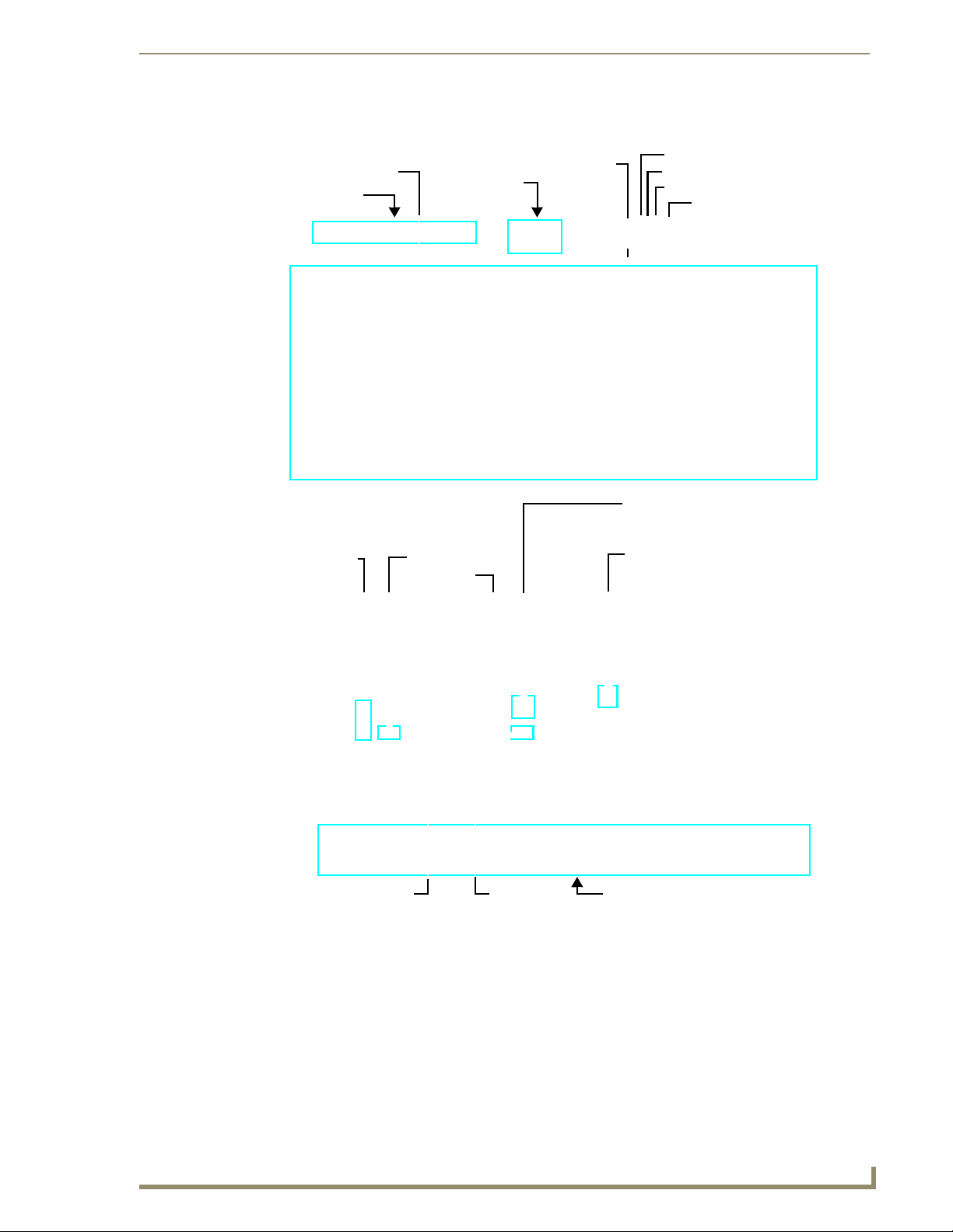
Networking Specifications for MAX Servers
It is required that the control segment of the network (using the ETHERNET CONTROL
connector) is kept separated from the (switched) content delivery segment (using the A/V OUT
connector), as indicated in FIG. 10.
FIG. 10 Network Segment Layout
MAX Servers: HT Home Theater and MMS Multimedia Servers
19
Page 26

MAX Servers - Setup and Configuration
Online Database
MAX systems (firmware version 4.34 or higher) rely on an online media database for disc recognition.
The online database provides all media information (such as disc title, track/chapter information, artist
information, etc.). In order to identify discs (CDs and/or DVDs) as they are added to the MAX Server,
the MAX Server must have permanent access to the internet.
Previous versions of the MAX Servers utilize a database that resides on the server,
and therefore do not require a permanent connection to the internet. The shift from an
onboard media information database (updated periodically) to a dynamic online
database will provide more accurate and consistent results when identifying new
media as they are added to the MAX Server.
Without access to the internet, all media information must be entered manually.
Mandatory 24-Hour Initialization Period (HT Servers only)
IMPORTANT! MAX-HT Servers require a 24-hour initialization period (to charge and initialize the
RAID batteries). This simply entails powering up the server and letting it charge and initiate for 24 hours
before use.
Failure to allow this initialization to complete may cause performance problems during media playback.
If Power Is Removed From the HT Server
If for reason power is removed from the HT Server for any length of time more than one hour, the RAID
batteries will begin to discharge. Partially discharged batteries may cause performance problems during
media playback.
In the event that the HT Server has sat without power for more than an hour, you should allow the server
to charge for up to 18 hours to ensure that the batteries are fully charged, before use.
For best results, always use a UPS with MAX Servers and avoid removing all power
from the unit.
Step 1: Connect a Mouse, Keyboard and VGA Monitor
PS/2 Keyboard port
PS/2 Mouse port
Note: minor layout variations exist between the MMS and HT servers for example, there is no parallel printer port on the HTs, and the USB 1
port is located outside of this panel.
FIG. 11 MAX Servers - rear panel connectors
VGA Out
20
MAX Servers: HT Home Theater and MMS Multimedia Servers
Page 27

MAX Servers - Setup and Configuration
Static electricity can damage electronic circuitry. Before touching the MAX server,
discharge any accumulated static electricity from your body by touching a grounded
metal object.
Connect a PS/2 mouse and keyboard, and a VGA monitor directly to the MAX server to access the onboard interface, called the MAX Admin Menu (FIG. 12). You’ll use the options in the Admin Menu to
configure communication settings and add/remove MAX-AVP Audio/Video Players as well as MAXAVM and MAX-AOM modules.
Alternatively, you can access the MAX Admin Menu via Telnet, using the Server
Configuration feature in the WInMAX software. This requires that the MAX server is
configured with an IP address and Subnet Mask settings which are appropriate for
your network configuration. Refer to “Step 6: Install and Configure WinMAX Software”
for details.
Step 2: Connect the Power Cable(s) and Apply Power
Consider using a UPS with the MAX server, modules and ethernet switch (if
applicable).
MMS-01S, -02S, -02SB and MAX-HT Servers:
Connect the power supply, using the supplied power cord.
1.
2. Flip the Master Power Supply switch to On.
3. Push the Power On/Off pushbutton to apply power.
4. Allow up to one minute for the server to boot-up.
MMS-04S and -12S Servers:
Connect both of the power supplies, using the supplied power cords.
1.
2. Push the Power On/Off pushbutton to apply power.
3. Allow up to one minute for the server to boot-up.
MMS-900 Servers:
Connect all of the (4) power supplies, using the supplied power cables.
1.
2. Turn on the Power switch (on the front panel) to apply power.
3. Allow up to one minute for the server to boot-up.
MAX-HT Servers:
1.
Connect the power supply, using the supplied power cord.
2. Flip the Master Power Supply switch to On.
3. Push the Power On/Off pushbutton to apply power.
4. Allow up to one minute for the server to boot-up.
MAX Servers: HT Home Theater and MMS Multimedia Servers
21
Page 28

MAX Servers - Setup and Configuration
Step 3: Access the MAX Admin Menu
Once the boot-up process is complete, the MAX Admin Menu (FIG. 12) is displayed:
FIG. 12 MAX Admin Menu
The MAX Admin Menu allows access to various administrative functions for the MAX server.
Working With the MAX Admin Menu
Use the arrow keys on the keyboard to highlight the desired option, and press Enter to make a
selection. Do not use the arrow keys on your keyboard’s numeric keypad.
Beyond this menu, press the TAB button to navigate through the elements on the pages until
an asterisk appears next to the desired selection.
Press the spacebar to make a selection (press again to de-select).
For detailed descriptions of all options in the MAX Admin Menu, refer to the MAX
Admin Menu section on page 27.
Step 4: Add MAX-AVPs and AVM/AOM Modules to the HT Server
Before you can use MAX-AVP Audio-Video Players MAX-AVM or MAX-AOM modules, they must
each first be added to the server, via the Output Module Setup options in the MAX Admin Menu. You
should add the modules/players to the server before making any physical connections.
Adding MAX-AVP Players and/or MAX-AVM Modules
Complete these steps for each MAX-AVM Audio-Video module and/or MAX-AVP Audio-Video Player
that you want to add to the MAX-HT:
22
HT Servers treat MAX-AVPs exactly the same as MAX-AVMs, and the process of
adding them is identical.
1. In the MAX Admin Menu, select: Output Module Setup > Add Output Module > AVM.
2. In the Enter Output Number field, specify the output on the server that you want to assign to this
AVP or AVM (range = 1 - 33). Each AVP/AVM requires one output. Select OK to proceed.
MAX Servers: HT Home Theater and MMS Multimedia Servers
Page 29

MAX Servers - Setup and Configuration
Note: The server will not allow you to assign a module to an output/zone that is already in use.
Select Output Module Setup > View to review the current
output/zone assignments.
3.
In the Enter Serial Number field, enter the Setup Serial (Key) Number. This number is printed on a
decal located on the bottom of each AVM/AVP enclosure. The system will notify you that the AVP
(or AVM) has been added to the system.
MAX-AVMs use a Setup “Serial” Number; MAX-AVPs use a Setup “Key” Number.
4. Select OK to return to the Output Module Setup menu, select OK again to return to the main menu.
5. Select Restart MAX daemon.
Adding MAX-AOM Audio-Only Modules
Complete these steps for each MAX-AOM module that you want to add to the HT:
1. In the MAX Admin Menu, select Output Module Setup > Add Output Module > AOM.
2. In the Enter Output Number field, specify the first of up to 4 outputs on the server that you want to
assign to this AOM (range = 1 - 33).
Each AOM requires up to 4 server outputs to accommodate the 4 audio output/zones provided
by each AOM. Since the MAX-HT12 supports two AOMs (one on each USB port), you can
assign up to 8 server outputs. Select OK.
3.
In the Enter USB Port Number field, enter the number of the USB port (1 or 2) on the server that this
MAX-AOM will be physically connected to. Select OK.
4. In the Enter AOM Output Number field, specify which audio output/zone on the MAX-AOM (1-4)
you are adding to the specified server output. Select OK.
5. A message is displayed to notify you that the AOM module has been added to the system. Select
OK to return to the Output Module Setup menu.
Repeat these steps to assign each of the AOM’s four audio output/zones to a USB port and
Output number on the server.
Notes:
Always assign 4 consecutive server outputs to each MAX-AOM, even if you don’t plan to use
all of the AOM’s outputs right away.
Assign the 4 server outputs (per AOM) starting either with output #1 (if there are no AVPs/
AVMs on this server), or immediately after the last output assigned to an AVP or AVM.
To avoid potential confusion later, do not mix AOM outputs and AVP/AVM outputs on the
server.
6. Select Restart MAX daemon.
Additional Information on USB Ports: MMS-01S, -02S and 02SB Servers
The 2 built-in audio outputs on the MMS-01S, -02S and -02SB servers utilize the internal USB 1 port on
the server. To add an external AOM module to the MMS-01S server, it is important to understand that:
The two built-in audio outputs occupy audio outputs 1 and 2 on USB 1, leaving outputs 3 and
4 on USB port 1 open.
The USB port on the rear panel of the server which is used to connect an additional external
MAX-AOM module is USB 2.
If you connect an external AOM module to USB 2, the four audio outputs on that AOM will
use ports 3 and 4 on USB 1 (the ports that are unused by the two built-in audio outputs), as
well as ports 1 and 2 on USB 2 (as indicated in the table below):
MAX Servers: HT Home Theater and MMS Multimedia Servers
23
Page 30

MAX Servers - Setup and Configuration
MMS Output/Zone (1-33) USB Port Connection (1 or 2) Audio Output (1-4)
1 1 1‘
2 1 2
3 1 3
4 1 4
5 2 1
6 2 2
7...(to 33) AVM 3...
Additional Information on USB Ports: MMS-04S, -12S, -900 and MAX-HT Servers
If you are using both USB connectors on the MAX server, be sure to note which audio zones are
associated with the AOM connected to each USB port:
The USB 1 port is for audio zones 1 through 4.
The USB 2 port is for audio zones 5 through 8.
In this scenario, if the AOM connected to USB port 1 on the server (providing AOM outputs 1-4) is
unplugged or experiences any other failure, then USB port 2 takes over and behaves like port 1.
As a result, the AOM connected to USB port 2 will switch from providing AOM zones 5-8 to providing
audio zones 1-4, the next time the server is rebooted.
Step 5: Connect the Modules To the MAX Server
Once the AVP players and AVM/AOM modules have been added to the server via the MAX Admin
Menu, you can physically connect them to the server:
Connecting MAX-AVPs and/or MAX-AVMs
Multiple AVMs/AVPs require a GB Ethernet switch (not included).
Connect the audio outputs, using either one of two options:
1.
a. Use a mini-stereo to RCA adapter for analog audio output
b. Use a coaxial cable for digital audio output
2. Use a S-Video cable to connect the video output on the AVM or AVP to a display device (MAX-
AVMs also support VGA connections).
3. Use ethernet cables to connect the ethernet port on the AVM or AVP to a GB ethernet switch (not
included), and the GB ethernet switch to the A/V OUT connector on the server.
4. Connect the included power supply.
5. Push the power button on the front panel of the AVM, and allow up to one minute for the module to
boot up. On the AVPs, the power switch is on the rear panel.
Power up the MAX-HT before applying power to the AVP(s) and/or AVM(s).
24
MAX Servers: HT Home Theater and MMS Multimedia Servers
Page 31

MAX Servers - Setup and Configuration
Connecting MAX-AOM Modules
Do not use a USB hub with MAX-HT servers or AOM modules.
Connect the MAX-AOM(s) to an audio system (amplifier, switcher, etc.), using one of two options:
1.
a. Use RCA cables for analog stereo output (L and R)
b. Use a coaxial cable for digital audio output (D)
2. Connect the included power supply to apply power to the AOM.
3. Use the supplied USB cable to connect the AOM module to a USB port on the server.
When connecting USB cables to the HT server, always plug into the USB 1 port
first. The USB 1 port is located on the right side of the rear panel (see FIG. 3).
Power up the AOM(s) before connecting them to the server.
Step 6: Install and Configure WinMAX Software
Once the MAX-AVP and AVM/AOM modules have been added and connected to the MAX server, you
can use the WinMAX software application to initiate and control playback of movies or music.
If it is not already installed, load the WinMAX application on your PC. WinMAX can be downloaded
from www.amx.com as a self-extracting executable.
If you intend to connect to the MAX via a LAN connection, verify that the PC is communicating
properly with the network, and that the MAX server is powered and booted up.
For WinMAX to be viewed properly, set your PCs resolution to 1024 x 768.
1. Use an ethernet cable to connect the ETHERNET CONTROL port on the MAX server to the LAN
that the PC running WinMAX is on.
2. Launch the WinMAX software on your PC and open the System Information tab, where you can
specify the network address of the MAX server.
3. Change the Server’s IP Address or URL field to match that of the MAX server you are connecting
to. Click on the disk icon next to the text-entry field to save this configuration.
If you are connecting to the MAX server via a direct connection with a PC (using a crossover
ethernet cable), be sure that the IP Address of the Network card in your PC is in the same range
as the server, but not the same as the server. For example a network card setting of
192.168.1.31 will work with an IP address of 192.168.1.30.
4.
The blank fields should fill in momentarily, indicating that the MAX has been recognized.
If You Don’t Connect
Check ethernet cables and verify that all connections are intact.
If you are connecting to the server via a PC network, be sure that the IP address and Subnet
Mask settings are appropriate for your network configuration. Consult your network
administrator for help with this.
MAX Servers: HT Home Theater and MMS Multimedia Servers
25
Page 32

MAX Servers - Setup and Configuration
You can also use WinMAX to establish a Telnet connection with the MAX to access the MAX Admin
Menu: in the WinMAX System Information tab, click on Server Configuration. You will be prompted for
a User Name and Password. These are case sensitive, and by default:
User Name = root
Password = mozart
If you have connected directly to the MAX (as described in Step 1), you will not be
prompted for a User Name or Password.
Loading Media Content on the MAX Server
There are two ways to load media content (DVDs and CDs) onto MAX Servers:
Use the WinMAX software application to add/remove content on the MAX server. Refer to
the WinMAX Instruction Manual for details.
Use the MDL200 MultiDisc Loader System to bulk-load up to 200 discs at a time to the MAX
server. Refer to the MDL200 MultiDisc Loader System Instruction Manual for details.
MAX systems (firmware version x.xx or higher) rely on an online media database for
disc recognition. In order to identify discs (CDs and/or DVDs) as they are added to
the MAX Server, the MAX Server must have permanent access to the internet. See
the Online Database section on page 20.
Without access to the internet, all media information must be entered manually.
DVD and CD Playback
Once you have established communication with the MAX server via WinMAX, you can use WinMAX
to initiate and control playback of movies or music.
Playing a DVD
In WinMAX, open the Movies tab. Then, select a DVD title (MAX servers ship with one DVD loaded
and ready for playback), and click the Play button.
Playing a CD
Open the Music tab. Then, select a CD title (MAX servers ship with one CD loaded and ready for
playback), and click the Play button.
Periodic Updates
The MAX server can receive periodic updates for its system software and internal information database.
In order to receive updates, the PC running WinMAX and the server must be on the same network, and
the server must be able to access the internet.
Use the options on the IP settings page of the MAX Admin Menu to configure the IP settings of the
server for compatibility with your network. Refer to the IP Settings section on page 30 for details.
Shutting Down the MAX Server
The correct way to shut down the MAX server is via the Shutdown command in the MAX Admin Menu.
This allows the operating system to shut down cleanly and completely before power is removed from the
system.
Always shut down the server this way to avoid the reinitialization process that results from an improper
shut down. The reinitialization process can be time-consuming, and cannot be cancelled.
Refer to the Shutdown section on page 44 for details.
26
MAX Servers: HT Home Theater and MMS Multimedia Servers
Page 33

MAX Admin Menu
Overview
MAX servers utilize a built-in interface called the MAX Admin Menu that allows access to various
administrative functions for the MAX server. To access the MAX Admin Menu, you must establish a
telnet session with the server.
There are two ways to access the MAX Admin Menu - either via the Server Configuration option in
WinMAX, or by connecting directly to the MAX server.
If you use the Server Configuration option in WinMAX, you will be prompted for a User
Name and Pa ssw ord . These are case sensitive, and by default:
User Name = root
Password = mozart
If you have connected directly to the MAX server, you will not be prompted for a User Name
or Password.
Accessing the Admin Menu via WinMAX
If there is already a PC running the WinMAX software application connected to the same LAN as the
MAX server, you can use WinMAX to establish a telnet connection to the server and access the MAX
Admin Menu (FIG. 13):
MAX Admin Menu
WinMAX - System Information tab
MAX Server Configuration
(telnet) window with
MAX Admin Menu
FIG. 13 Accessing the MAX Admin Menu via WinMAX
1. Launch WinMAX and open the System Information tab.
2. Verify that a connection exists with the target MAX server.
MAX Servers: HT Home Theater and MMS Multimedia Servers
27
Page 34

MAX Admin Menu
3. Click the Server Configuration button to open the MAX Server Configuration window and
establish a telnet session with the server.
4. You will be prompted to enter a login ID and (Master) password. Once these have been entered
correctly, the MAX Admin Menu is displayed in this window.
Accessing the Admin Menu via Direct Connection to the MAX Server
Alternatively, you can connect a mouse, keyboard and VGA monitor directly to the MAX server, via the
connectors on the rear panel (FIG. 14).
PS/2 Keyboard port
PS/2 Mouse port
Note: minor layout variations exist between the MMS and HT servers for example, there is no parallel printer port on the HTs, and the USB 1
port is located outside of this panel.
FIG. 14 MAX Servers - rear panel connectors
VGA Out
Static electricity can damage electronic circuitry. Before touching the MMS, discharge
any accumulated static electricity from your body by touching a grounded metal
object.
When the server is powered up, you will be prompted to enter a login ID and (Master) password. Once
these have been entered correctly, the MAX Admin Menu is displayed.
MAX Admin Menu Options - Overview
The options in the MAX Admin Menu include:
• System Information: Displays system hardware and status information (read-only).
• IP Settings: These options allow you to view and configure the IP settings of the
server for compatibility with your network.
• Output Module Setup: This set of options allows you to add, view and delete external output
modules (MAX-AVM audio-video modules and/or MAX-AOM audioonly modules), as well as MAX-AVP Audio-Video Players.
• RAID 5 Status: Displays status information for the servers RAID 5 array, including indi-
• RAID 5 CLI: The options on this page are only for use by AMX Technical Support.
• Add RAID Disks: The options on this page allow you to migrate unassigned ports to a
• Log Management: The options on this page allow you to view and delete log files, and
• Date, Time Locale: This set of options allows you to specify/adjust the system’s date, time
• Shell: This option opens an MS-DOS window for sending specific commands
• Modify max.ini The options on this page are only for use by AMX Technical Support.
vidual status for each of the disc drives (read-only).
controller unit.
control the logging level for the server.
and location settings.
directly to the server.
28
MAX Servers: HT Home Theater and MMS Multimedia Servers
Page 35

MAX Admin Menu
• Authenticate HDD: The options on this page allow you to add, remove and view hard disc
• Parental Control: This page allows you to enable parental control functionality.
• Online Tech Support: This option allows you to establish a connection between the MAX
• Disconnect Support: Terminates the connection between the MAX server and AMX Techni-
• Cover Art: This option retrieves updated cover art for discs in the MAX server’s
• Change Region: The options on this page allow you to change the region code setting
• Update Firmware: The options on this page allow you to schedule when the server should
• Restart MAX Daemon: This option restarts the MAX daemon. Restart the daemon to activate
• Shutdown: This set of options allows you to either Reboot or Shutdown the MAX
• Exit: Exits the MAX Admin Menu and terminates the Telnet session.
System Information
drives (HDDs) in the MAX server.
server and AMX Technical Support, for remote troubleshooting and
support operations.
cal Support.
media library.
for the MAX Server’s DVD-ROM.
automatically check for firmware updates (day of week and time), and
to manually update the system immediately (if updated firmware is
detected).
any configuration changes made via the options in the MAX Admin
menu.
server.
FIG. 15
MAX Admin Menu - System Information
The System Information page displays the following system hardware and status information (readonly):
• MAX Model: The model number of the MAX server.
• S/R Number: The 9-digit serial number of this MAX server.
• Firmware Ver.: The version of the firmware currently loaded in the MAX server.
• Date: Today’s date (MM/DD/YY).
MAX Servers: HT Home Theater and MMS Multimedia Servers
29
Page 36

MAX Admin Menu
• Time: Current time (HH:MM:SS)
• Time Zone: Local time zone.
• Total Storage: Total amount of disc space available for content storage on this server.
• Space Used: Total amount of disc space currently being used.
• Available: Amount of disc space currently available for storage.
• No. of CD’s: The number of audio CDs currently loaded in the server’s library.
• No. of DVD’s: The number of DVDs currently loaded in the server’s library.
• RAID Status: The current status of the server’s RAID array.
• Synch Status: The current synch status of the server’s RAID array.
• Media DB: The version and date of the Media Database.
Click OK to return to the MAX Admin Menu.
IP Settings
30
FIG. 16
MAX Admin Menu - IP Settings
These options allow you to view and configure the IP settings of the server for compatibility with your
network.
To edit these settings, press Yes to proceed to the next screen, and press Ye s again to access the
Configure TCP/IP screen (FIG. 17).
To use dynamic IP configuration (BOOTTP/DHCP), press the tab button to navigate through
the elements on the page until an asterisk appears next to Use dynamic IP configuration
(BOOTP/DHCP), and press the spacebar to select this option. Note that once this option is
selected, the other fields on this page are disabled. Press the space bar again to de-select this
option.
If this option is not selected, then you can use the remaining fields in this screen to
manually specify an IP address, NetMask, Default Gateway (IP) and Primary
nameserver for the MAX server.
Press OK to save your changes.
MAX Servers: HT Home Theater and MMS Multimedia Servers
Page 37

MAX Admin Menu
FIG. 17 MAX Admin Menu - Configure TCP/IP
Preparing the MAX Server for Receiving Periodic Updates
The IP Settings (Gateway and Primary DNS) in the WinMAX Server Configuration screen must be set
correctly. To prepare your server for automatic updates:
1. Connect your PC to the Internet and open the WinMAX software.
2. Go to an MS-DOS Command Prompt on your PC and type ipconfig /all then press Enter. Note the
Default Gateway and first DNS Server settings.
3. In the System Information tab, click the Server Configuration button to access the Server
Configuration dialog.
4. Copy the Default Gateway and first DNS Server settings (from step 2) into the Gateway and
Primary DNS fields in the IP Settings section of the Server Configuration dialog.
5. Press Save Configuration. The server is now ready for auto-updates.
Output Module Setup
FIG. 18 MAX Admin Menu - Output Module Setup
This set of options allows you to add, view and delete external output modules (MAX-AVM audio-video
modules and/or MAX-AOM audio-only modules), as well as MAX-AVP Audio-Video Players.
MAX Servers: HT Home Theater and MMS Multimedia Servers
31
Page 38

MAX Admin Menu
MAX-HT Home Theater Servers treat MAX-AVP Audio-Video Players exactly the
same as MAX-AVP modules, and the process of adding AVPs is the same as that for
AVPs.
MAX-AVPs are supported by HT servers only - they are not supported by MMS
servers.
Adding New Modules to the System
1.
Select Add, then select the type of module (MAX-AOM or MAX-AV M) you are adding (FIG. 19).
FIG. 19 Add Output Module
If you are adding a MAX-AVP (MAX-HT04 and HT12 Home Theater Servers only),
select AVM from the Add Output Module menu.
2. Click OK to proceed. Next you must enter an Output Number for the new module (FIG. 20).
FIG. 20 Add Output Module (
If you are adding a MAX-AOM (audio-only module) then the valid range depends on the type
AOM
and
AVM
)
of server you are using:
MMS-01S, -02S and -02SB servers only support one AOM module, so the output
should always be set to 1.
MMS-04S, -12S and -900 servers support up to two AOM modules, so the output
can be either 1 or 2. If you are only using one AOM with these servers, the output
should be set to 1.
MAX-HT04 and -HT12 Home Theater servers support up to two AOM modules, so
the output can be either 1 or 2. If you are only using one AOM with these servers, the
output should be set to 1.
If you are adding a MAX-AVM audio-video module, the range is 1-25 (all MAX servers
support up to 25 AVMs).
If you are adding a MAX-AVP Audio-Video Player (HT04/HT12 Servers only), the range is
1-25 (MAX-HT04 and MAX-HT12 servers support up to a total of 25 AVMs and/or AVPs).
Click OK to save your changes.
32
MAX Servers: HT Home Theater and MMS Multimedia Servers
Page 39

MAX Admin Menu
Viewing all Modules in the System
Select View in the Output Module Setup page (FIG. 18) to open a read-only list of all modules currently
detected by the server to be installed in the system (FIG. 21).
FIG. 21 Installed Output Modules
Removing Modules From the System
Select Remove in the Output Module Setup page (FIG. 18) to open a list of all modules currently
installed in the system.
To remove one or modules from the system. select each module that you want to remove and press
Delete (FIG. 22).
FIG. 22 Deleting the selected Output Module(s)
RAID 5 Status
This page displays (read-only) status information for the servers RAID 5 array, including individual
status for each of the disc drives (FIG. 23). Press OK to return to the MAX Admin Menu.
MAX Servers: HT Home Theater and MMS Multimedia Servers
33
Page 40

MAX Admin Menu
FIG. 23 MAX Admin Menu - RAID 5 Status
RAID 5 CLI
This set of options rebuilds the server’s RAID array. This option is only for use by AMX Technical
Support.
If the RAID array is rebuilt, all content on the server will be lost and the unit be
rendered inoperable.
34
MAX Servers: HT Home Theater and MMS Multimedia Servers
Page 41

Log Management
MAX Admin Menu
FIG. 24 MAX Admin Menu - Log Management
MAX Servers have the ability to log various internal activities, primarily for troubleshooting purposes.
The options on this page allow you to view and delete log files, and control the logging level for the
server.
Specifying Logging Levels
Select Log Toggles in the Log Management menu to access the Select Log Options menu (FIG. 25),
where you can select which events to include in the logs (RS232, ADA, TCP/IP, and DEBUG).
FIG. 25 Select Log Options
By default, all of the log options are selected for inclusion. Use the spacebar to select/deselect these
options as desired.
Viewing Log Files
To view the log(s) specified in the Select Log Options page, select Current Log from the Log
Management menu. An example log file is shown in FIG. 26.
MAX Servers: HT Home Theater and MMS Multimedia Servers
35
Page 42

MAX Admin Menu
FIG. 26 Example of a log display
Deleting Log Files
Select Delete Log Files from the Log Management menu. The system will prompt you to verify this
action before the files are erased.
Date, Time Locale
This set of options allows you to specify/adjust the system’s date, time and location settings (FIG. 27).
36
FIG. 27 MAX Admin Menu - Date, Time Locale
MAX Servers: HT Home Theater and MMS Multimedia Servers
Page 43

MAX Admin Menu
Setting System Date and Time
When you select Date, Time, Locale from the MAX Admin Menu, a wizard is invoked which steps you
through the process of setting the date and time for the system:
1. The first screen to appear is the Configure Timezones screen (FIG. 28).
FIG. 28 Date, Time, Locale - Configure Timezones
2. Select wether to set the hardware clock to GMT (Greenwich Mean Time). Use the tab key to
navigate through the elements on the page, and use the spacebar to select or de-select this option.
3. Scroll through the list to highlight the correct time zone for the server. Use the spacebar to make
your selection.
4. Click OK to proceed to the Set New Date screen (FIG. 29). Use this screen to set the current Month,
Year and Day for the server. To adjust these values, you must first move the highlighted cursor into
the area that you want to adjust. Then, use the up and down arrow keys to adjust the selected
element.
FIG. 29 Date, Time, Locale - Set New Date
To change the month, move the highlighted cursor to the Month window and use the up/down
arrow keys to scroll forward or backward through the months. Press the spacebar to select the
correct month.
To change the year, move the highlighted cursor to the Year window and use the up/down
arrow keys to scroll forward or backward through the years. Press the spacebar to select the
correct year.
To change the date, move the highlighted cursor to the Date window and use the arrow keys to
navigate to the correct date. Press the spacebar to select the correct date.
MAX Servers: HT Home Theater and MMS Multimedia Servers
37
Page 44

MAX Admin Menu
5. Click OK to proceed to the Set New Time screen (FIG. 30), where you can set the system time (in
HH:MM:SS format). To adjust the time settings, move the highlighted cursor to the time field that
you want to adjust and use the up and down arrow keys to adjust the value up or down.
FIG. 30 Date, Time, Locale - Set New Time
6. Click OK to proceed to the final screen which displays the new Date and Time settings (FIG. 31).
Click OK to save your changes and return to the MAX Admin Menu.
FIG. 31 Date, Time, Locale - New Date and Time settings
Shell
This option opens an MS-DOS window for sending specific commands directly to the server.
Modify max.ini
38
FIG. 32 MAX Admin Menu - Modify max.ini
These options on this page are only for use by AMX Technical Support.
MAX Servers: HT Home Theater and MMS Multimedia Servers
Page 45

MAX Admin Menu
Authenticate HDD
The set of options on this page allow you to add, remove and view hard disc drives (HDDs) in the MAX
server (FIG. 33).
FIG. 33 MAX Admin Menu - Authenticate HDD
For detailed instructions on replacing HDDs in MAX Servers, refer to the Replacing
HDDs in MAX Servers section on page 51.
The options in the Authenticate HDD menu include:
Add: Select to authenticate a new HDD, as described in the previous section.
View: Select to view all the serial numbers and keys for HDDs in the system.
Remove: Select to remove a selected HDD from the system. One or more drives can be
removed at a time.
Authenticating a new HDD
Select Authenticate a New HDD from the MAX Admin Menu.
1.
2. Enter the 8-digit serial number of the HDD. (printed on a decal located on the bottom panel of the
HDD).
3. Enter the 16-digit authentication key supplied by AMX for that HDD (printed on a slip of paper
included with the replacement drive).
MAX Servers: HT Home Theater and MMS Multimedia Servers
39
Page 46

MAX Admin Menu
FIG. 34 Admin Menu, Authenticate HDD, and Add HDD dialogs
Viewing All HDDs In the MAX Server
Select View from the Authenticate HDD menu to view all the serial numbers and keys for HDDs in the
system (FIG. 35). Note that this list only indicates HDDs that have been successfully authenticated.
FIG. 35 Authenticate Menu - View HDD
Removing HDDs From the MAX Server
Select Remove from the Authenticate HDD menu to remove a selected HDD from the system. One or
more drives can be removed at a time.
Select the HDD(s) that you want to remove from the system, then select Delete (FIG. 36).
FIG. 36 Authenticate Menu - Select HDD(s) to Remove dialogs
Once the HDD(s) have been removed from the System, they can be physically removed from the server
without damaging the RAID array.
40
MAX Servers: HT Home Theater and MMS Multimedia Servers
Page 47

Parental Control
MAX Admin Menu
FIG. 37 MAX Admin Menu - Parental Control
This page allows you to enable parental control functionality. To enable parental control, enter a new
parental control password and select OK.
Online Tech Support
FIG. 38 MAX Admin Menu - Online Tech Support
This option allows you to establish a connection between the MAX server and AMX Technical Support,
for remote troubleshooting and support operations.
MAX Servers: HT Home Theater and MMS Multimedia Servers
41
Page 48

MAX Admin Menu
Cover Art
This option retrieves updated cover art for discs in the MAX server’s media library.
Change Region
The information in this document concerning region code settings does not apply to
the MMS-12S Server, since the MMS-12S does not feature a DVD-ROM drive.
The region code setting for the MAX Server’s internal DVD-ROM drive must match the region code of
the DVD(s) you are attempting to load.
If a DVD is inserted that has a region code that is different from that of the DVD-ROM in the MAX
Server, you will receive an error message indicating that there is no disc in the drive when you press the
Identify Disc button in the Record tab.
By default, the MAX Server’s DVD-ROM drives are set to read DVDs with Region 1 encoding (for U.S.,
Canada and U.S. Territories). Depending on what region of the world you are installing and operating the
MAX, you may need to change the region code setting in order to read DVDs.
NOTICE: You can change the region code setting on your MAX Server’s DVD-ROM drive up to five
times, and no more. The region code setting is locked down in the DVD-ROM drive the fifth time it is
set, permanently setting to that last region code setting. At that point there is no way to change the
region code setting again. The number of resets still available is indicated at the top of the Change
Region page.
The region code setting for the MAX Server’s DVD-ROM can be changed via the Change Region
option in MAX Admin Menu (accessible via the Server Configuration option in WinMAX):
The number of region
code setting resets
still available is
indicated here
(Max resets = 5).
FIG. 39 MAX Admin Menu - Change Region
In the event that you expect to load large numbers of DVDs with different region codes, you should
group the DVDs together by region to minimize the number of times you’ll have to change the region
42
MAX Servers: HT Home Theater and MMS Multimedia Servers
Page 49

MAX Admin Menu
code setting (keeping in mind that it can only be changed a maximum of five times). Also, insure that the
last region code setting made matches the region in which the MAX will be installed.
Changing The Region Code Setting On Your MAX Server
Insert a DVD with your local region coding in the MAX Server’s DVD-ROM drive.
1.
2. In the System Information tab, click the Server Configuration button to access the Admin Menu.
3. Use the arrow button on your keyboard to scroll down and highlight the Change Region option.
4. Press the Return (Enter) to open the Change Region page.
5. Use the up/down arrow buttons on your keyboard to select the appropriate region code setting for
your region, and press the spacebar to make your selection (indicated by an "X" to the left of the
number).
The number of resets still available is indicated at the top of the Change Region page (FIG. 39).
Update Firmware
FIG. 40 MAX Admin Menu - Update Firmware
This set of options allows you to schedule when the server should automatically check for firmware
updates (day of week and time), and to manually update the system immediately (if updated firmware is
detected).
Scheduling Automatic Firmware Updates
Select Schedule from the Update Firmware page to schedule a day of the week and time to check for
firmware updates.
The first page that is invoked is the Day Of Week page (FIG. 41). Use the spacebar to select the day that
you want the check to be performed. Select OK to save your changes and proceed to the Select Time page
where you will specify a time for the check to be performed.
If an update is detected, the firmware will automatically be downloaded and installed on the MAX
server.
MAX Servers: HT Home Theater and MMS Multimedia Servers
43
Page 50

MAX Admin Menu
FIG. 41 Update Firmware > Schedule > Day of Week and Select Time options
Manually Updating the Firmware
Select Update from the Update Firmware page (FIG. 40) to manually check for firmware updates for the
server. If an update is detected, it is automatically downloaded and installed.
Restart MAX deamon
This option restarts the MAX daemon. Restart the daemon to activate any configuration changes made
via the options in the MAX Admin menu.
Shutdown
FIG. 42 MAX Admin Menu - Shutdown
This set of options allows you to either Reboot or Shutdown the MAX server.
Exit
This option exits the MAX Admin menu.
Exit and Disconnect
This option exits the MAX Admin menu and terminates the connection to AMX Support (established via
the Online Tech Support option).
44
MAX Servers: HT Home Theater and MMS Multimedia Servers
Page 51

DVD Region Code Settings
Overview
All DVD players and most DVD discs are labeled for operation within a specific geographical region in
the world. This is know as a Region Code.
DVD discs are encoded for a specific region, and must match the region code of the physical DVD drive
to be played. Region code recognition only applies to the physical DVD disc and the physical DVDROM drive. For example, the U.S. is in Region 1. This means that all DVD players sold in the U.S. are
made to Region 1 specifications. As a result, Region 1 players can only play Region 1 DVD coded discs.
Regional codes are entirely optional for the maker of a DVD disc. Discs without region locks
will play on any DVD player in any country.
DVD discs may have multi-region codes, such as Region 1,2 and 4 and will play in drives
coded with the corresponding region code. On the back of each DVD package, you will a find
a region number (1 thru 6).
On a MAX system, if a DVD disc is inserted into a DVD-ROM drive that has a region code
different from that of the DVD, you will receive an error message indicating that there is no
disc in the drive when you attempt to identify the disc (via the Identify Disc option in the
WinMAX software application.
DVD Region Code Settings
The information in this section does not apply to the MMS-12S Server, since the
MMS-12S does not feature a DVD-ROM drive.
DVD Regions (1-6)
The following table lists the six international DVD Region Codes used by all DVD-ROMs:
• REGION 1: USA, Canada
• REGION 2: Japan, Europe, South Africa, Middle East, Greenland
• REGION 3: S.Korea, Taiwan, Hong Kong, Parts of South East Asia
• REGION 4: Australia, New Zealand, Latin America (including Mexico)
• REGION 5: Eastern Europe, Russia, India, Africa
• REGION 6: China
2
1
4
2
5
2
5
2
6
3
4
MAX Servers: HT Home Theater and MMS Multimedia Servers
45
Page 52

DVD Region Code Settings
Default Region Code Setting
By default, the MAX Server’s DVD-ROM drives are set to read DVDs with Region 1 encoding (for
U.S., Canada and U.S. Territories). Depending on what region of the world you are installing and
operating the MAX, you may need to change the region code setting in order to read DVDs.
There are three sources used for loading content onto a MAX server:
1. MDL200 with BulkRipper software running on Windows PC.
2. WinMAX running on a Windows PC - load content from local DVD/CD-ROM drive on PC.
3. MAX Server DVD/CD ROM drive - use WinMAX software for accessing the server’s
DVD-ROM drive.
All of the above methods require the use of physical DVD/CD ROM drives that are covered by the DVD
CCA licensing organization. Each DVD-ROM drive adheres to the requirement that the drive must be set
to a region specific code to play authorized DVDs for that region. The requirement allows for the DVDROM region code to be changed a maximum of five (5) times in a drive. The fifth time, the region code
is "locked" permanently in the drive. This procedure is mandated for all DVD-ROM manufactures that
carry the DVD logo and applies to all DVD-ROM drives used throughout the MAX system.
Using Windows, the properties of the physical DVD drives can be accessed and region code
changed as required.
By default, the MAX Server, MDL200 and MAX-AVP DVD-ROM drives are set to read
DVDs with Region 1 encoding (for U.S., Canada and U.S. Territories). Depending on what
region of the world you are installing and operating the server, you will need to change the
region code setting of the DVD-ROM drive in the server, MDL200 and/or PC in order to read
DVDs from other regions.
Changing the Region Code Setting on MAX Servers
MAX-MMS Servers (MMS-01S, -02S, -02SB, -04S and -900), MAX-HT Servers (MAX-HT04 and HT12), and the MDL200 Multi-Disc Loader feature internal DVD-ROM drives. The region code setting
for the internal DVD-ROM must match the region code of the DVD disc(s) you are attempting to load.
If the region code setting on the DVD-ROM does not match that of the DVD disc that is inserted into the
drive, the disc will not be recognized.
The region code setting for the MAX Server’s DVD-ROM can be changed via the Change Region
option in MAX Admin Menu (accessible via the Server Configuration option in WinMAX):
46
MAX Servers: HT Home Theater and MMS Multimedia Servers
Page 53

The number of region code setting resets still available
is indicated here (Max resets = 5).
DVD Region Code Settings
FIG. 43 MAX Admin Menu - Change Region
You can change the region code setting on your MAX Server’s DVD-ROM drive up to
five times, and no more. The region code setting is locked down in the DVD-ROM
drive the fifth time it is set, permanently setting to that last region code setting. At that
point there is no way to change the region code setting again.
The number of resets still available is indicated at the top of the Change Region page (see FIG. 43).
In the event that you expect to load large numbers of DVDs with different region codes, you should
group the DVDs together by region to minimize the number of times you’ll have to change the region
code setting (keeping in mind that it can only be changed a maximum of five times).
Also, insure that the last region code setting made matches the region in which the MAX will be
installed.
Changing the DVD Region Code Setting On MAX Servers
1. Insert a DVD with your local region coding in the MAX Server’s DVD-ROM drive.
2. In the System Information tab, click the Server Configuration button to access the Admin Menu.
3. Use the arrow button on your keyboard to scroll down and highlight the Change Region option.
4. Press the Return (Enter) to open the Change Region page.
5. Use the up/down arrow buttons on your keyboard to select the appropriate region code setting for
your region, and press the spacebar to make your selection (indicated by an "X" to the left of the
number).
The number of resets still available is indicated at the top of the Change Region page (FIG. 43).
Refer to the MAX Admin Menu section on page 27 for information on the other options available in the
Admin Menu.
MAX Servers: HT Home Theater and MMS Multimedia Servers
47
Page 54

DVD Region Code Settings
48
MAX Servers: HT Home Theater and MMS Multimedia Servers
Page 55

MAX Servers DVD Drives - Supported Formats
MAX Servers DVD Drives - Supported Formats
DVD Drives - Compatible Formats
The following tables indicate the compatibility of several common DVD Drives used in MAX Servers,
relative to DVD formats:
DVD Drives - Compatible Formats
Drive Model DVD-ROM DVD-R DVD-RW DVD+R DVD+RW DVD-RAM DVD+R DL DVD±RW
Panasonic CW-8124-B X X X X
Plextor PX-504A X X X X
Plextor PX-708A X X X X
Sony CRX820E
Sony CRX835E
Sony CRX850E X X X X X X
Toshiba SD-R2412 X X X X
Toshiba SD-R2512 X X X X
MAX Servers - DVD Drives Used
The following table indicates the type of DVD Drive used in each model of MAX Server:
MAX Servers - DVD Drives Used
Panasonic Plextor Plextor Sony Sony Sony Toshiba Toshiba
CW-8124B PX-504A PX-708A CRX820E CRX835E CRX850E SD-R2412 SD-R2512
MMS-01S X X
MMS-02S XX
MMS-02SB XX
MMS-04S XX
MMS-12S n/a n/a n/a n/a n/a n/a n/a n/a
MMS-900 X
MMS125 X X
MMS200 X X
MMS300 X X
MMS350 X X
MMS400
MMS900 X X
MMS-HT4 X
MMS-HT12 X
MAX-AVP X
MAX Servers: HT Home Theater and MMS Multimedia Servers
49
Page 56

MAX Servers DVD Drives - Supported Formats
MDL Series - DVD Drives
The following table indicates the compatibilities of the DVD Drives in the MDL Series (Powerfile):
MDL Series (PowerFile) - DVD Drives
C200ROM and C200 • DVD-ROM, DVD-R
R200ROM • DVD-ROM, DVD-R, DVD-RW, DVD+R, DVD+RW, DVD-RAM,DVD+/-RW
R200ROM • Reads all formats listed above
50
MAX Servers: HT Home Theater and MMS Multimedia Servers
Page 57

Replacing HDDs in MAX Servers
Overview
MAX MMS and HT servers support hot-swappable hard disk drives (HDDs), accessible behind the
removable faceplate, on the front panel. Typically a new HDD will be required only if an existing one
has failed.
The MMS-01S, MMS-02S, MMS-04S and MMS-12S servers all utilize 250GB hard drives,
and require the MMS-HDD250G 250GB drive (FG 2178-250) for replacements.
The MMS-900 server utilizes 300GB hard drives, and requires the
MMS-HDD300G 300GB drive (FG 2178-300) for replacements.
MAX-HT servers utilize 400GB hard drives, and require the 400GB drive (FG 2178-400) for
replacements.
Only HDDs provided by AMX can be used as replacements in MMS servers, and in order to replace a
HDD in an MMS server, the drive must be installed and authenticated according to the steps outlined in
this document.
Replacing HDDs in MMS Servers
Replacing HDDs in MAX Servers
There are several operations that are required to successfully replace an HDD in a MMS server, all of
which are described in the following subsections:
1. Identify the drive that needs to be replaced.
2. The physical removal of the damaged HDD, and the subsequent installation of the replacement
HDD.
3. A rebuild of the RAID array on the new HDD (required in order to add it to the server’s RAID
array).
4. Authentication of the new HDD with the MMS server. Note that before the HDD can be
authenticated to the server it must first be added into the array.
The MMS-01S server does not utilize a RAID disk-drive system. In this case there is
no need to rebuild the array (as described below), but the replacement HDD still
needs to be authenticated (see “Step 4: Authenticate the New HDD” below).
Step 1: Identify the Drive That Needs To Be Replaced
To identify the drive that needs to be replaced, you’ll use the server’s built-in Disk Management Utility
tool. This requires that you have a PC connected to the MMS:
If you intend to connect to the MMS via a LAN connection, verify that the PC is
communicating properly with the network.
Use an RJ-45 twisted pair cable to connect the Ethernet port on the MMS to the LAN that your
PC is on.
Once you have established communication between the MMS server and your PC, you’ll use your web
browser to access the server’s Disk Management Utility interface to see which port has failed. You’ll
need this information to identify the physical HDD that needs to be pulled from the unit and replaced:
1. Launch a web browser (i.e. Internet Explorer).
2. Enter the IP address of the target MMS server in the address bar (example:
http://192.168.1.30:1080). You can use the WinMAX program to determine the server’s IP address
(displayed in the System Information tab).
MAX Servers: HT Home Theater and MMS Multimedia Servers
51
Page 58

Replacing HDDs in MAX Servers
Don’t forget to include the port number.
If you are using Mozilla as your browser, you’ll need to override the security that
blocks port 1080. To unblock port 1080, add the following line (located at /usr/lib/
mozilla/defaults/pref/all.js):
pref(“network.security.ports.banned.override”,”1080”)
Press Enter to open the Disk Management Utility - Home Page (FIG. 44).
3.
FIG. 44 Disk Management Utility - Home page
4. Click on the Configure tab at the top of the screen to access the Configure page (FIG. 45) which
lists all drives in each array and their status. If a drive has failed, it will be labeled “Degraded” rather
than “OK”.
52
MAX Servers: HT Home Theater and MMS Multimedia Servers
Page 59

Degraded
Replacing HDDs in MAX Servers
FIG. 45 Disk Management Utility - Configure page
5. Note the Port Number of the Degraded drive, and determine which physical drive needs to be
replaced in the server:
For MMS servers, refer to the charts in FIG. 46 to determine the physical location of the drive
in question:
PORT 0 PORT 1 PORT 2 PORT 3
PORT 2
PORT 1
PORT 0
PORT 0
PORT 1
PORT 2
PORT 3
PORT 5
PORT 4
PORT 3
PORT 6
PORT 7
PORT 8
PORT 9
PORT 8
PORT 7
PORT 6
PORT 12
PORT 13
PORT 14
PORT 15
PORT 11
PORT 10
PORT 9
PORT 18
PORT 19
PORT 20
PORT 21
MMS-04S (front)
MMS-12S (front)
MMS-900 (front)
PORT 4
PORT 5
FIG. 46 Port to HDD correlation - MMS-04S, MMS-12S and MMS-900 servers
MAX Servers: HT Home Theater and MMS Multimedia Servers
PORT 10
PORT 11
PORT 16
PORT 17
PORT 22
PORT 23
53
Page 60

Replacing HDDs in MAX Servers
Also note that the LED on the degraded drive should blink to indicate that it needs to be replaced.
Once you have determined which drive needs to be replaced, you can proceed to physically removing the
bad drive, and installing the replacement drive.
Step 2: Physical Removal and Replacement of the Drives
1
Push tab to the right to unlock the hinged front panel
MMS Servers
hinge
FIG. 47 Removable drive/tray assembly - MMS Servers (front panel)
1.
Remove the faceplate from the front panel of the server.
Flip the hinged front panel out,
and use it as a handle to pull the
2
drive/tray assembly out of its slot.
2. Remove the damaged HDD. Each HDD is mounted in a tray that slides in and out of the server. To
remove the drive/tray assembly (FIG. 47):
a. Push the tab on the front of the drive tray to the right to unlock the hinged front panel. Flip the
hinged panel out and use it as a handle to gently pull the drive/tray assembly out of its slot.
b. Remove the drive from the drive tray. The drive is secured to the tray with four screws on the
bottom panel.
3. Install and secure the replacement drive into the drive tray.
4. Slide the replacement drive/tray assembly fully into the slot, and push the hinged front panel back
into its locked position. The LEDs on the front of the HDD should light to indicate that it has been
connected and is communicating properly.
5. Replace the faceplate on the server.
Step 3: Rebuild the RAID Array
Once the new HDD has been installed, the drive must be added to the server’s RAID array. This entails
rebuilding the RAID array on the new HDD.
To rebuild the RAID array, you must have a PC connected to the MMS server:
If you intend to connect to the MMS via a LAN connection, verify that the PC is
communicating properly with the network.
Use an RJ-45 twisted pair cable to connect the Ethernet port on the MMS to the LAN that your
PC is on.
Once you have established communication between the MMS server and your PC, you’ll use your web
browser to access the server’s Disk Management Utility interface:
1. Launch a web browser.
2. Enter the IP address of the target MMS server in the address bar (example: http://
192.168.1.30:1080). You can use the WinMAX program to determine the server’s IP address
(displayed in the System Information tab). Don’t forget to include the port number.
3. Press Enter to open the Disk Management Utility - Home Page (FIG. 44).
4. Click on the Configure tab at the top of the screen to access the Configure page (FIG. 45) which
lists all drives in each array and their status. If a drive has failed, it will be indicated on this page
(labeled “Degraded” rather than “OK”).
54
MAX Servers: HT Home Theater and MMS Multimedia Servers
Page 61

Replacing HDDs in MAX Servers
5. Check the box next to the failed drive that you are removing, and click the Remove Drive button at
the bottom of the screen.
6. Check the box again and click the Add Drive button at the bottom of the page.
7. Check all boxes next to all the drives (only in the array that contains the replaced HDD).
8. Check the Force Continue On Source Errors checkbox at the bottom of the screen.
9. Click the Rebuild Unit button. Expect a delay of approximately two minutes before the rebuild
process begins.
10. Click on the Home tab at the top of the screen to return to the Home page, where you can monitor
the process of the rebuild.
Once started, the process of rebuilding the array should take approximately 1.5 hours to
complete. Do not interrupt this process.
The message “Rebuild Complete” is displayed next to the drive (on the Home page) when the
process is finished.
At this point you can close the Disk Management Utility, and continue to use the server as
usual. There is no need to reboot the server.
Step 4: Authenticate the New HDD
When an HDD is replaced in a MMS server, it must be authenticated before the system will play media
content. HDDs are authenticated using two criteria, unique to each replacement HDD:
HDD Serial Number: 8-characters, printed on a decal located on the bottom of the drive.
HDD Authentication Key: 16-characters, printed on a piece of paper included with the new
HDD.
Before the HDD can be authenticated to the server it must first be added into the
array.
The HDD authentication process is handled via the built-in user-interface on the MMS server which is
accessible via the telnet window provided in WinMAX.
a) Open a telnet session with the MMS server:
Launch WinMAX, open the System Information tab, and verify that you are communicating with
1.
the intended MMS server by checking the Server IP Address or URL field.
2. Click on the Server Configuration button to open a telnet window.
3. After a brief delay, the Admin Menu is displayed (FIG. 48).
b) Authenticate the new HDD:
Select Authenticate a New HDD from the Admin Menu.
1.
2. Enter the 8-digit serial number of the HDD. (printed on a decal located on the bottom panel of the
HDD).
3. Enter the 16-digit authentication key supplied by AMX for that HDD (printed on a slip of paper
included with the replacement drive).
MAX Servers: HT Home Theater and MMS Multimedia Servers
55
Page 62

Replacing HDDs in MAX Servers
FIG. 48 Admin Menu, Authenticate HDD, and Add HDD dialogs
Replacing HDDs in HT Servers
The AMX line of MAX HT servers support hot-swappable 400GB hard disk drives (HDDs), accessible
behind the faceplate on the front panel (FIG. 49). Typically a new HDD will be required only if an
existing one has failed.
FIG. 49 MAX-HT12 Server (front panel)
Replacement HDDs are available from AMX (FG 2178-400).
Only HDDs provided by AMX can be used as replacements in HT servers, and in
order to replace a HDD in an HT server, the drive must be installed and authenticated
according to the steps outlined in this document.
There are several operations that are required to successfully replace an HDD in an HT server, all of
which are described in this document:
1. The physical removal of the damaged HDD, and the subsequent installation of the replacement
HDD.
2. Authentication of the new HDD with the server.
56
MAX Servers: HT Home Theater and MMS Multimedia Servers
Page 63

Replacing HDDs in MAX Servers
Step 1: Identify the Drive That Needs To Be Replaced
To identify the drive that needs to be replaced, access the MAX Admin Menu, via Telnet:
1. Launch WinMAX, open the System Information tab, and verify that you are communicating with
the intended HT server by checking the Server IP Address or URL field.
2. Click on the Server Configuration button to open a telnet window. After a brief delay, the system
prompts you to log in.
By default, the User Name = ROOT, and the Password = MOZART.
Once you have logged in, the Admin Menu is displayed (FIG. 50).
3.
FIG. 50 Admin Menu
4. Select RAID 5 Status. This option displays a listing of HDDs in the HT server. Look for the drive
that is labeled as “Degraded”.
The drives on HT Servers are physically labeled with numbers on the front panel.
HT04 Servers use drives labeled 1-4, and HT12 Servers use drives 1-12 (see
FIG. 51). However, the drives are listed in the RAID 5 Status window (of the Admin
Menu) starting with zero (0). Therefore, note that drive “0” in the Raid 5 Status
window equates to the drive labeled “1” on the front of the HT server. Remember that
each drive number in the Raid 5 Status list is offset by one relative to the labels on
the front of the HT server.
Step 2: Physical Removal and Replacement of the Drives
There are two pieces of data that you must provide to complete the process of adding the replacement
HDD: The new HDD’s Serial Number, and Key.
The Serial Number is printed on a label placed on the top of the HDD. The Serial Number is
located directly beneath the barcode (“S/N WXXXXXXXXXXX”).
The 16-digit Key is printed on a slip of paper included with the HDD.
Be sure to record the Serial Number before inserting the new drive into the server.
1. Lower the faceplate on the front panel of the server. to access the HDDs (FIG. 47).
2. Remove the damaged HDD. Each HDD is mounted in a tray that slides in and out of the server. To
remove the drive/tray assembly:
a. Pull the latch forward to unlock the drive tray. Flip the hinged panel out and use it as a handle to
gently pull the drive/tray assembly out of its slot.
b. Remove the drive from the drive tray. The drive is secured to the tray with four screws on the
bottom panel.
MAX Servers: HT Home Theater and MMS Multimedia Servers
57
Page 64

Replacing HDDs in MAX Servers
Drive number (silk-screen)
FIG. 51 Removable drive/tray assembly (front panel)
3. Install and secure the replacement drive into the drive tray.
4. Slide the replacement drive/tray assembly fully into the slot, and push the hinged latch back into its
locked position. The LEDs on the front of the HDD should light to indicate that it has been
connected and is communicating properly.
5. Return the faceplate to its locked position.
Step 3: Add the New Drive to the System
When an HDD is replaced in an HT server, it must be added to the system:
1. In the Admin Menu, select Authenticate HDD.
2. Select Add, then select OK to proceed to the Add HDD window.
3. Enter the Serial Number for the new drive.
The Serial Number for each replacement drive is printed on a decal placed on the top panel of
the HDD.
When entering the Serial Number, use the following syntax (no quotes): “WD-
WXXXXXXXXXXX”
4.
Enter the 16-digit Key supplied by AMX for that HDD (printed on a slip of paper included with the
replacement drive).
5. Select Restart MAX Daemon (in the Admin Menu).
6. Note: Restarting the MAX Daemon will disconnect WinMAX from the server.
7. Terminate the Telnet session.
The HT Server will rebuild the new drive and add it to the RAID array. There is no need to reboot the
server; the new drive is ready to use.
Pull the latch forward to unlock the drive tray
1
2
Carefully slide the
drive/tray assembly
out of its slot.
58
MAX Servers: HT Home Theater and MMS Multimedia Servers
Page 65

Replacing HDDs in MAX Servers
MAX Admin Menu
Use the other options in the Authenticate HDD menu (accessible via the Admin Menu on the MMS), to
manage all HDDs in the server, as shown in FIG. 48.
FIG. 52 Authenticate Menu - View HDD and Select HDD(s) to Remove dialogs
The options in the Authenticate HDD menu are described below:
• Add: Select to authenticate a new HDD, as described in the previous section.
• View: Select to view all the serial numbers and keys for HDDs in the system. Note that this list only indicates HDDs that have been successfully authenticated.
• Remove: Select to remove a selected HDD from the system. One or more drives can be removed at a time.
Refer to the MAX Admin Menu section on page 27 for more information.
MAX Servers: HT Home Theater and MMS Multimedia Servers
59
Page 66

Replacing HDDs in MAX Servers
60
MAX Servers: HT Home Theater and MMS Multimedia Servers
Page 67

Rack Mounting MAX Servers
CAUTION: Safety Instructions
Use the following safety guidelines to help ensure your own personal safety and to help protect your
system and working environment from potential damage.
Installing systems in a rack without the front and side stabilizers installed could cause
the rack to tip over, potentially resulting in bodily injury under certain circumstances.
Therefore, always install the stabilizers before installing components in the rack.
After installing system/components in a rack, never pull more than one component
out of the rack on its slide assemblies at one time. The weight of more than one
extended component could cause the rack to tip over and may result in serious injury.
Do not move racks by yourself. Due to the height and weight of the rack, a minimum
of two people should accomplish this task.
Before working on the rack, make sure that the stabilizers are secured to the rack, extended to
the floor, and that the full weight of the rack rests on the floor. Install front and side stabilizers
on a single rack or front stabilizers for joined multiple racks before working on the rack.
Always load the rack from the bottom up, and load the heaviest item in the rack first.
Mounting of the equipment in a rack should be such that a hazardous condition is not achieved
due to uneven loading of the rack.
Make sure that the rack is level and stable before extending a component from the rack.
Use caution when pressing the component rail release latches and sliding a component into or
out of a rack; the slide rails can pinch your fingers.
After a component is inserted into the rack, carefully extend the rail into a locking position,
and then slide the component into the rack.
Do not overload the AC supply branch circuit that provides power to the rack. The total rack
load should not exceed 80 percent of the branch circuit rating.
Consideration should be given to the connection of the equipment to the supply circuit and the
effect that overloading of circuits could have on overcurrent protection and supply wiring.
Appropriate consideration of equipment nameplate ratings should be used when addressing
this concern.
Reliable earthing of rack-mounted equipment should be maintained. Particular attention
should be given to supply connections other than direct connections to the branch (e.g. use of
power strips).
The socket outlet shall be installed near the equipment and shall be easily accessible.
Ensure that proper airflow is provided to components in the rack. If installed in a closed or
multi-unit rack assembly, the operating ambient of the rack may be greater than room
temperature. Therefore, consideration should be given to the overall temperature of the rack.
Do not step on or stand on any component when servicing other components in a rack.
Rack Mounting MAX Servers
MAX Servers: HT Home Theater and MMS Multimedia Servers
61
Page 68

Rack Mounting MAX Servers
3
4
4
Rack Mounting MMS-01S/02S/02SB/04S/12S Servers
MMS-01S, -02S, -02SB, -04S and -12S servers come with a Rack-Mounting Kit, which includes the
hardware required to mount the servers in a standard 19-inch (48-cm) rack.
MMS-900 Servers use a more heavy-duty version of the installation kit to
accommodate their size and weight. The Rack-Mounting Kit that comes with the
MMS-900 comes with its own installation instructions.
Each Rack Rail Installation Kit supports one server, and the parts included in the rack rail hardware kit
include:
Two Outer Slide Rails
Two Inner Server Rails
Two Long Extension Brackets
Two Short Extension Brackets
Four 3-hole Locking Plates (with large holes)
Four 3-hole Locking Plates (with small holes)
Variety of screws (20 large, 20 small/long and 20 small/short)
Locking Tab Hole
Outer Slide Rail (2)
Inner Server Rail (2)
Extension Bracket (2 Short)
Extension Bracket (2 Long)
-hole locking plates:
- Large holes
- Small holes
FIG. 53 Included Rack-Mounting Kit Parts
Locking Release Tab
Screws:
• 20 - Large
• 20 - Small/Long
• 12 - Small/Short
You may not need all the parts included in the rack rail hardware kit for every
installation. You may have some parts left over.
The basic steps for installing the MMS server into a rack are:
1. Prepare the Slide Rail Assemblies: The Inner and Outer Rails must be separated before they can be
attached to the MMS and the rack.
2. Attach the Inner Server Rails to the MMS Server.
3. Attach the Extension Brackets to the Outer Slide Rails.
4. Install the Outer Slide Rails in the server.
5. Slide the server (with Inner Server Rails attached) into the Outer Slide Rails in the rack.
Each step is described in more detail in the following subsections.
62
MAX Servers: HT Home Theater and MMS Multimedia Servers
Page 69

Rack Mounting MAX Servers
Step 1: Prepare the Slide Rail Assemblies
The two Outer Slide Rails, and two Inner Server Rails come assembled in the rack rail hardware kit. You
must separate these pieces before beginning. The Inner Server Rails will be attached to the MMS
chassis.
To detach the server rails from the slide rail assemblies:
1. Place the two slide rail assemblies on a flat surface.
2. Extend the Inner Server Rail from the slide rail assembly until the Inner Server Rail release latch
clicks and locks.
3. Holding down the latch on the back side of the Inner Server Rail, slip the server rail out of the inner
slide.
4. Repeat Steps 2 and 3 for the second slide rail assembly.
Set the Inner Server Rails aside. You will attach them to the MMS chassis (as described in the next
section).
Step 2: Attach the Inner Server Rails to the MMS chassis
The inner slide rails attach to the MMS server chassis, with the locking Release Tab facing out from the
server, as indicated in FIG. 54.
Slide the notched end of the rail under the tab in the front of the server and screw into place towards the
rear of the rail using the small/short screws (four per side).
Attach the Inner Server Rails to the MMS chassis (4 small/short screws per side)
Locking Release tab
Slide the end of the Inner Server Rail under the
tab protruding from the side of the MMS server.
FIG. 54 Attaching the Inner Server Rails to the MMS chassis
Step 3: Attach the Extension Brackets to the Outer Rails
The Extension Brackets attach to the outer rails (using the 3-hole locking plates). You will choose either
the Short Extension Brackets, or the Long Extension Brackets, depending on the depth of the rack you
are mounting the MMS into.
1. Attach the Extension Bracket to the Outer Rail using the small/long screws and a 3-hole Locking
Plate, as shown in FIG. 55. Select the type of locking plate (large or small holes) that works best
with the rack you are using.
Depending on the type of rack you are using, you may need to use Extension Brackets on the
front of the server as well.
2.
The feet of the Extension Bracket are placed at the end of the rail. The type of cabinet/rack you are
using will dictate whether the Extension Bracket feet should point in towards the server or out
towards the rack.
3. Repeat the process for the opposite Outer Rail.
MAX Servers: HT Home Theater and MMS Multimedia Servers
63
Page 70

Rack Mounting MAX Servers
Extension Bracket Feet
Outer Rail
front
FIG. 55 Attaching the Extension Bracket to the Outer Rail (using a Locking Plate)
Locking plate
Extension bracket
Step 4: Install the Outer Rail/Extension Racket Assemblies In the Rack
Once both of the Outer Rail/Bracket assembles (from the previous step) are prepared, they can be
installed into the rack cabinet. Follow these steps for both of the Outer Rail/Bracket assemblies:
1. Insert the Outer Rail/Bracket assembly into the rack. Make sure that the Extension Bracket is
situated towards the rear of the rack.
2. Attach the rear end of the Outer Rail/Bracket assembly to the rack with two screws, (securing the
Extension Bracket, Locking Plate and Outer Rail to the rear flange of the rack cabinet).
3. Align the front of the Outer Rail/Bracket assembly to the front flange on the rack, and secure using
two screws.
Step 5: Load the MMS Server Into the Rack
Once the Outer Rail/Bracket assemblies have been installed in the rack cabinet, the MMS server can
slide into the rack, using the Inner Server Rails (already attached to the server chassis):
1. Carefully align the front of the Outer Slide Rails (in the rack) with the Inner Server Rails (on the
MMS server chassis).
2. Slowly slide the MMS server, into the outer slide rails. Keep the MMS parallel to the floor when
sliding the server rails into the slide rails. Tilting the server up or down could result in damage to
the slide rail assembly.
3. Push the locking tabs in to lock into place. The MMS server slides into the rack until the Locking
Release Tabs on the Inner Server Rails engage the Outer Slide Rails.
Be careful when pressing the Inner Server Rail release latches and sliding the server into the
rack. The slide rails could pinch your fingertips.
64
MAX Servers: HT Home Theater and MMS Multimedia Servers
Page 71

Rack Mounting MAX Servers
g
Inner Server Rail
Outer Slide Rail
Extension Bracket
Rack (front)
FIG. 56 Sliding the MMS server chassis into the rack
Rack Mounting HT and MMS-900 Servers
Each MAX-HT server comes with a Rack-Mounting Kit. Each Rack-Mounting Kit supports one server
and includes all hardware required to mount HT servers in a standard 19-inch (48-cm) equipment rack.
The parts included in the Kit include:
2 Slide Rail Assemblies (each consists of a Stationary section, an Intermediate section and a
Chassis section; pre-assembled for shipping)
2 Extension Brackets
2 End Brackets
6 Locking Plates (4-hole) - not required
4 Adapter Bars (9-hole)
10 flat-head screws, 10 round-head screws
Locking Tab Hole
INTERMEDIATE SECTION (2)
STATIONARY SECTION (2)
CHASSIS SECTION (2)
Extension Brackets (2)
Screws: 10 round head, 10 flat head, 10 lockin
FIG. 57 Included Rack Kit Parts
MAX Servers: HT Home Theater and MMS Multimedia Servers
End Brackets (2) Locking Plates (6)
Locking Release Tab
Adapter Bars (4)
nuts
65
Page 72

Rack Mounting MAX Servers
You may not need all the parts included in the kit for every installation.
Before you begin, disassemble the Slide Rail Assemblies: the Stationary, Intermediate and Chassis
sections must be separated before they can be attached to the server and rack.
CAUTION: Safety Instructions
Use the following safety guidelines to help ensure your own personal safety and to help protect your
system and working environment from potential damage.
CAUTION: Installing systems in a rack without the front and side stabilizers installed could cause the
rack to tip over, potentially resulting in bodily injury under certain circumstances. Therefore, always
install the stabilizers before installing components in the rack.
After installing system/components in a rack, never pull more than one component out of the rack on its
slide assemblies at one time. The weight of more than one extended component could cause the rack to
tip over and may result in serious injury.
CAUTION: Do not move racks by yourself. Due to the height and weight of the rack, a minimum of two
people should accomplish this task.
Before working on the rack, make sure that the stabilizers are secured to the rack, extended to
the floor, and that the full weight of the rack rests on the floor. Install front and side stabilizers
on a single rack or front stabilizers for joined multiple racks before working on the rack.
Always load the rack from the bottom up, and load the heaviest item in the rack first.
Make sure that the rack is level and stable before extending a component from the rack.
Use caution when pressing the component rail release latches and sliding a component into or
out of a rack; the slide rails can pinch your fingers.
After a component is inserted into the rack, carefully extend the rail into a locking position,
and then slide the component into the rack.
Do not overload the AC supply branch circuit that provides power to the rack. The total rack
load should not exceed 80 percent of the branch circuit rating.
Ensure that proper airflow is provided to components in the rack.
Do not step on or stand on any component when servicing other components in a rack.
66
Step 1: Install Chassis Sections Onto The Server Chassis
The Chassis Sections mount directly to the server chassis, using the middle row of screws on the server
chassis.
The server has plastic plugs in the holes that you will use to attach the Chassis Sections, to keep the
server chassis sealed in case the server is not rack-mounted.
To see how these parts will mount, visually align the Chassis Sections with the middle row of plugs on
each side of the server, so that the four screw holes on the Chassis Section rail align with the middle row
of plugs on the server.
Make sure to orient the Chassis Sections so that the locking tab button is facing
outwards, and located toward the rear of the server.
1. Remove the four plastic plugs from each side of the MAX server.
2. Install the chassis sections onto the MAX server chassis using 4 flat-head PHILLIPS screws
(included) per side, as shown in FIG. 58.
MAX Servers: HT Home Theater and MMS Multimedia Servers
Page 73

Rack Mounting MAX Servers
(rear)
(front)
HT Server chassis
FIG. 58 Attaching the Chassis Sections to the server chassis
Chassis Sections
The Locking Tab on each Chassis Section should
be oriented towards the rear of the server
Step 2: Slide Intermediate Sections Into the Stationary Sections
1.
Slide the Intermediate Section into the Stationary Section, from the rear end of the Stationary
Section, as shown in FIG. 59.
2. Press the Locking Tab on the Stationary Section to allow the Intermediate Section to slide fully into
place.
Locking tab hole
Breaker tab
(rear)
Breaker Post (on Intermediate Section)
FIG. 59 Sliding the Intermediate Section into the Stationary Section
Stopper
(front)
Locking tab
Stopper (on Stationary Section’s top guide-rail)
3. Slide the Intermediate Section in, to the point that the Breaker tab on the Intermediate Section rests
against the Stopper on the top guide-rail on the Stationary Section, and the locking tab snaps into
place.
MAX Servers: HT Home Theater and MMS Multimedia Servers
67
Page 74

Rack Mounting MAX Servers
Step 3: Attach the Extension Brackets
With the Intermediate and Stationary Sections together, you can now attach the Extension Brackets. The
Extension Brackets attach to the rear end of the Stationary Section, and allow the Rail Assembly to be
anchored to the rear of the equipment rack.
Note that the Extension Brackets are designed to accommodate a range of depths. Attach the brackets to
the Rail Assemblies so that the rear mounting tabs reach the rear of the equipment rack, while the front
mounting tabs reach the front of the rack.
1. Measure (or estimate) the depth required by your equipment rack, to get an idea of how far forward
or back the Extension Bracket should be mounted on the Rail Assemblies.
Depending on the space required, you may choose to use the End Brackets rather than the
Extension Brackets.
2.
Loosely mount the Extension Brackets to the Rail Assemblies, using the (included) round-head
screws, as shown in FIG. 60.
Do not tighten the screws until the assembly is mounted into the rack.
Stationary Section/Intermediate
Section Rail Assembly
(front)
Mounting tabs
(on the front of the rail assembly
Secure to the front rails on
the equipment rack
Mounting tabs (rear)
Secure to the rear rails on the equipment rack
FIG. 60 Attach the Extension Brackets to the Stationary/Intermediate Sections
Extension Bracket
(rear)
68
Verify that the mounting tabs on the Rail Assemblies and the Extension brackets are facing the
same direction. The mounting tabs are used to secure the assembly to the vertical mounting
rails on the equipment rack.
Step 4: Mount the Adapter Bars to the Rack-Rail assemblies
Use the included mounting hardware to attach an Adapter Bar to the front and rear of each of the
1.
two Rack-Rail assemblies:
To ensure a proper fit, make sure that each Adapter Bar is mounted flush against all sides of the
tabs on the Rack-Rail assembly. When the Adapter Bar is seated properly against the tabs on
the front of the Rack-Rails, the bottom of the Adapter Bar should be flush with the bottom of
the Rack-Rail (FIG. 61).
MAX Servers: HT Home Theater and MMS Multimedia Servers
Page 75

Rack Mounting MAX Servers
FRONT VIEW REAR VIEW
The bottom of the Adapter Bar sits flush against the tabs on the Rack-Rail assembly
Use these holes to mount the Adapter
Bar to the Rack-Rails
FIG. 61 Adapter Bar mounted to the front of the Rack-Rail assembly
Use the outside and center holes to mount
the Rack-Rail w/ Adapter Bars to
the equipment rack
2. Attach an Adapter Bar to the rear of each of the two Rack-Rail assemblies (FIG. 62). Once the
Adapter Bars have been attached to the front and rear of both Rack-Rail assemblies, the Rack-Rails
are ready to use.
Mounting rails on equipment rack
Adapter Bar
(front)
Rail Assembly
FIG. 62 Mount the Adapter Bars to the Rail assemblies
Step 5: Mount the Rail/Bracket Assemblies Into the Equipment Rack
Once the Extension Brackets (or End Brackets) and Adapter Bars have been attached to the Rail
Assemblies, the Rail/Bracket Assemblies are ready to be mounted into the equipment rack.
Install the Rack-Rail assemblies into the equipment rack, aligning the holes on the Adapter Bars to the
mounting rails in the rack as shown in FIG. 63:
MAX Servers: HT Home Theater and MMS Multimedia Servers
Adapter Bar
(rear)
69
Page 76

Rack Mounting MAX Servers
Adapter Bar
FIG. 63 Align the holes on the Adapter Bar to the holes on the rails in the equipment rack
FIG. 64 shows the Adapter Bars properly mounted to the Rack-Rail assemblies and vertical mounting
rails in the equipment rack:
Mounting Rail in equipment rack
Align the top hole on the Adapter Bar to the bottom hole
of the upper-adjacent RU in the equipment rack.
Align the center hole on the Adapter Bar to a center hole
in one of the RUs in the equipment rack.
Align the bottom hole on the Adapter Bar to the top hole
of the lower-adjacent RU in the equipment rack.
70
Front mounting rail on the Rear mounting rail on the
equipment rack equipment rack
FIG. 64 Adapter Bars mounted to the equipment rack
Step 6: Load the HT Server Into the Rack
Once the Rail Assemblies have been installed into the equipment rack cabinet, the server can be mounted
on the rails and slid into the rack (FIG. 65):
1. Slide the Rails (Intermediate Sections) out to their fully extended position.
2. Carefully align the Chassis Sections (mounted on the HT server) with the extended Rails.
3. Slide the server onto the extended rails. Keep the server parallel to the floor when sliding the server
rails into the rails. Tilting the server up or down could result in damage to the Slide Rails.
MAX Servers: HT Home Theater and MMS Multimedia Servers
Page 77

Rack Mounting MAX Servers
4. Carefully slide the server into the rack until the Locking Release Tabs on the Chassis Sections (in
the equipment rack) engage the Intermediate Section Rails, securing the server in place.
Equipment Rack
Intermediate Section
(fully extended)
Chassis Section
FIG. 65 Sliding the server chassis into the rack
CAUTION!
Refer to the Safety Instructions
on page one before installing
the server chassis into the
equipment rack
MAX Servers: HT Home Theater and MMS Multimedia Servers
71
Page 78

Rack Mounting MAX Servers
72
MAX Servers: HT Home Theater and MMS Multimedia Servers
Page 79

Rack Mounting MAX Servers
AX Servers: HT Home Theater and MMS Multimedia Servers
73
Page 80

It’s Your World - Take Control™
3000 RESEARCH DRIVE, RICHARDSON, TX 75082 USA • 800.222.0193 • 469.624.8000 • 469-624-7153 fax • 800.932.6993 technical support • www.amx.com
9/07 ©2007 AMX. All rights reserved. AMX and the AMX logo are registered trademarks of AMX. AMX reserves the right to alter specifications without notice at any time.
 Loading...