

Page 1

Operation/Reference Guide
KeypadBuilder
v2.1
Keypad Device Design Software
Software
Document ID: 33-004-2942
Initial Release: / Last Revised: 06/7/2006
Page 2

AMX Limited Warranty and Disclaimer
AMX warrants its products to be free of defects in material and workmanship under normal use for three (3) years from
the date of purchase from AMX, with the following exceptions:
• Electroluminescent and LCD Control Panels are warranted for three (3) years, except for the display and touch
overlay components that are warranted for a period of one (1) year.
• Disk drive mechanisms, pan/tilt heads, power supplies, and MX Series products are warranted for a period of one
(1) year.
• AMX Lighting products are guaranteed to switch on and off any load that is properly connected to our lighting
products, as long as the AMX Lighting products are under warranty. AMX does guarantee the control of dimmable
loads that are properly connected to our lighting products. The dimming performance or quality cannot be guaranteed due to the random combinations of dimmers, lamps and ballasts or transformers.
• Unless otherwise specified, OEM and custom products are warranted for a period of one (1) year.
• AMX Software is warranted for a period of ninety (90) days.
• Batteries and incandescent lamps are not covered under the warranty.
This warranty extends only to products purchased directly from AMX or an Authorized AMX Dealer.
All products returned to AMX require a Return Material Authorization (RMA) number. The RMA number is obtained
from the AMX RMA Department. The RMA number must be clearly marked on the outside of each box. The RMA is
valid for a 30-day period. After the 30-day period the RMA will be cancelled. Any shipments received not consistent
with the RMA, or after the RMA is cancelled, will be refused. AMX is not responsible for products returned without a
valid RMA number.
AMX is not liable for any damages caused by its products or for the failure of its products to perform. This includes any
lost profits, lost savings, incidental damages, or consequential damages. AMX is not liable for any claim made by a
third party or by an AMX Dealer for a third party.
This limitation of liability applies whether damages are sought, or a claim is made, under this warranty or as a tort claim
(including negligence and strict product liability), a contract claim, or any other claim. This limitation of liability cannot
be waived or amended by any person. This limitation of liability will be effective even if AMX or an authorized representative of AMX has been advised of the possibility of any such damages. This limitation of liability, however, will not
apply to claims for personal injury.
Some states do not allow a limitation of how long an implied warranty last. Some states do not allow the limitation or
exclusion of incidental or consequential damages for consumer products. In such states, the limitation or exclusion of
the Limited Warranty may not apply. This Limited Warranty gives the owner specific legal rights. The owner may also
have other rights that vary from state to state. The owner is advised to consult applicable state laws for full determination of rights.
EXCEPT AS EXPRESSLY SET FORTH IN THIS WARRANTY, AMX MAKES NO OTHER WARRANTIES,
EXPRESSED OR IMPLIED, INCLUDING ANY IMPLIED WARRANTIES OF MERCHANTABILITY OR FITNESS FOR
A PARTICULAR PURPOSE. AMX EXPRESSLY DISCLAIMS ALL WARRANTIES NOT STATED IN THIS LIMITED
WARRANTY. ANY IMPLIED WARRANTIES THAT MAY BE IMPOSED BY LAW ARE LIMITED TO THE TERMS OF
THIS LIMITED WARRANTY.
Page 3

Software License and Warranty Agreement
LICENSE GRANT.
AMX grants to Licensee the non-exclusive right to use the AMX Software in the manner described in this License. The AMX Software is
licensed, not sold. This license does not grant Licensee the right to create derivative works of the AMX Software. The AMX Software consists
of generally available programming and development software, product documentation, sample applications, tools and utilities, and
miscellaneous technical information. Please refer to the README.TXT file on the compact disc or download for further information regarding
the components of the AMX Software. The AMX Software is subject to restrictions on distribution described in this License Agreement.
LICENSEE MAY NOT SUBLICENSE, RENT, OR LEASE THE AMX SOFTWARE. Licensee may not reverse engineer, decompile, or
disassemble the AMX Software.
INTELLECTUAL PROPERTY.
The AMX Software is owned by AMX and is protected by United States copyright laws, patent laws, international treaty provisions, and/or state
of Texas trade secret laws. Licensee may make copies of the AMX Software solely for backup or archival purposes. Licensee may not copy the
written materials accompanying the AMX Software.
TERMINATION.
AMX RESERVES THE RIGHT, IN ITS SOLE DISCRETION, TO TERMINATE THIS LICENSE FOR ANY REASON AND UPON WRITTEN
NOTICE TO LICENSEE. In the event that AMX terminates this License, the Licensee shall return or destroy all originals and copies of the AMX
Software to AMX and certify in writing that all originals and copies have been returned or destroyed.
PRE-RELEASE CODE.
Portions of the AMX Software may, from time to time, as identified in the AMX Software, include PRE-RELEASE CODE and such
code may not be at the level of performance, compatibility and functionality of the final code. The PRE-RELEASE CODE may not
operate correctly and may be substantially modified prior to final release or certain features may not be generally released. AMX is
not obligated to make or support any PRE-RELEASE CODE. ALL PRE-RELEASE CODE IS PROVIDED "AS IS" WITH NO
WARRANTIES.
LIMITED WARRANTY.
AMX warrants that the AMX Software will perform substantially in accordance with the accompanying written materials for a period of ninety
(90) days from the date of receipt. AMX DISCLAIMS ALL OTHER WARRANTIES, EITHER EXPRESS OR IMPLIED, INCLUDING, BUT NOT
LIMITED TO IMPLIED WARRANTIES OF MERCHANTABILITY AND FITNESS FOR A PARTICULAR PURPOSE, WITH REGARD TO THE
AMX SOFTWARE. THIS LIMITED WARRANTY GIVES LICENSEE SPECIFIC LEGAL RIGHTS. Any supplements or updates to the AMX
SOFTWARE, including without limitation, any (if any) service packs or hot fixes provided to Licensee after the expiration of the ninety (90) day
Limited Warranty period are not covered by any warranty or condition, express, implied or statutory.
LICENSEE REMEDIES.
AMX's entire liability and Licensee's exclusive remedy shall be repair or replacement of the AMX Software that does not meet AMX's Limited
Warranty and which is returned to AMX. This Limited Warranty is void if failure of the AMX Software has resulted from accident, abuse, or
misapplication. Any replacement AMX Software will be warranted for the remainder of the original warranty period or thirty (30) days,
whichever is longer. Outside the United States, these remedies may not available.
NO LIABILITY FOR CONSEQUENTIAL DAMAGES. IN NO EVENT SHALL AMX BE LIABLE FOR ANY DAMAGES WHATSOEVER
(INCLUDING, WITHOUT LIMITATION, DAMAGES FOR LOSS OF BUSINESS PROFITS, BUSINESS INTERRUPTION, LOSS OF BUSINESS
INFORMATION, OR ANY OTHER PECUNIARY LOSS) ARISING OUT OF THE USE OF OR INABILITY TO USE THIS AMX SOFTWARE,
EVEN IF AMX HAS BEEN ADVISED OF THE POSSIBILITY OF SUCH DAMAGES. BECAUSE SOME STATES/COUNTRIES DO NOT
ALLOW THE EXCLUSION OR LIMITATION OF LIABILITY FOR CONSEQUENTIAL OR INCIDENTAL DAMAGES, THE ABOVE LIMITATION
MAY NOT APPLY TO LICENSEE.
U.S. GOVERNMENT RESTRICTED RIGHTS.
The AMX Software is provided with RESTRICTED RIGHTS. Use, duplication, or disclosure by the Government is subject to
restrictions as set forth in subparagraph ©(1)(ii) of The Rights in Technical Data and Computer Software clause at DFARS 252.2277013 or subparagraphs ©(1) and (2) of the Commercial Computer Software Restricted Rights at 48 CFR 52.227-19, as applicable.
SOFTWARE AND OTHER MATERIALS FROM AMX.COM MAY BE SUBJECT TO EXPORT CONTROL.
The United States Export Control laws prohibit the export of certain technical data and software to certain territories. No software from this Site
may be downloaded or exported (i) into (or to a national or resident of) Cuba, Iraq, Libya, North Korea, Iran, Syria, or any other country to
which the United States has embargoed goods; or (ii) anyone on the United States Treasury Department's list of Specially Designated Nationals or the U.S. Commerce Department's Table of Deny Orders. AMX does not authorize the downloading or exporting of any software or technical data from this site to any jurisdiction prohibited by the United States Export Laws.
This Agreement replaces and supersedes all previous AMX Software License Agreements and is governed by the laws of the State of Tex as ,
and all disputes will be resolved in the courts in Collin County, Texas, USA. For any questions concerning this Agreement, or to contact AMX
for any reason, please write: AMX, 3000 Research Drive, Richardson, TX 75082.
Page 4

Page 5

Table of Contents
Table of Contents
KeypadBuilder Overview ....................................................................................1
Welcome to KeypadBuilder ............................................................................................... 1
System Requirements ....................................................................................................... 1
The KeypadBuilder Work Area.......................................................................................... 2
KeypadBuilder Application Interface ........................................................................................ 2
File Menu ................................................................................................................................. 3
View Menu ............................................................................................................................... 3
Options Menu........................................................................................................................... 3
Help Menu............................................................................................................................... 4
Toolbar ..................................................................................................................................... 4
Tasks Pane .............................................................................................................................. 4
Installing MS Arial Unicode ............................................................................................... 5
In Microsoft Windows 2000 ...................................................................................................... 5
Basic Operations ................................................................................................7
Accessing A File via The Most Recently Updated List ...................................................... 7
Accessing KeypadBuilder Help ......................................................................................... 7
Closing A Project............................................................................................................... 7
Exiting The KeypadBuilder Application ............................................................................. 7
Generating A Project Report ............................................................................................. 7
Opening An Existing Project.............................................................................................. 7
Saving A Project File ......................................................................................................... 7
Sending A Configuration File to A Device ......................................................................... 8
Setting KeypadBuilder Application Preferences................................................................ 8
Toggling View Menu Items ................................................................................................ 8
Using Web Updates .......................................................................................................... 8
The Mio Modero KeypadBuilder Work Area ......................................................9
KeypadBuilder Application Interface ........................................................................................ 9
File Menu ................................................................................................................................. 9
View Menu ............................................................................................................................. 10
Navigation Menu .................................................................................................................... 10
Transfer Menu........................................................................................................................ 10
Options Menu......................................................................................................................... 11
Help Menu............................................................................................................................. 11
Toolbar ................................................................................................................................... 11
KeypadBuilder Project Navigation Pane ................................................................................ 12
KeypadBuilder v2.1
i
Page 6

Table of Contents
Mio Modero Configuration Modules ................................................................13
Project Properties............................................................................................................ 13
Device Selection .................................................................................................................... 14
Button Configuration ....................................................................................................... 14
Keypad Device ....................................................................................................................... 14
Button Properties ................................................................................................................... 15
Configuration Options ............................................................................................................ 15
Display Channel Map ............................................................................................................. 15
Display Options ...................................................................................................................... 16
Engraving ........................................................................................................................ 16
Keypad Device ....................................................................................................................... 16
Text Engraving ....................................................................................................................... 17
Display Options ...................................................................................................................... 17
Export to DXF File.................................................................................................................. 17
LCD Configuration........................................................................................................... 18
LCD Display Resolution ......................................................................................................... 18
Dynamic Text ......................................................................................................................... 18
Align ....................................................................................................................................... 18
Select Display Line................................................................................................................. 19
Sleep Screen Display Options ............................................................................................... 19
Fixed-Menu Configuration............................................................................................... 20
Fixed Menu Edit ..................................................................................................................... 20
Edit Keypad Menu window..................................................................................................... 21
Add and Edit Menu Item window............................................................................................ 23
Complex-Script Glyphs ................................................................................................... 26
What is a Complex-Script Glyph? .......................................................................................... 26
Add/Edit Keypad Glyphs dialog window................................................................................. 27
Create/Modify Glyphs dialog window ..................................................................................... 28
Mio Modero Application Operations ................................................................29
Creating A New Project................................................................................................... 29
Setting The Project Configuration ................................................................................... 29
Setting The Button Configuration .................................................................................... 29
Creating The Engraving File ........................................................................................... 30
Setting The LCD Configuration ....................................................................................... 31
Display Options ...................................................................................................................... 31
Dynamic Text ......................................................................................................................... 31
Line Options ........................................................................................................................... 31
Sleep Screen Display Options ............................................................................................... 32
Setting The Fixed-Menu Configuration ........................................................................... 32
ii
KeypadBuilder v2.1
Page 7

Table of Contents
Edit Menu Properties.............................................................................................................. 32
Add a Menu Item (Text) ......................................................................................................... 32
Add a Menu Item (Unicode) ................................................................................................... 33
Edit Sub-Menu Properties ...................................................................................................... 33
Add a Sub-Menu Item (Text) .................................................................................................. 34
Add a Sub-Menu Item (Unicode)............................................................................................ 34
Arranging Menu and Sub Menu items.................................................................................... 34
Creating Complex-Script Glyphs ..................................................................................... 35
Editing Glyphs ........................................................................................................................ 35
Deleting Glyphs...................................................................................................................... 35
The Mio R-1 KeypadBuilder Work Area ............................................................37
KeypadBuilder Application Interface ...................................................................................... 37
File Menu ............................................................................................................................... 37
View Menu ............................................................................................................................. 38
Navigation Menu .................................................................................................................... 38
Transfer Menu........................................................................................................................ 38
Options Menu......................................................................................................................... 38
Help Menu............................................................................................................................. 39
Toolbar ................................................................................................................................... 39
KeypadBuilder Project Navigation Pane ................................................................................ 40
Mio R-1 Configuration Modules ........................................................................41
Project Properties............................................................................................................ 41
Device Selection .................................................................................................................... 42
Display Configuration ...................................................................................................... 42
Engraving ........................................................................................................................ 44
Remote Device:...................................................................................................................... 44
Text Engraving ....................................................................................................................... 45
Display Option........................................................................................................................ 45
Export to DXF File.................................................................................................................. 45
Mio R-1 Application Operations .......................................................................47
Creating A New Project ................................................................................................... 47
Setting The Project Configuration ................................................................................... 47
Setting The Display Configuration................................................................................... 47
Creating The Engraving File............................................................................................ 48
Creating Complex-Script Glyphs ..................................................................................... 49
Editing Glyphs ........................................................................................................................ 49
Deleting Glyphs...................................................................................................................... 49
Mio R-1 Add Edit Menu Item .................................................................................................. 50
KeypadBuilder v2.1
iii
Page 8

Table of Contents
The Mio Attaché KeypadBuilder Work Area .....................................................51
KeypadBuilder Application Interface ...................................................................................... 51
File Menu ............................................................................................................................... 51
View Menu ............................................................................................................................. 52
Navigation Menu .................................................................................................................... 52
Transfer Menu........................................................................................................................ 52
Options Menu......................................................................................................................... 52
Help Menu............................................................................................................................. 53
Toolbar ................................................................................................................................... 53
KeypadBuilder Project Navigation Pane ................................................................................ 54
Mio Attaché Configuration Modules ................................................................55
Project Properties............................................................................................................ 55
Device Selection .................................................................................................................... 56
Button Configuration ....................................................................................................... 56
Keypad Device ....................................................................................................................... 56
Button Properties ................................................................................................................... 57
Configuration Options ............................................................................................................ 57
Display Channel Map ............................................................................................................. 57
Display Options ...................................................................................................................... 58
Engraving ........................................................................................................................ 58
Keypad Device ....................................................................................................................... 58
Text Engraving ....................................................................................................................... 59
Display Options ...................................................................................................................... 59
Export to DXF File.................................................................................................................. 59
LCD Configuration........................................................................................................... 60
LCD Display Resolution ......................................................................................................... 60
Dynamic Text ......................................................................................................................... 60
Align ....................................................................................................................................... 60
Select Display Line................................................................................................................. 61
Sleep Screen Display Options ............................................................................................... 61
Fixed-Menu Configuration............................................................................................... 61
Fixed Menu Edit ..................................................................................................................... 62
Edit Keypad Menu window..................................................................................................... 63
Add and Edit Menu Item window............................................................................................ 65
Complex-Script Glyphs ................................................................................................... 68
What is a Complex-Script Glyph? .......................................................................................... 68
Add/Edit Keypad Glyphs dialog window................................................................................. 69
Create/Modify Glyphs dialog window ..................................................................................... 70
iv
KeypadBuilder v2.1
Page 9

Table of Contents
Mio Attaché Application Operations ................................................................71
Creating A New Project ................................................................................................... 71
Setting The Project Configuration ................................................................................... 71
Setting The Button Configuration .................................................................................... 72
Creating The Engraving File............................................................................................ 73
Setting The LCD Configuration ....................................................................................... 74
Display Options ...................................................................................................................... 74
Dynamic Text ......................................................................................................................... 74
Line Options ........................................................................................................................... 74
Sleep Screen Display Options ............................................................................................... 74
Setting The Fixed-Menu Configuration............................................................................ 75
Edit Menu Properties.............................................................................................................. 75
Add a Menu Item (Text) ......................................................................................................... 75
Add a Menu Item (Unicode) ................................................................................................... 75
Edit Sub-Menu Properties ...................................................................................................... 76
Add a Sub-Menu Item (Text) .................................................................................................. 76
Add a Sub-Menu Item (Unicode)............................................................................................ 77
Arranging Menu and Sub Menu items.................................................................................... 77
Creating Complex-Script Glyphs ..................................................................................... 77
Editing Glyphs ........................................................................................................................ 78
Deleting Glyphs...................................................................................................................... 78
Program Reference ...........................................................................................79
Basic Usage Dialogs ....................................................................................................... 79
Open KeypadBuilder Project dialog window .......................................................................... 79
Save As dialog window .......................................................................................................... 79
Channel Map dialog window .................................................................................................. 79
File Transfer Dialogs ....................................................................................................... 81
Send Configuration Files dialog window ................................................................................ 81
Communication Settings dialog window................................................................................. 82
Edit Settings dialog window ................................................................................................... 82
User Name and Password dialog window (for NetLinx Master)............................................. 82
Generate Project Report Dialog ...................................................................................... 83
Application Setup Dialog ................................................................................................. 84
Preferences dialog window .................................................................................................... 84
Engraving Dialogs ........................................................................................................... 85
Export DXF File dialog window .............................................................................................. 85
Engraving Template Preview dialog window.......................................................................... 85
LCD Configuration Dialogs.............................................................................................. 85
Import Splash Screen Icon File dialog window ...................................................................... 85
KeypadBuilder v2.1
v
Page 10

Table of Contents
Remove dialog window .......................................................................................................... 85
The Mio DMS KeypadBuilder Work Area .........................................................87
Design View Window .................................................................................................... 87
Button Information Window ........................................................................................... 88
Page Navigation Window ................................................................................................ 88
Table Data Window ...................................................................................................... 89
Workspace Navigator Window........................................................................................ 90
Workspace Navigator - Pages Tab ........................................................................................ 90
Workspace Navigator - Function Maps Tab........................................................................... 90
Moving, Docking and Resizing Dockable Windows ........................................................ 91
Working With Dockable Windows .......................................................................................... 91
File Menu ........................................................................................................................ 91
View Menu ...................................................................................................................... 91
Project Menu ................................................................................................................... 92
Transfer Menu................................................................................................................. 92
Options Menu.................................................................................................................. 92
Help Menu....................................................................................................................... 93
Toolbar ............................................................................................................................ 93
Mio Modero DMS Application Operations .......................................................95
Creating a New Mio Modero DMS Pinnacle Project File................................................. 95
Creating a New Mio Modero DMS Project File ............................................................... 95
Maximum Text Sizes.............................................................................................................. 95
Working with Project Files............................................................................................... 96
Setting a Start Up Page ......................................................................................................... 96
Setting an Inactive Page Flip ................................................................................................. 96
Working with Pages ........................................................................................................ 96
Creating a Page Flip .............................................................................................................. 96
Page Flip Actions ................................................................................................................... 97
Renaming Pages via the Workspace Navigator..................................................................... 97
Working with Buttons ...................................................................................................... 97
Setting List Button Properties................................................................................................. 97
Creating a List box Button...................................................................................................... 98
Creating a List box Navigation Button.................................................................................... 98
Editing Mio Modero DMS and DMS Pinnacle Button Properties............................................ 99
Working with List boxes .................................................................................................. 99
A Static List box Table ........................................................................................................... 99
A Dynamic List box Table ...................................................................................................... 99
Creating a List box Table ....................................................................................................... 99
Working with List boxes ......................................................................................................... 99
vi
KeypadBuilder v2.1
Page 11

Table of Contents
Working With Function Codes....................................................................................... 100
Function Code Map.............................................................................................................. 100
Specify Port Allocation ......................................................................................................... 101
Specify Channel Allocation .................................................................................................. 101
Using Power Assign ............................................................................................................. 101
Begin Assignment At (Power Assign) .................................................................................. 102
Wrap Within Port ID (Power Assign) .................................................................................... 102
Ensure Contiguous Code Assignment (Power Assign)........................................................ 103
KeypadBuilder Mio Modero DMS & DMS Pinnacle Program Reference ...................... 104
Context Menus ..................................................................................................................... 104
Workspace Context Menu .................................................................................................... 104
Page Navigation Context Menu ........................................................................................... 104
Dialog Windows ................................................................................................................... 104
Choose Font Dialog Window................................................................................................ 104
Button Page Flip Actions Dialog Window............................................................................. 104
Add Button Dialog Window .................................................................................................. 105
Project Properties Dialog Window - Project Information Tab ............................................... 105
Add/Edit List-box Item Dialog Window ................................................................................. 105
Edit List Table Dialog Window ............................................................................................. 106
Associate Data Table Dialog Window .................................................................................. 106
Project Properties Dialog Window - Setup Information Tab ................................................. 106
Confirm Delete List Table Dialog Window............................................................................ 107
Page Configuration Dialog Window ..................................................................................... 107
List box Button Properties Dialog Window ........................................................................... 108
Power Assignments Dialog Window .................................................................................... 109
Add New Page Dialog Window ............................................................................................ 110
Button Properties Dialog Window ........................................................................................ 111
Edit List-table Dialog Window .............................................................................................. 113
Send DMS Configuration Files Dialog Window .................................................................... 113
KeypadBuilder v2.1
vii
Page 12

Table of Contents
viii
KeypadBuilder v2.1
Page 13

KeypadBuilder Overview
Welcome to KeypadBuilder
KeypadBuilder gives functionality to AMX's latest keypad devices. Using KeypadBuilder you can:
Assign button arrangements - bridge buttons and assign blanks.
Define button functionality - assign button descriptions and channel codes.
Design button engraving - assign text or icons to the buttons.
Program the Fixed Menu System - created menus for navigation on LCD equipped units.
Define LCD characteristics - assign display options for LCD equipped units.
Conduct file Transfers - deliver KeypadBuilder files to devices and masters.
KeypadBuilder is intended for designing configuration files for the Mio Modero, Mio-R1 and Mio
Attaché device families.
System Requirements
KeypadBuilder supports the following platforms:
Windows 2000 (Service Pack 4 or greater)
Windows 2000 does not come equipped with MS Arial Unicode, the required font for KeypadBuilder.
You must have a valid copy of either MS Office 2000 or MS Office 2003 to acquire the font. See the
Installing MS Arial Unicode section on page 5 for more information.
KeypadBuilder Overview
For both platforms, you must have Administrator rights to install and run all required
System files.
Windows XP Professional (Service Pack 2 or greater)
OS supported in the following languages:
English
Spanish
French
German
Other PC requirements:
Pentium 233 MHZ processor (minimum requirement); 300 MHZ or faster recommended.
20 MB of free disk space (minimum requirement); 150 MB recommended.
128 MB of installed memory (RAM).
Minimum (VGA) screen resolution of 800x600
Windows-compatible CD-ROM drive.
Windows-compatible mouse (or other pointing device).
KeypadBuilder v2.1
1
Page 14
KeypadBuilder Overview
The KeypadBuilder Work Area
Use KeypadBuilder to create files (*.KPB) that allow you to get the most out of AMX keypads and the
devices they control.
KeypadBuilder Application Interface
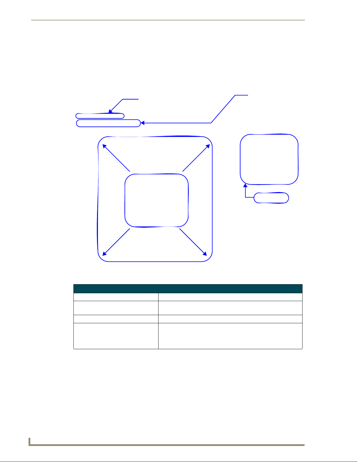
The KeypadBuilder application breaks down as follows:
Menu Bar
KeypadBuilder Project
Navigation Pane
Toolbar
Tasks Pane
FIG. 1 KeypadBuilder Main Window
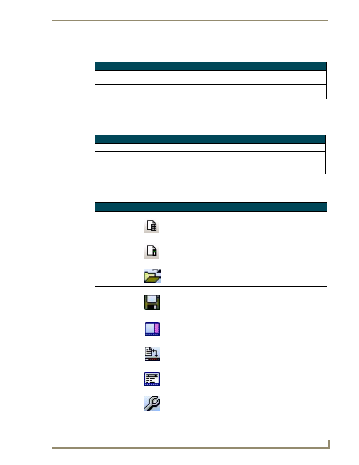
KeypadBuilder Application Interface
Menu Bar Contains the main menu options (File, View, Options and Help).
Tasks Pane Provides a quick link to opening other .KPB files including the Most
Toolbar A button-click option to the most regularly used file tools.
KeypadBuilder Project Navigation Pane When a project is open, a graphic representation of the keypad con-
2
Recently Updated.
figuration is displayed. The tools for designing keypad design are
also available in this pane (Project Properties, Button Configuration,
Engraving, LCD Configuration, Fixed-Menu Configuration).
KeypadBuilder v2.1
Page 15
KeypadBuilder Overview
File Menu
The File menu serves as a location for file management.
File Menu
New Project • Mio Modero Keypad - Launches a new keypad project.
• Mio Modero-R1 - Launches a new remote project.
Launches the New Project dialog window. This will open a new keypad
device project into the KeypadBuilder Project Navigation Pane.
Open Project Launches the Open Project dialog window. Opens a saved .KPB file into the
KeypadBuilder Project Navigation Pane
Close Project Closes the project currently open. An option to save will occur if the file has
not recently been saved.
Open Exported DXF File Launches the Viewing Exported DXF window, this window is a representa-
tion of the DXF created by KeypadBuilder. It is useful to ensure your engraving file is exactly as you had envisioned it.
Save Saves the current project. If the project has not been previously saved it will
Save As Launches the Save As dialog window. This feature allows you to make new
The Most Recently Updated List A list of most recently opened KeypadBuilder files.
Exit Closes the KeypadBuilder application.
launch the Save As dialog window.
revision files.
View Menu
Contains options for configuring the KeypadBuilder work area.
View Menu
Toolbar Toggles the toolbar in and out of view.
Tasks Pane Toggles the tasks pane in and out of view.
Visual Styles Mouse-over to open the visual style sub-menu. The visual style is the look and
feel of the KeypadBuilder application. The styles emulate Windows themes:
• Default
•Office XP ®
• Office 2003 ®
• Windows XP ® Theme
Options Menu
The Options menu allows you to set application features and generate file reports.
Options Menu
Preferences... Launches the Preferences dialog. Preferences sets the default device features, project
view options and the number of files in the most recently updated files list.
KeypadBuilder v2.1
3
Page 16
KeypadBuilder Overview
Help Menu
The Help menu contains features for updating the application and information on how to use
KeypadBuilder.
Help Menu
Help Launches the KeypadBuilder help file.
Web Update... Launches the AMX Web Update utility. Internet connection is necessary.
About KeypadBuilder... Displays the about KeypadBuilder dialog containing information pertaining to version
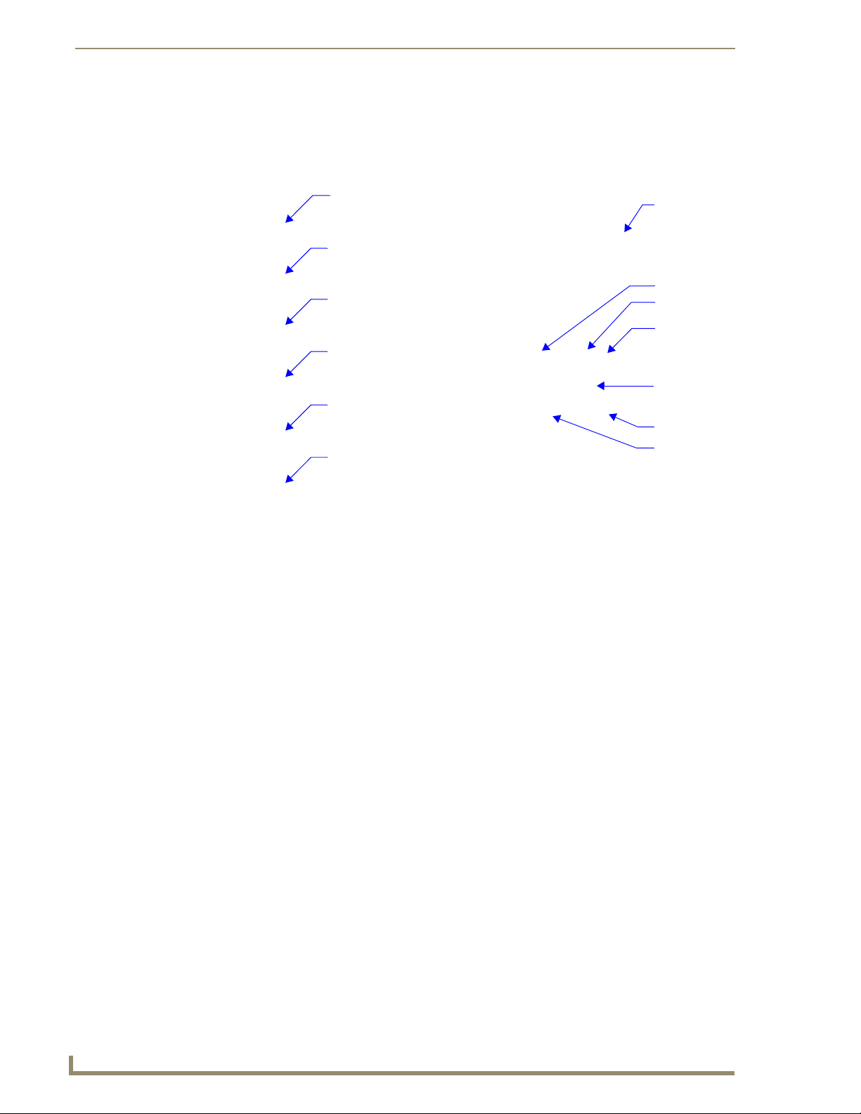
Toolbar
The toolbar contains button shortcuts for the commonly used functions:
Toolbar
New Keypad Launches a new keypad project.
New Remote Launches a new remote project.
and copyright.
Open Project Launches the Open Project dialog window.
Tasks Pane Toggles the tasks pane in and out of view. Only available when a project is
User Preferences Launches the Preferences dialog window.
not currently open.
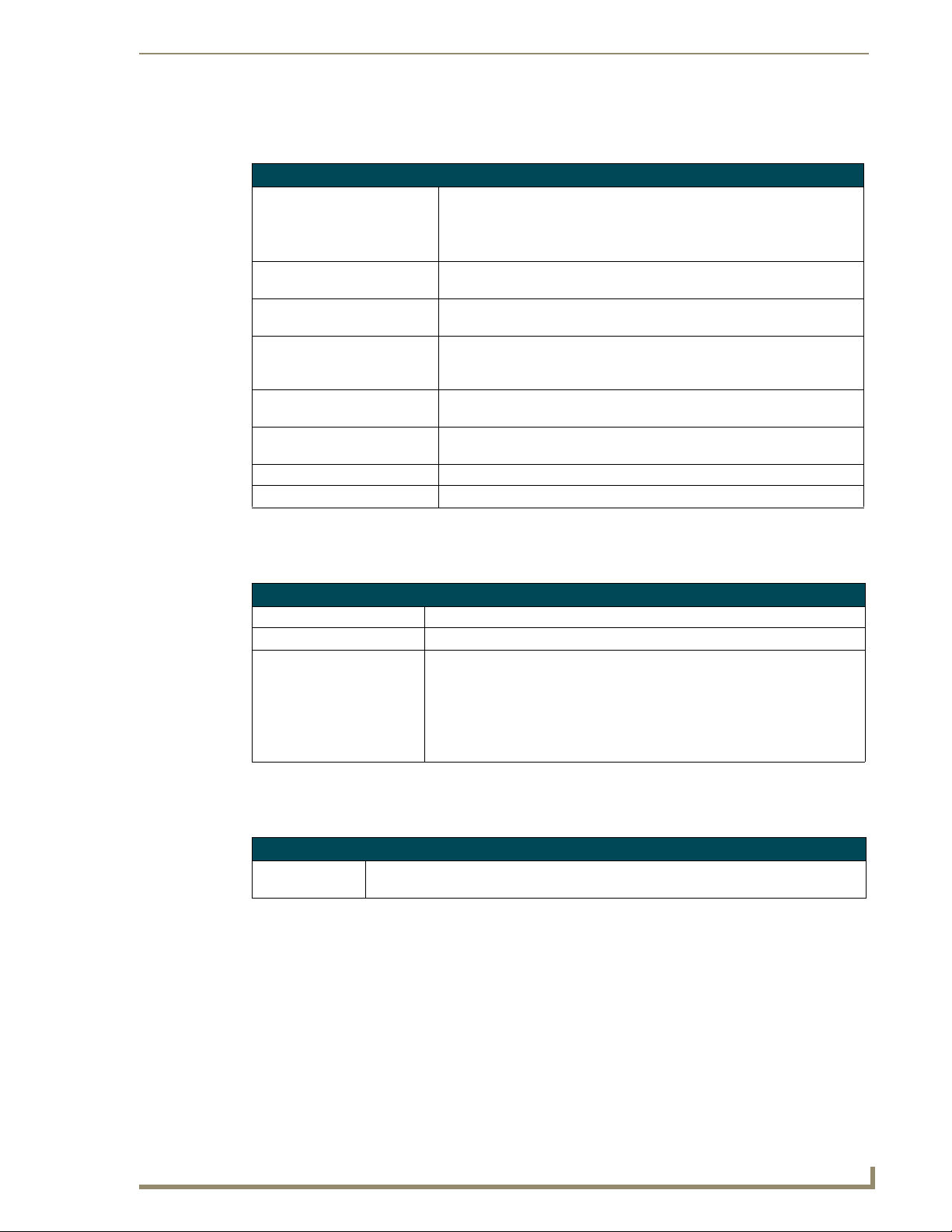
Tasks Pane
The Tasks Pane is s list of most recently updated KeypadBuilder files and a quick link to starting new
KeypadBuilder projects. Additionally, you can open other KeypadBuilder files by clicking More
Documents to launch the Open KeypadBuilder Project dialog window.
FIG. 2
KeypadBuilder Tasks Pane
You can start a new project by clicking New Mio Modero Keypad to start a new Mio Modero project or
select New Mio Modero-R1 to start a new remote project.
4
KeypadBuilder v2.1
Page 17

KeypadBuilder Overview
Installing MS Arial Unicode
Arial Unicode MS font is a full Unicode font. Unicode is a character encoding standard developed by the
Unicode Consortium. By using more than one byte to represent each character, Unicode enables almost
all of the written languages in the world to be represented by using a single character set. It contains all
of the characters, ideographs, and symbols defined in the Unicode 2.1 standard.
In Microsoft Windows 2000
Quit all programs.
1.
2. In Control Panel, double-click the Add/Remove Programs icon.
3. Do one of the following:
If you installed your Microsoft Office program as part of an Office package, click Microsoft
Office in the Currently installed programs box, and then click Change.
If you installed your Office program individually, click the name of your program in the
Currently installed programs box, and then click Change.
4. In the Microsoft Office 2003 Setup dialog box, click Add or Remove Features, and then click
Next.
5. Select Choose advance customization of applications, and then click Next.
6. Next to Office Shared Features, click the plus sign (+).
7. Next to International Support, click the plus sign (+).
8. Click the icon next to Universal Font, and then select the installation option you want.
KeypadBuilder v2.1
5
Page 18

KeypadBuilder Overview
6
KeypadBuilder v2.1
Page 19

Basic Operations
Accessing A File via The Most Recently Updated List
KeypadBuilder has the option of tracking a set number of Most Recently Updated files. To open one of
these files, go to the File Menu and select the .KPB file from the list. The file opens in the Navigation
Pane.
Accessing KeypadBuilder Help
KeypadBuilder is context sensitive; hit the F1 key on your keyboard to view the help topic for the active
area of KeypadBuilder. Otherwise, go to Help > Help to view the entire help file.
Closing A Project
To close a KeypadBuilder file currently open in the Navigation Pane, go to File > Close. If you have
made unsaved changes to your file, you are prompted to save them at this time.
Exiting The KeypadBuilder Application
To exit the KeypadBuilder application, go to File > Exit. If you have made unsaved changes to your file,
you are prompted to save them at this time.
Basic Operations
Generating A Project Report
To view a detailed list of your KeypadBuilder project file, go to Options > Generate Report. This
launches the Project Report dialog window.
Opening An Existing Project
To work with a previously saved KeypadBuilder file, go to File > Open and select the saved
KeypadBuilder file.
Saving A Project File
To save a KeypadBuilder file currently open in the Navigation Pane, go to File > Save. If you have not
previously saved the file, you are prompted with the Save As dialog where you must designate the file
name and location.
KeypadBuilder v2.1
7
Page 20

Basic Operations
Sending A Configuration File to A Device
To send the final configuration file to you master:
1. Go to Transfer > Send to Device.... This launches the Send Configuration Files dialog window.
2. Click Communication Settings... to confirm your settings are correct.
3. Enter the Device ID.
4. Under Send File Options, make sure Configuration File is checked. If you set the LCD Display
Resolutions in the LCD Configuration module to CJK fonts and this is your first file send, make sure
Font File is checked in the Send File Options.
5. Click Send File. The Transfer Status is displayed below.
6. Upon successful transmission, click Done.
Sending an inappropriate configuration file, i.e., a double-style sent to a single-style,
to a device will result in an overwrite of any file currently residing on the device, but
the device will not work.
Setting KeypadBuilder Application Preferences
Go to Options > Preferences to launch the Preferences dialog window.
To set the Default device for new projects, select the device from the drop down menu.
Select the color for the default device in the Color Selection drop down menu.
To toggle items in and out of view of the Navigation Pane, place a check next to each value
you want displayed on the buttons.
Under General in the Recent File List Size, type the number of most recently updated files you
KeypadBuilder to track; the maximum is 9.
Toggling View Menu Items
The KeypadBuilder application area has items that are added or removed from view. To add or remove
either the Toolbar or Tasks Pane, go to View > Toolbar/Tasks Pane. A check next to the item indicates
the it is active.
Using Web Updates
The AMX WebUpdate program is a stand-alone application that communicates with the AMX website,
allows a user to select from a list of available AMX Software programs to choose for updating,
determines the latest version of the selected applications, returns a listing of available updates, allows a
user to download the selected installation files, and upon request, launches the installation of those
downloads.
The WebUpdate application is not installed by KeypadBuilder, and must be installed
separately. If not found, KeypadBuilder prompts you to download the application from
www.amx.com.
Select Help > Web Update to launch this application.
Refer to the WebUpdate on-line help for details and instructions.
8
KeypadBuilder v2.1
Page 21
The Mio Modero KeypadBuilder Work Area
The Mio Modero KeypadBuilder Work Area
Use KeypadBuilder to create files (*.KPB) that allow you to get the most out of Mio Modero keypads
and the devices they control.
KeypadBuilder Application Interface
The KeypadBuilder application breaks down as follows:
KeypadBuilder Application Interface
Menu Bar Contains the main menu options (File, Edit, View, Navigation, Trans-
Tasks Pane Provides a quick link to opening other .KPB files including the Most
Toolbar A button-click option to the most regularly used file tools.
KeypadBuilder Project Navigation Pane When a project is open, a graphic representation of the keypad con-
File Menu
fer, Options and Help).
Recently Updated.
figuration is displayed. The tools for designing keypad design are
also available in this pane (Project Properties, Button Configuration,
Engraving, LCD Configuration, Fixed-Menu Configuration).
The File menu serves as a location for file management.
File Menu
New Project • Mio Modero Keypad - Launches a new keypad project.
• Mio Modero-R1 - Launches a new remote project.
Launches the New Project dialog window. This will open a new keypad
device project into the KeypadBuilder Project Navigation Pane.
Open Project Launches the Open Project dialog window. Opens a saved .KPB file into the
KeypadBuilder Project Navigation Pane
Close Project Closes the project currently open. An option to save will occur if the file has
not recently been saved.
Open Exported DXF File Launches the Viewing Exported DXF window, this window is a representa-
tion of the DXF created by KeypadBuilder. It is useful to ensure your engraving file is exactly as you had envisioned it.
Save Saves the current project. If the project has not been previously saved it will
Save As Launches the Save As dialog window. This feature allows you to make new
The Most Recently Updated List A list of most recently opened KeypadBuilder files.
Exit Closes the KeypadBuilder application.
launch the Save As dialog window.
revision files.
KeypadBuilder v2.1
9
Page 22
The Mio Modero KeypadBuilder Work Area
View Menu
Contains options for configuring the KeypadBuilder work area.
View Menu
Toolbar Toggles the toolbar in and out of view.
Tasks Pane Toggles the tasks pane in and out of view.
Visual Styles Mouse-over to open the visual style sub-menu. The visual style is the look and
Navigation Menu
Only available when a .KPB file is open, this menu is the crux of adding functionality to the keypad
device. While viewing a graphic representation of your selected keypad device, you can do the
following:
Navigation Menu
Project Configuration... Opens the Project Configuration dialog window. This is topical Project Informa-
Button Configuration... Opens the Button Configuration dialog window. Click to select buttons, and
Engraving... Opens the Engraving dialog window. Click to select buttons and create either
LCD Configuration... For keypad devices equipped with an LCD, the LCD Configuration dialog win-
Fixed Menu System... For keypad devices equipped with an LCD, the Fixed Menu Configuration dia-
Complex-Script Glyphs Launches the Add/Edit Keypad Glyphs dialog window. Create glyph renderings
feel of the KeypadBuilder application. The styles emulate Windows themes:
• Default
•Office XP ®
• Office 2003 ®
• Windows XP ® Theme
tion, Device Selection and Device Setup Information.
then assign button properties, Configuration Options and Display Options. The
Channel Map can be accessed from this dialog.
text or icon engraving instructions. The engraving dialog develops a .DXF file
that must be provided to AMX to create your custom engraved buttons. Keypad
display options and export options are also available in this dialog.
dow sets up Display Options, the presence of Dynamic Text, and Line Options.
log window allows for the creation of Menu and one tier of sub-menus. The
Main Menu can contain a maximum of 10 items. You can edit and add menu
and sub-menu items.
of text and characters for menu/sub-menu items.
10
Transfer Menu
The Transfer Menu enables KeypadBuilder to send and receive configuration files.
Transfer Menu
Send to Device... Opens the Send Configuration Files dialog window. This function allows you to
send both the configuration file and the font file to the keypad device.
KeypadBuilder v2.1
Page 23
The Mio Modero KeypadBuilder Work Area
Options Menu
The Options Menu allows you to set application features and generate file reports.
Options Menu
Generate Report... Launches the Generate Project Report dialog. The Project Report is a detailed list of
every configuration model except Engraving.
Preferences... Launches the Preferences dialog. Preferences sets the default device features, project
view options and the number of files in the most recently updated files list.
Help Menu
The Help menu contains features for updating the application and information on how to use
KeypadBuilder.
Help Menu
Help Launches the KeypadBuilder help file.
Web Update... Launches the AMX Web Update utility. Internet connection is necessary.
About KeypadBuilder... Displays the about KeypadBuilder dialog containing information pertaining to version
and copyright.
Toolbar
The toolbar contains button shortcuts for the commonly used functions:
Toolbar
New Keypad Launches a new keypad project.
New Remote Launches a new remote project.
Open Project Launches the Open Project dialog window.
Save Saves the current project. If the project has not been previously saved it
will launch the Save As dialog window.
Tasks Pane Toggles the tasks pane in and out of view. Only available when a project is
not currently open.
File Transfer Launches the File Transfer dialog window. Only available when a project is
open.
KeypadBuilder v2.1
Generate Report Launches the Generate Project Report dialog window. Only available
when a project is open.
User Preferences Launches the Preferences dialog window.
11
Page 24
The Mio Modero KeypadBuilder Work Area
KeypadBuilder Project Navigation Pane
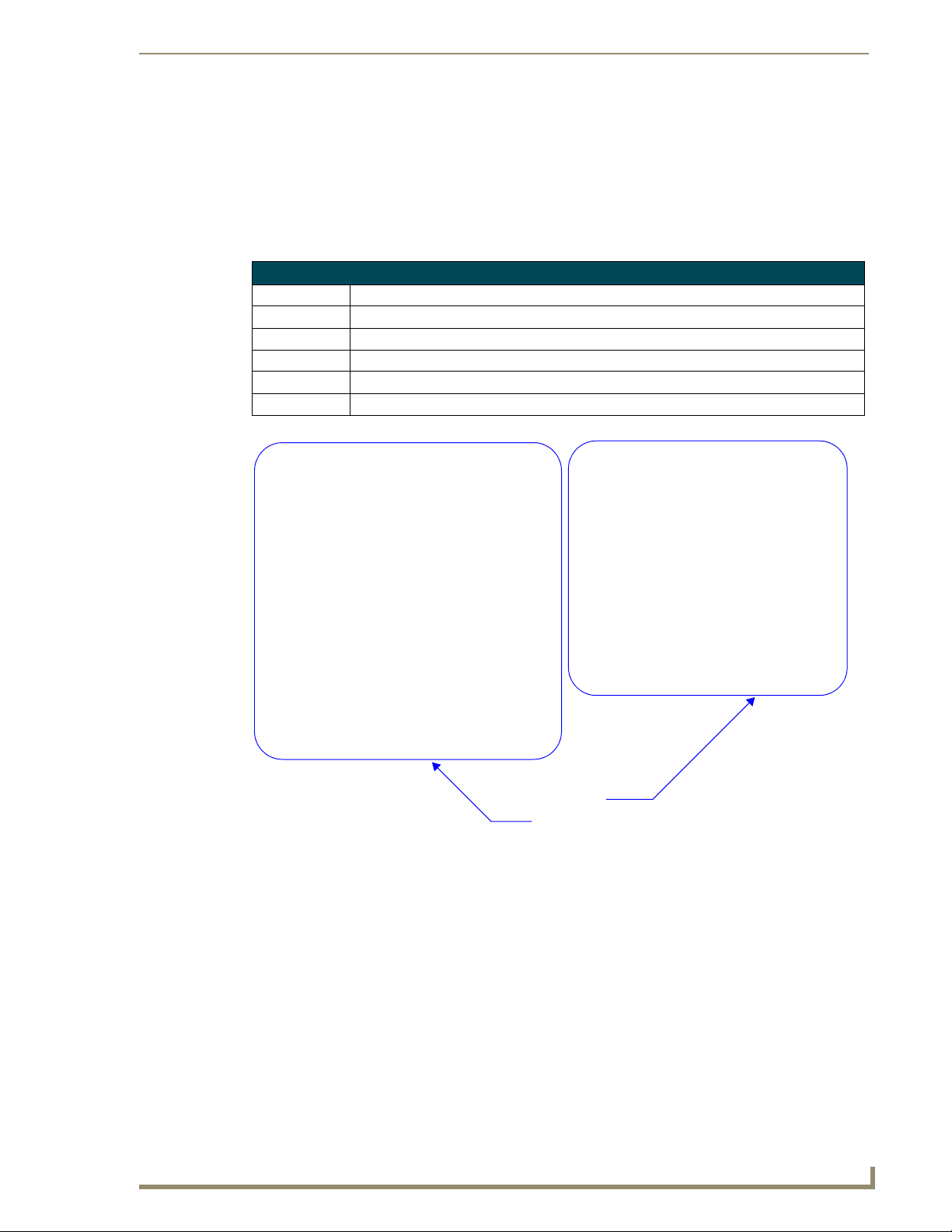
The KeypadBuilder Project Navigation Pane is open when a project file is active. This is the main area
for accessing the configuration modules in creating a keypad device file.
Project Properties
Configuration
Module
Button Configuration
Module
Graphic
representation
of your
keypad device
Engraving Configuration
Module
LCD Configuration
Module
Fixed-Menu
Configuration
Module
Complex-Script
Glyphs Module
FIG. 3 KeypadBuilder Project Navigation Pane
Button Number
The Channel for
this button is
locked
Channel assigned
to this button
Engraving
information
Menu Action
Button Name
12
KeypadBuilder v2.1
Page 25
Mio Modero Configuration Modules
Mio Modero Configuration Modules
Project Properties
The Project Properties module is Project Information, information to make the file unique and Device
Selection, the type of keypad device to be programmed.
Project Information
Project Name The name of the keypad device project. This field is user defined and optional.
Designer The designer name creating the KeypadBuilder file. This field is user defined and optional.
Dealer Dealer name providing the keypad file. This field is user defined and optional.
Purchase Order This name will populate the file name of the .DXF in the engraving section.
Sales Order This name will populate the file name of the .DXF in the engraving section.
Comments Any additional comments or clarifications for the file. This field is user defined and optional.
KeypadBuilder v2.1
Project Properties Dialog Window
FIG. 4
Device Selection
Project Information
13
Page 26
Mio Modero Configuration Modules
Device Selection
The Device Selection section contains a drop down list of all keypad devices capable of being
programmed by KeypadBuilder. Select the keypad device you wish to design for, and the device appears
in the window below. Assign the keypad device’s color at this time in the drop down list for Color
Selection; the type of device will dictate what colors you can pick.
Changing the device selection clears any previous unsaved work.
Click OK to keep changes and exit the Project Properties module; otherwise, click Cancel and lose the
changes.
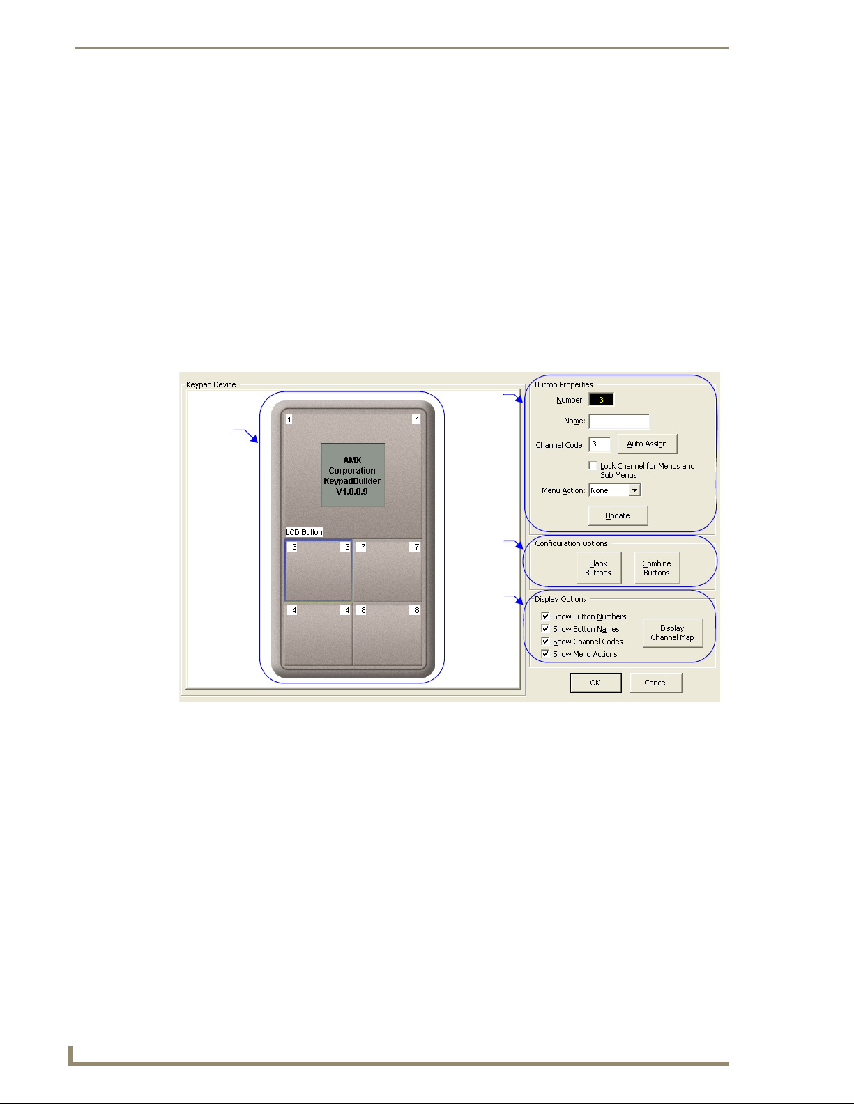
Button Configuration
The Button Configuration module allows you to set the keypad button properties.
Graphic
interface
for keyp ad
device
Button
Properties
Configuration
Options
Display
Options
FIG. 5 Button Configuration Dialog Window
Keypad Device
The Keypad Device area is a graphic representation of your keypad device. Click on a button to select
and assign properties.
14
KeypadBuilder v2.1
Page 27
Mio Modero Configuration Modules
Button Properties
The button properties are as follows:
Button Properties
Number This number is dictated by the selected device’s firmware and is intended to assist in
navigating the keypad device file.
Name The button name is for use within KeypadBuilder only and is intended to assist in
developing unique names.
Channel Code The channel code represents communication out of the panel to the master control-
ler. By default the channel code is the same as the button number. Clicking Auto
Assign takes the next unassigned channel code.
Lock Channel Code for
Menus and Sub Menus
Menu Action This option only applies to devices equipped with a displays. Assign a button to exe-
Update Confirms all changes and channel assignments for the selected button.
Placing a check in the box locks the selected channel code and prevents it from
being assigned in any other menu or sub menu.
cute one of the following:
• Up - Navigate up the menu items.
• Down - Navigate down the menu items.
• Select - Activates the menu selection. The selection can lead to a sub menu or a
channel code activation.
• Home - This button assignment will return the display menu to the top level.
• None - The button has no interaction with the menu system.
Configuration Options
Blank Buttons - Blank buttons contain no channel code assignment. It is important to assign
blank buttons before the engraving process as they are included in the order.
Combine Buttons - Click Combine Buttons to activate and deactivate. When in combine
button mode, click on a button you wish to combine. Always select the left of the two button
you wish to combine. Combine Buttons takes the button information from the selected button
and assigns it to the button directly to the right of it, thus treating two buttons as one. To
uncombine a button, select the button again. The button on the right retains no information.
Combining buttons adds double buttons to your custom engraving order.
Display Channel Map
Click Display Channel Map to view a listing of channel codes that have already been assigned within
your active KeypadBuilder file.
Click on any channel code number to see its current allocation.
Channel Information
Channel Code The assigned channel code number.
Assigned To If used, the item and description of the button using the channel code.
KeypadBuilder v2.1
15
Page 28
Mio Modero Configuration Modules
Display Options
These display options are for use within the Button Configuration window. Placing a check in any box
activates its display.
Display Options
Show Button Numbers Displays all button numbers.
Show Button Names Displays the button name if set.
Show Channel Codes Displays set channel codes for the keypad device.
Show Menu Actions Displays the menu action value for the button.
Click OK to keep changes and exit the Button Configuration module; otherwise, click Cancel and lose
the changes.
Engraving
The Engraving module allows you to create the .DXF file that AMX needs to create your device’s
custom keypad.
Graphic
interface
for keyp ad
device
Button
configuration
information
Tex t
engraving
information
Display
Options
DXF export options
Engraving Dialog
FIG. 6
Keypad Device
The Keypad Device area is a graphic representation of your keypad device. Click on a button to select
and assign properties.
16
KeypadBuilder v2.1
Page 29
Mio Modero Configuration Modules
Text Engraving
The engraving information and options are as follow:
Text Engraving
Number This number is dictated by the selected device’s firmware and is intended to assist in navigat-
ing the keypad device file.
Name The button name is for use within KeypadBuilder only and is intended to assist in developing
unique names. The name is established in the Button Configuration module.
Menu Action If a menu action is assigned in the Button Configuration module, the action is displayed in this
field; otherwise, it is blank.
Text This is either the text or icon set to display on the button. The text is dictated by the font
selection. If you select Icon in the font selection, you could use letters to get the associated
icon but the Symbols drop down list is a simpler approach. There is a limit of 10 characters per
button.
Symbols The Symbols drop down list is available when you select AMX Icon in the font selection list.
The list is a collection of icons created by AMX. When you select an icon the corresponding
letter is placed in the Te xt field. If you select more than one icon it will not replace the previous
icon, but rather add it and display all selected icons.
Font Selection A drop down list of fonts supported by KeypadBuilder for use in engraving the buttons. Icons
Scale A ratio ranging from 0.5 to 1.5. The larger the ratio, the more area of the button the text or icon
Note: If your font selection or scale is greater than the area of the button that can be engraved, you will
receive a warning in this field and KeypadBuilder will not create the .DXF file.
Update Confirms changes to the button engraving.
must be selected to use the Symbols drop down list.
fills.
Display Options
These display options are for use within the Engraving window. Placing a check in any box activates its
display.
Display Options
Show Button Numbers Displays all button numbers.
Show Button Names Displays the button name if set.
Show Menu Actions Displays the menu action value for the button.
Show Channel Codes Displays set channel codes for the keypad device.
Show Bounding Box Displays the surface area of the button you can engrave.
Export to DXF File
KeypadBuilder creates the .DXF file that is applied to a jig in the engraving machine.
Export to DXF File
Export File... Opens the Export DXF File dialog window. This creates the .DXF file neces-
sary for engraving.
Preview... Opens the Engraving Template Preview dialog window. This is a graphic repre-
sentation of the jig used in engraving.
Click OK to keep changes and exit the Engraving module; otherwise, click Cancel and lose the changes.
KeypadBuilder v2.1
17
Page 30
Mio Modero Configuration Modules
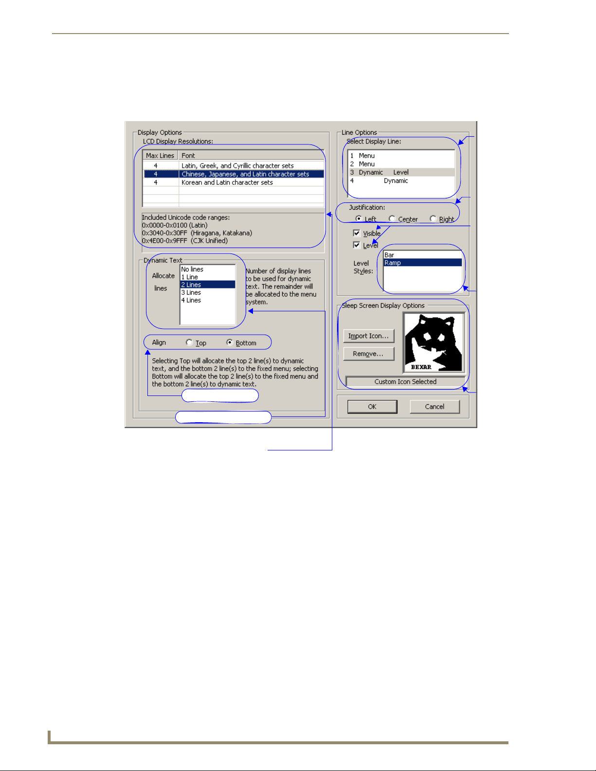
LCD Configuration
The LCD Configuration module controls what menu items are shown and how they are displayed in
devices equipped with an LCD.
Display
line
selection
Line display
justification
Dynamic
line
visibility
and level
assignment
Dynamic
line level
style
Sleep
Screen
Dynamic line alignment
Dynamic text line allocation
LCD Display; number of lines and font type
Display
Options
FIG. 7 LCD Configuration Dialog Window
LCD Display Resolution
The Display Resolution is the maximum number of lines and type of font family that can be displayed at
one time on your selected device. Click on a font family to select. Only one font family can be used on a
device. If you change the font, you need to include the font information when sending the configuration
file. See the Send Configuration Files dialog window section on page 81.
Dynamic Text
Dynamic Text is information sent from the master and displayed on the device, i.e., time or temperature.
Selecting No Lines for line allocation will cause the device to have lines of displayed menu (text) and no
dynamic information. All lines can be allocated for either menu or dynamic. Regardless of the display
arrangement, the items must be contiguous; the menu items and dynamic items must be grouped
together.
Align
The align feature allows you to decide which, menu or dynamic, items are displayed first. Top places the
dynamic items at the top of the list and Bottom puts them at the bottom.
18
KeypadBuilder v2.1
Page 31

Mio Modero Configuration Modules
Select Display Line
Select one of display lines and based on its type, dynamic of menu, set the following attributes:
Justification - The display item appears in the LCD as either Left aligned, Center aligned, or
Right aligned. This feature works for both dynamic and menu items.
Visible - A check in the box means the display item appears in the LCD. This feature is only
available for dynamic items.
Level - A check in the box means the display item is feedback option. This feature is only
available for dynamic items.
Level Styles - When the Level box is checked the display can be on of the styles
listed. Click on one to select.
Sleep Screen Display Options
The Sleep Screen Display is an optional graphic you can set to display on the LCD when the device is
not in use.
Basic graphic formats are supported, .bmp, .png, and .jpg. The resolution can be no bigger than 96 x 96,
items smaller than that resolution are centered. Images must be monochrome.
Import Icon... - Opens the Import Splash Screen Icon File dialog window. This selects the
image for display in the LCD.
Remove... - Asks for confirmation to delete the currently used Splash Screen Image.
Click OK to keep changes and exit the LCD Configuration module; otherwise, click Cancel and lose the
changes.
KeypadBuilder v2.1
19
Page 32

Mio Modero Configuration Modules
Fixed-Menu Configuration
The Fixed-Menu Configuration module allows you to create the navigation hierarchy for you keypad
device.
Fixed Menu Edit
After the LCD display has been configured, you can set the menu items for navigating the device.
Remember to include menu navigation buttons in the Button Configuration section on page 14 if your
number of menu items exceeds the number of lines displayed in the LCD.
Fixed Menu Edit
Main Menu The main menu is the top level navigation for display. There is a maximum of 10 main menu
Sub Menu The sub menu is the next level of navigation under the main menu. There is a maximum of
Menu Type The selected menu or sub menu is either Text (the basic single-byte ANSI character set),
Channel The assigned channel of either the menu or sub menu selected.
Up Moves the selected menu item up in increments of one line in the order of display.
Down Moves the selected menu item down in increments of one line in the order of display.
Add Item Opens the Add/Edit Menu Item window. Add menu and sub menu items through this win-
Delete/Undelete Select a menu item and click Delete; removes a menu or sub menu item from display. Once
Edit Opens the Edit Keypad Menu window. Edit menu properties and channel assignments for
Channel Map Click Channel Map to view a listing of channel codes that have already been assigned
Close Closes the Fixed-Menu Configuration module. There is no cancel and the changes are kept.
items. Neither the first nor the last menu item can be a separator item.
• Edit Menu Properties - Either double click on Edit Menu Properties or select it and click
Edit, doing so opens the Edit Keypad Menu window. Edit menu properties and channel
assignments for the keypad menu. These functions are also addressed in the Button
Configuration section on page 14. You can set the menu properties to either Text,
Unicode, or Complex Script.
• Add Menu Item - Either double click on Add Menu Item or select it and click Add Item,
doing so opens the Add/Edit Menu Item window. Add menu items through this window.
The menu properties determines the type of menu item you can add.
10 sub menu items. Neither the first nor the last sub menu item can be a separator item.
• Edit Sub-Menu Properties - Either double click on Edit Sub-Menu Properties or select it
and click Edit, doing so opens the Edit Keypad Menu window. Edit sub menu properties
and channel assignments for the keypad menu. You can set the sub menu properties to
either Text, Unicode, or Complex Script.
• Add Sub-Menu Item - Either double click on Add Sub-Menu Item or select it and click Add
Item, doing so opens the Add/Edit Menu Item window. Add sub menu items through this
window. The sub menu properties determines the type of menu item you can add.
Unicode (multi-byte character representation), or Complex Script (a graphic rendering of
any type face character entered). This is the menu text displayed within the LCD.
dow.
deleted it is indicated with (DELETED) next to the affected item. To undelete, select the
menu item and click Undelete. Deleted items are not sent to the device and are
permanently removed upon saving the file.
the keypad menu and sub menus.
within your active KeypadBuilder file.
Click on any channel code number to see its current allocation.
20
KeypadBuilder v2.1
Page 33

Main menu items
FIG. 8 Fixed Menu Edit Dialog Window
Sub menu items
for selected
main menu item
Move
menu
item up
Move
menu
item
down
Mio Modero Configuration Modules
Menu type;
either text
or Unicode
Channel
assignment
for selected
menu or
sub menu
Add item to
selected menu
Delete the
selected menu
item
Edit selected menu proper ties
Launch Channel Map
Edit Keypad Menu window
The Edit Keypad Menu window is the same arrangement for both Menu and Sub Menu items.
Edit Keypad Menu Window
Menu Type Click the radio button for either Text, Unicode, or Complex Script. This is the method by which
Button The number for the button currently selected in the Menu Channel Map graphic. Beneath the
Channel Channel assignment for selected menu or sub menu item
Auto Assign Takes the next unassigned channel code.
Channel Map Click Channel Map to view a listing of channel codes that have already been assigned within
OK Confirms changes and closes the window.
Cancel Clears changes and closes the window.
KeypadBuilder displays your menu items within the LCD.
Note: A menu type can only be switched if there are no menu items present, and this is true for
sub menus too.
button number is a list of active button number and their names.
your active KeypadBuilder file.
Click on any channel code number to see its current allocation.
KeypadBuilder v2.1
21
Page 34

Mio Modero Configuration Modules
Menu Type display items are either Text, Unicode or Complex Script
Button number; button is selected either through the graphic or list.
Button channel assignment. This button cannot be changed because the channel was locked.
FIG. 9 Edit Keypad Menu Dialog Window
22
KeypadBuilder v2.1
Page 35

Mio Modero Configuration Modules
Add and Edit Menu Item window
The following options apply to keypad menu items that have been designated as the menu type, Te xt .
Add and Edit Menu Item (Text)
Item Caption The name displayed for either the menu or sub menu item.
Has Sub-Menu (only active in
main menu items)
Separator A blank line between items. This line counts as one of the device’s allocated
Select Active (only active in
main menu items)
Return to Main After menu or sub menu item is selected, the display returns to the device’s
Channel Code The assigned channel of either the menu or sub menu selected. Either type a
Auto Assign Takes the next unassigned channel code.
Channel Map Click Channel Map to view a listing of channel codes that have already been
OK Confirms changes and closes the window.
Cancel Clears changes and closes the window.
Assigns a sub menu to the selected menu item.
display lines.
Navigating and releasing on a menu item is the only necessary action to make
it active; there is no need for a select button.
main menu.
channel code in, click the up and down arrows or click Auto Assign to enter a
channel code.
assigned within your active KeypadBuilder file.
Click on any channel code number to see its current allocation.
FIG. 10
Menu item display name
Menu item attributes
Menu item channel code assignment
Add and Edit Menu Item (Text)
KeypadBuilder v2.1
23
Page 36

Mio Modero Configuration Modules
The following options apply to keypad menu items that have been designated as the menu type, Unicode.
Add and Edit Menu Item (Unicode)
Menu Caption The name displayed for either the menu or sub-menu.
Unicode Character Codes The Unicode translation for the text assigned to the menu or sub menu.
Has Sub-Menu (only active in
main menu items)
Separator A blank line between items. This line counts as one of the device’s allocated
Select Active (only active in
main menu items)
Return to Main After menu or sub menu item is selected, the display returns to the device’s
Channel Code The assigned channel of either the menu or sub menu selected. Either type a
Auto Assign Takes the next unassigned channel code.
Channel Map Click Channel Map to view a listing of channel codes that have already been
OK Confirms changes and closes the window.
Cancel Clears changes and closes the window.
Assigns a sub menu to the selected menu item.
display lines.
Navigating and releasing on a menu item is the only necessary action to make
it active; there is no need for a select button.
main menu.
channel code in, click the up and down arrows or click Auto Assign to enter a
channel code.
assigned within your active KeypadBuilder file.
Click on any channel code number to see its current allocation.
FIG. 11
Add and Edit Menu Item (Unicode)
Menu item display name in Unicode
Unicode points associated to menu display
name; characters are separated by pipes
Menu item attributes
Menu item channel code assignment
24
KeypadBuilder v2.1
Page 37

Mio Modero Configuration Modules
The following options apply to keypad menu items that have been designated as the menu type, Complex
Script.
Add and Edit Menu Item (Complex Script)
Glyph Name The name associated with the glyph. This is for tracking purposes only and is
not displayed within the LCD.
Glyph A sample of the graphic as it appears within the LCD.
Glyph ID Number An ID number KeypadBuilder associates with all glyphs within the project to
Item Name The name of the menu or sub menu item. This value only appears in the Fixed-
Has Sub-Menu (only active in
main menu items)
Separator A blank line between items. This line counts as one of the device’s allocated
Select Active (only active in
main menu items)
Return to Main After menu or sub menu item is selected, the display returns to the device’s
Channel Code The assigned channel of either the menu or sub menu selected. Either type a
Auto Assign Takes the next unassigned channel code.
Channel Map Click Channel Map to view a listing of channel codes that have already been
Glyph Select List of available glyphs and their current state. Click on a glyph to select.
OK Confirms changes and closes the window.
Cancel Clears changes and closes the window.
ensure unique values.
Menu Configuration window.
Assigns a sub menu to the selected menu item.
display lines.
Navigating and releasing on a menu item is the only necessary action to make
it active; there is no need for a select button.
main menu.
channel code in, click the up and down arrows or click Auto Assign to enter a
channel code.
assigned within your active KeypadBuilder file.
Click on any channel code number to see its current allocation.
KeypadBuilder v2.1
25
Page 38

Mio Modero Configuration Modules
Glyph name
Glyph
Menu item channel code assignment
FIG. 12 Add and Edit Menu Item (Complex Script)
Glyph Select
Glyph ID number
Item Name
Menu item attributes
Complex-Script Glyphs
The Complex-Script Glyph configuration module allows you to create menu/sub-menu items using
characters and fonts that could not otherwise be displayed. Selecting the Complex-script glyph launches
the Add/Edit Keypad Glyphs dialog window.
What is a Complex-Script Glyph?
A complex-script glyph is a rendering of a group of characters without an application dependency for
font or language support. KeypadBuilder creates a graphic image from predefined text and then load the
graphic to your device. This is useful for rendering conditional script languages, displaying proprietary
fonts on devices and utilizing icon type. The only type limitations are what your computer already has;
you cannot display a language you do not have loaded on your PC. Only the glyph and not the font is
ever loaded on your device.
KeypadBuilder supports the creation of 256 glyphs per device project.
26
KeypadBuilder v2.1
Page 39

Mio Modero Configuration Modules
Add/Edit Keypad Glyphs dialog window
The Add/Edit Keypad Glyphs dialog window allows you to create, edit and manage your menu glyphs.
Add and Edit Keypad Glyphs
Glyph name The name associated with the glyph, this is useful for tracking icon glyphs and multiple
language menu items.
Glyph graphic A thumbnail rendering of the glyph as it displays in the menu.
Glyph selection A list of available glyphs. Click on a glyph to select.
Create new glyph Launches the Create/Modify Glyphs dialog window to create new glyph entries.
Edit existing glyph Launches the Create/Modify Glyphs dialog window to edit existing glyph entries. You must
have a glyph selected in order to edit it.
Delete glyph Toggles a selected glyph from Deleted to not. If you delete a glyph and close the project,
the glyph is gone permanently.
Close Closes the Add/Edit Keypad Glyphs dialog window and enacts changes.
Glyph name
Glyph graphic
Glyph selection
Create new glyph
FIG. 13
Edit existing glyph
Delete glyph
Add and Edit Keypad Glyphs
KeypadBuilder v2.1
27
Page 40

Mio Modero Configuration Modules
Create/Modify Glyphs dialog window
KeypadBuilder supports the creation of glyph characters. The Create/Modify Glyphs dialog window
allows you to generate graphic representatives for unique script languages and also enables the use of
specialty fonts.
Create/Modify Glyphs
Font type information This is a listing of the family and point size of the font you currently have selected.
Character entry field Click in this field to place the cursor, this is where you type your glyph.
Glyph attributes This is the number of characters your glyph occupies and the dimensions in pixels
Format font selection Launches the Windows font format dialog window. Select the family, format and
Clear character entry field Clears all typed information in the character entry field, only the font information
Create Glyph Renders a glyph from the information typed in the character entry field based upon
Rendered glyph The glyph after Create Glyph is selected. This is what will appear as a menu item.
Glyph Name The name associated with the glyph image.
Glyph ID An automatically assigned value (0-255) for index and application tracking pur-
(WxH). The glyph can be no larger than 96x24.
size of the font.
remains.
the font type and character set selection.
poses.
Font type
information
Character entry
field
Clear character
entry field
Glyph attributes
Rendered glyph
FIG. 14
Create/Modify Glyphs
Format font selection
Create Glyph
Glyph Name
Glyph ID
28
KeypadBuilder v2.1
Page 41

Mio Modero Application Operations
Mio Modero Application Operations
Creating A New Project
To create a new KeypadBuilder file, go to File > New Project. The device type that opens depends upon
what is set in the Preferences menu.
Setting The Project Configuration
With a new KeypadBuilder project file open, click Project Properties in the Navigation Pane.
1. Under the Project Information section set the applicable fields:
Project Name - This is user defined. Type the name of your project in this field.
Designer - Type the name of the keypad project designer in this field.
Dealer - Type the name of the Dealer providing the keypad project file.
Project Order - If the keypad project has a project order number, type it in this field.
Sales Order - If the keypad project has a sales order number, type it in this field.
Comments - Any additional comments concerning the project file can be entered in this box.
2. Under the Device Selection section, establish the device that uses the keypad project file. If the
keypad device differs from the default file that opened, select the keypad device from the drop down
menu.
3. Select the color of your keypad device from the drop down list, Color Selection.
4. Click OK to confirm the changes or Cancel to exit and drop all changes.
Setting The Button Configuration
With a new KeypadBuilder project file open, click Button Configuration in the Navigation Pane.
1. By clicking on a button in the Keypad Device area, select a button you wish to configure.
Under Button Properties:
The Number field cannot be edited, it is set by the firmware for the keypad device
selected.
2.
Type the name of the button in the Name field. The button name is useful in tracking channel
assignments. This name should not be confused with what is sent to engraving, this name is strictly
within KeypadBuilder.
3. Enter the Channel Code for the button assignment in the field provided. KeypadBuilder inserts the
next available code if you click Auto Assign.
Placing a check next to Lock Channel for Menus and Sub Menus makes the assigned
channel code unavailable for any other button assignments.
Set the Menu Action value by selecting one from the drop down list. A menu action interacts with
4.
the fixed menu items you can set later.
Up - moves the navigation up through the menu system.
Down - moves the navigation down through the menu system.
Select - activates the navigation item in the menu system.
Home - returns the navigation back to the main menu system.
If you have a menu system, it is a good idea to be aware of possible navigation
issues. When you have more menu line items than what is supported by your device
display, an Up and Down menu action allows you to access them. If you have submenus, you might need a Home menu action to return you to the main menu.
KeypadBuilder v2.1
29
Page 42

Mio Modero Application Operations
5. Click Update to set the values for your selected button. Clicking on another button before clicking
Update will drop all settings for your selected button. Repeat this for all of your buttons including
the LCD button.
6. Set the Configuration Options
To create blank buttons, click Blank Buttons. Now click on any button in the Keypad Device
area to make it a blank. Making a button that previously held information blank drops all
configuration information. Click Blank Buttons again to exit mode.
To combine buttons, click Combine Buttons. Click on any button and it combines with the
button to its immediate right. The button configuration information of the right button is
dropped. Click Combine Buttons again to exit mode.
It is important to set your blank and combined buttons before creating the engraving
file; they are included in the custom order you place with AMX.
7. Click OK to confirm the changes or Cancel to exit and drop all changes.
Creating The Engraving File
With a new KeypadBuilder project file open, click Engraving in the Navigation Pane.
1. By clicking on a button in the Keypad Device area, select a button you wish to engrave.
The Number field cannot be edited, it is set by the firmware for the keypad device
selected.
If you have already set the Button Configuration module, the Name and Menu Action
fields are populated.
2.
In the Font Selection drop down menu, select between placing a symbol, AMX Icon 2, or text, Arial
Unicode MS. There is a maximum of 10 characters per button.
If you selected Arial Unicode MS, type the text you want displayed in the Te xt field.
If you selected AMX Icon 2, the Symbol drop down menu is enabled. Either select the symbol
from the list or type the corresponding keyboard character in the Tex t field. Buttons can have
more than one character.
30
The KeypadBuilder Engraving module supports the engraving of its listed supported
OS languages. You must have the language loaded on you OS and then use Unicode
to render the text on the button.
3. Set the size of either the symbol or text on the button. Click on the Scale drop down menu and select
in a range from 0.5 to 1.5.
4. Click Update.
5. To preview the .DXF file as it appears to the engraver, click Preview...
6. Click Export DXF File... to create the DXF file.
7. Within the Export DXF File dialog window, set the destination directory for the file. Either type or
click Browse to determine where to save the file.
KeypadBuilder v2.1
Page 43
Mio Modero Application Operations
8. Type a Description of the file in the field provided. The description aids in making a unique file
name for the engraver.
The File to Export field displays what the final file name is. For example:
C:\(Media Room)-S12-D0-SB0-DB0-CElite Taupe.DXF
Anatomy of A DFX File
C:\ Destination directory for the .DXF file.
(Media Room) Populated by the Description field.
S12 12 single buttons.
D0 0 double buttons.
SB0 0 single blank buttons.
DB0 0 double blank buttons.
CElite An Elite keypad device.
Taupe The keypad color is taupe.
9.
Click Export to confirm and create the DXF file.
10. Click Done to exit the dialog window.
11. Click OK to save changes to the Engraving module and return to the Navigation Pane.
Setting The LCD Configuration
With a new KeypadBuilder project file open, click LCD Configuration in the Navigation Pane. After
you have set the options you need, click OK.
Display Options
Under LCD Display Resolutions, select the arrangement for your LCD device.
Click on the font family and the number of lines to display on the device menu.
Dynamic Text
If you want to designate any lines as dynamic you must make a selection under Dynamic Text.
Click on the number of lines you want set as dynamic.
Based on the number of lines you select as being dynamic, the rest are allocated to menu items. It is
possible to have either all or no dynamic lines.
If you established dynamic items, select to display the dynamic items at the Top or Bottom under Align.
The display lines cannot alternate between menu and dynamic items.
Click the radio button next to either Top or Bottom.
Line Options
Based on your selection in the Dynamic Text section, the Line Options section could be populated with
all menu items, all dynamic items or a mix of the two.
1. Click on the line number you want to edit.
2. You can change the justification of menu items. Click the radio button to move the item either Left,
Center, or Right.
In addition to justification you can set other values for dynamic items:
Remove the check next to Visible to remove the dynamic item from the display.
Place a check next to Level to make the dynamic display line a level indicator.
If you set the dynamic line as a level, click the Level Style you want to display.
KeypadBuilder v2.1
31
Page 44

Mio Modero Application Operations
Sleep Screen Display Options
You can set the LCD to display an image when not in use or "sleep" mode. The image must be
monochrome and cannot exceed 96 x 96 pixels.
1. Click the Import Icon... button to launch the Import Splash Screen Icon File dialog window.
2. Locate your file and click Open. Below the image reads, "Splash Screen Active."
Setting The Fixed-Menu Configuration
With a new KeypadBuilder project file open, click Fixed-Menu Configuration in the Navigation Pane.
Click Close when you have set all options necessary.
Edit Menu Properties
By default KeypadBuilder is set to create the display items in text. If you plan to use Unicode you must
set it before adding any menu items, the same applies when adding sub menus.
1. In the Fixed Menu Edit dialog window, select Edit Menu Properties in the Main Menu field.
2. Click Edit to launch the Edit Keypad Menu dialog window.
3. Click either the Tex t or Unicode radio button under the Menu Type section. This setting applies to all
menu items.
Under Menu Channel Map notice the Button field is a list of the button numbers with the names you
assigned in the Button Configuration module. The box directly to the right of Button displays the
currently selected button number. You can select buttons by either clicking on them in the Button list or
selecting the button on the graphic keypad device.
If not already set, you can assign channels at this time. You can either:
Type the channel number in the field next to Channel.
Click the UP and DOWN arrows next to the Channel field to navigate through the numbers.
Click Auto As sign and KeypadBuilder will allocate the next available channel.
If you are uncertain as to what channels have been assigned where, click Channel Map to see.
4. Click Update after you make changes to each button.
5. Click OK after you are done.
32
Add a Menu Item (Text)
1.
In the Fixed Menu Edit dialog window, select Add Menu Item in the Main Menu field.
2. Click Add Item to launch the Add/Edit Menu Item dialog window.
3. Type the name of the menu item as it is to display in the LCD in the field Item Caption.
4. Place a check in the boxes of all items that apply:
Has Sub-Menu - Creates an entry beneath this display item.
Separator - This display item has no value and therefore cannot have any other box selections.
This does count as one of your display lines.
Select Active - Item executes upon selection; does not require a select menu action.
Return to Main - The menu returns to the top level after this item has been selected.
5. If this menu item requires a channel assignment either type it or click Auto Assign to have
KeypadBuilder allocate the next available channel.
If you are uncertain as to what channels have been assigned where, click Channel Map to see.
6. Click OK when you are done.
KeypadBuilder v2.1
Page 45

Mio Modero Application Operations
Add a Menu Item (Unicode)
In the Fixed Menu Edit dialog window, select Add Menu Item in the Main Menu field.
1.
2. Click Add Item to launch the Add/Edit Menu Item dialog window.
3. Enter the Unicode text in the Menu Caption field. The corresponding Unicode Send Command
Va l ue is displayed beneath the text box.
4. Click OK to return to the Add/Edit Menu Item dialog window.
5. Place a check in the boxes of all items that apply:
Has Sub-Menu - Creates an entry beneath this display item.
Separator - This display item has no value and therefore cannot have any other box selections.
This does count as one of your display lines.
Select Active - Item executes upon selection; does not require a select menu action.
Return to Main - The menu returns to the top level after this item has been selected.
6. If this menu item requires a channel assignment either type it or click Auto Assign to have
KeypadBuilder allocate the next available channel.
If you are uncertain as to what channels have been assigned where, click Channel Map to see.
7. Click OK when you are done.
Edit Sub-Menu Properties
By default KeypadBuilder is set to create the display items in text. If you plan to use Unicode you must
set it before adding any sub-menu items. You can only edit and add sub-menu properties when they have
been assigned to menu items.
1. In the Fixed Menu Edit dialog window, select a main menu item that has a sub-menu.
2. Edit Sub-Menu Properties in the Sub Menu field.
3. Click Edit to launch the Edit Keypad Menu dialog window.
4. Click either the Tex t or Unicode radio button under the Menu Type section. This setting applies to all
sub-menu items.
Under Menu Channel Map notice the Button field is a list of the button numbers with the names you
assigned in the Button Configuration module. The box directly to the right of Button displays the
currently selected button number. You can select buttons by either clicking on them in the Button list or
selecting the button on the graphic keypad device.
If the buttons are not locked to a particular channel, you can assign channels at this time. These channel
assignments only apply when you have selected the menu item. You can either:
Type the channel number in the field next to Channel.
Click the UP and DOWN arrows next to the Channel field to navigate through the numbers.
Click Auto As sign and KeypadBuilder will allocate the next available channel.
If you are uncertain as to what channels have been assigned where, click Channel Map to see.
5. Click Update after you make changes to each button.
6. Click OK after you are done.
KeypadBuilder v2.1
33
Page 46

Mio Modero Application Operations
Add a Sub-Menu Item (Text)
In the Fixed Menu Edit dialog window, select Add Sub-Menu Item in the Sub Menu field.
1.
2. Click Add Item to launch the Add/Edit Menu Item dialog window.
3. Type the name of the menu item as it is to display in the LCD in the field Item Caption.
4. Place a check in the boxes of all items that apply:
Separator - This display item has no value and therefore cannot have any other box selections.
This does count as one of your display lines.
Return to Main - The menu returns to the top level after this item has been selected.
5. If this sub-menu item requires a channel assignment either type it or click Auto Assign to have
KeypadBuilder allocate the next available channel.
If you are uncertain as to what channels have been assigned where, click Channel Map to see.
6. Click OK when you are done.
Add a Sub-Menu Item (Unicode)
In the Fixed Menu Edit dialog window, select Add Sub-Menu Item in the Sub Menu field.
1.
2. Click Add Item to launch the Add/Edit Menu Item dialog window.
3. Enter the Unicode text in the Menu Caption field. The corresponding Unicode Send Command
Va l ue is displayed beneath the text box.
4. Click OK to return to the Add/Edit Menu Item dialog window.
5. Place a check in the boxes of all items that apply:
Separator - This display item has no value and therefore cannot have any other box selections.
This does count as one of your display lines.
Return to Main - The menu returns to the top level after this item has been selected.
6. If this sub menu item requires a channel assignment either type it or click Auto Assign to have
KeypadBuilder allocate the next available channel.
If you are uncertain as to what channels have been assigned where, click Channel Map to see.
7. Click OK when you are done.
Arranging Menu and Sub Menu items
In both the Main and Sub Menu fields, the items are appear top to bottom as they do in the LCD.
To move an item:
1. Select the menu item from the list.
2. Click either Up or Down to move the item within the list.
To remove an item:
1. Select the menu item from the list.
2. Click Delete.
To undo the delete:
Select the deleted item from the list and click Delete again. If you click Close, save and exit,
you will not be able to undelete.
34
KeypadBuilder v2.1
Page 47

Mio Modero Application Operations
Creating Complex-Script Glyphs
To create a glyph for use as a menu or sub -menu item:
1. With a KeypadBuilder project open, click Complex-Script Glyphs from the navigation pane.
2. Click New Glyph in the Add/Edit Keypad Glyphs dialog window.
3. Click the format font selection button (...) to launch the Windows font format dialog window. Select
the family, format and size of the font and click OK.
4. In the Character Select drop down list, select the language character set you wish to use. Your
operating system must support this or you must use a keyboard language interface.
5. Place your cursor in the Text field and type what you wish to make a glyph. it can be no larger than
96x24 pixels. If you make a mistake click Clear to start fresh.
6. Click Create Glyph to render your glyph. The glyph will not create if you exceeded the text
dimensions.
7. In the field Glyph Name, type in name that will help you associate that glyph within your project.
8. Click OK to accept the glyph.
Editing Glyphs
To edit a glyph for use as a menu or sub -menu item:
1. With a KeypadBuilder project open, click Complex-Script Glyphs from the navigation pane.
2. Select from the list the glyph you intend to edit.
3. Click Edit Glyph in the Add/Edit Keypad Glyphs dialog window.
Select from the following steps to edit your glyph:
Change the font format or family - Click the format font selection button (...) to launch the
Windows font format dialog window. Select the family, format and size of the font and click
OK.
Change the language character set - In the Character Select drop down list, select the
language character set you wish to use. Your operating system must support this or you must
use a keyboard language interface.
Change the characters in the glyph - Place your cursor in the Text field and type what you
wish to make a glyph. it can be no larger than 96x24 pixels. If you make a mistake click Clear
to start fresh.
1. Click Create Glyph to render your glyph. The glyph will not create if you exceeded the text
dimensions.
2. If necessary, in the field Glyph Name, type in name that will help you associate that glyph within
your project.
3. Click OK to accept the glyph.
KeypadBuilder v2.1
Deleting Glyphs
To delete a glyph no longer in use as a menu or sub -menu item:
1. With a KeypadBuilder project open, click Complex-Script Glyphs from the navigation pane.
2. Select from the list the glyph you intend to delete.
3. Click Delete Glyph in the Add/Edit Keypad Glyphs dialog window.
4. Click OK to accept the deletion of the glyph.
35
Page 48

Mio Modero Application Operations
36
KeypadBuilder v2.1
Page 49

The Mio R-1 KeypadBuilder Work Area
The Mio R-1 KeypadBuilder Work Area
Use KeypadBuilder to create files (*.KPB) that allow you to get the most out of Mio R-1 remotes and the
devices they control.
KeypadBuilder Application Interface
The KeypadBuilder application breaks down as follows:
KeypadBuilder Application Interface
Menu Bar Contains the main menu options (File, Edit, View, Navigation,
Tasks Pane Provides a quick link to opening other .KPB files including the Most
Toolbar A button-click option to the most regularly used file tools.
KeypadBuilder Project Navigation Pane When a project is open, a graphic representation of the keypad
File Menu
Transfer, Options and Help).
Recently Updated.
configuration is displayed. The tools for designing remote devices
are also available in this pane (Project Properties, Display Configuration and Engraving).
The File menu serves as a location for file management.
File Menu
New Project • Mio Modero Keypad - Launches a new keypad project.
• Mio R-1 - Launches a new remote project.
Launches the New Project dialog window. This will open a new keypad
device project into the KeypadBuilder Project Navigation Pane.
Open Project Launches the Open Project dialog window. Opens a saved .KPB file into the
KeypadBuilder Project Navigation Pane
Close Project Closes the project currently open. An option to save will occur if the file has
not recently been saved.
Open Exported DXF File Launches the Viewing Exported DXF window, this window is a
representation of the DXF created by KeypadBuilder. It is useful to ensure
your engraving file is exactly as you had envisioned it.
Save Saves the current project. If the project has not been previously saved it will
Save As Launches the Save As dialog window. This feature allows you to make new
The Most Recently Updated List A list of most recently opened KeypadBuilder files.
Exit Closes the KeypadBuilder application.
launch the Save As dialog window.
revision files.
KeypadBuilder v2.1
37
Page 50

The Mio R-1 KeypadBuilder Work Area
View Menu
Contains options for configuring the KeypadBuilder work area.
View Menu
Toolbar Toggles the toolbar in and out of view.
Tasks Pane Toggles the tasks pane in and out of view.
Visual Styles Mouse-over to open the visual style sub-menu. The visual style is the look and
Navigation Menu
Only available when a .KPB file is open, this menu is the crux of adding functionality to the keypad
device. While viewing a graphic representation of your selected keypad device, you can do the
following:
Navigation Menu
Project Configuration... Opens the Project Configuration dialog window. This is topical Project
Display Configuration... Opens the Display Configuration dialog window. Click to select buttons, and
Engraving... Opens the Engraving dialog window. Click to select buttons and create either
feel of the KeypadBuilder application. The styles emulate Windows themes:
• Default
•Office XP ®
• Office 2003 ®
• Windows XP ® Theme
Information, Device Selection and Device Setup Information.
then assign button properties, Configuration, Display font, type and
justification. You create and edit glyph files for remote devices through this
module.
text or icon engraving instructions. The engraving dialog develops a .DXF file
that must be provided to AMX to create your custom engraved buttons. Keypad
display options and export options are also available in this dialog.
Transfer Menu
The Transfer Menu enables KeypadBuilder to send and receive configuration files.
Transfer Menu
Send to Device... Opens the Send Configuration Files dialog window. This function allows you to
send both the configuration file and the font file to the keypad device.
Options Menu
The Options Menu allows you to set application features and generate file reports.
Options Menu
Generate Report... Launches the Generate Project Report dialog. The Project Report is a detailed list of
every configuration model except Engraving.
Preferences... Launches the Preferences dialog. Preferences sets the default device features, project
view options and the number of files in the most recently updated files list.
38
KeypadBuilder v2.1
Page 51

The Mio R-1 KeypadBuilder Work Area
Help Menu
The Help menu contains features for updating the application and information on how to use
KeypadBuilder.
Help Menu
Help Launches the KeypadBuilder help file.
Web Update... Launches the AMX Web Update utility. Internet connection is necessary.
About KeypadBuilder... Displays the about KeypadBuilder dialog containing information pertaining to version
and copyright.
Toolbar
The toolbar contains button shortcuts for the commonly used functions:
Toolbar
New Keypad Launches a new keypad project.
New Remote Launches a new remote project.
Open Project Launches the Open Project dialog window.
Save Saves the current project. If the project has not been previously saved it
Tasks Pane Toggles the tasks pane in and out of view. Only available when a project is
File Transfer Launches the File Transfer dialog window. Only available when a project is
Generate Report Launches the Generate Project Report dialog window. Only available
User Preferences Launches the Preferences dialog window.
will launch the Save As dialog window.
not currently open.
open.
when a project is open.
KeypadBuilder v2.1
39
Page 52

The Mio R-1 KeypadBuilder Work Area
KeypadBuilder Project Navigation Pane
The KeypadBuilder Project Navigation Pane is open when a project file is active. This is the main area
for accessing the configuration modules in creating a keypad device file.
Project Properties
Configuration
Module
Display Configuration
Module
Engraving Configuration
Module
FIG. 15 KeypadBuilder Mio-R1 Project Navigation Pane
Graphic
representation
of your
remote device
40
KeypadBuilder v2.1
Page 53

Mio R-1 Configuration Modules
Project Properties
The Project Properties module is Project Information, information to make the file unique and Device
Selection, the type of keypad device to be programmed.
Project Information
Project Name The name of the keypad device project. This field is user defined and optional.
Designer The designer name creating the KeypadBuilder file. This field is user defined and optional.
Dealer Dealer name providing the keypad file. This field is user defined and optional.
Purchase Order This name will populate the file name of the .DXF in the engraving section.
Sales Order This name will populate the file name of the .DXF in the engraving section.
Comments Any additional comments or clarifications for the file. This field is user defined and optional.
Mio R-1 Configuration Modules
KeypadBuilder v2.1
FIG. 16
Device Selection
Project Information
Project Properties Dialog Window
41
Page 54

Mio R-1 Configuration Modules
Device Selection
The Device Selection section contains a drop down list of all keypad devices capable of being
programmed by KeypadBuilder. Select the keypad device you wish to design for, and the device appears
in the window below. Assign the keypad device’s color at this time in the drop down list for Color
Selection; the type of device will dictate what colors you can pick.
Changing the device selection clears any previous unsaved work.
Click OK to keep changes and exit the Project Properties module; otherwise, click Cancel and lose the
changes.
Display Configuration
Click to select buttons, and then assign button properties, Configuration, Display font, type and
justification. You create and edit glyph files for remote devices through this module.
Graphic interface for remote device
LCD display;
font type
Button
Property
42
Create/Edit Glyph
Menu format
FIG. 17 Display Configuration Dialog Window
Display
Justification
KeypadBuilder v2.1
Page 55

Mio R-1 Configuration Modules
Display Configuration
LCD display Click to select the language character set you want displayed in the LCD. There can
Menu format Click the radio button to select the type of display used in the LCD. The options are
Create/Edit glyph Click this button to launch the Add/Edit Keypad Glyphs dialog window. This option is
Remove Glyph When using Complex Script as the display type, click on a button and select Remove
Graphic interface for
remote device
Button Property Button is established by the device firmware and reflects what button you currently
Display Justification Click the radio button to align the menu item to the Left, Center, or Right
be only one set.
straight typed text, Unicode format and rendered Complex Script glyphs.
only available if you selected Complex Script as the Display Type.
Glyph to clear any display glyphs associated to that button.
A graphic thumbnail of how your menu item displays upon button selection. Note the
glyph used in the example.
have selected. Text is the field you enter what is to be displayed upon your selected
button press. The Glyph... button is only available if you selected Complex Script as
the Display Type. Click Glyph to launch the Mio R-1 Add Edit Menu Item dialog window. Update adds your menu item to the project file display configuration.
KeypadBuilder v2.1
43
Page 56

Mio R-1 Configuration Modules
Engraving
The Engraving module allows you to create the .DXF file that AMX needs to create your device’s
custom keypad.
Text Engraving Information
Button Configuration Information
Graphic Interface for Remote Device
Display Option
DXF Export Options
FIG. 18 Engraving Dialog
Remote Device:
The Remote Device area is a graphic representation of your remote device. Click on a button to select
and assign properties.
44
KeypadBuilder v2.1
Page 57
Mio R-1 Configuration Modules
Text Engraving
The engraving information and options are as follows:
Text Engraving
Button This button name is dictated by the selected device’s firmware and is intended to assist in
navigating the remote device file.
Display If a text item was created for the selected button it is displayed here. The value is established
in the Display Configuration module.
Text This is either the text or icon set to display on the button. If you select Icon in the font selec-
tion, you could use letters to get the associated icon but the Symbols drop down list is a simpler approach.
Symbols The Symbols drop down list is available when you select AMX Icon in the font selection list.
Font Selection A drop down list of fonts supported by KeypadBuilder for use in engraving the buttons. Icons
Scale A ratio ranging from 0.5 to 1.5. The larger the ratio, the more area of the button the icon fills.
Note: If your scale is greater than the area of the button that can be engraved, you will receive a warning in
this field and KeypadBuilder will not create the .DXF file.
Update Confirms changes to the button engraving.
The list is a collection of icons created by AMX. When you select an icon the corresponding
letter is placed in the Text field. If you select more than one icon it will not replace the previous
icon, but rather add it and display all selected icons. Icons can be scaled.
must be selected to use the Symbols drop down list.
Display Option
This display option is for use within the Engraving window. Placing a check in the box activates its
display.
Display Option
Show Bounding Box Displays the surface area of the button you can engrave.
Export to DXF File
KeypadBuilder creates the .DXF file that is applied to a jig in the engraving machine.
Export to DXF File
Export File... Opens the Export DXF File dialog window. This creates the .DXF file neces-
sary for engraving.
Preview... Opens the Engraving Template Preview dialog window. This is a graphic repre-
sentation of the jig used in engraving.
Click OK to keep changes and exit the Engraving module; otherwise, click Cancel and lose the changes.
KeypadBuilder v2.1
45
Page 58

Mio R-1 Configuration Modules
46
KeypadBuilder v2.1
Page 59

Mio R-1 Application Operations
Creating A New Project
To create a new KeypadBuilder file, go to File > New Project. The device type that opens depends upon
what is set in the Preferences menu.
Setting The Project Configuration
With a new KeypadBuilder project file open, click Project Properties in the Navigation Pane.
1. Under the Project Information section set the applicable fields:
Project Name - This is user defined. Type the name of your project in this field.
Designer - Type the name of the keypad project designer in this field.
Dealer - Type the name of the Dealer providing the keypad project file.
Project Order - If the keypad project has a project order number, type it in this field.
Sales Order - If the keypad project has a sales order number, type it in this field.
Comments - Any additional comments concerning the project file can be entered in this box.
2. Under the Device Selection section, establish the device that uses the keypad project file. If the
keypad device differs from the default file that opened, select the keypad device from the drop down
menu.
3. Select the color of your keypad device from the drop down list, Color Selection.
4. Click OK to confirm the changes or Cancel to exit and drop all changes.
Mio R-1 Application Operations
Setting The Display Configuration
1. With a new KeypadBuilder remote project file open, click Display Configuration in the Navigation
Pane.
2. Select the character set you would like to use. This does not apply if you plan to utilize glyphs.
3. Click the radio button for the Display Type you intend to use.
Tex t
Unicode
Complex Script - if you select Complex Script, click Edit Glyph to create and edit your
glyphs.
4. Within the graphic, click on the button for which you want to create a display in the LCD.
5. For Text and Unicode users, type or paste your characters within the Text field. Complex Script
entries need to click Glyph to select the glyph they wish to use. If you do not provide
KeypadBuilder with an Item Name, it will use the Glyph ID to differentiate glyph items used.
6. Click Update to confirm your changes to the file.
7. Determine the justification of the information by clicking the radio button for:
Left
Center
Right
8. After you have set the options you need, click OK.
To remove a glyph from a button:
1. Select the button from which you wish to clear the glyph.
2. Click Remove Glyph.
KeypadBuilder v2.1
47
Page 60
Mio R-1 Application Operations
3. Click Update to confirm your changes.
Creating The Engraving File
With a new KeypadBuilder project file open, click Engraving in the Navigation Pane.
1. By clicking on a button in the Keypad Device area, select a button you wish to engrave.
2.
In the Font Selection drop down menu, select between placing a symbol, AMX Icon 2, or text, Arial,
Arial Narrow, or Arial Unicode MS.
If you selected a text font, type the text you want displayed in the Text field.
If you selected AMX Icon 2, the Symbol drop down menu is enabled. Either select the symbol
The KeypadBuilder Engraving module supports the engraving of its listed supported
OS languages. You must have the language loaded on you OS and then use Unicode
to render the text on the button.
3. Set the size of either the symbol or text on the button. Click on the Scale drop down menu and select
in a range from 0.5 to 1.5.
4. Click Update.
5. To preview the .DXF file as it appears to the engraver, click Preview...
6. Click Export DXF File... to create the DXF file.
7. Within the Export DXF File dialog window, set the destination directory for the file. Either type or
click Browse to determine where to save the file.
8. Type a Description of the file in the field provided. The description aids in making a unique file
name for the engraver.
The button field cannot be edited, it is set by the firmware for the keypad device selected.
If you have already set the Display Configuration module, the Display field may already
be populated.
from the list or type the corresponding keyboard character in the Text field. Buttons can have
more than one character.
The File to Export field displays what the final file name is. For example:
C:\(Media Room)-S12-D0-SB0-DB0-CElite Taupe.DXF
48
Anatomy of A DFX File
C:\ Destination directory for the .DXF file.
(Media Room) Populated by the Description field.
S12 12 single buttons.
D0 0 double buttons.
SB0 0 single blank buttons.
DB0 0 double blank buttons.
CElite An Elite keypad device.
Taupe The keypad color is taupe.
9.
Click Export to confirm and create the DXF file.
10. Click Done to exit the dialog window.
11. Click OK to save changes to the Engraving module and return to the Navigation Pane.
KeypadBuilder v2.1
Page 61

Mio R-1 Application Operations
Creating Complex-Script Glyphs
To create a glyph for use as a menu item:
1. With a KeypadBuilder project open, click Display Configuration from the navigation pane.
2. Click Edit Glyph in the Display Configuration dialog window.
3. Click New Glyph in the Add/Edit Keypad Glyphs dialog window.
4. Click the format font selection button (...) to launch the Windows font format dialog window. Select
the family, format and size of the font and click OK.
5. In the Character Select drop down list, select the language character set you wish to use. Your
operating system must support this or you must use a keyboard language interface.
6. Place your cursor in the Text field and type what you wish to make a glyph. it can be no larger than
96x24 pixels. If you make a mistake click Clear to start fresh.
7. Click Create Glyph to render your glyph. The glyph will not create if you exceeded the text
dimensions.
8. In the field Glyph Name, type in name that will help you associate that glyph within your project.
9. Click OK to accept the glyph.
Editing Glyphs
To edit a glyph for use as a menu item:
1. With a KeypadBuilder project open, click Display Configuration from the navigation pane.
2. Click Edit Glyph in the Display Configuration dialog window.
3. Click Edit Glyph in the Add/Edit Keypad Glyphs dialog window.
Select from the following steps to edit your glyph:
Change the font format or family - Click the format font selection button (...) to launch the
Windows font format dialog window. Select the family, format and size of the font and click
OK.
Change the language character set - In the Character Select drop down list, select the
language character set you wish to use. Your operating system must support this or you must
use a keyboard language interface.
Change the characters in the glyph - Place your cursor in the Text field and type what you
wish to make a glyph. it can be no larger than 96x24 pixels. If you make a mistake click Clear
to start fresh.
1. Click Create Glyph to render your glyph. The glyph will not create if you exceeded the text
dimensions.
2. If necessary, in the field Glyph Name, type in name that will help you associate that glyph within
your project.
3. Click OK to accept the glyph.
KeypadBuilder v2.1
Deleting Glyphs
To delete a glyph no longer in use as a menu item:
1. With a KeypadBuilder project open, click Display Configuration from the navigation pane.
2. Click Edit Glyph in the Display Configuration dialog window.
3. Select from the list the glyph you intend to delete.
4. Click Delete Glyph in the Add/Edit Keypad Glyphs dialog window.
5. Click OK to accept the deletion of the glyph.
49
Page 62

Mio R-1 Application Operations
Mio R-1 Add Edit Menu Item
The following options apply to remote menu items that have been designated as the menu type Complex
Script.
Glyph name
Glyph
Glyph ID number
Item Name
Glyph Select
FIG. 19 Mio R-1 Add Edit Menu Item
Mio R-1 Add Edit Menu Item
Glyph Name The name associated with the glyph. This is for tracking purposes only and is not displayed
within the LCD.
Glyph A sample of the graphic as it appears within the LCD.
Glyph ID Number An ID number KeypadBuilder associates with all glyphs within the project to ensure unique
values.
Item Name The name of the menu or sub menu item. This value only appears in the Fixed-Menu
Configuration window.
Glyph Select List of available glyphs and their current state. Click on a glyph to select.
OK Confirms changes and closes the window.
Cancel Clears changes and closes the window.
50
KeypadBuilder v2.1
Page 63

The Mio Attaché KeypadBuilder Work Area
The Mio Attaché KeypadBuilder Work Area
Use KeypadBuilder to create files (*.KPB) that allow you to get the most out of Mio Attaché remote
keypads and the devices they control.
KeypadBuilder Application Interface
The KeypadBuilder application breaks down as follows:
KeypadBuilder Application Interface
Menu Bar Contains the main menu options (File, Edit, View, Navigation,
Tasks Pane Provides a quick link to opening other .KPB files including the Most
Toolbar A button-click option to the most regularly used file tools.
KeypadBuilder Project Navigation Pane When a project is open, a graphic representation of the keypad
File Menu
Transfer, Options and Help).
Recently Updated.
configuration is displayed. The tools for designing keypad design are
also available in this pane (Project Properties, Button Configuration,
Engraving, LCD Configuration, Fixed-Menu Configuration).
The File menu serves as a location for file management.
File Menu
New Project • Mio Modero Keypad - Launches a new keypad project.
• Mio Modero R-1 - Launches a new remote project.
Launches the New Project dialog window. This will open a new keypad
device project into the KeypadBuilder Project Navigation Pane.
Open Project Launches the Open Project dialog window. Opens a saved .KPB file into the
KeypadBuilder Project Navigation Pane
Close Project Closes the project currently open. An option to save will occur if the file has
not recently been saved.
Open Exported DXF File Launches the Viewing Exported DXF window, this window is a representa-
tion of the DXF created by KeypadBuilder. It is useful to ensure your engraving file is exactly as you had envisioned it.
Save Saves the current project. If the project has not been previously saved it will
Save As Launches the Save As dialog window. This feature allows you to make new
The Most Recently Updated List A list of most recently opened KeypadBuilder files.
Exit Closes the KeypadBuilder application.
launch the Save As dialog window.
revision files.
KeypadBuilder v2.1
51
Page 64

The Mio Attaché KeypadBuilder Work Area
View Menu
Contains options for configuring the KeypadBuilder work area.
View Menu
Toolbar Toggles the toolbar in and out of view.
Tasks Pane Toggles the tasks pane in and out of view.
Visual Styles Mouse-over to open the visual style sub-menu. The visual style is the look and
Navigation Menu
Only available when a .KPB file is open, this menu is the crux of adding functionality to the keypad
device. While viewing a graphic representation of your selected keypad device, you can do the
following:
Navigation Menu
Project Configuration... Opens the Project Configuration dialog window. This is topical Project
Button Configuration... Opens the Button Configuration dialog window. Click to select buttons, and
Engraving... Opens the Engraving dialog window. Click to select buttons and create either
LCD Configuration... For keypad devices equipped with an LCD, the LCD Configuration dialog
Fixed Menu System... For keypad devices equipped with an LCD, the Fixed Menu Configuration
Complex-Script Glyphs Launches the Add/Edit Keypad Glyphs dialog window. Create glyph renderings
feel of the KeypadBuilder application. The styles emulate Windows themes:
• Default
•Office XP ®
• Office 2003 ®
• Windows XP ® Theme
Information, Device Selection and Device Setup Information.
then assign button properties, Configuration Options and Display Options. The
Channel Map can be accessed from this dialog.
text or icon engraving instructions. The engraving dialog develops a .DXF file
that must be provided to AMX to create your custom engraved buttons. Keypad
display options and export options are also available in this dialog.
window sets up Display Options, the presence of Dynamic Text, and Line
Options.
dialog window allows for the creation of Menu and one tier of sub-menus. The
Main Menu can contain a maximum of 10 items. You can edit and add menu
and sub-menu items.
of text and characters for menu/sub-menu items.
52
Transfer Menu
The Transfer Menu enables KeypadBuilder to send and receive configuration files.
Transfer Menu
Send to Device... Opens the Send Configuration Files dialog window. This function allows you to
send both the configuration file and the font file to the keypad device.
Options Menu
The Options Menu allows you to set application features and generate file reports.
Options Menu
Generate Report... Launches the Generate Project Report dialog. The Project Report is a detailed list of
every configuration model except Engraving.
Preferences... Launches the Preferences dialog. Preferences sets the default device features, project
view options and the number of files in the most recently updated files list.
KeypadBuilder v2.1
Page 65

The Mio Attaché KeypadBuilder Work Area
Help Menu
The Help menu contains features for updating the application and information on how to use
KeypadBuilder.
Help Menu
Help Launches the KeypadBuilder help file.
Web Update... Launches the AMX Web Update utility. Internet connection is necessary.
About KeypadBuilder... Displays the about KeypadBuilder dialog containing information pertaining to version
and copyright.
Toolbar
The toolbar contains button shortcuts for the commonly used functions:
Toolbar
New Keypad Launches a new keypad project.
New Remote Launches a new remote project.
Open Project Launches the Open Project dialog window.
Save Saves the current project. If the project has not been previously saved it
Tasks Pane Toggles the tasks pane in and out of view. Only available when a project is
File Transfer Launches the File Transfer dialog window. Only available when a project is
Generate Report Launches the Generate Project Report dialog window. Only available
User Preferences Launches the Preferences dialog window.
will launch the Save As dialog window.
not currently open.
open.
when a project is open.
KeypadBuilder v2.1
53
Page 66

The Mio Attaché KeypadBuilder Work Area
KeypadBuilder Project Navigation Pane
The KeypadBuilder Project Navigation Pane is open when a project file is active. This is the main area
for accessing the configuration modules in creating a keypad device file.
Project Properties
Configuration
Module
Button Configuration
Module
Engraving Configuration
Engraving Configuration
Module
Module
LCD Configuration
Module
Fixed-Menu
Configuration
Module
Complex-Script
Glyphs Module
The Channel for
this button is
locked
Graphic
representation
of your
keypad device
Button Name
Menu Action
Engraving
information
FIG. 20 KeypadBuilder Project Navigation Pane
Channel assigned
to this button
Button Number
54
KeypadBuilder v2.1
Page 67

Mio Attaché Configuration Modules
Mio Attaché Configuration Modules
Project Properties
The Project Properties module is Project Information, information to make the file unique and Device
Selection, the type of keypad device to be programmed.
Project Information
Project Name The name of the keypad device project. This field is user defined and optional.
Designer The designer name creating the KeypadBuilder file. This field is user defined and optional.
Dealer Dealer name providing the keypad file. This field is user defined and optional.
Purchase Order This name will populate the file name of the .DXF in the engraving section.
Sales Order This name will populate the file name of the .DXF in the engraving section.
Comments Any additional comments or clarifications for the file. This field is user defined and optional.
KeypadBuilder v2.1
FIG. 21
Device Selection
Project Information
Project Properties Dialog Window
55
Page 68

Mio Attaché Configuration Modules
Device Selection
The Device Selection section contains a drop down list of all keypad devices capable of being
programmed by KeypadBuilder. Select the keypad device you wish to design for, and the device appears
in the window below. Assign the keypad device’s color at this time in the drop down list for Color
Selection; the type of device will dictate what colors you can pick.
Changing the device selection clears any previous unsaved work.
Click OK to keep changes and exit the Project Properties module; otherwise, click Cancel and lose the
changes.
Button Configuration
The Button Configuration module allows you to set the keypad button properties.
Graphic
interface
for keypad
device
FIG. 22 Button Configuration Dialog Window
Button Properties
Configuration
Options
Display
Options
Keypad Device
The Keypad Device area is a graphic representation of your keypad device. Click on a button to select
and assign properties.
56
KeypadBuilder v2.1
Page 69

Mio Attaché Configuration Modules
Button Properties
The button properties are as follows:
Button Properties
Number This number is dictated by the selected device’s firmware and is intended to assist in
navigating the keypad device file.
Name The button name is for use within KeypadBuilder only and is intended to assist in
developing unique names.
Channel Code The channel code represents communication out of the panel to the master
controller. By default the channel code is the same as the button number. Clicking
Auto Assign takes the next unassigned channel code.
Lock Channel Code for
Menus and Sub Menus
Menu Action This option only applies to devices equipped with a displays. Assign a button to
Update Confirms all changes and channel assignments for the selected button.
Placing a check in the box locks the selected channel code and prevents it from
being assigned in any other menu or sub menu.
execute one of the following:
• Up - Navigate up the menu items.
• Down - Navigate down the menu items.
• Select - Activates the menu selection. The selection can lead to a sub menu or a
channel code activation.
• Home - This button assignment will return the display menu to the top level.
• None - The button has no interaction with the menu system.
Configuration Options
Blank Buttons - Blank buttons contain no channel code assignment. It is important to assign
blank buttons before the engraving process as they are included in the order.
Combine Buttons - Click Combine Buttons to activate and deactivate. When in combine
button mode, click on a button you wish to combine. Always select the left of the two button
you wish to combine. Combine Buttons takes the button information from the selected button
and assigns it to the button directly to the right of it, thus treating two buttons as one. To
uncombine a button, select the button again. The button on the right retains no information.
Combining buttons adds double buttons to your custom engraving order.
Display Channel Map
Click Display Channel Map to view a listing of channel codes that have already been assigned within
your active KeypadBuilder file.
Click on any channel code number to see its current allocation.
Channel Information
Channel Code The assigned channel code number.
Assigned To If used, the item and description of the button using the channel code.
KeypadBuilder v2.1
57
Page 70

Mio Attaché Configuration Modules
Display Options
These display options are for use within the Button Configuration window. Placing a check in any box
activates its display.
Display Options
Show Button Numbers Displays all button numbers.
Show Button Names Displays the button name if set.
Show Channel Codes Displays set channel codes for the keypad device.
Show Menu Actions Displays the menu action value for the button.
Click OK to keep changes and exit the Button Configuration module; otherwise, click Cancel and lose
the changes.
Engraving
The Engraving module allows you to create the .DXF file that AMX needs to create your device’s
custom keypad.
Text engraving information
Button configuration information
Display options
DXF export options
FIG. 23
Graphic interface for keypad device
Engraving Dialog
Keypad Device
The Keypad Device area is a graphic representation of your keypad device. Click on a button to select
and assign properties.
58
KeypadBuilder v2.1
Page 71

Mio Attaché Configuration Modules
Text Engraving
The engraving information and options are as follow:
Text Engraving
Number This number is dictated by the selected device’s firmware and is intended to assist in
navigating the keypad device file.
Name The button name is for use within KeypadBuilder only and is intended to assist in developing
unique names. The name is established in the Button Configuration module.
Menu Action If a menu action is assigned in the Button Configuration module, the action is displayed in this
field; otherwise, it is blank.
Text This is either the text or icon set to display on the button. The text is dictated by the font
selection. If you select Icon in the font selection, you could use letters to get the associated
icon but the Symbols drop down list is a simpler approach. There is a limit of 10 characters per
button.
Symbols The Symbols drop down list is available when you select AMX Icon in the font selection list.
The list is a collection of icons created by AMX. When you select an icon the corresponding
letter is placed in the Te xt field. If you select more than one icon it will not replace the previous
icon, but rather add it and display all selected icons.
Font Selection A drop down list of fonts supported by KeypadBuilder for use in engraving the buttons. Icons
Scale A ratio ranging from 0.5 to 1.5. The larger the ratio, the more area of the button the text or icon
Note: If your font selection or scale is greater than the area of the button that can be engraved, you will
receive a warning in this field and KeypadBuilder will not create the .DXF file.
Update Confirms changes to the button engraving.
must be selected to use the Symbols drop down list.
fills.
Display Options
These display options are for use within the Engraving window. Placing a check in any box activates its
display.
Display Options
Show Button Numbers Displays all button numbers.
Show Button Names Displays the button name if set.
Show Menu Actions Displays the menu action value for the button.
Show Channel Codes Displays set channel codes for the keypad device.
Show Bounding Box Displays the surface area of the button you can engrave.
Export to DXF File
KeypadBuilder creates the .DXF file that is applied to a jig in the engraving machine.
Export to DXF File
Export File... Opens the Export DXF File dialog window. This creates the .DXF file
necessary for engraving.
Preview... Opens the Engraving Template Preview dialog window. This is a graphic
representation of the jig used in engraving.
Click OK to keep changes and exit the Engraving module; otherwise, click Cancel and lose the changes.
KeypadBuilder v2.1
59
Page 72

Mio Attaché Configuration Modules
LCD Configuration
The LCD Configuration module controls what menu items are shown and how they are displayed in
devices equipped with an LCD.
Display
line
selection
Line display
justification
Dynamic
line
visibility
and level
assignment
Dynamic
line level
style
Sleep
Screen
Dynamic line alignment
Dynamic text line allocation
LCD Display; number of lines and font type
Display
Options
FIG. 24 LCD Configuration Dialog Window
LCD Display Resolution
The Display Resolution is the maximum number of lines and type of font family that can be displayed at
one time on your selected device. Click on a font family to select. Only one font family can be used on a
device. If you change the font, you need to include the font information when sending the configuration
file. See the Send Configuration Files dialog window section on page 81.
Dynamic Text
Dynamic Text is information sent from the master and displayed on the device, i.e., time or temperature.
Selecting No Lines for line allocation will cause the device to have lines of displayed menu (text) and no
dynamic information. All lines can be allocated for either menu or dynamic. Regardless of the display
arrangement, the items must be contiguous; the menu items and dynamic items must be grouped
together.
Align
The align feature allows you to decide which, menu or dynamic, items are displayed first. Top places the
dynamic items at the top of the list and Bottom puts them at the bottom.
60
KeypadBuilder v2.1
Page 73

Mio Attaché Configuration Modules
Select Display Line
Select one of display lines and based on its type, dynamic of menu, set the following attributes:
Justification - The display item appears in the LCD as either Left aligned, Center aligned, or
Right aligned. This feature works for both dynamic and menu items.
Visible - A check in the box means the display item appears in the LCD. This feature is only
available for dynamic items.
Level - A check in the box means the display item is feedback option. This feature is only
available for dynamic items.
Level Styles - When the Level box is checked the display can be on of the styles
listed. Click on one to select.
Sleep Screen Display Options
The Sleep Screen Display is an optional graphic you can set to display on the LCD when the device is
not in use.
Basic graphic formats are supported, .bmp, .png, and .jpg. The resolution can be no bigger than 96 x 96,
items smaller than that resolution are centered. Images must be monochrome.
Import Icon... - Opens the Import Splash Screen Icon File dialog window. This selects the
image for display in the LCD.
Remove... - Asks for confirmation to delete the currently used Splash Screen Image.
Click OK to keep changes and exit the LCD Configuration module; otherwise, click Cancel and lose the
changes.
Fixed-Menu Configuration
The Fixed-Menu Configuration module allows you to create the navigation hierarchy for you keypad
device.
KeypadBuilder v2.1
61
Page 74
Mio Attaché Configuration Modules
Fixed Menu Edit
After the LCD display has been configured, you can set the menu items for navigating the device.
Remember to include menu navigation buttons in the Button Configuration section on page 56 if your
number of menu items exceeds the number of lines displayed in the LCD.
Fixed Menu Edit
Main Menu The main menu is the top level navigation for display. There is a maximum of 10 main menu
Sub Menu The sub menu is the next level of navigation under the main menu. There is a maximum of
Menu Type The selected menu or sub menu is either Text (the basic single-byte ANSI character set),
Channel The assigned channel of either the menu or sub menu selected.
Up Moves the selected menu item up in increments of one line in the order of display.
Down Moves the selected menu item down in increments of one line in the order of display.
Add Item Opens the Add/Edit Menu Item window. Add menu and sub menu items through this
Delete/Undelete Select a menu item and click Delete; removes a menu or sub menu item from display. Once
Edit Opens the Edit Keypad Menu window. Edit menu properties and channel assignments for
Channel Map Click Channel Map to view a listing of channel codes that have already been assigned
Close Closes the Fixed-Menu Configuration module. There is no cancel and the changes are kept.
items. Neither the first nor the last menu item can be a separator item.
• Edit Menu Properties - Either double click on Edit Menu Properties or select it and click
Edit, doing so opens the Edit Keypad Menu window. Edit menu properties and channel
assignments for the keypad menu. These functions are also addressed in the Button
Configuration section on page 56. You can set the menu properties to either Text,
Unicode, or Complex Script.
• Add Menu Item - Either double click on Add Menu Item or select it and click Add Item,
doing so opens the Add/Edit Menu Item window. Add menu items through this window.
The menu properties determines the type of menu item you can add.
10 sub menu items. Neither the first nor the last sub menu item can be a separator item.
• Edit Sub-Menu Properties - Either double click on Edit Sub-Menu Properties or select it
and click Edit, doing so opens the Edit Keypad Menu window. Edit sub menu properties
and channel assignments for the keypad menu. You can set the sub menu properties to
either Text, Unicode, or Complex Script.
• Add Sub-Menu Item - Either double click on Add Sub-Menu Item or select it and click Add
Item, doing so opens the Add/Edit Menu Item window. Add sub menu items through this
window. The sub menu properties determines the type of menu item you can add.
Unicode (multi-byte character representation), or Complex Script (a graphic rendering of
any type face character entered). This is the menu text displayed within the LCD.
window.
deleted it is indicated with (DELETED) next to the affected item. To undelete, select the
menu item and click Undelete. Deleted items are not sent to the device and are
permanently removed upon saving the file.
the keypad menu and sub menus.
within your active KeypadBuilder file.
Click on any channel code number to see its current allocation.
62
KeypadBuilder v2.1
Page 75
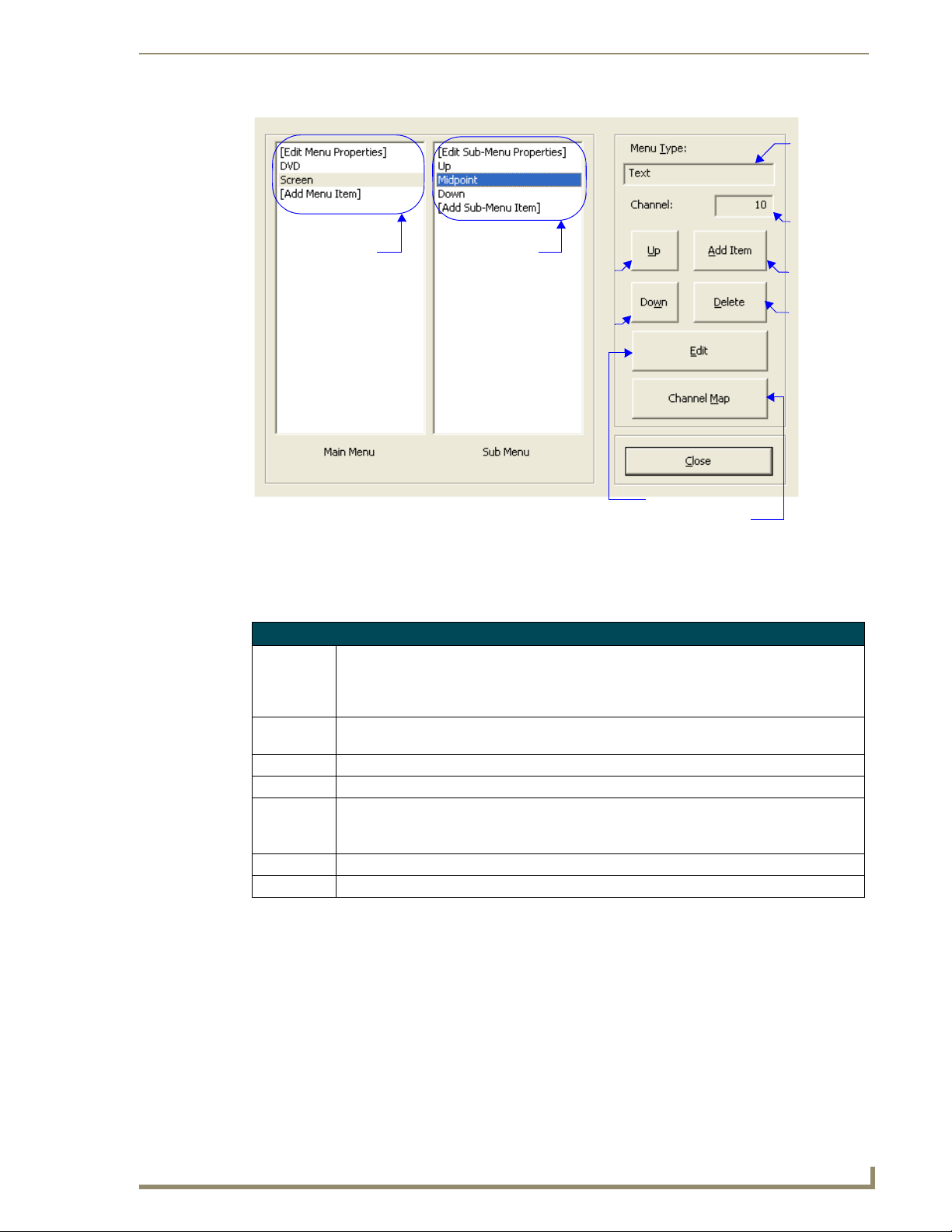
Main menu items
FIG. 25 Fixed Menu Edit Dialog Window
Sub menu items
for selected
main menu item
Move
menu
item up
Move
menu
item
down
Mio Attaché Configuration Modules
Menu type;
either text
or Unicode
Channel
assignment
for selected
menu or
sub menu
Add item to
selected menu
Delete the
selected menu
item
Edit selected menu proper ties
Launch Channel Map
Edit Keypad Menu window
The Edit Keypad Menu window is the same arrangement for both Menu and Sub Menu items.
Edit Keypad Menu Window
Menu Type Click the radio button for either Text, Unicode, or Complex Script. This is the method by which
Button The number for the button currently selected in the Menu Channel Map graphic. Beneath the
Channel Channel assignment for selected menu or sub menu item
Auto Assign Takes the next unassigned channel code.
Channel Map Click Channel Map to view a listing of channel codes that have already been assigned within
OK Confirms changes and closes the window.
Cancel Clears changes and closes the window.
KeypadBuilder displays your menu items within the LCD.
Note: A menu type can only be switched if there are no menu items present, and this is true for
sub menus too.
button number is a list of active button number and their names.
your active KeypadBuilder file.
Click on any channel code number to see its current allocation.
KeypadBuilder v2.1
63
Page 76
Mio Attaché Configuration Modules
Menu Type display items are either Text, Unicode or Complex Script
Button number; button is selected either through the graphic or list.
Button channel assignment. This button cannot be changed because the channel was locked.
FIG. 26 Edit Keypad Menu Dialog Window
64
KeypadBuilder v2.1
Page 77
Mio Attaché Configuration Modules
Add and Edit Menu Item window
The following options apply to keypad menu items that have been designated as the menu type, Te xt .
Add and Edit Menu Item (Text)
Item Caption The name displayed for either the menu or sub menu item.
Has Sub-Menu (only active in
main menu items)
Separator A blank line between items. This line counts as one of the device’s allocated
Select Active (only active in
main menu items)
Return to Main After menu or sub menu item is selected, the display returns to the device’s
Channel Code The assigned channel of either the menu or sub menu selected. Either type a
Auto Assign Takes the next unassigned channel code.
Channel Map Click Channel Map to view a listing of channel codes that have already been
OK Confirms changes and closes the window.
Cancel Clears changes and closes the window.
Assigns a sub menu to the selected menu item.
display lines.
Navigating and releasing on a menu item is the only necessary action to make
it active; there is no need for a select button.
main menu.
channel code in, click the up and down arrows or click Auto Assign to enter a
channel code.
assigned within your active KeypadBuilder file.
Click on any channel code number to see its current allocation.
FIG. 27
Menu item display name
Menu item attributes
Menu item channel code assignment
Add and Edit Menu Item (Text)
KeypadBuilder v2.1
65
Page 78
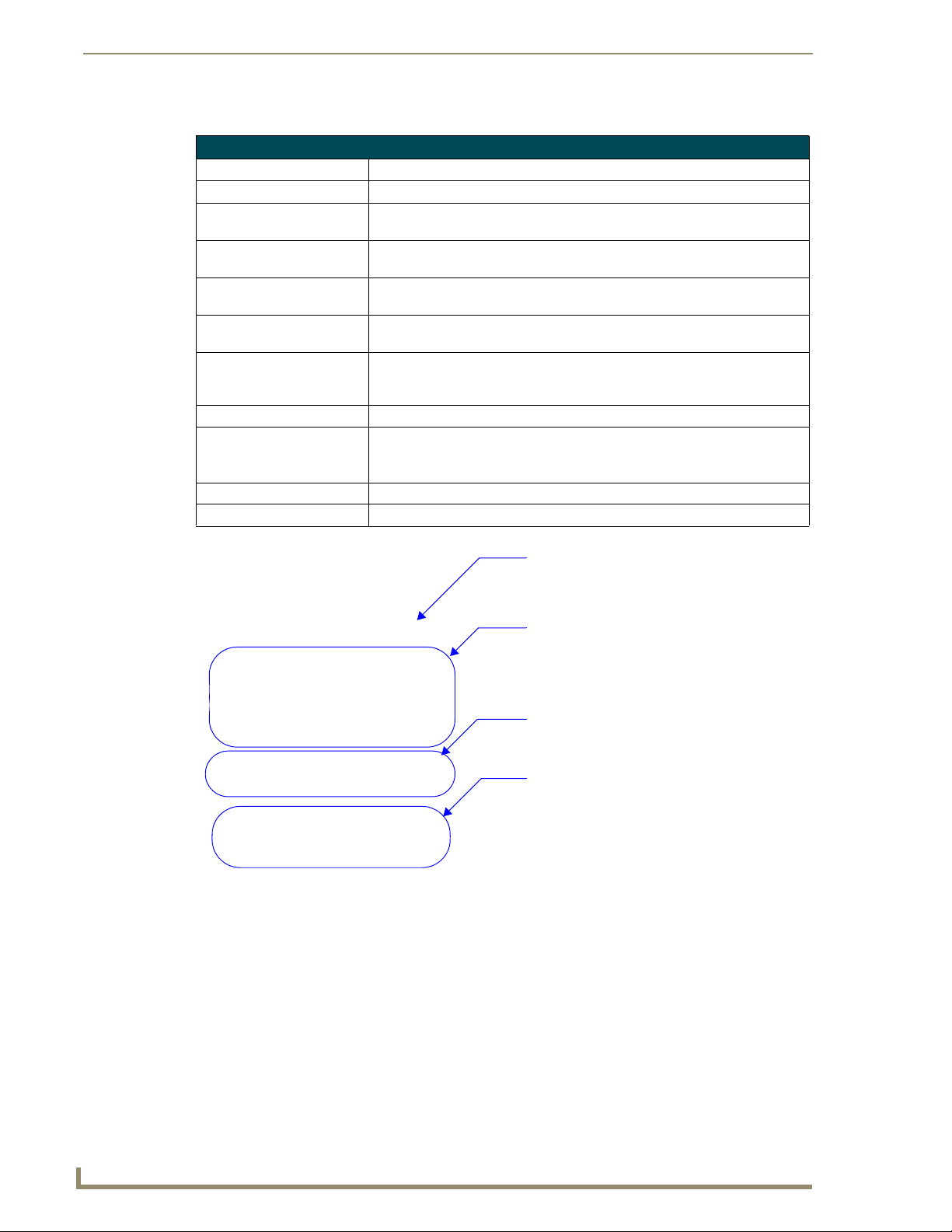
Mio Attaché Configuration Modules
The following options apply to keypad menu items that have been designated as the menu type, Unicode.
Add and Edit Menu Item (Unicode)
Menu Caption The name displayed for either the menu or sub-menu.
Unicode Character Codes The Unicode translation for the text assigned to the menu or sub menu.
Has Sub-Menu (only active in
main menu items)
Separator A blank line between items. This line counts as one of the device’s allocated
Select Active (only active in
main menu items)
Return to Main After menu or sub menu item is selected, the display returns to the device’s
Channel Code The assigned channel of either the menu or sub menu selected. Either type a
Auto Assign Takes the next unassigned channel code.
Channel Map Click Channel Map to view a listing of channel codes that have already been
OK Confirms changes and closes the window.
Cancel Clears changes and closes the window.
Assigns a sub menu to the selected menu item.
display lines.
Navigating and releasing on a menu item is the only necessary action to make
it active; there is no need for a select button.
main menu.
channel code in, click the up and down arrows or click Auto Assign to enter a
channel code.
assigned within your active KeypadBuilder file.
Click on any channel code number to see its current allocation.
FIG. 28
Add and Edit Menu Item (Unicode)
Menu item display name in Unicode
Unicode points associated to menu display
name; characters are separated by pipes
Menu item attributes
Menu item channel code assignment
66
KeypadBuilder v2.1
Page 79
Mio Attaché Configuration Modules
The following options apply to keypad menu items that have been designated as the menu type, Complex
Script.
Add and Edit Menu Item (Complex Script)
Glyph Name The name associated with the glyph. This is for tracking purposes only and is
not displayed within the LCD.
Glyph A sample of the graphic as it appears within the LCD.
Glyph ID Number An ID number KeypadBuilder associates with all glyphs within the project to
Item Name The name of the menu or sub menu item. This value only appears in the
Has Sub-Menu (only active in
main menu items)
Separator A blank line between items. This line counts as one of the device’s allocated
Select Active (only active in
main menu items)
Return to Main After menu or sub menu item is selected, the display returns to the device’s
Channel Code The assigned channel of either the menu or sub menu selected. Either type a
Auto Assign Takes the next unassigned channel code.
Channel Map Click Channel Map to view a listing of channel codes that have already been
Glyph Select List of available glyphs and their current state. Click on a glyph to select.
OK Confirms changes and closes the window.
Cancel Clears changes and closes the window.
ensure unique values.
Fixed-Menu Configuration window.
Assigns a sub menu to the selected menu item.
display lines.
Navigating and releasing on a menu item is the only necessary action to make
it active; there is no need for a select button.
main menu.
channel code in, click the up and down arrows or click Auto Assign to enter a
channel code.
assigned within your active KeypadBuilder file.
Click on any channel code number to see its current allocation.
KeypadBuilder v2.1
67
Page 80

Mio Attaché Configuration Modules
Glyph name
Glyph
Menu item channel code assignment
FIG. 29 Add and Edit Menu Item (Complex Script)
Glyph Select
Glyph ID number
Item Name
Menu item attributes
Complex-Script Glyphs
The Complex-Script Glyph configuration module allows you to create menu/sub-menu items using
characters and fonts that could not otherwise be displayed. Selecting the Complex-script glyph launches
the Add/Edit Keypad Glyphs dialog window.
What is a Complex-Script Glyph?
A complex-script glyph is a rendering of a group of characters without an application dependency for
font or language support. KeypadBuilder creates a graphic image from predefined text and then load the
graphic to your device. This is useful for rendering conditional script languages, displaying proprietary
fonts on devices and utilizing icon type. The only type limitations are what your computer already has;
you cannot display a language you do not have loaded on your PC. Only the glyph and not the font is
ever loaded on your device.
KeypadBuilder supports the creation of 256 glyphs per device project.
68
KeypadBuilder v2.1
Page 81

Mio Attaché Configuration Modules
Add/Edit Keypad Glyphs dialog window
The Add/Edit Keypad Glyphs dialog window allows you to create, edit and manage your menu glyphs.
Add and Edit Keypad Glyphs
Glyph name The name associated with the glyph, this is useful for tracking icon glyphs and multiple
language menu items.
Glyph graphic A thumbnail rendering of the glyph as it displays in the menu.
Glyph selection A list of available glyphs. Click on a glyph to select.
Create new glyph Launches the Create/Modify Glyphs dialog window to create new glyph entries.
Edit existing glyph Launches the Create/Modify Glyphs dialog window to edit existing glyph entries. You must
have a glyph selected in order to edit it.
Delete glyph Toggles a selected glyph from Deleted to not. If you delete a glyph and close the project,
the glyph is gone permanently.
Close Closes the Add/Edit Keypad Glyphs dialog window and enacts changes.
Glyph name
Glyph graphic
Glyph selection
Create new glyph
FIG. 30
Edit existing glyph
Delete glyph
Add and Edit Keypad Glyphs
KeypadBuilder v2.1
69
Page 82
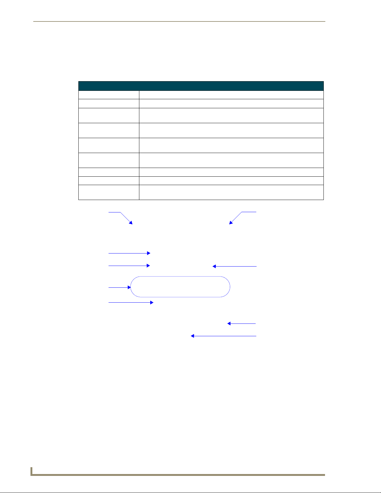
Mio Attaché Configuration Modules
Create/Modify Glyphs dialog window
KeypadBuilder supports the creation of glyph characters. The Create/Modify Glyphs dialog window
allows you to generate graphic representatives for unique script languages and also enables the use of
specialty fonts.
Create/Modify Glyphs
Font type information This is a listing of the family and point size of the font you currently have selected.
Character entry field Click in this field to place the cursor, this is where you type your glyph.
Glyph attributes This is the number of characters your glyph occupies and the dimensions in pixels
Format font selection Launches the Windows font format dialog window. Select the family, format and
Clear character entry field Clears all typed information in the character entry field, only the font information
Create Glyph Renders a glyph from the information typed in the character entry field based upon
Rendered glyph The glyph after Create Glyph is selected. This is what will appear as a menu item.
Glyph Name The name associated with the glyph image.
Glyph ID An automatically assigned value (0-255) for index and application tracking pur-
(WxH). The glyph can be no larger than 96x24.
size of the font.
remains.
the font type and character set selection.
poses.
Font type
information
Character entry
field
Clear character
entry field
Glyph attributes
Rendered glyph
FIG. 31
Create/Modify Glyphs
Format font selection
Create Glyph
Glyph Name
Glyph ID
70
KeypadBuilder v2.1
Page 83

Mio Attaché Application Operations
Mio Attaché Application Operations
Creating A New Project
To create a new KeypadBuilder file, go to File > New Project. The device type that opens depends upon
what is set in the Preferences menu.
Setting The Project Configuration
With a new KeypadBuilder project file open, click Project Properties in the Navigation Pane.
1. Under the Project Information section set the applicable fields:
Project Name - This is user defined. Type the name of your project in this field.
Designer - Type the name of the keypad project designer in this field.
Dealer - Type the name of the Dealer providing the keypad project file.
Project Order - If the keypad project has a project order number, type it in this field.
Sales Order - If the keypad project has a sales order number, type it in this field.
Comments - Any additional comments concerning the project file can be entered in this box.
2. Under the Device Selection section, establish the device that uses the keypad project file. If the
keypad device differs from the default file that opened, select the keypad device from the drop down
menu.
3. Select the color of your keypad device from the drop down list, Color Selection.
4. Click OK to confirm the changes or Cancel to exit and drop all changes.
KeypadBuilder v2.1
71
Page 84

Mio Attaché Application Operations
Setting The Button Configuration
With a new KeypadBuilder project file open, click Button Configuration in the Navigation Pane.
1. By clicking on a button in the Keypad Device area, select a button you wish to configure.
Under Button Properties:
The Number field cannot be edited, it is set by the firmware for the keypad device
selected.
Type the name of the button in the Name field. The button name is useful in tracking channel
2.
assignments. This name should not be confused with what is sent to engraving, this name is strictly
within KeypadBuilder.
3. Enter the Channel Code for the button assignment in the field provided. KeypadBuilder inserts the
next available code if you click Auto Assign.
Placing a check next to Lock Channel for Menus and Sub Menus makes the assigned
channel code unavailable for any other button assignments.
4.
Set the Menu Action value by selecting one from the drop down list. A menu action interacts with
the fixed menu items you can set later.
Up - moves the navigation up through the menu system.
Down - moves the navigation down through the menu system.
Select - activates the navigation item in the menu system.
Home - returns the navigation back to the main menu system.
If you have a menu system, it is a good idea to be aware of possible navigation
issues. When you have more menu line items than what is supported by your device
display, an Up and Down menu action allows you to access them. If you have submenus, you might need a Home menu action to return you to the main menu.
5. Click Update to set the values for your selected button. Clicking on another button before clicking
Update will drop all settings for your selected button. Repeat this for all of your buttons including
the LCD button.
6. Set the Configuration Options
To create blank buttons, click Blank Buttons. Now click on any button in the Keypad Device
area to make it a blank. Making a button that previously held information blank drops all
configuration information. Click Blank Buttons again to exit mode.
To combine buttons, click Combine Buttons. Click on any button and it combines with the
button to its immediate right. The button configuration information of the right button is
dropped. Click Combine Buttons again to exit mode.
It is important to set your blank and combined buttons before creating the engraving
file; they are included in the custom order you place with AMX.
7. Click OK to confirm the changes or Cancel to exit and drop all changes.
72
KeypadBuilder v2.1
Page 85

Mio Attaché Application Operations
Creating The Engraving File
With a new KeypadBuilder project file open, click Engraving in the Navigation Pane.
1. By clicking on a button in the Keypad Device area, select a button you wish to engrave.
The Number field cannot be edited, it is set by the firmware for the keypad device
selected.
If you have already set the Button Configuration module, the Name and Menu Action
fields are populated.
2.
In the Font Selection drop down menu, select between placing a symbol, AMX Icon 2, or text, Arial
Unicode MS. There is a maximum of 10 characters per button.
If you selected Arial Unicode MS, type the text you want displayed in the Te xt field.
If you selected AMX Icon 2, the Symbol drop down menu is enabled. Either select the symbol
from the list or type the corresponding keyboard character in the Tex t field. Buttons can have
more than one character.
The KeypadBuilder Engraving module supports the engraving of its listed supported
OS languages. You must have the language loaded on you OS and then use Unicode
to render the text on the button.
3. Set the size of either the symbol or text on the button. Click on the Scale drop down menu and select
in a range from 0.5 to 1.5.
4. Click Update.
5. To preview the .DXF file as it appears to the engraver, click Preview...
6. Click Export DXF File... to create the DXF file.
7. Within the Export DXF File dialog window, set the destination directory for the file. Either type or
click Browse to determine where to save the file.
8. Type a Description of the file in the field provided. The description aids in making a unique file
name for the engraver.
The File to Export field displays what the final file name is. For example:
C:\(Media Room)-S12-D0-SB0-DB0-CElite Taupe.DXF
KeypadBuilder v2.1
Anatomy of A DFX File
C:\ Destination directory for the .DXF file.
(Media Room) Populated by the Description field.
S12 12 single buttons.
D0 0 double buttons.
SB0 0 single blank buttons.
DB0 0 double blank buttons.
CElite An Elite keypad device.
Taupe The keypad color is taupe.
9.
Click Export to confirm and create the DXF file.
10. Click Done to exit the dialog window.
11. Click OK to save changes to the Engraving module and return to the Navigation Pane.
73
Page 86

Mio Attaché Application Operations
Setting The LCD Configuration
With a new KeypadBuilder project file open, click LCD Configuration in the Navigation Pane. After
you have set the options you need, click OK.
Display Options
Under LCD Display Resolutions, select the arrangement for your LCD device.
Click on the font family and the number of lines to display on the device menu.
Dynamic Text
If you want to designate any lines as dynamic you must make a selection under Dynamic Text.
Click on the number of lines you want set as dynamic.
Based on the number of lines you select as being dynamic, the rest are allocated to menu items. It is
possible to have either all or no dynamic lines.
If you established dynamic items, select to display the dynamic items at the Top or Bottom under Align.
The display lines cannot alternate between menu and dynamic items.
Click the radio button next to either Top or Bottom.
Line Options
Based on your selection in the Dynamic Text section, the Line Options section could be populated with
all menu items, all dynamic items or a mix of the two.
1. Click on the line number you want to edit.
2. You can change the justification of menu items. Click the radio button to move the item either Left,
Center, or Right.
In addition to justification you can set other values for dynamic items:
Remove the check next to Visible to remove the dynamic item from the display.
Place a check next to Level to make the dynamic display line a level indicator.
If you set the dynamic line as a level, click the Level Style you want to display.
Sleep Screen Display Options
You can set the LCD to display an image when not in use or "sleep" mode. The image must be
monochrome and cannot exceed 96 x 96 pixels.
1. Click the Import Icon... button to launch the Import Splash Screen Icon File dialog window.
2. Locate your file and click Open. Below the image reads, "Splash Screen Active."
74
KeypadBuilder v2.1
Page 87

Mio Attaché Application Operations
Setting The Fixed-Menu Configuration
With a new KeypadBuilder project file open, click Fixed-Menu Configuration in the Navigation Pane.
Click Close when you have set all options necessary.
Edit Menu Properties
By default KeypadBuilder is set to create the display items in text. If you plan to use Unicode you must
set it before adding any menu items, the same applies when adding sub menus.
1. In the Fixed Menu Edit dialog window, select Edit Menu Properties in the Main Menu field.
2. Click Edit to launch the Edit Keypad Menu dialog window.
3. Click either the Tex t or Unicode radio button under the Menu Type section. This setting applies to all
menu items.
Under Menu Channel Map notice the Button field is a list of the button numbers with the names you
assigned in the Button Configuration module. The box directly to the right of Button displays the
currently selected button number. You can select buttons by either clicking on them in the Button list or
selecting the button on the graphic keypad device.
If not already set, you can assign channels at this time. You can either:
Type the channel number in the field next to Channel.
Click the UP and DOWN arrows next to the Channel field to navigate through the numbers.
Click Auto As sign and KeypadBuilder will allocate the next available channel.
If you are uncertain as to what channels have been assigned where, click Channel Map to see.
4. Click Update after you make changes to each button.
5. Click OK after you are done.
Add a Menu Item (Text)
In the Fixed Menu Edit dialog window, select Add Menu Item in the Main Menu field.
1.
2. Click Add Item to launch the Add/Edit Menu Item dialog window.
3. Type the name of the menu item as it is to display in the LCD in the field Item Caption.
4. Place a check in the boxes of all items that apply:
Has Sub-Menu - Creates an entry beneath this display item.
Separator - This display item has no value and therefore cannot have any other box selections.
This does count as one of your display lines.
Select Active - Item executes upon selection; does not require a select menu action.
Return to Main - The menu returns to the top level after this item has been selected.
5. If this menu item requires a channel assignment either type it or click Auto Assign to have
KeypadBuilder allocate the next available channel.
If you are uncertain as to what channels have been assigned where, click Channel Map to see.
6. Click OK when you are done.
Add a Menu Item (Unicode)
In the Fixed Menu Edit dialog window, select Add Menu Item in the Main Menu field.
1.
2. Click Add Item to launch the Add/Edit Menu Item dialog window.
3. Enter the Unicode text in the Menu Caption field. The corresponding Unicode Send Command
Va l ue is displayed beneath the text box.
4. Click OK to return to the Add/Edit Menu Item dialog window.
5. Place a check in the boxes of all items that apply:
Has Sub-Menu - Creates an entry beneath this display item.
KeypadBuilder v2.1
75
Page 88

Mio Attaché Application Operations
Separator - This display item has no value and therefore cannot have any other box selections.
This does count as one of your display lines.
Select Active - Item executes upon selection; does not require a select menu action.
Return to Main - The menu returns to the top level after this item has been selected.
6. If this menu item requires a channel assignment either type it or click Auto Assign to have
KeypadBuilder allocate the next available channel.
If you are uncertain as to what channels have been assigned where, click Channel Map to see.
7. Click OK when you are done.
Edit Sub-Menu Properties
By default KeypadBuilder is set to create the display items in text. If you plan to use Unicode you must
set it before adding any sub-menu items. You can only edit and add sub-menu properties when they have
been assigned to menu items.
1. In the Fixed Menu Edit dialog window, select a main menu item that has a sub-menu.
2. Edit Sub-Menu Properties in the Sub Menu field.
3. Click Edit to launch the Edit Keypad Menu dialog window.
4. Click either the Tex t or Unicode radio button under the Menu Type section. This setting applies to all
sub-menu items.
Under Menu Channel Map notice the Button field is a list of the button numbers with the names you
assigned in the Button Configuration module. The box directly to the right of Button displays the
currently selected button number. You can select buttons by either clicking on them in the Button list or
selecting the button on the graphic keypad device.
If the buttons are not locked to a particular channel, you can assign channels at this time. These channel
assignments only apply when you have selected the menu item. You can either:
Type the channel number in the field next to Channel.
Click the UP and DOWN arrows next to the Channel field to navigate through the numbers.
Click Auto As sign and KeypadBuilder will allocate the next available channel.
If you are uncertain as to what channels have been assigned where, click Channel Map to see.
5. Click Update after you make changes to each button.
6. Click OK after you are done.
76
Add a Sub-Menu Item (Text)
In the Fixed Menu Edit dialog window, select Add Sub-Menu Item in the Sub Menu field.
1.
2. Click Add Item to launch the Add/Edit Menu Item dialog window.
3. Type the name of the menu item as it is to display in the LCD in the field Item Caption.
4. Place a check in the boxes of all items that apply:
Separator - This display item has no value and therefore cannot have any other box selections.
This does count as one of your display lines.
Return to Main - The menu returns to the top level after this item has been selected.
5. If this sub-menu item requires a channel assignment either type it or click Auto Assign to have
KeypadBuilder allocate the next available channel.
If you are uncertain as to what channels have been assigned where, click Channel Map to see.
6. Click OK when you are done.
KeypadBuilder v2.1
Page 89

Mio Attaché Application Operations
Add a Sub-Menu Item (Unicode)
In the Fixed Menu Edit dialog window, select Add Sub-Menu Item in the Sub Menu field.
1.
2. Click Add Item to launch the Add/Edit Menu Item dialog window.
3. Enter the Unicode text in the Menu Caption field. The corresponding Unicode Send Command
Va l ue is displayed beneath the text box.
4. Click OK to return to the Add/Edit Menu Item dialog window.
5. Place a check in the boxes of all items that apply:
Separator - This display item has no value and therefore cannot have any other box selections.
This does count as one of your display lines.
Return to Main - The menu returns to the top level after this item has been selected.
6. If this sub menu item requires a channel assignment either type it or click Auto Assign to have
KeypadBuilder allocate the next available channel.
If you are uncertain as to what channels have been assigned where, click Channel Map to see.
7. Click OK when you are done.
Arranging Menu and Sub Menu items
In both the Main and Sub Menu fields, the items are appear top to bottom as they do in the LCD.
To move an item:
1. Select the menu item from the list.
2. Click either Up or Down to move the item within the list.
To remove an item:
1. Select the menu item from the list.
2. Click Delete.
To undo the delete:
Select the deleted item from the list and click Delete again. If you click Close, save and exit,
you will not be able to undelete.
KeypadBuilder v2.1
Creating Complex-Script Glyphs
To create a glyph for use as a menu or sub -menu item:
1. With a KeypadBuilder project open, click Complex-Script Glyphs from the navigation pane.
2. Click New Glyph in the Add/Edit Keypad Glyphs dialog window.
3. Click the format font selection button (...) to launch the Windows font format dialog window. Select
the family, format and size of the font and click OK.
4. In the Character Select drop down list, select the language character set you wish to use. Your
operating system must support this or you must use a keyboard language interface.
5. Place your cursor in the Text field and type what you wish to make a glyph. it can be no larger than
96x24 pixels. If you make a mistake click Clear to start fresh.
6. Click Create Glyph to render your glyph. The glyph will not create if you exceeded the text
dimensions.
7. In the field Glyph Name, type in name that will help you associate that glyph within your project.
8. Click OK to accept the glyph.
77
Page 90

Mio Attaché Application Operations
Editing Glyphs
To edit a glyph for use as a menu or sub -menu item:
1. With a KeypadBuilder project open, click Complex-Script Glyphs from the navigation pane.
2. Select from the list the glyph you intend to edit.
3. Click Edit Glyph in the Add/Edit Keypad Glyphs dialog window.
Select from the following steps to edit your glyph:
Change the font format or family - Click the format font selection button (...) to launch the
Windows font format dialog window. Select the family, format and size of the font and click
OK.
Change the language character set - In the Character Select drop down list, select the
language character set you wish to use. Your operating system must support this or you must
use a keyboard language interface.
Change the characters in the glyph - Place your cursor in the Text field and type what you
wish to make a glyph. it can be no larger than 96x24 pixels. If you make a mistake click Clear
to start fresh.
1. Click Create Glyph to render your glyph. The glyph will not create if you exceeded the text
dimensions.
2. If necessary, in the field Glyph Name, type in name that will help you associate that glyph within
your project.
3. Click OK to accept the glyph.
Deleting Glyphs
To delete a glyph no longer in use as a menu or sub -menu item:
1. With a KeypadBuilder project open, click Complex-Script Glyphs from the navigation pane.
2. Select from the list the glyph you intend to delete.
3. Click Delete Glyph in the Add/Edit Keypad Glyphs dialog window.
4. Click OK to accept the deletion of the glyph.
78
KeypadBuilder v2.1
Page 91

Program Reference
Basic Usage Dialogs
Open KeypadBuilder Project dialog window
The Open KeypadBuilder Project dialog window is a typical windows dialog window that allows you to
browse your system and open a targeted .KPB file.
Select a file and click OK to confirm and open the file in KeypadBuilder. Click Cancel to close the
window without opening a file.
Save As dialog window
The Save As dialog window is available either when it is the file’s first instance of save or when you want
to save under a separate version in order to keep the previous file intact.
Browse to the file destination and type the File name in the field provided.
Click OK to confirm and save the file or click Cancel to close the window without saving the file.
Channel Map dialog window
The Channel Map is a listing of channel codes that have already been assigned within your active
KeypadBuilder file.
Click on any channel code number to see its current allocation.
Program Reference
KeypadBuilder v2.1
79
Page 92
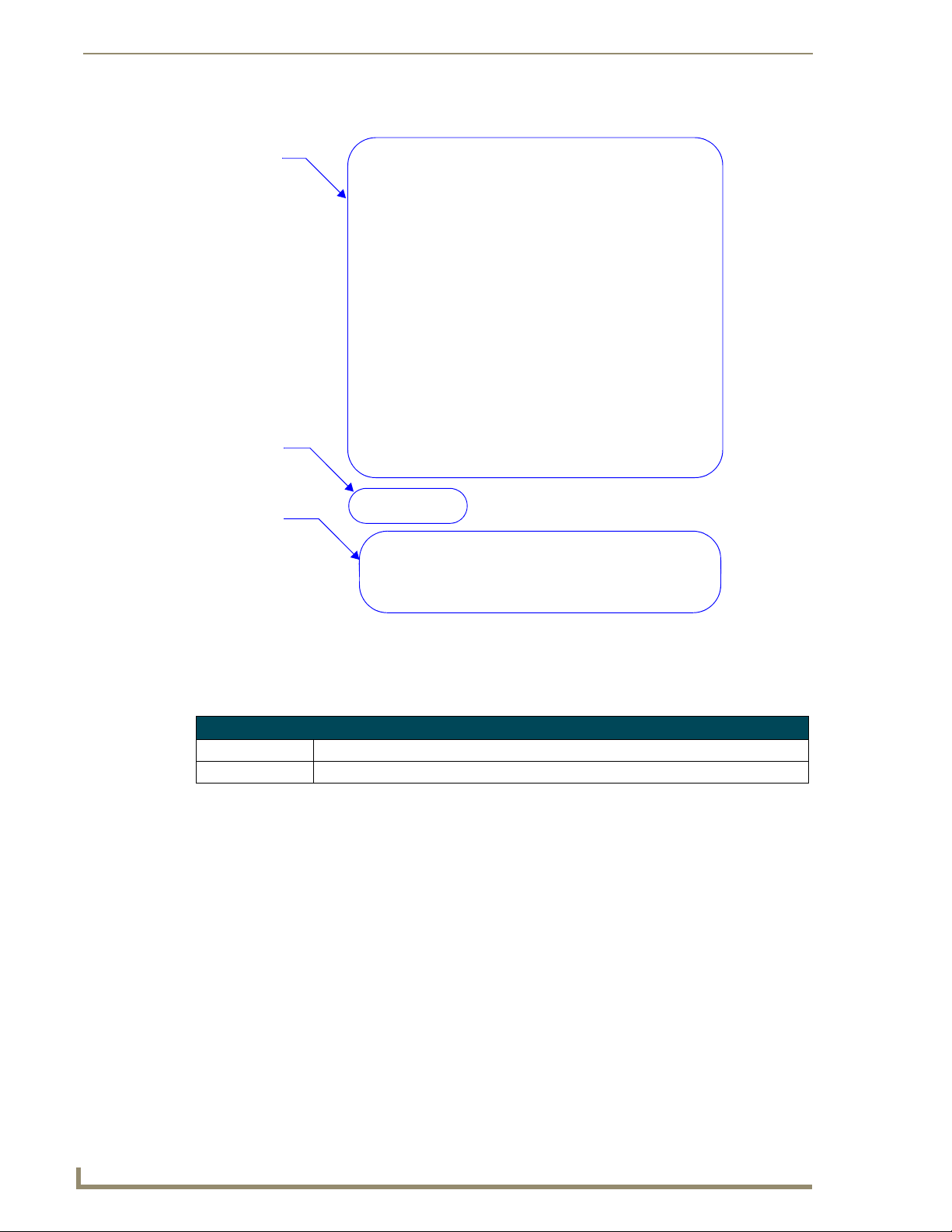
Program Reference
Channel numbers
Currently selected
channel number
Channel
assignment
information;
button and
description
FIG. 32 Channel Map Dialog Window
Channel Information
Channel Code The assigned channel code number.
Assigned To If used, the item and description of the button using the channel code.
80
KeypadBuilder v2.1
Page 93
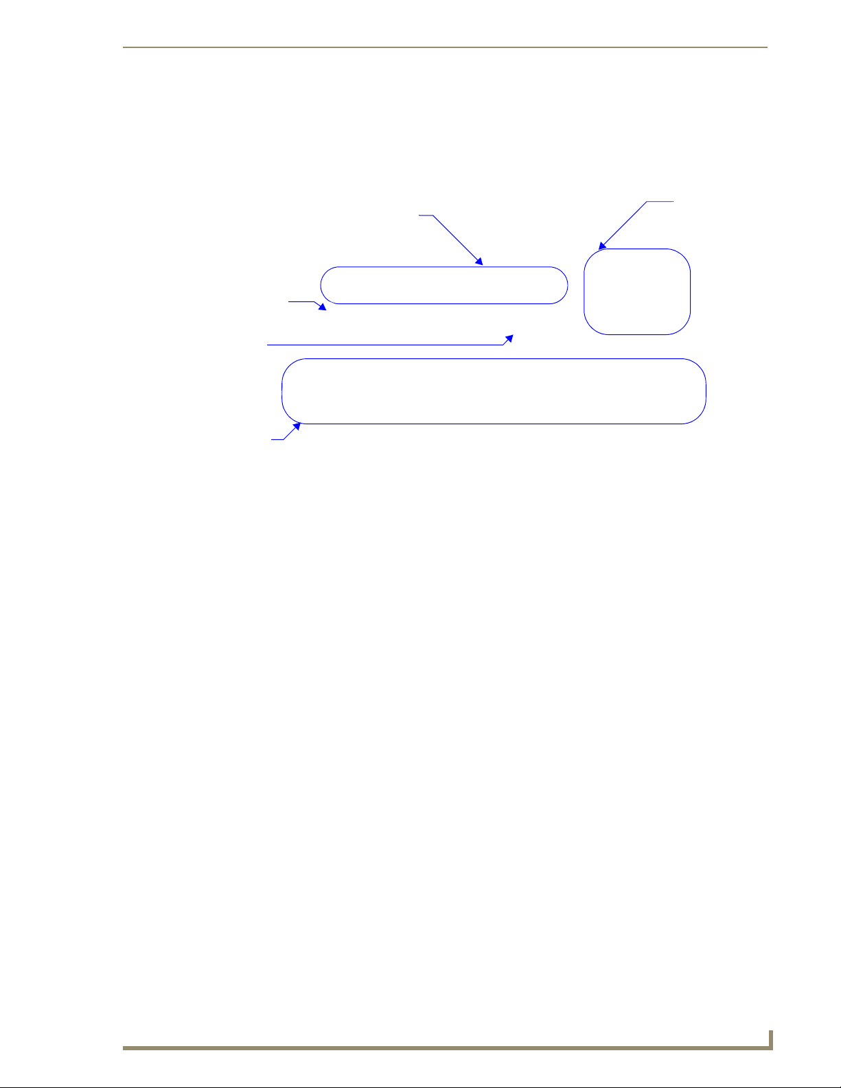
Program Reference
File Transfer Dialogs
Send Configuration Files dialog window
The Send Configuration Files dialog window allows you to see the current settings for sending files,
change and set the connection method and send the file.
The files to be sent to
the master.
Click to
set the
communications
settings
Device ID
number
The status
of the file
transfer
Current communication settings
FIG. 33 Send Configuration Files Dialog Window
Communication Settings - The display field shows you the current communication setting
for KeypadBuilder.
The Communication Settings... button launches the Communication Settings dialog
window.
Device ID - Type the Device ID number for the currently targeted device.
Send File Options - Click the box to include the information sent to the device.
Configuration File - This is the file that sets the button functionality, channel
assignments, and menu behaviors
Font File - If the font used in menu display is not already loaded on the device, it is
necessary to include this file in the send.
Glyph File - If you selected Complex Script menu items and created glyphs, you
need to check this box to include them in the download file.
Send File - Click this button after the communications have been set to send the selected files
to the targeted device.
Done - Click this button after you have received indication of a successful send in the Transfer
Status field. Done closes the dialog window.
KeypadBuilder v2.1
81
Page 94

Program Reference
Communication Settings dialog window
Use the options in this dialog to configure and save new communications settings, or to edit a saved
communications configuration. The options in this dialog include:
Platform Selection - Select the platform type by clicking the appropriate radio button
(NetLinx Master, Axcess Master)
Transport Connection Option - Select a transport type by clicking the appropriate radio
button (Modem, Serial or TCP/IP).
TCP/IP is only available for NetLinx masters.
Edit Settings - launches the Edit Settings dialog window.
Authentication Required - Click the Authentication Required checkbox to enable the User
name and Password button
Edit Settings dialog window
Edit Settings - This window contains communication parameters specific to the selected transport type.
If you selected Modem, the parameters are COM Port, Data Bits, Parity, Baud Rate, Stop Bits,
Flow control and Phone Number.
If you selected Serial, the parameters are COM Port, Data Bits, Parity, Baud Rate, Stop Bits
and Flow control.
If you selected TCP/IP, the parameters are IP Address/DNS Name and IP Port. The IP Port
should always be set to 1319 (default). Do not change this number. TCP/IP connections also
feature the option to ping the NetLinx Master to ensure availability (default = enabled; disable
if Master is behind a firewall that blocks ICMIP ping messages).
User Name and Password dialog window (for NetLinx Master)
Authentication Required - If the target NetLinx Master has authentication enabled, you are prompted
to enter a User Name and Password in order to establish a connection. Click the Authentication Required
checkbox to enable the User name and Password button; click the button. Enter the User Name/
Password combination to save them as part of this configuration. Once they are entered here, you will be
able to establish this connection without having to type the authentication information each time you
connect. Refer to the NetLinx Studio (v2.3 or higher) online help for details on enabling authentication
on NetLinx Masters.
82
KeypadBuilder v2.1
Page 95
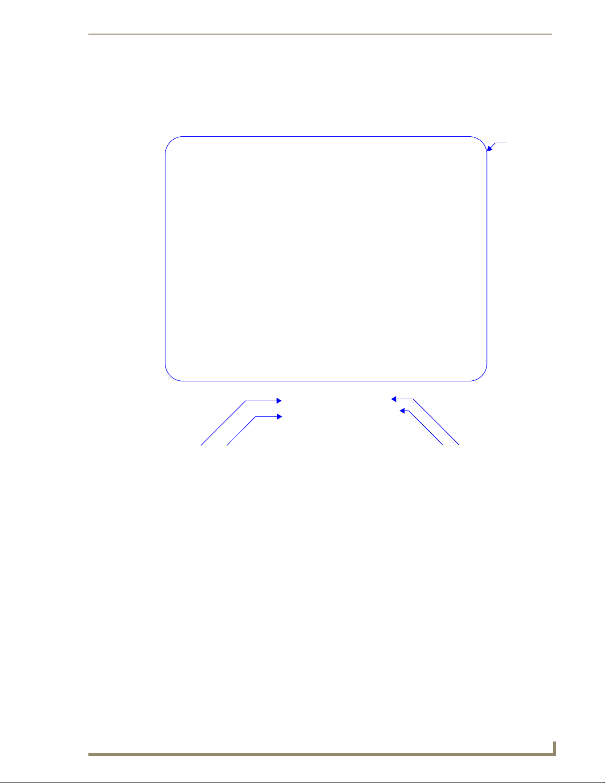
Program Reference
Generate Project Report Dialog
The Project Report dialog window is a detailed list of your KeypadBuilder file. The report is in ASCII
text and as a result, sections can be copied or the whole report can be saved as a .TXT file.
Project
report
Copy selected
lines
FIG. 34 Generate Project Report Dialog
Save project file
Copy selected
lines
Copy entire report
The main display area is the Project Report. The sections within the report are Project Properties, Button
Configuration Information, LCD Configuration Information, Fixed Menu System Configuration
Information, and Channel Map Information.
In the Options section, you can click Copy to Clipboard or Save to File... The Copy to Clipboard
option has two settings, Full Report; which, will copy the entire report to the clipboard, or Selected
Lines; which, will copy only the lines you have highlighted.
To close the window click Done when you have finished with the Project Report.
KeypadBuilder v2.1
83
Page 96

Program Reference
Application Setup Dialog
Preferences dialog window
The Preferences dialog window allows you to customize the KeypadBuilder application.
The default
keypad device
Available
button
information
The default
device color
The default
device type
The number
of most recently
viewed files to
display
FIG. 35 Preferences Dialog Window
Default Device for New Projects - Select a device from the drop-down list. All new projects
will start with this device type by default. This is useful if you are primarily programming on
device type. Your selection is dictated by the type of device radio button field.
Type of Device - Click the radio button for the device type, Keypad or Remote, you primarily
use.
Color Selection - Select a color from the drop-down list. All new projects will start with this
device type by default. The available colors are dictated by the device selected.
Show Button Names - When checked, the button names are displayed in the Navigation
Pane.
Show Button Numbers - When checked, the button numbers are displayed in the Navigation
Pane.
Show Channel Codes - When checked, the button channel codes are displayed in the
Navigation Pane.
Show Menu Actions - When checked, the button menu actions are displayed in the
Navigation Pane.
Show Engraving Text - When checked, the button engraving information is displayed in the
Navigation Pane.
84
KeypadBuilder v2.1
Page 97

Program Reference
Engraving Dialogs
Export DXF File dialog window
The Export DXF dialog window allows you to set the destination directory for the file, make the file
unique and confirm the DXF file name.
Directory Location - Either type the target directory to create the DXF file or click Browse to
navigate to the directory.
Description - Type a description of the file the engraving applies to, this information helps
make the DXF unique.
File to Export - This field is the final name for the DXF.
Export - Creates the DXF in the target directory.
Done - Finishes the DXF creation session and closes the window.
Engraving Template Preview dialog window
The preview is what the exported DXF looks like. This is a preview of the jig sent to the engraver.
Zoom In - Move the view range in on the preview area.
Zoom Out - Move the view range out away from the preview area.
Normal - Returns the view area to the default.
Click on the preview area and hold to drag the image. You can also use your mouse wheel to zoom in and
out of the preview area.
Click Done to close the Preview dialog window.
Notice the difference between a proper and improper engraving selection. Within the preview image is a
button and bounding box. The bounding box represents the outermost area of the button that can be
engraved. If the character touches or exceeds the bounding box, the DXF file will not be created and
KeypadBuilder notifies you of the issue.
LCD Configuration Dialogs
Import Splash Screen Icon File dialog window
Some LCD devices support splash images.
The Import Splash Screen Icon File dialog window allows you to navigate to the appropriate graphic
image.
Select the graphic file and click Open to confirm your selection. Click Cancel to exit the dialog window
without importing a graphic file.
Remove dialog window
If a splash screen image is in place, click Remove. KeypadBuilder asks you to click Ye s to confirm the
removal or click No and leave the file in place.
KeypadBuilder v2.1
85
Page 98

Program Reference
86
KeypadBuilder v2.1
Page 99

The Mio DMS KeypadBuilder Work Area
The Mio DMS KeypadBuilder Work Area
Design View Window
FIG. 36 Design View Window
The design view window is a graphic representation of either your currently selected page or list table.
You can select a page or table in the Workspace Navigator - Pages Tab. You can select pages and list box
tables to edit or in the event it is associated, you can use the page flip.
Click within the scroll/button area or on the menu item to navigate and select within the Design View
window.
KeypadBuilder v2.1
87
Page 100

The Mio DMS KeypadBuilder Work Area
Button Information Window
FIG. 37 Button Information Window
Below the button navigation list of the Page Navigation window is the text box, Button Information
window.
The text area of the Button Information window provides which line is currently selected, if the button
has a page flip attribute assigned, the port address of the button and the channel code for the button.
In the event you have created a keypad page that drills down without any means of navigating back out,
this window will read Page Flip = NeedPageFlip. Allocate one of the buttons to return to another page
with further navigation.
Page Navigation Window
The Page Navigation window provides helpful information and quick navigation for editing button
features on selected pages. All pertinent page information is displayed in the visually appealing black
boxes complemented with the yellow text. The text box at the top of the Page Navigation indicates which
page you currently have selected an in view in the Design View Window. Below the page title is a button
navigation list for selecting and editing buttons on the current page.
The button navigation list contains 8 button regions and 2 "hidden" buttons that serve as navigation for
each keypad page. There are 4 possible button icon types found in the button navigation list. Select any
button and go to Project > Button Item Properties to edit or change any of the following button types.
Right-click on any button to access the List box Button Properties Dialog Window.
General Button : The General buttons are the basic buttons in both the button select
Mio Modero DMS and touch select Mio Modero DMS Pinnacle. General buttons can serve as
page flips, list box navigators and provide feedback. There can only be 8 general buttons per
page.
Page Navigation Button : KeypadBuilder includes a scroll up and down navigation
button with each keypad page. While the buttons are considered "hidden," some programming
properties can be edited. If a list box is present on the page, the Page Navigation buttons can
be assigned to navigate them. Page Navigation buttons can also be assigned page flips. The
Page Navigation buttons and General buttons 1 and 8 occupy the same buttons on Mio
Modero DMS devices. The Page Navigation properties will override the General button
properties in the event they differ.
List box Button : KeypadBuilder makes use of the new format, List box buttons. Both
static and dynamic list boxes allow nearly limitless button options beyond the physical
limitations of device's General buttons. A list box button's display area is limited to the
number of button lines allocated to via the Page Configuration Dialog Window. A List box
button used in conjunction with a List box Navigation button can display several devices or
channels.
List box Navigation Button : A List box button just isn't as cool as it could be without
its partner List box Navigation button. List box Navigation buttons have incremental options
that are assigned in the Button Properties Dialog Window. List box Navigation buttons are
necessary if your list box exceeds the line viewing area, e.g., the list box is 2 lines and you
have 3 devices in your list.
88
KeypadBuilder v2.1
 Loading...