

Page 1
instruction manual
IRIS
Infrared/Serial Data Capture Unit
Control System Accessories
Page 2

AMX Limited Warranty and Disclaimer
AMX Corporation warrants its products to be free of defects in material and workmanship under normal use for
three (3) years from the date of purchase from AMX Corporation, with the following exceptions:
• Electroluminescent and LCD Control Panels are warranted for three (3) years, except for the display and touch
overlay components that are warranted for a period of one (1) year.
• Disk drive mechanisms, pan/tilt heads, power supplies, MX Series products, and KC Series products are
warranted for a period of one (1) year.
• Unless otherwise specified, OEM and custom products are warranted for a period of one (1) year.
• Software is warranted for a period of ninety (90) days.
• Batteries and incandescent lamps are not covered under the warranty.
This warranty extends only to products purchased directly from AMX Corporation or an Authorized AMX Dealer.
AMX Corporation is not liable for any damages caused by its products or for the failure of its products to perform.
This includes any lost profits, lost savings, incidental damages, or consequential damages. AMX Corporation is not
liable for any claim made by a third party or by an AMX Dealer for a third party.
This limitation of liability applies whether damages are sought, or a claim is made, under this warranty or as a tort
claim (including negligence and strict product liability), a contract claim, or any other claim. This limitation of
liability cannot be waived or amended by any person. This limitation of liability will be effective even if AMX
Corporation or an authorized representative of AMX Corporation has been advised of the possibility of any such
damages. This limitation of liability, however, will not apply to claims for personal injury.
Some states do not allow a limitation of how long an implied warranty last. Some states do not allow the limitation or
exclusion of incidental or consequential damages for consumer products. In such states, the limitation or exclusion of
the Limited Warranty may not apply. This Limited Warranty gives the owner specific legal rights. The owner may
also have other rights that vary from state to state. The owner is advised to consult applicable state laws for full
determination of rights.
EXCEPT AS EXPRESSLY SET FORTH IN THIS WARRANTY, AMX CORPORATION MAKES NO
OTHER WARRANTIES, EXPRESSED OR IMPLIED, INCLUDING ANY IMPLIED WARRANTIES OF
MERCHANTABILITY OR FITNESS FOR A PARTICULAR PURPOSE. AMX CORPORATION
EXPRESSLY DISCLAIMS ALL WARRANTIES NOT STATED IN THIS LIMITED WARRANTY. ANY
IMPLIED WARRANTIES THAT MAY BE IMPOSED BY LAW ARE LIMITED TO THE TERMS OF THIS
LIMITED WARRANTY.
Page 3

Table of Contents
Table of Contents
Product Information .................................................................................................1
Specifications .................................................................................................................... 1
Installation .................................................................................................................3
Capturing HC Functions .................................................................................................... 3
Capturing HC functions in default mode .................................................................................. 3
Capturing HC functions in SP mode ........................................................................................ 4
Capturing difficult HC functions using P3-P8 modes ............................................................... 4
Display Characters and P Mode Settings.......................................................................... 4
Baud Rate Settings ........................................................................................................... 5
Cables and Adapters......................................................................................................... 6
HC IR Functions ................................................................................................................ 6
Troubleshooting .......................................................................................................9
E1 or ER messages ................................................................................................................. 9
IRIS Infrared/Serial Data Capture Unit
i
Page 4

Table of Contents
ii
IRIS Infrared/Serial Data Capture Unit
Page 5
Product Information
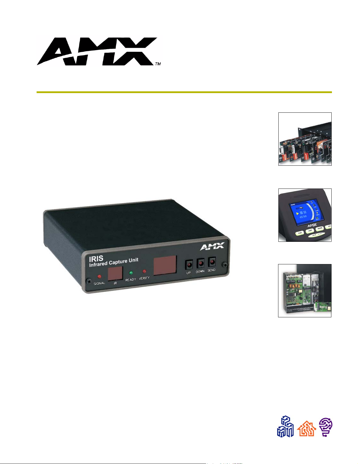
The IRIS Infrared Capture Unit is a stand-alone, self contained unit used to capture infrared (IR) or
wired-IR function signals from a hand controller. Hand controllers (HC) are used to control a wide
variety of audiovisual equipment that includes monitors, VCRs, TVs, and CD players. After you
capture IR functions with the IRIS unit (FIG. 1 on page 2), the functions are sent to a PC running
the IRLIB software program. The IRLIB software program creates HC function files that are
downloaded to the AXCESS Central Controller. For step-by-step instructions on how to use the
IRLIB software program, refer to the IRLIB Infrared Library Management Program instruction
manual.
Specifications
Specifications
Power 12 VDC @ 160 mA max.
Dimensions (HWD) 1.51" x 5.55" x 5.45" (3.84 cm x 14.10 cm x 13.84 cm)
Weight 18.2 oz (518.2 g)
Front Panel Components:
SIGNAL LED Red indicator that blinks when the IRIS unit is receiving HC functions.
IR window captures HC functions.
READY LED Green indicator that lights when the IRIS unit is ready to receive HC functions.
VERIFY Red indicator that lights when the IRIS unit is ready to verify HC functions.
Alphanumeric display (2-digit) Red 7-segment alphanumeric display that shows the capture mode
and operating status.
UP Increments the alphanumeric display by one and lights the red LED inside the
pushbutton.
DOWN Decrements the display by one and lights the red LED inside the pushbutton.
SEND Transmits captured HC functions to a PC running the IRLIB software program.
The red LED inside the pushbutton lights when valid HC functions are ready to
send.
Rear Panel Components:
12 VDC/12 VAC connector 2-pin (male) 12 VDC or 12 VAC power supply connector.
8-pin data connector Captures wired-IR HC functions. Connect the HC to the IRE IN or WIRED IN
pins.
RS-232 connectors • DB-9 connector for data communications with a PC.
• 6-pin RJ-11 modular connector for data communications. The RJ-11
connector is only used with older SX-DCU+ products.
Control ports • IR sensor to receive IR codes; IR serial input for wired IR codes.
• DB-9 female connector for Axcess and PC communication.
Enclosure Metal with black matte finish
Includes • Large, 2-digit status LED
• Adjustable RS-232 port (300 - 9600 baud)
• 12 VAC power supply
• IRLIB software for IBM-compatible computers
Product Information
IRIS Infrared/Serial Data Capture Unit
1
Page 6

Product Information
IR window
SIGNAL LED
12 V connector
8-pin data
connector
SIGNAL
READY LED
VERIFY LED
IRE
12V IN
READY VERIFY
IR
WIRED
IN OUT
Alphanumeric display
UP button
DOWN button
UP
DOWN SEND
SEND button
12
5
RS-232
RS-232
RS-232 6-pin
RJ-11 connector
RS-232 DB-9
connector
FIG. 1 IRIS front and rear views
2
IRIS Infrared/Serial Data Capture Unit
Page 7

Installation
Capturing HC Functions
The two modes you can use to capture HC functions are default and special function. You use
default mode, which is automatically set when you connect power to the IRIS unit, to capture the
majority of HC functions. The table below shows the IRIS unit settings for default mode. Before
capturing HC functions, make sure the baud rate in the IRIS unit is set properly, and connected to a
PC running the IRLIB Library Management Program. Refer to the IRLIB Library Management
Program instruction manual to store captured HC functions.
Default Mode Settings
Default Setting
Baud 9600
P3 off
P4 on
P5 off
P6 on
P7 on
P8 off
Installation
Capturing HC functions in default mode
To capture HC functions in default mode:
1. Make a list of the name and sequence of the HC functions you want to capture. The standard
order for HC functions is listed in the HC IR Functions section on page 6.
2. Connect the RS-232 cable to the DB-9 connector on the IRIS unit and the RS-232 port on your
PC, as shown in the Cables and Adapters section on page 6. Set the baud rate in the IRIS unit
to match the PC baud rate. Refer to the Baud Rate Settings section on page 5 to set the baud
rate. Then, connect the 12
unit. The
READY LED lights and 01 appears in the display.
3. Hold the HC device approximately 3-inches away from the
the first key on the HC to capture the first function. The
the HC key as soon as the
VDC or 12 VAC power supply to the 12 VDC connector on the IRIS
IR capture window. Press and hold
SIGNAL LED will start blinking. Release
READY LED goes off.
4. The [ ] briefly appears in the display to indicate the HC function is captured. Then, 01 appears
and the
READY and VERIFY LEDs light. The LED will not light if P4 mode is active; refer to
the Display Characters and P Modes table on page 4 for further information.
5. Hold the HC device approximately 3-inches away from the
the same key on the HC device again to verify the
IR function was captured correctly by the
IR capture window. Press and hold
IRIS unit. If the HC function is captured correctly, a pair of [ ] (brackets) will briefly flash in
the display. The
VERIFY LED goes off, 01 appears in the display, and the SEND pushbutton's LED
lights. If an Er message appears in the display, repeat steps 3 and 5. Otherwise, go to step 6.
6. Press the
SEND pushbutton to send the captured HC function to the PC running the IRLIB
software program.
7. Repeat steps 3 through 6 to capture all the HC functions on your list.
IRIS Infrared/Serial Data Capture Unit
3
Page 8

Installation
Capturing HC functions in SP mode
If you cannot capture an HC function in default mode, set the IRIS unit to special function (SP)
mode. Perform these steps to capture HC functions in SP mode:
1. Press and release the
appears in the display and the
UP and SEND pushbuttons at the same time. The message SP briefly
UP LED lights. The IRIS unit is now in SP mode.
2. Perform the Capturing HC functions in default mode steps 3 through 6 four times, or until the
SEND LED lights, to capture the HC function. Then, go to the next step.
3. Simultaneously press and release the
UP and SEND pushbuttons to reset the IRIS unit to default
mode. The message nO (normal operation) briefly appears in the display to indicate default
mode is active.
All settings are returned to their default state when power is removed from the unit.
Capturing difficult HC functions using P3-P8 modes
Set the IRIS unit to the P3-P8 modes if you cannot capture an HC function in default or SP mode,
The P3 and P4 modes are special settings to capture HC functions. Perform these steps to capture
HC functions using P3-P8 modes:
1. Simultaneously press and release the
UP, DOWN, and SEND pushbuttons. The message P1
appears in the display. The IRIS unit is now in P mode.
2. Use the
UP or DOWN pushbutton to select the appropriate P modes according to the descriptions
in the following table.
3. Simultaneously press and release the
UP, DOWN, and SEND pushbuttons to toggle the P mode
setting On and Off. The display then shows an On or Off message indicating the new P mode
setting and then immediately exits the P mode. You can activate multiple P modes to capture an
HC function; refer to the Default Mode Settings table on page 3 for the P mode default settings
when you connect power to the IRIS unit.
4. Repeat the Capturing HC functions in default mode steps 3 through 6, on page 3, to capture the
HC function.
Display Characters and P Mode Settings
The following table lists the display characters and P mode settings for special HC devices.
Display Characters and P Modes
Characters Description
[ ] HC function is captured, analyzed, stored, and verified.
Er Error: HC function did not verify correctly.
Nd No Device. Communication device error detected, or the IRLIB program is not staged to receive
HC functions.
NO Normal Operation. Ready to capture HC.
OF P mode is off.
4
IRIS Infrared/Serial Data Capture Unit
Page 9

Installation
Display Characters and P Modes (Cont.)
Characters Description
On P mode is on.
So Send OK. HC function sent without errors to a PC running IRLIB.
SP Special Function. Special mode to capture unusual HC functions.
P1-P2 Not used.
P3 Sends HC functions to a PC running IRLIB automatically after the VERIFY operation.
P4 Disables the VERIFY operation to capture HC functions. Default mode requires the VERIFY
operation.
P5 Loose-timing mode to capture JVC (PQ10956) HC functions.
P6 Glitch-detection mode to capture Kinderman and some Mitsubishi HC functions.
P7 Disables glitch-detection mode to capture non-carrier HC functions.
P8 Strict-timing mode
Baud Rate Settings
The default communication setting for the IRIS unit is 9600 baud. You can change the baud rate
with the
rate of the PC running the IRLIB software program to store HC functions.
UP, DOWN, and SEND pushbuttons. You must set the IRIS unit's baud rate to match the baud
The IRIS unit automatically sets the baud rate to 9600 when you connect power. If
you reset the baud to any other setting and disconnect power, the previous baud rate
setting is lost and the IRIS unit will default back to 9600 baud.
To set the baud rate:
1. Disconnect the power supply from the IRIS unit.
2. Press and hold the
UP, DOWN, and SEND pushbuttons. Reconnect the power supply and release
the pushbuttons.
3. The two digits that appear in the display represent the current baud rate setting. The following
table lists the RS-232 baud rates and corresponding display digits.
Baud Rate and Display Digits
300 03
600 06
1200 12
2400 24
4800 48
9600 96
4. Press the
5. Press and hold the
LED lights to indicate the IRIS unit is ready to capture an HC function.
UP or DOWN pushbuttons to reset the baud rate.
UP, DOWN, and SEND pushbuttons again to set the new baud rate. The READY
IRIS Infrared/Serial Data Capture Unit
5
Page 10

Installation
Cables and Adapters
Depending on your IRLIB programming configuration, one or more cables may be required.
Connectors are shown from the wiring side. FIG. 2 shows a computer-to-Axcess Control System
(DB-25 to DB-9) wiring diagram; FIG. 3 shows a computer-to-Axcess Central Controller (DB-9-
to-DB-9) wiring diagram.
2
3
7
25-pin PC
serial-port
connector
FIG. 2 Computer-to-Axcess Control System (DB-25 to DB-9) wiring diagram
5
3
2
9-pin Axcess
Control System
or IRIS connector
2
3
5
9-pin PC serial-port
port connector
FIG. 3 Computer-to-Axcess Control System (DB-25 to DB-9) wiring diagram
5
3
2
9-pin Axcess
Control System
or IRIS connector
HC IR Functions
The following table lists the HC IR functions in standard order.
HC IR Functions (Standard Order)
Function Description Function Description
1 Play > 22 Channel up or +
2 Stop [ ] 23 Channel down or -
3 Pause | | or still 24 Volume up or +
4 Ffwd >> (AMS/skip track/chapter) 25 Volume down or -
5 Rewind << (AMS/skip track/chapter) 26 Mute
6 Search fwd >>| (AMS/scan) 27 On (power typically)
7 Search rev |<< (AMS/scan) 28 Off (power typically)
8 Record 29 TV/Video or TV/VCR or TV/LDP (one button
9 Power or on/off 30 TV
10 ’0’ or ’10’ 31 Video1, Line A, VCR1, VDP, or input +
11 ’1’ (channel digits or tracks for CD) 32 Video2, Line B, VCR2, or input -
12 ’2’ 33 Video3
13 ’3’ 34 RGB1 or Tape1
14 ’4’ 35 RGB2 or Tape2
source selection)
6
IRIS Infrared/Serial Data Capture Unit
Page 11

HC IR Functions (Standard Order) (Cont.)
Function Description Function Description
15 ’5’ 36 CD
16 ’6’ 37 Tuner
17 ’7’ 38 Phono
18 ’8’ 39 Aux
19 ’9’ 40 AM/FM
20 ’+10’ or ’+100’ 41 Play < (play reverse)
21 Enter (used in conjunction with
number typically)
42 A/B
Installation
IRIS Infrared/Serial Data Capture Unit
7
Page 12

Installation
8
IRIS Infrared/Serial Data Capture Unit
Page 13

Troubleshooting
This section provides product solutions to common problems.
E1 or ER messages
The Er/E1 message appears when there is a communication problem with the PC and not an error in
capturing the IR functions.
E1 or Er Messages
Problem Solution:
A Hand Control can’t seem to
capture the codes.
The AXB-IRIS is able to verify the
codes, but when the Send Command
is pressed, an Er appears on the
unit’s display.
Troubleshooting
• Using NetLinx Studio: Go into the Device Manager dialog box and
change the COM port settings. Verify that the new settings are as
follows: 9600, No Parity, 8 data bits, 1 stop bit, and Flow Control is
set to None.
• Using IRLIBX: This program is recommended for use with this
product and can also be used if the Studio application changes
(mentioned above) do not work.
IRIS Infrared/Serial Data Capture Unit
9
Page 14

AMX reserves the right to alter specifications without notice at any time.
2002 AMX Corporation. All rights reserved. AMX, the AMX logo, the building icon, the home icon, and the light bulb icon are all trademarks of AMX Corp oration.
©
brussels • dallas • los angeles • mexico city • philadelphia • shanghai • singapore • tampa • toronto* • york
3000 research drive, richardson, TX 75082 USA • 469.624.8000 • 800.222.0193 • fax 469.624.7153 • technical support 800.932.6993
AMX reserves the right to alter specifications without notice at any time. *In Canada doing business as Panja Inc.
041-004-x1352 4/02
 Loading...