

Page 1

Instruction Manual
HDMI-UTPRO-0808
HDMI UTPro 8x8 Matrix Switcher
HDMI-UTPRO-RX
HDMI UTPro Receiver
Matrix Switcher with Integrated Transport
REV F: 01/07/2014
Page 2

AMX Domestic Channel Partner Limited
Warranty, Disclaimer and License
(Excerpt from CHANNEL PARTNER TERMS AND CONDITIONS Versions 11.17.2011 with updates for previous
version 8.25.2010 [sections 6.1 (a), (b) and (f)])
6. LIMITED WARRANTY; RETURN, REPAIR AND REPLACEMENT
6.1 AMX warrants the Products to be free of material defects in materials and workmanship under normal use
for three (3) years from the Shipping Date (or such other period as may be specified below), subject to the
following limitations and exceptions (“Limited Warranty”). For any Product, “Warranty Period” means the
period during which the Limited Warranty is in effect, as set forth herein.
(a) LCD and LED panels are warranted for three (3) years from the Shipping Date, except for the display
and touch overlay components, which are warranted for a period of one (1) year from the Shipping
Date.
(b) Disk drive mechanisms, pan/tilt heads and external power supplies are warranted for a period of
one (1) year from the Shipping Date.
(c) AMX lighting Products are warranted to switch on and off any load that is properly connected to our
lighting Products, as long as the AMX lighting Products are under warranty. AMX also warrants the
control of dimmable loads that are properly connected to our lighting Products. The dimming
performance or quality thereof is not warranted, due to the random combinations of dimmers, lamps
and ballasts or transformers.
(d) AMX software and firmware included in the Products is warranted for a period of ninety (90) days from
the Shipping Date.
(e) Batteries and incandescent lamps are not covered under the Limited Warranty.
(f) The Warranty Period for AMX AutoPatch EPICA, Enova DGX, Modula, Modula Series 4, Modula Cat
Pro Series and 8Y-3000 Product models will continue for the original installation until five (5) years after
the issuance of a PDN with respect to termination of the applicable Product model. However, if the
Product is moved from its original installation to a different installation, the Warranty Period will
automatically become three (3) years from the Shipping Date and, if more than three (3) years have
elapsed since the Shipping Date, the Warranty Period will automatically expire.
Version Date: 11-17-11
Note: The complete Warranty is at www.amx.com
.
Page 3

Contents
3
Instruction Manual – HDMI-UTPRO-0808
Contents
ESD Warning ......................................................................................................................6
Important Safety Information and Instructions ...................................................................7
Information et directives de sécurité importantes..............................................................8
Notices ...............................................................................................................................9
Overview and General Specifications ...............................................................................11
Applicability Notice ................................................................................................................................. 11
Product Notes.......................................................................................................................................... 11
HDMI UTPro Front Panel Components .................................................................................................... 12
HDMI UTPro Rear Panel Components...................................................................................................... 12
HDMI-UTPRO-RX Receiver ....................................................................................................................... 15
HDMI-UTPRO-0808 Product Specifications.............................................................................................. 17
Digital Video – HDMI Specifications ....................................................................................................... 19
HDMI-UTPRO-RX Specifications............................................................................................................... 22
Common Applications.............................................................................................................................. 22
Configuration Information and Control Options ...................................................................................... 22
System Diagnostics (Programmer’s Interface).......................................................................................... 23
Installation and Setup.......................................................................................................24
Site Recommendations ............................................................................................................................ 24
General Hazard Precautions .................................................................................................................... 24
Unpacking................................................................................................................................................ 25
System Diagram....................................................................................................................................... 26
Rack Installation and System Setup ......................................................................................................... 26
Important Twisted Pair Cable Recommendations ....................................................................................29
Attaching Cables for Switching/Transport ............................................................................................... 29
IR Control (Optional)................................................................................................................................ 32
Establishing an Ethernet 10/100 Network Connection............................................................................ 33
Serial Port (RJ-12) .................................................................................................................................... 36
Control Port (DB-9) .................................................................................................................................. 39
Applying Power and Startup ................................................................................................................... 40
Executing a Test Switch ........................................................................................................................... 41
Installation Troubleshooting .................................................................................................................... 43
Technical Support .................................................................................................................................... 43
Operating the Control Panel ............................................................................................44
Control Panel Overview ........................................................................................................................... 44
Function Menu Overview and Options .................................................................................................... 46
Executing Switches (Change Mode)......................................................................................................... 47
Changing the Virtual Matrix..................................................................................................................... 49
Disconnecting Switches (Disconnect Mode)............................................................................................. 50
Verifying Signal Status (Status Mode)...................................................................................................... 51
Page 4

Contents
4
Instruction Manual – HDMI-UTPRO-0808
Defining and Executing Global Presets (Global Preset Mode)................................................................. 51
Executing Local Presets (Local Preset Mode)........................................................................................... 54
Locking and Unlocking (Lock Mode) ........................................................................................................ 55
Setup Options.......................................................................................................................................... 56
System Error Codes on Control Panel LCD .............................................................................................. 59
Setting Up HDMI Systems ................................................................................................60
Applicability Notice ................................................................................................................................. 60
System Overview ..................................................................................................................................... 60
Supported Number of Sinks .................................................................................................................... 61
Troubleshooting Audio ............................................................................................................................ 66
Initializing InstaGate® Technology .......................................................................................................... 66
The HDMI Connector’s Sink Key Cache ................................................................................................... 68
HDMI UTPro WebConsole ................................................................................................69
Overview ................................................................................................................................................. 69
Determining the IP Address of the HDMI UTPro ..................................................................................... 69
Admin Menu ............................................................................................................................................ 71
Control Page............................................................................................................................................ 71
Device Configuration Page ...................................................................................................................... 72
Security Settings...................................................................................................................................... 74
IP Settings................................................................................................................................................ 75
Port Settings............................................................................................................................................ 76
Editing the Clock Manager Settings ........................................................................................................ 77
WebConsole Troubleshooting ................................................................................................................. 80
HDMI UTPro NetLinx Programming..................................................................................83
Overview ................................................................................................................................................. 83
Device Numbering ................................................................................................................................... 83
SEND_COMMANDs ................................................................................................................................. 85
SERIAL SEND_COMMANDs..................................................................................................................... 87
HDMI UTPro Firmware Upgrades .....................................................................................88
Overview ................................................................................................................................................. 88
Sending a Firmware (*.KIT) File To the HDMI UTPro ...............................................................................88
HDMI-UTPRO-RX NetLinx Programming ..........................................................................91
Overview ................................................................................................................................................. 91
Device Numbering ................................................................................................................................... 91
CHANNELs .............................................................................................................................................. 92
SEND_COMMANDs ................................................................................................................................. 92
IR SEND_COMMANDs ............................................................................................................................. 93
SERIAL SEND_COMMANDs..................................................................................................................... 96
HDMI-UTPRO-RX IRL File Transfers ..................................................................................98
Overview ................................................................................................................................................. 98
Preparing for IRL File Transfers ............................................................................................................... 98
Transferring IRL Files ............................................................................................................................... 99
Page 5

Contents
5
Instruction Manual – HDMI-UTPRO-0808
Appendix A – EDID Programmer....................................................................................101
EDID Overview ...................................................................................................................................... 101
Determining the Need for EDID Programming...................................................................................... 102
Installing the EDID Programmer ............................................................................................................ 103
Reading and Saving EDID Data from a Destination Device ................................................................... 103
Writing EDID Data to HDMI Matrix Switching Input Connector ............................................................ 104
Custom HDMI EDID Files for Handling Audio Concerns ........................................................................ 105
Appendix B – Programmer’s Interface for System Diagnostics.......................................106
System Component Information ............................................................................................................ 106
Using BCS to Access System Diagnostic Information............................................................................. 107
Splash Screen Examples ........................................................................................................................ 108
Appendix C – Managing Configuration Files ..................................................................110
Overview ............................................................................................................................................... 110
Installing and Launching XNConnect ..................................................................................................... 111
Discovering the System ......................................................................................................................... 112
Navigating the Interface ........................................................................................................................ 112
Modifying an .xcl Configuration File ...................................................................................................... 113
Loading an .xcl Configuration File ......................................................................................................... 117
Device Discovery Support...................................................................................................................... 118
Appendix D – Creating Virtual Matrices .........................................................................119
Overview ............................................................................................................................................... 119
Creating a New Virtual Matrix ............................................................................................................... 120
Appendix E – ASCII / Hex Conversion ............................................................................125
Page 6

6
Instruction Manual – HDMI-UTPRO-0808
ESD Warning
To avoid ESD (Electrostatic Discharge) damage to sensitive components, make sure you are properly grounded before
touching any internal materials.
When working with any equipment manufactured with electronic devices, proper ESD grounding procedures must be
followed to make sure people, products, and tools are as free of static charges as possible. Grounding straps, conductive
smocks, and conductive work mats are specifically designed for this purpose.
Anyone performing field maintenance on AMX equipment should use an appropriate ESD field service kit complete
with at least a dissipative work mat with a ground cord and a UL listed adjustable wrist strap with another ground cord.
These items should not be manufactured locally, since they are generally composed of highly resistive conductive
materials to safely drain static charges, without increasing an electrocution risk in the event of an accident. ESD
protective equipment can be obtained from 3M™, Desco®, Richmond Technology®, Plastic Systems®, and other such
vendors.
ESD Warning
Page 7

Important Safety Information and Instructions
7
Instruction Manual – HDMI-UTPRO-0808
Important Safety Information and Instructions
When using and installing your AMX product, adhere to the following basic safety precautions. For more information
about operating, installing, or servicing your AMX product, see your product documentation.
Read and understand all instructions before using and installing AMX products.
Use the correct voltage range for your AMX product.
There are no user serviceable parts inside an AMX product; service should only be done by qualified
personnel.
If you see smoke or smell a strange odor coming from your AMX product, turn it off immediately and call
technical support.
For products with multiple power supplies in each unit, make sure all power supplies are turned on
simultaneously.
Use surge protectors and/or AC line conditioners when powering AMX products.
Only use a fuse(s) with the correct fuse rating in your enclosure.
Make sure the power outlet is close to the product and easily accessible.
Make sure the product is on or attached to a stable surface.
Turn off equipment before linking pieces together, unless otherwise specified in that product’s
documentation.
For safety and signal integrity, use a grounded external power source and a grounded power connector.
Turn off and unplug an enclosure before adding or removing boards, unless otherwise specified in that
product’s documentation.
To avoid shock or potential ESD (Electrostatic Discharge) damage to equipment, make sure you are properly
grounded before touching components inside an AMX product.
Page 8

Information et directives de sécurité importantes
8
Instruction Manual – HDMI-UTPRO-0808
Information et directives de sécurité importantes
Veuillez vous conformer aux directives de sécurité ci-dessous lorsque vous installez et utilisez votre appareil AMX. Pour
de plus amples renseignements au sujet de l’installation, du fonctionnement ou de la réparation de votre appareil AMX,
veuillez consulter la documentation accompagnant l’appareil.
Lisez attentivement toutes les directives avant d’installer et d’utiliser les appareils AMX.
Le voltage doit être approprié à l’appareil AMX.
Les appareils AMX ne contiennent aucune pièce réparable par l’usager; la réparation ne doit être effectuée
que par du personnel qualifié.
Si de la fumée ou une odeur étrange se dégagent d’un appareil AMX, fermez-le immédiatement et appelez le
Service de soutien technique.
Veillez à ce que tous les blocs d’alimentation des appareils dotés de blocs d’alimentation multiples dans
chaque unité soient allumés simultanément.
Servez-vous de protecteurs de surtension ou de conditionneurs de lignes à courant alternatif lorsque vous
mettez les appareils AMX sous tension.
Placez uniquement des fusibles de calibre exact dans les boîtiers.
Veillez à ce que la prise de courant soit proche de l’appareil et facile d’accès.
Veillez à ce que votre appareil AMX soit installé sur une surface stable ou qu’il y soit fermement maintenu.
Fermez toutes les composantes de l’équipement avant de relier des pièces, à moins d’indication contraire
fournie dans la documentation de l’appareil.
Par mesure de sécurité et pour la qualité des signaux, servez-vous d’une source d’alimentation externe mise à
la terre et d’un connect d’alimentation mis à la terre.
Fermez et débranchez le boîtier avant d’ajouter ou d’enlever des plaquettes, à moins d’indication contraire
fournie dans la documentation du appareil.
Pour éviter les chocs ou les dommages éventuels causés à l’équipement par une décharge électrostatique,
veillez à ce le dispositif oit bien relié à la terre avant de toucher les composantes se trouvant à l’intérieur d’un
appareil AMX.
Page 9

9
Instruction Manual – HDMI-UTPRO-0808
Notices
Notices
Copyright Notice
AMX© 2014 (Rev F), all rights reserved. No part of this publication may be reproduced, stored in a retrieval system, or
transmitted, in any form or by any means, electronic, mechanical, photocopying, recording, or otherwise, without the
prior written permission of AMX. Copyright protection claimed extends to AMX hardware and software and includes all
forms and matters copyrightable material and information now allowed by statutory or judicial law or herein after
granted, including without limitation, material generated from the software programs which are displayed on the screen
such as icons, screen display looks, etc. Reproduction or disassembly of embodied computer programs or algorithms is
expressly prohibited.
Liability Notice
No patent liability is assumed with respect to the use of information contained herein.
While every precaution has been taken in the preparation of this publication, AMX assumes no responsibility for error or
omissions. No liability is assumed for damages resulting from the use of the information contained herein.
Further, this publication and features described herein are subject to change without notice.
US FCC Notice
The United States Federal Communications Commission (in 47 e-CFR 15.105) has specified that the following notice be
brought to the attention of the users of this product.
“Note: This equipment has been tested and found to comply with the limits for a Class A digital device, pursuant to
part 15 of the FCC Rules. These limits are designed to provide reasonable protection against harmful interference when
the equipment is operated in a commercial environment. This equipment generates, uses, and can radiate radio frequency
energy and, if not installed and used in accordance with the instruction manual, may cause harmful interference to radio
communications. Operation of this equipment in a residential area is likely to cause harmful interference in which case
the user will be required to correct the interference at his own expense.”
British Standards Notice
According to BS EN 55022:2006+A1:2007, the HDMI-UTPRO-0808 and the HDMI-UTPRO-RX Receivers are
classified as Class A ITE (Information Technology Equipment).
Warning: This is a Class A product. In a domestic environment this product may cause radio interference in
which case the user may be required to take adequate measures.
Lithium Batteries Notice
Switzerland requires the following notice for products equipped with lithium batteries. This notice is not applicable for
all AMX equipment.
Upon shipment of products to Switzerland, the requirements of the most up-to-date Swiss Ordinance Annex 2.15 of
SR 814.81 will be met including provision of the necessary markings, documents, and annual reports relative to the
disposal of the batteries to the Swiss Authorities.
Page 10

Notices
10
Instruction Manual – HDMI-UTPRO-0808
Trademark Notices
AMX®, NetLinx®, and InstaGate® are trademarks of AMX.
Windows is a registered trademark of Microsoft Corporation in the United States and other countries.
®
UL
and the UL logo are trademarks of UL LLC.
TeraTerm is a copyright product of T. Teranishi and TeraTerm Project.
PuTTY is a copyright product of Simon Tatham.
HyperTerminal
®
3M
, Desco®, Richmond Technology®, and Plastic Systems® are registered trademarks.
Ethernet
ENERGY STAR
®
is a copyright product of Hilgraeve Inc.
®
is a registered trademark of the Xerox Corporation.
®
is a registered trademark of the U.S. Environmental Protection Agency and the U.S. Department of
Energy.
Other products mentioned herein may be the trademarks of their respective owners.
Warnings and Cautions
This manual uses the following conventions and icons to draw attention to actions or conditions that could potentially
cause problems with equipment or lead to personal risk.
ESD Warning: The icon to the left indicates text regarding potential danger associated with the discharge of
static electricity from an outside source (such as human hands) into an integrated circuit, often resulting in
damage to the circuit.
Warning: The icon to the left indicates text that warns readers against actions or conditions that could cause
potential injury to themselves.
Caution: The icon to the left indicates text that cautions readers against actions that could cause potential
injury to the product or the possibility of serious inconvenience.
Page 11

11
Instruction Manual – HDMI-UTPRO-0808
Overview and General Specifications
Applicability Notice
The information in this manual applies to the HDMI-UTPRO-0808, Twisted Pair Dist Kit (FG1047-88K).
HDMI-UTPRO-0808, Twisted Pair Distribution Kit (FG1047-88K)
The HDMI-UTPRO-0808, Twisted Pair Distribution Kit contains the following items:
Part Quantity Part #
HDMI-UTPRO-0808 (8x8 HDMI Matrix Switcher, UTP Distribution)
(includes 8 HDMI patch cables)
KIT, (8) HDMI-UTPRO-RX with power supplies 1 KA1403-155
Note: The HDMI UTPro 8x8 Matrix Switcher (FG1047-88) and the Receivers with power supplies
(FG1403-20) can also be ordered separately.
Product Notes
The HDMI UTPro 8x8 Matrix Switcher is used in conjunction with HDMI UTPro Receivers for sending HDMI over
long distances on UTP cable.
HDMI UTPro Features
True 8x8 HDMI matrix switching, allowing any input to be switched to any or all outputs
Incorporates HDMI
HDCP 1.3 compatible
AMX HDCP InstaGate
content on all displays in the system
Native NetLinx
AMX Device Discovery enabled through AMX’s AutoPatch Duet module.
Supports computer video up to 1920x1200
Supports HDTV up to 1080p
Pre-loaded with the most common EDID settings to ensure proper functionality with source devices
Features the AMX EDID Programmer allowing specific display EDID settings to be custom loaded on each
input
Global presets and local presets
TCP/IP (LAN 10/100) port
RJ-12 (Serial) port
RS-232 serial (Control) port
IR Control (optional) via the HDMI-UTPRO-RX Receiver
Rack mounting ears included
Backed by AMX’s 3 year warranty (see warranty at www.amx.com)
®
device
®
technology
®
Technology significantly reduces the HDCP latency and interruptions of protected
1 FG1047-88
Overview and General Specifications
HDMI UTPro Control Features
The HDMI UTPro supports two main protocols: TCP/IP and XNNet (protocol used by control panel). Several control
options are available. Multiple control methods can be used on the same system.
Note: Features and specifications described in this document are subject to change without notice.
Native NetLinx interface
Front mounted control panel standard (with security lockout)
AMX Control Devices – for control programming information, see the instruction manual for the specific
interface
Supports third-party controllers over the Control (DB-9 serial) port (note that this port cannot provide the
additional NetLinx functionality which is available through the LAN 10/100 port)
Page 12
Overview and General Specifications
12
Instruction Manual – HDMI-UTPRO-0808
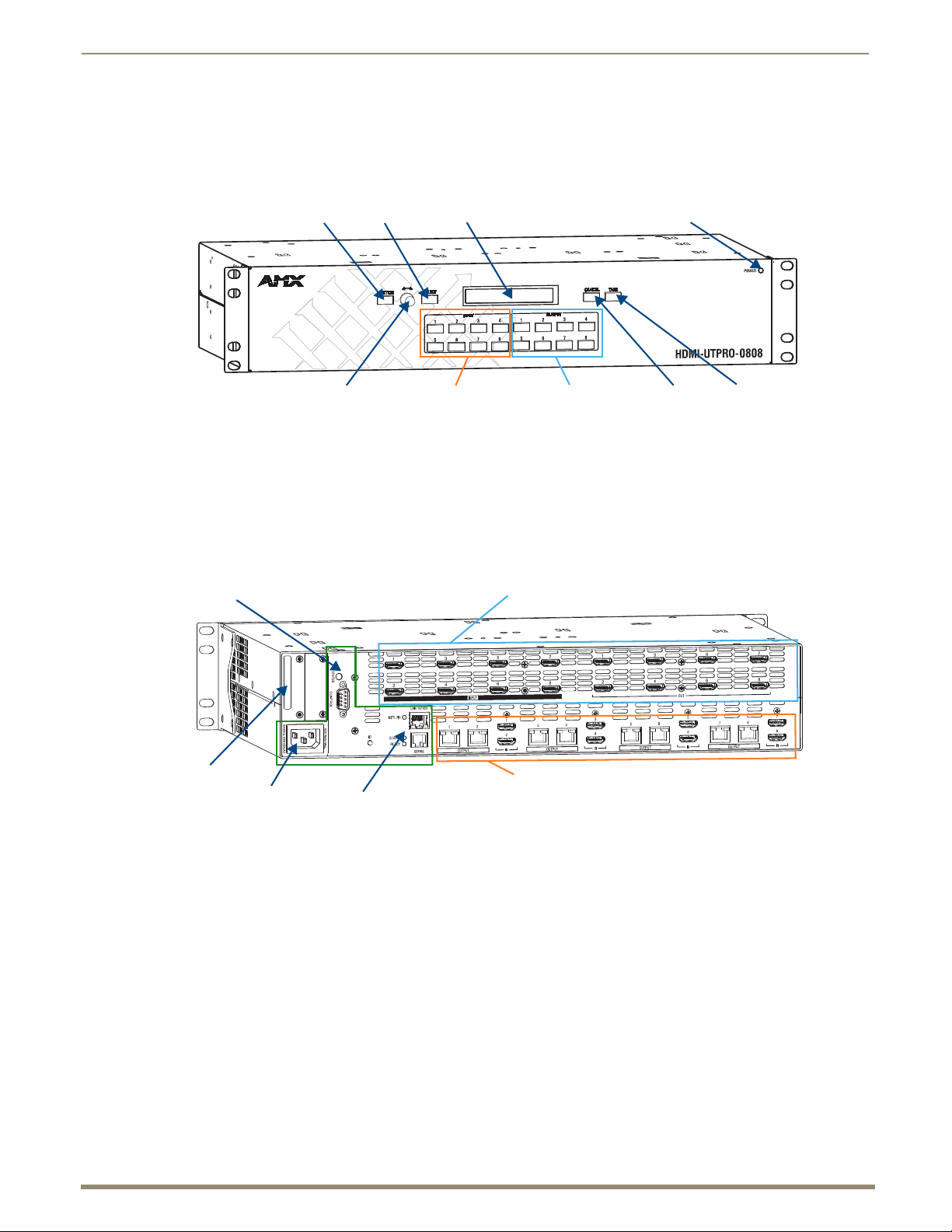
Input Keys (1-8)
Power LED
Cancel Key Take Key
LCD
Control Dial
Select KeyFunction Key
Output Keys (1-8)
CPU and serial control
Power receptacle
HDMI matrix switching connectors
HDMI and UTP (RJ-45) transport connectors
Ethernet and serial control and configuration
Serial number
HDMI UTPro Front Panel Components
The HDMI UTPro comes standard with a front control panel. Even when another method of control is primary, the
control panel can be used for system verification, redundant control, and troubleshooting. Control panel operation is
covered starting on page 44.
FIG. 1 Front view HDMI UTPro
HDMI UTPro Rear Panel Components
All connectors are on the rear panel, which is laid out in three main areas.
Power, control and configuration on the left
HDMI matrix switching connectors on the top
HDMI and UTP (RJ-45) transport connectors on the bottom
FIG. 2 Rear view HDMI UTPro
The following sections briefly introduce the hardware on the rear panel.
Power Receptacle
The universal power receptacle is in the lower left hand corner on the rear of the enclosure. Maximum power
specifications are on the power receptacle. The power receptacle accepts all major international standard power sources.
(Standard US power cords are provided for installations within the US.)
The fuse is internal and is not field serviceable. If you believe the fuse needs to be replaced, contact technical support
(see page 43).
Page 13
Overview and General Specifications
13
Instruction Manual – HDMI-UTPRO-0808
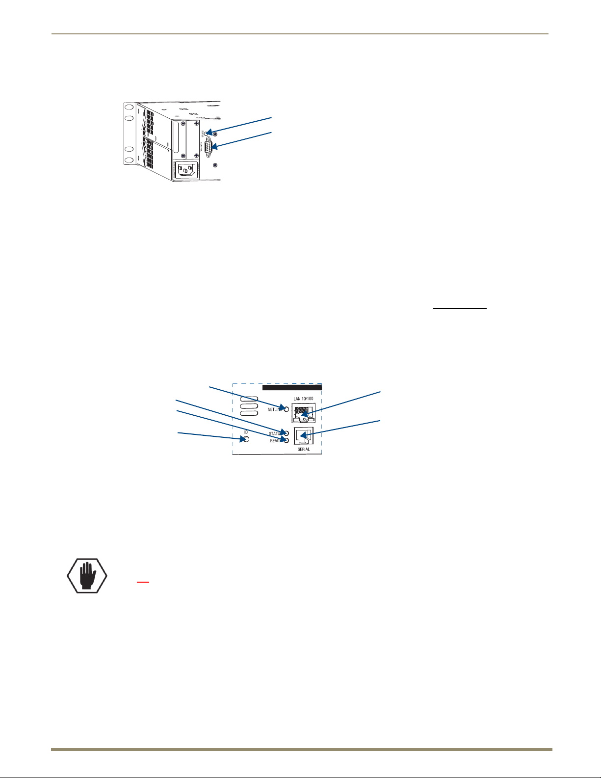
Control (DB-9) port
Status LED
LAN 10/100 (Ethernet) port
Serial (RJ-12) port
ID push button
NetLinx LED
Status LED
Ready LED
CPU / Serial Control
The CPU is to the right of the power receptacle on the rear of the enclosure.
FIG. 3 Control port (DB-9 connector)
CPU Components:
Status LED – system status indicator
Control port – serial port (DB-9) for attaching an external serial control device (see page 39)
The Control (RS-232) port* can be used for matrix switching control functionality as an alternative to Native NetLinx
control. We recommend using only one at a time, with native NetLinx as the preferred method and the RS-232 port as a
backup because commands on the Native NetLinx connection will be accepted on a first come/first served basis (which
may conflict with the BCS commands).
* BCS (Basic Control Structure) commands are sent as ASCII characters through the RS-232 port. For information on
BCS commands, see the Instruction Manual – BCS Basic Control Structure Protocol at www.amx.com
.
Ethernet Plus Serial Control and Configuration
The Ethernet connector and its LED along with the Serial (RJ-12) connector and its LEDs are to the right of the power
receptacle. An ID push button (not required for installation) which places the system in ID mode for setting the NetLinx
ID (device only) is to the left of the Serial port. The ID push button is used in conjunction with NetLinx Studio; see
NetLinx Studio documentation for details.
FIG. 4 LAN 10/100 connector, Serial connector, LEDs, and ID push button
Ethernet and Serial Components
ID push button (not required for installation) – Places the system in ID mode.
LAN 10/100 (Ethernet) port – provides 10/100 BaseT connectivity.
NetLinx LED – blinks at 5 sec. intervals when connection to NetLinx Master is established.
Serial (RJ-12) – provides serial connectivity for an external device control (e.g., a Blu-Ray).
Status LED – non-functional.
Ready LED – solid green indicates that NetLinx has fully booted and is ready.
Caution: On some AMX matrix switchers the 10/100 port (RJ-45) is used for linking enclosures.
attempt to link the HDMI UTPro Matrix Switcher to other enclosures of any type.
Do not
Page 14
Overview and General Specifications
14
Instruction Manual – HDMI-UTPRO-0808
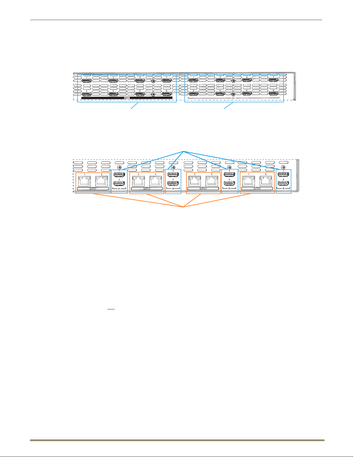
HDMI matrix switching output connectorsHDMI matrix switching input connectors
HDMI transport input connectors
UTP (RJ-45) transport output connectors
HDMI Matrix Switching Connectors (1-8 HDMI Inputs and 1-8 HDMI Outputs)
The HDMI matrix switching connectors (8 inputs left and 8 outputs right) are on the top as viewed from the rear of the
enclosure. Information on cabling these connectors is on page 29, and special HDMI concerns and considerations are
covered in the “Setting Up HDMI Systems” chapter (see page 60).
FIG. 5 HDMI matrix switching connectors
HDMI and UTP Transport Connectors (1-8 HDMI Inputs and 1-8 RJ-45 Outputs)
FIG. 6 HDMI and UTP transport connectors
The UTP transport connectors are on the bottom as viewed from the rear of the enclosure.
Important: For detailed cabling information for the HDMI and UTP transport connectors, see page 29.
Transport Connectors
HDMI transport input connectors (IN 1-8) – accept cables from the HDMI matrix switching outputs
(OUT 1-8); be sure each patch cable is connected to corresponding numbers (1 to 1, 2 to 2, etc.). The number
for the HDMI matrix switching output connector and number for the HDMI transport input connector must
match for each patch cable.
UTP (RJ-45) transport output connectors (OUT 1-8) – provide connectivity for up to 8 HDMI-UTPRO-RX
Receivers (FG1403-20) via UTP cable.
Important: Do not
use the UTP transport connectors for connecting to a standard Ethernet network.
System Serial Number
The system’s serial number is normally located in two places on the enclosure. When viewed from the rear, one serial
number label is on the left above the power receptacle. The second serial number label is on the left side of the enclosure
at the bottom edge near the power receptacle. The label on the side will also have the enclosure number (referred to as
the chassis number).
Before installation, we recommend recording the system’s serial number in an easily accessible location.
Page 15

Overview and General Specifications
15
Instruction Manual – HDMI-UTPRO-0808
HDMI-UTPRO-RX Receiver
The HDMI-UTPRO-RX Receiver is used in conjunction with the HDMI UTPro 8x8 to assist in the transport of HDMI
signals over UTP cable. Cables from the HDMI UTPro are connected to the HDMI-UTPRO-RX Receivers, which in
turn are connected to the destination devices. In addition, the Receiver has ports for serial communication and IR control
(FIG. 7).
The size of the Receiver makes it easy to mount near or behind a high definition monitor. A Surface Mounting Bracket
kit (FG525) is available for this purpose. The Receivers should not be stacked to allow for adequate cooling. If mounting
in a rack using some type of tray, a minimum of one empty rack unit above and below is recommended (see the section
on “Airflow Restriction” on page 24).
FIG. 7 HDMI-UTPRO-RX Receiver
HDMI-UTPRO-RX Components
The front of the HDMI-UTPRO-RX Receiver has an LED Power indicator.
The rear components on the HDMI-UTPRO-RX Receiver include the following from left to right:
Power jack – 12 V to 24 V DC power jack (desktop power supply provided*)
Serial port (RJ-12) – optional serial communication for control of the monitor (see page 16)
IR Rx port – supports generation of NetLinx key presses (channel events) from AMX remote controls
(see “IR Control” on page 16)
IR Tx port – supports wired control of connected IR devices (see “IR Control” on page 16)
HDMI Out connector – HDMI connector connects via HDMI cable to the destination device
Input connector – RJ-45 connector connects via UTP cable to an RJ-45 output connector on the HDMI UTPro
* The automatically adjusting universal 110/220 IEC power supply is ENERGY STAR® qualified to ensure maximum
efficiency and savings.
Page 16

Overview and General Specifications
16
Instruction Manual – HDMI-UTPRO-0808
IR Control (Optional)
Compatible IR Control Options: UDM-RC05 or MIO-R1
The following three items are required for IR control via the HDMI-UTPRO-RX Receiver. (These items are not included
with the HDMI UTPro but must be ordered separately.)
UDM-RC05 – The UDM-RC05 (FG1402-70) remote control can be used as a control interface to a UTPro
system. If this remote is selected, the key presses will generate channel events from the receiver which may
be processed in a connected master and used in the same way as touch panel button presses.
Or
MIO-R1 – The Mio Modero
®
R-1 Remote (FG147) is an IR remote control unit that can communicate with
an HDMI-UTPRO-RX Receiver and provides custom control features. (Requires the KeypadBuilder
application for programming of the remote.)
IR03 – External IR Receiver Module (FG-IR03). The IR03 connects to the IR Rx jack on the
HDMI-UTPRO-RX, allowing IR signals to be received from a compatible IR remote control like the
UDM-RC05. The IR03 allows the HDMI-UTPRO-RX to be placed behind the display device if desired.
IR01 – IR Emitter Module (FG-IR01). The IR01 connects to the IR Tx jack on the HDMI-UTPRO-RX,
allowing IR signals to be sent to the display device.
Serial Control (Optional)
The Serial port on the HDMI-UTPRO-RX Receiver is an RJ-12 connector and displays in NetLinx Studio as Port 2 of
the Receiver. This port may require an adapter cable to connect to the external serial device under control. The
information for this port starts on page 36. Cable adapter information is on page 37. The RJ-12 pinout is on page 38.
Serial Port - Default Communication Settings
The default serial settings are listed in the table below. The settings can be altered by sending
SEND_COMMANDs to Port 2 of the Receiver (see page 91).
Default Serial Settings
Baud Rate 9600
Data Bits 8
Parity None
Stop Bits 1
Flow Control None
Page 17

Overview and General Specifications
17
Instruction Manual – HDMI-UTPRO-0808
HDMI-UTPRO-0808 Product Specifications
HDMI-UTPRO-0808 Specifications
Parameter Value
Approvals UL, cUL, CE, FCC Class A, RoHS, WEEE
Humidity 0 to 90% non-condensing
Operational Temperature 32° F to 113° F (0° C to 45° C)
Storage Temperature -22° F to 158° F (-30° C to 70° C)
AC Power* 100 VAC to 240 VAC, single phase (50 Hz to 60 Hz)
Power Consumption (max.) 110 Watts, fully loaded
Thermal Dissipation (max.) 375 BTU/hr, fully loaded
MTBF 71,000 hours
Dimensions
Depth
Width with mounting ears
Width without mounting ears
Height
Weight Approximately 13 lb. (5.9 kg)
Shipping Weight 46 lbs (20.87 kg) for complete system kit including 8 RXs (2 shipping boxes)
Front Panel Components
Function Key The Function Key accesses the Function menu on the LCD.
Control Dial The Control Dial scrolls through menu options and adjusts values, such as global preset
Select Key The Select Key enters a menu selection and can be used to execute presets.
LCD Display The LCD displays the Function menu. The Function menu and its submenus access the
Cancel Key The Cancel Key clears an incomplete operation and returns the display to the beginning
Take Key The Take Key instructs the system to execute or disconnect a switch.
Input/Output 1-8 Keys Input and Output Keys (1-8) correspond to the input and output connections on the rear
Power LED The Power LED illuminates to indicate the unit is receiving power.
Rear Panel Components
Power Connector The universal power receptacle accepts all major international standard power sources.
Control Port (CPU) Bi-directional RS-232
Status LED (CPU) System status indicator
ID Push Button Places the system in NetLinx Device ID assignment mode (requires NetLinx Studio).
LAN 10/100 port (Ethernet) Native NetLinx Device
Approximately 12 in. (30.5 cm)
18.9 in. (48.0 cm)
17.4 in. (44.2 cm)
3.5 in. (8.9 cm) (2 RU)
numbers.
different modes and lists used to control the system.
of a submenu or list.
of the enclosure. These keys are used to select the input and outputs for routing source
signals to destination devices as well as for status and other operations such as locking
and unlocking the control panel.
Note: The rating along the sides of the power connector contains important installation
information.
Baud rates of 9600, 19200, 38400, 57600 (default 9600)
DB-9 connector
Not required for installation.
TCP/IP (LAN 10/100)
Serves built-in WebConsole
Auto MDI/MDI-X cross-over
RJ-45 connector
* The fuse is internal and is not field serviceable. If you believe the fuse needs to be replaced, contact technical support
(see page 43).
Page 18

18
Instruction Manual – HDMI-UTPRO-0808
Compatible IR
equipment
Overview and General Specifications
Rear Panel Components (continued)
Serial Port (RJ-12) • Bi-directional RS-232
• Baud rates 115200, 57600, 38400, 19200, 9600, 4800, 2400, 1200 (default 9600)
• RJ-12 connector
NetLinx LED Blinks at 5 second intervals when a connection to a NetLinx Master is
established.
Status LED Non-functional.
Ready LED Solid green indicates that NetLinx has fully booted and is ready.
HDMI Matrix Switching Input
and Output Connectors
HDMI Transport Input
Connectors
UTP RJ-45 Transport Output
Connectors
Other AMX Equipment
Included Accessories • 8 HDMI-UTPRO-RX Receivers (FG1403-20); for specifications, see page 22
Compatible / Optional
Equipment
The HDMI matrix switching connectors are located on the upper-half of the rear panel.
The HDMI input and output connectors allow for the use of cables from source and
destination devices with HDMI connectors.
These connectors also have local DDC (Display Data Channel) support with plug-and-
play information provided by the HDMI UTPro.
• HDMI inputs (IN 1-8) accept inputs from up to 8 HDMI source devices.
• HDMI outputs (OUT 1-8) connect to HDMI inputs (INPUT 1-8) on the bottom
(see HDMI Transport Input Connectors below).
Note: Refer to the “Digital Video - HDMI Specifications” table for complete specifications
(see page 19).
The HDMI inputs (INPUT 1-8) accept HDMI patch cables (provided) from the HDMI
matrix switching outputs (OUT 1-8).
The RJ-45 outputs (OUTPUT 1-8) provide connectivity for up to 8 HDMI-UTPRO-RX
Receivers (FG1403-20) via UTP cable.
• 8 desktop power supplies (12 V 1.25 A) with power cord (FG1090-155)
• 8 connection cables (connect between HDMI matrix switching outputs and the HDMI
transport inputs)
• 1 power cord (standard US power cords are provided for installations within the US)
• 2 rack mounting brackets for the enclosure
Note: No A/V interface cables are supplied.
• UDM-RC05 IR Remote Control (FG1402-70)
• IR01 Infrared Emitter Module (FG-IR01)
• IR03 External Infrared Receiver Module (FG-IR03)
• MIO-R1 Mio Modero
• RS-232 Serial (DB-9/RJ-12) connection cable (FG-RS01)
• RS-232 Serial (DB-9/RJ-12) connection cable kit with adapters (FG-RS01K)
• 6 ft. (1.83 m) Ethernet crossover cable (CA2179-02)
• Surface Mounting Bracket kit - for Receivers (FG525)
®
R-1 Remote Control (FG147)
Page 19

Overview and General Specifications
19
Instruction Manual – HDMI-UTPRO-0808
Digital Video – HDMI Specifications
Digital Video – HDMI Specifications
Compatible Formats HDMI, HDCP, DVI (DVI is supported with appropriate conversion cable)
Supported Twisted-Pair Cable Types Cat5e, Cat6/6e, Cat6a, Cat7, STP, FTP
Supported Twisted-Pair Cable
Length
Transport Layer Throughput (max.) 10.2 Gbps
Video Data Rate (max.) 4.95 Gbps
Video Pixel Clock (max.) 165 MHz
Progressive Resolution Support 480p, 576p, 720p, 1080p and 640x480 through 1920x1200 @ 60 Hz
Interlaced Resolution Support 480i, 576i, 1080i
Audio Format Support Dolby Digital,* DTS,* L-PCM
Audio Resolution 16 bit to 24 bit
Audio Sample Rate 32 kHz, 44.1 kHz, 48 kHz, 96 kHz,** 192 kHz**
Signal Type Support HDMI
DDC/EDID Support EDID provided by the HDMI UTPro enclosure
HDCP Support Yes, full matrix HDCP support (includes any input to any or all outputs)
CEC Support No
Input Voltage (nominal) 1.0 Vpp differential
Output Voltage (nominal) 1.0 Vpp differential
Output Re-clocking (CDR) Yes
Output +5 V DDC pin 50 mA max. per output port
HDMI Propagation Delay 3 uS
Connectors HDMI Type A female
• Up to 328 ft. (100 m); cable quality required in order to meet 100 meter
distance should meet ANSI/TIA/EIA 568A-5 specification or better specification
and be rated for 250 MHz or better.
• For cable runs approaching the 100 meter limit, Cat6/6e, Cat6a, or Cat7 is
recommended.
• It is recommended that the cabling between AMX systems/devices be a
uniform run of solid core cabling with no patch cables or extensions.
• If a patch cable is required (e.g., between a patch panel and an AMX device),
the patch cable should be limited to 5 meters total on each end.
• Best results have been seen using a Cat6 coupling device for attaching the
cables together, even when using lower rated Cat5e cabling.
• If running cables together, then screened cabling should be used to reduce
crosstalk.
• If running Cat5e/6 cables together in a bundle, they can only be coupled for a
distance of up to 60 meters before they must be separated over the remainder
of the run. Cat6a and Cat7, which are shielded by definition, can be bundled for
the entire 100 meter run.
(1600x1200 @ 60 Hz and higher requires reduced blanking)
DVI-D (single link with cable adapter)
EDID is user re-programmable
AMX HDCP InstaGate
®
Technology
* Dolby Digital and DTS support up to 48 kHz, 5.1 channels.
** Two channel L-PCM support up to 192 kHz at 1080p (50 Hz, 59 Hz, 60 Hz).
Two channel L-PCM support up to 96 kHz at 720p, (50 Hz, 59 Hz, 60 Hz), 1080p (24 Hz, 25 Hz, 30 Hz, 50 Hz, 59 Hz,
60 Hz), 1080i (50, 59, 60 fields).
Two channel L-PCM support up to 48 kHz at all resolutions.
Page 20

Overview and General Specifications
20
Instruction Manual – HDMI-UTPRO-0808
EDID Resolutions Supported through Local DDC for HDMI Connectors
Standard and established timings are provided in the following tables along with detailed timing blocks.
Note: The EDID can be re-programmed to support additional resolutions through the local DDC using the
EDID Programmer (see page 101).
Standard Timings
Standard Timing
Resolution Refresh Rate Max.
Identification
ID 1 1920x1080 (This is the preferred timing
identified in the EDID.)
ID 2 1680x1050 60 Hz
ID 3 1600x1200 60 Hz
ID 4 1280x800 60 Hz
ID 5 1280x720 60 Hz
ID 6 1280x1024 60 Hz
ID 7 1360x768 60 Hz
ID 8 1440x900 60 Hz
ID 9 2048x1152 60 Hz
ID 10 1600x900 60 Hz
ID 11 1400x1050 60 Hz
ID 12 1280x960 60 Hz
60 Hz
Established Timings
Resolution Refresh Rate
640x480 60 Hz, 67 Hz, 72 Hz, 75 Hz
800x600 56 HZ, 60 Hz, 72 Hz, 75 Hz
832x624 75 Hz
1024x768 60 Hz, 70 Hz, 75 Hz, 87 Hz
1280x1024 75 Hz
1152x870 75 Hz
Detailed Timing Blocks
1920x1080 60 Hz, 148.5 MHz
1920x1080 60 Hz, 138.5 MHz
1920x1080 60 Hz, 141.5 MHz
1920x1200 60 Hz, 158.25 MHz
1920x1200 60 Hz, 154.0 MHz
Resolution Refresh Rate
Page 21

21
Instruction Manual – HDMI-UTPRO-0808
CEA Video Information Code (VIC) Formats
VIC # Resolution Refresh Rate and Aspect Ratio
VIC = 1 640x480p 59.94/60 Hz, 4:3
VIC = 2 720x480p 59.94/60 Hz, 4:3
VIC = 3 720x480p 59.94/60 Hz, 16:9
VIC = 4 1280x720p 59.94/60 Hz, 16:9
VIC = 5 1920x1080i 59.94/60 Hz, 16:9
VIC = 6 720(1440)x480i 59.94/60 Hz, 4:3
VIC = 7 720(1440)x480i 59.94/60 Hz, 16:9
VIC = 14 1440x480p 59.94/60 Hz, 4:3
VIC = 15 1440x480p 59.94/60 Hz, 16:9
VIC = 16 Native 1920x1080p 59.94/60 Hz, 16:9
VIC = 17 720x576p 50 Hz, 4:3
VIC = 18 720x576p 50 Hz, 16:9
VIC = 19 1280x720p 50 Hz, 16:9
VIC = 20 1920x1080i 50 Hz, 16:9
VIC = 21 720(1440)x576i 50 Hz, 4:3
VIC = 22 720(1440)x576i 50 Hz, 16:9
VIC = 29 1440x576p 50 Hz, 4:3
VIC = 30 1440x576p 50 Hz, 16:9
VIC = 31 1920x1080p 50 Hz, 16:9
VIC = 32 1920x1080p 23.97/24 Hz, 16:9
VIC = 33 1920x1080p 25 Hz, 16:9
VIC = 34 1920x1080p 29.97/30 Hz, 16:9
VIC = 39 1920x1080i 50 Hz, 16:9
VIC = 41 1280x720p 100 Hz, 16:9
VIC = 42 720x576p 100 Hz, 4:3
VIC = 43 720x576p 100 Hz, 16:9
VIC = 44 720(1440)x576i 100 Hz, 4:3
VIC = 45 720(1440)x576i 100 Hz, 16:9
VIC = 47 1280x720p 119.88/120 Hz, 16:9
VIC = 48 720x480p 119.88/120 Hz, 4:3
VIC = 49 720x480p 119.88/120 Hz, 16:9
Overview and General Specifications
Audio Data Block
Channels Sampling Frequency
2 Channel L-PCM 32, 44.1, 48, 88.2, 96, 176.4, 192 kHz sampling frequency at 16, 20, or 24 bits
AC-3 (Dolby Digital) 6 Channels (5.1) 48 kHz sampling frequency
DTS 6 Channels (5.1) 48 kHz sampling frequency
per sample
Page 22

Overview and General Specifications
22
Instruction Manual – HDMI-UTPRO-0808
HDMI-UTPRO-RX Specifications
HDMI-UTPRO-RX Specifications
Parameter Value
Approvals UL, cUL, CE, FCC Class A, RoHS, WEEE
AC Power 100 VAC to 240 VAC, single phase (50 Hz to 60 Hz)
DC Power 12 V to 24 V (+/-10%, desktop power supply included*)
Power Consumption 12 Watts, fully loaded
Thermal Dissipation 41 BTU/hr, fully loaded
Operational Temperature 32° F to 113° F (0° C to 45° C)
Humidity 0 to 90% non-condensing
MTBF 203,000 hours (combined set of 8 RX modules)
Serial Port Bi-directional RS-232
IR Control (Optional) IR Rx Jack: 3.5 mm input port for connection of an IR03 Receiver module (see page 15).
HDMI Output Connector HDMI connector connects via HDMI cable to destination device
RJ-45 Input Connector RJ-45 connector connects via UTP cable to RJ-45 output connector on the
Dimensions 3.8 in. (9.69 cm) depth
Weight per Module Approximately 1.5 lbs (0.68 kg) (for shipping weight, see enclosure specifications)
Baud rates 115200, 57600, 38400, 19200, 9600, 4800, 2400, 1200 (default 9600)
RJ-12 connector
“MIO” protocol is loaded as the default.
IR Tx Jack: 3.5 mm output port for connection of an IR01 Emitter module (see page 15).
The *.IRL file must be loaded for the destination device (see page 98).
For information on compatible IR remote controls, see page 16 and page 18.
HDMI-UTPRO-0808 enclosure
6 in. (15.24 cm) width
1 in. (2.54 cm) height
* We recommend using a regulated power supply for the HDMI-UTPRO-RX. If you exceed the specified voltage level for
the power jack on the RX, the warranty will be void.
AMX reserves the right to modify its products and their specifications without notice.
Common Applications
Whether your displays are across the room, on the other side of the house, or in a classroom down the hall, your sources
can be distributed to up to 8 different displays located remotely. In addition, since UTPRO signals are carried over
commonly available Unshielded Twisted Pair (UTP) cable, the HDMI-UTPRO-0808 is also an extremely cost effective
solution to install.
Configuration Information and Control Options
Routing Configuration Information
The HDMI UTPro systems specify two identical virtual matrices for switching signals: VM 0 = All and VM 1 = Video.
These two VMs function the same for this product. Additional VMs can be created with XNConnect configuration
software as one way to deal with sources with limited sink support (see page 65 and page 119).
Configuration Options
The WebConsole can be used to configure the master connection for the HDMI UTPro, as well as networking
and time settings. Refer to the “HDMI UTPro WebConsole” chapter on page 69 for details.
Use NetLinx SEND_COMMANDs to configure and control the HDMI UTPro. Refer to the “HDMI UTPro
NetLinx Programming” chapter on page 83 for programming details.
Page 23

Overview and General Specifications
23
Instruction Manual – HDMI-UTPRO-0808
Control Options
HDMI UTPro systems support two main protocols: TCP/IP and XNNet (protocol used by control panel). Several control
options are available. Multiple control methods can be used on the same system.
Native NetLinx Interface
The HDMI UTPro can be integrated with any NetLinx Central Controller and appears in NetLinx Studio (Version 3 or
higher is required) as a NetLinx device.
Front Control Panel
The HDMI UTPro comes standard with a front control panel. Even if another method of control is preferred, the control
panel can be used for system verification, redundant control, and troubleshooting.
AMX Control Devices
The HDMI UTPro is compatible with a number of AMX control devices. For control programming information, see the
instruction manual for the specific interface.
Third-Party Controllers
A third-party controller can also be attached to the Control (DB-9 serial) port on an HDMI UTPro enclosure (note that
this port cannot provide the additional NetLinx functionality which is available through the LAN 10/100 port). If using
a third-party controller, see the controller documentation for operating instructions.
System Diagnostics (Programmer’s Interface)
The HDMI UTPro displays system information in its splash screen for diagnostic purposes. The information indicates
the current status and well-being of the system components. The splash screen can be accessed using a terminal
emulation program (e.g., TeraTerm, PuTTY, or HyperTerminal). For additional information, see Appendix B on
page 106.
Page 24

24
Instruction Manual – HDMI-UTPRO-0808
Installation and Setup
Site Recommendations
When placing the enclosure, follow the recommendations and precautions in this section to reduce potential installation
and operation hazards.
Environment
Choose a clean, dust free, (preferably) air-conditioned location.
Avoid areas with direct sunlight, heat sources, or high levels of EMI (Electromagnetic Interference).
To make control panel operations easier, mount the enclosure with the control panel in the rack at eye level.
Chassis Accessibility
Make sure the front and rear panels of the enclosure are accessible, so that you can monitor the LED indicators. Leaving
adequate clearance at the rear will also allow for easier cabling and service.
Power
The source’s electrical outlet should be installed near the router, easily accessible, and properly grounded. Power should
come from a building branch circuit. We recommend using a dedicated line for the system’s power. To avoid an
overload, note the power consumption rating of all the equipment connected to the circuit breaker before applying
power.
Installation and Setup
General Hazard Precautions
These recommendations address potential hazards that are common to all installations:
Elevated Operating Temperature
The maximum rated ambient temperature for the HDMI UTPro enclosure is 113° F (45° C).
All equipment should be installed in an environment compatible with the manufacturer’s maximum rated ambient
temperature. In a closed or multi-unit rack assembly, the operating ambient temperature of the rack environment may be
greater than the ambient room temperature.
Caution: To protect the equipment from overheating, do not operate in an area that exceeds 113° F (45° C)
and follow the clearance recommendations in the “Caution” below for adequate airflow.
Airflow Restriction
The HDMI UTPro enclosure is designed to adequately dissipate the heat it produces under normal operating conditions;
however, this design is defeated when high heat producing equipment is placed directly above or below the enclosure.
The previous statement also applies to the HDMI-UTPRO-RX Receivers.
Caution: To prevent overheating, avoid placing high heat producing equipment directly above or below the
enclosure or the Receivers. The enclosure requires a minimum of one empty rack unit above and below
(three empty rack units are recommended). The Receivers should not be stacked to allow for adequate
cooling. If mounting in a rack using some type of tray, a minimum of one empty rack unit above and below is
recommended. Verify that the openings on the sides of the enclosure and the front and back of the
Receivers are not blocked and do not have restricted air flow.
Mechanical (Rack) Loading
When installing equipment in a rack, distribute the weight to avoid uneven mechanical loading.
Circuit Overloading
When connecting the equipment to the supply circuits, be aware of the effect that overloading the circuits might have on
over-current protection and supply wiring.
Page 25

Installation and Setup
25
Instruction Manual – HDMI-UTPRO-0808
Reliable Earthing (Grounding)
Reliable earthing of rack-mounted equipment should be maintained. If not using a direct connection to the branch circuit
(e.g., plugging into a power strip), pay particular attention to supply connections.
Caution: We recommend attaching all power cords to a surge protector and/or an AC line conditioner.
Unpacking
The HDMI-UTPRO-0808 Kit is shipped in two boxes (one contains the HDMI UTPro and the other contains the
HDMI-UTPRO-RX units). The invoice is sent separately; a packing slip is attached to the outside of each box.
The complete kit includes following items:
HDMI-UTPRO-0808 Kit (enclosure, 8 receivers, 8 desktop power supplies)
Standard US power cord (if shipped within the US)
Rack ears with 8 screws per kit
Other enclosure products as needed
The documentation includes:
AMX HDMI-UTPRO-0808, Twisted Pair Dist Kit Quick Start Guide
Shipping boxes are marked as “Box __ of __,” where the first blank is the box number and the second blank is the total
number of boxes in the shipment.
Unpacking Tips
Before fully unpacking the enclosure, inspect the shipping box for any signs of damage.
If a box is partially crushed or any sides have been broken open, notify the shipping agency immediately and
contact your AMX representative (see the warranty at www.amx.com
Once unpacking is complete, closely check the physical condition of the enclosure.
Collect all documentation.
Note: Please save the original shipping container and packing materials. AMX is not responsible for damage
caused by insufficient packing during return shipment to the factory. Shipping boxes are available; contact
your AMX representative for details.
).
Page 26
Installation and Setup
26
Instruction Manual – HDMI-UTPRO-0808
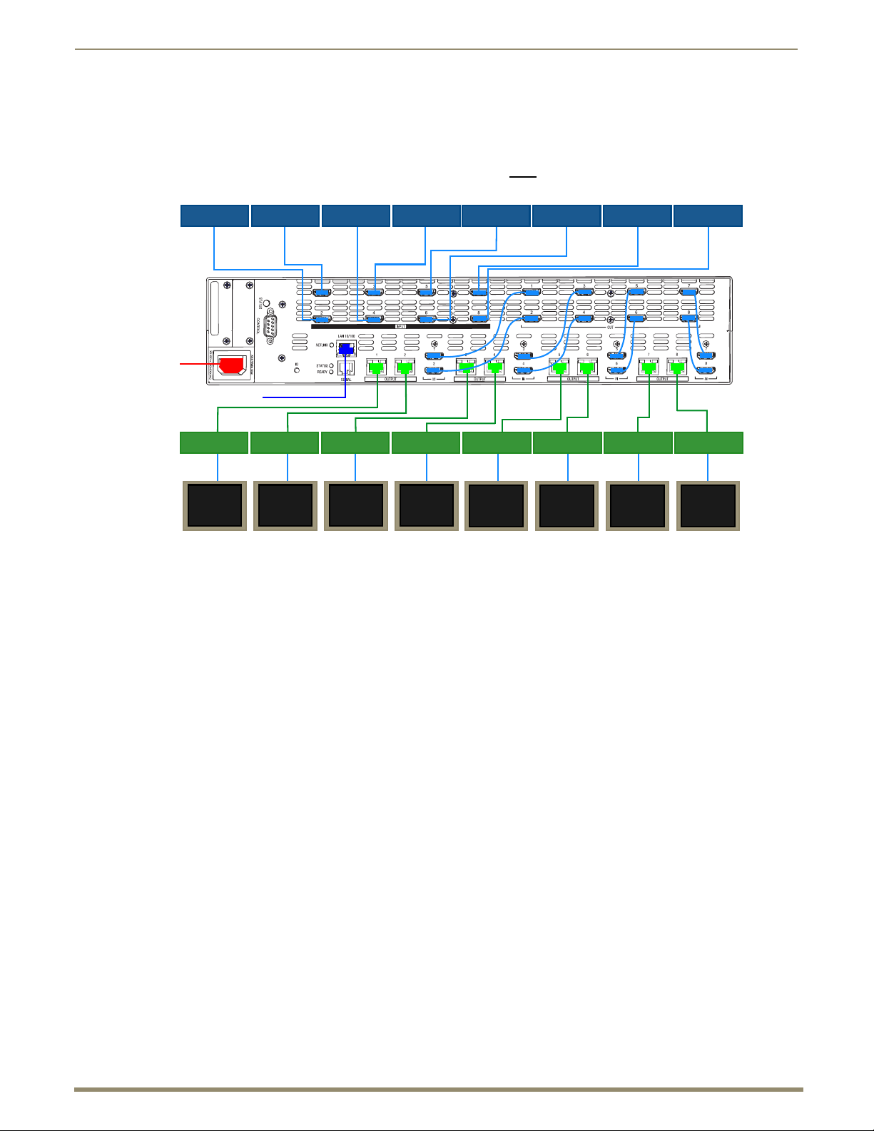
AC
Display
Device
Display
Device
Display
Device
Display
Device
HDMI
Source Device
HDMI
Source Device
HDMI
Source Device
HDMI
Source Device
HDMI
Source Device
HDMI
Source Device
HDMI
Source Device
HDMI
Source Device
Ethernet cable (to LAN)
HDMI-UTPRO-RX HDMI-UTPRO-RX HDMI-UTPRO-RX
Display
Device
Display
Device
Display
Device
Display
Device
HDMI HDMI HDMI HDMI HDMI HDMI HDMI HDMI
UTP cable UTP cable UTP cable UTP cable
UTP cable UTP cable UTP cable
UTP cable
HDMI HDMI HDMI HDMI HDMI HDMI HDMI HDMI
HDMI-UTPRO-RX
HDMI-UTPRO-RX HDMI-UTPRO-RX HDMI-UTPRO-RX HDMI-UTPRO-RX
Power
System Diagram
The diagram in FIG. 8 illustrates a basic A/V distribution system using an HDMI-UTPRO-0808 Matrix Switcher and
eight HDMI-UTPRO-RX Receivers.
Important: Each HDMI matrix switching output connector must be connected (with HDMI patch cable provided) to its corresponding HDMI transport input connector (1 to 1, 2 to 2, etc.).
FIG. 8 System Diagram
Rack Installation and System Setup
The HDMI UTPro enclosure can be mounted in a standard EIA 19 in. (48.26 cm) rack. Rack installation ears are
included, and directions for mounting the rack ears are included in the rack installation instructions on page 28.
Important: The system requires at least one empty rack unit above and below the enclosure to allow
adequate airflow; three empty rack units are recommended.
Required items for rack installation:
Enclosure
Standard EIA 19 in. (48.26 cm) rack
Rack ears with 8 screws per kit
Screwdriver
Screws that fit your rack for mounting the enclosure
Standard US power cord (if shipped within the US)
Optional items for rack installation:
Surge-protector(s) – highly recommended
A laptop computer or PC with a null modem cable (for communication with the HDMI UTPro via the
Control / RS-232 port)
Page 27
Installation and Setup
27
Instruction Manual – HDMI-UTPRO-0808
Installation Recommendations
Write the system’s serial number in an easily accessible location before installing the HDMI UTPro
The system’s serial number is located in two places on the enclosure: on the left rear and on the left side of
the enclosure near the power receptacle. The serial number also displays at the end of the product name in
NetLinx Studio’s ZeroConfig tree.
Use an earth-grounded power cord / system with the HDMI UTPro.
Attach all power cords to a single surge protector and/or an AC line conditioner.
Apply power to the HDMI UTPro enclosure before applying power to its source and destination devices.
in a rack.
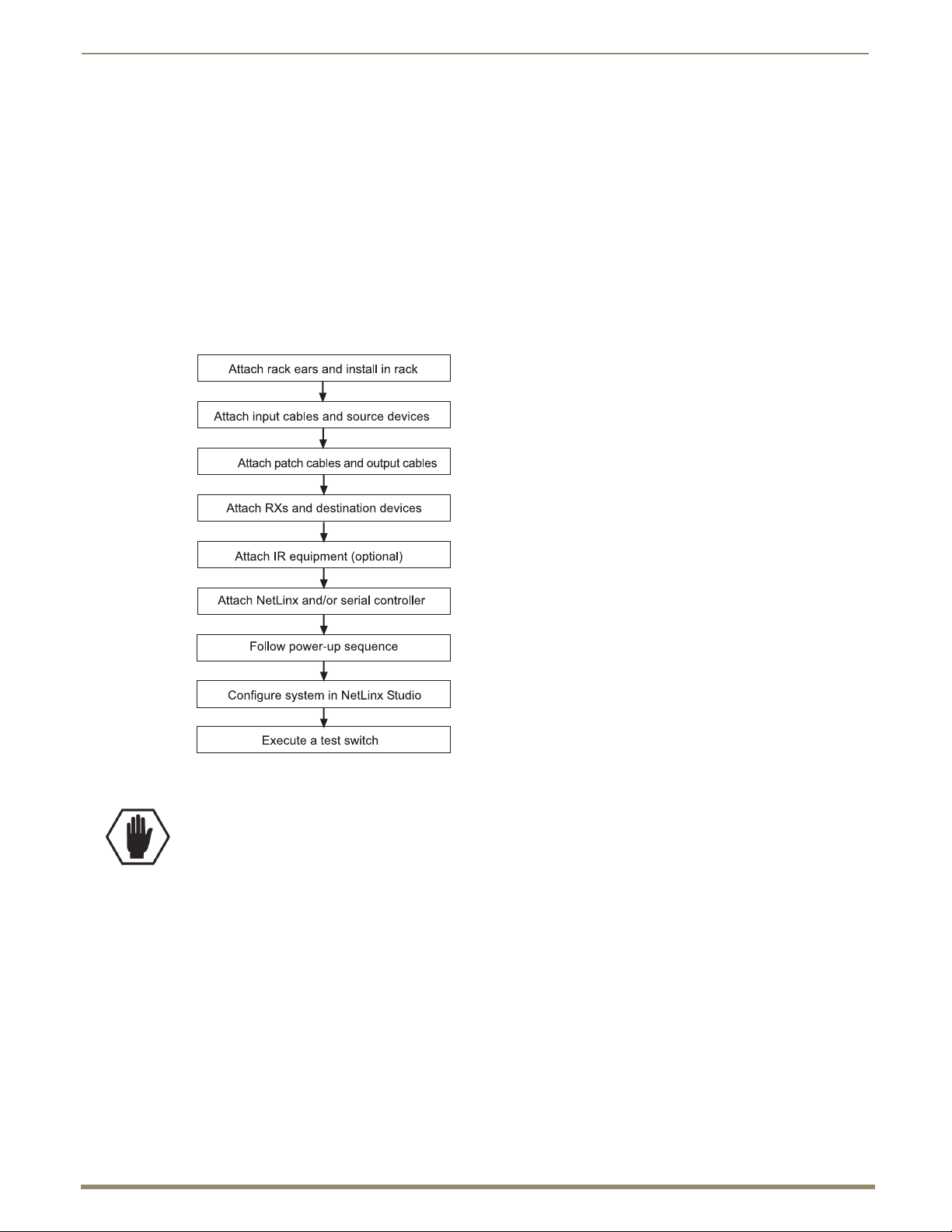
Installation Procedure
A flow chart showing the installation sequence is in FIG. 9. The procedure on page 28 provides general steps with
references to detailed information found in later sections of the manual.
FIG. 9 Installation procedure
Caution: To prevent overheating, avoid placing high heat producing equipment directly above or below
the enclosure or the Receivers. The enclosure requires a minimum of one empty rack unit above and below
(three empty rack units are recommended). Stacking Receivers will not allow the units adequate cooling.
If mounting in a rack using some type of tray, a minimum of one empty rack unit above and below is
recommended. Verify that the openings on the sides of the enclosure and the front and back of the
Receivers are not blocked and do not have restricted air flow.
Page 28
Installation and Setup
28
Instruction Manual – HDMI-UTPRO-0808
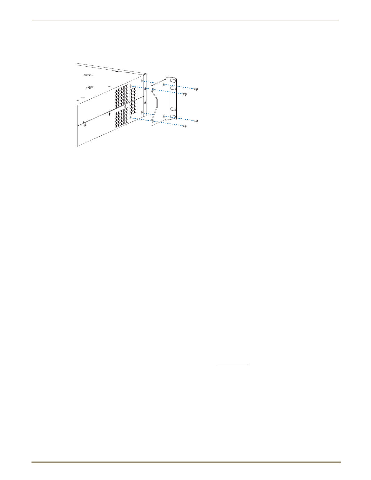
To install and set up an HDMI UTPro in a rack:
1.
Attach the rack ears per FIG. 10 (ears provided).
FIG. 10 Attach rack ears to sides of enclosure
2. Place the enclosure in the rack and attach front-mounting screws to hold it firmly in place.
Tip: When placing an enclosure, keep in mind that the optimal viewing angle for a control panel is eye level.
3. Attach the source devices; see “Attaching Cables for Switching/Transport” on page 29 and “Setting Up HDMI
Systems” on page 60.
Do not apply power to the devices until after the HDMI UTPro has power (Step 10).
4. Attach the patch cables from the HDMI outputs on the top to the HDMI inputs on the bottom; be sure each patch
cable is connected to corresponding numbers (1 to 1, 2 to 2, etc.).
5. Attach the HDMI-UTPRO-RX Receivers and destination devices see “Attaching Cables for Switching/Transport”
on page 29. For mounting information for the Receivers, see page 15.
6. Optional for HDMI-UTPRO-RX Receivers – Connect IR equipment; see page 32.
7. Establish network communication with a NetLinx Controller; see “Establishing an Ethernet 10/100 Network
Connection” on page 33.
8. Optional for the Serial port (RJ-12 / RS-232) – Establish serial communication with an external serial control
device; see “Serial Port (RJ-12)” on page 36.
9. Optional for the Control port (DB-9 / RS-232) – Establish serial communication with an external serial control
device; see “Control Port (DB-9)” on page 39.
10. Apply power to the system according to the power-up procedure; see “Applying Power and Startup” on page 40.
11. Configure the system via the Zero-Config utility in NetLinx Studio (Version 3 or higher is required) and the
WebConsole; see the “HDMI UTPro WebConsole” chapter on page 69.
Note: We recommend using a surge protector and/or an AC line conditioner.
12. Execute a test switch to make sure the system is working properly; see “Executing a Test Switch” on page 41.
Additional Installation Options
We recommend priming the system for InstaGate
latency and interruptions on all displays in the system (see page 66).
If necessary, EDID Programmer software (located at www.amx.com) is available for re-programming the
HDMI connectors (see page 101).
®
Technology, which will significantly reduce the HDCP
Page 29

Installation and Setup
29
Instruction Manual – HDMI-UTPRO-0808
Important Twisted Pair Cable Recommendations
The requirements are the same for the twisted pair cable used with the ICS LAN 10/100 (Ethernet) connector and with
the DXLink (RJ-45) connector.
Twisted pair cable is designed to carry Full HD content over 100 meter (328 ft.) cables with control. For cable
specifications, see page 19. In a typical installation, the cables should be stretched to their full length between the
Transmitters and Receivers and the enclosure.
To keep from incurring video issues, the installation must use quality Cat5e, Cat6/6e, Cat6a, Cat7, SF/UTP,
S/FTP, or F/UTP cable. Do not use low skew cable or media twist category cable.
Twisted pair cable quality required in order to reach the 100 meter distance should meet ANSI/TIA/EIA
568A-5 or better specification and be rated for 250 MHz or better. For cable runs approaching the 100 meter
limit, Cat6/6e, Cat6a or Cat7 is recommended.
Do not use a tightly bundled or rolled cable.
Be sure to avoid kinks by following the manufacturer’s minimum bend radius.
Minimize service loops or coils whenever possible as they will reduce overall cable performance.
Transmission line performance can be impaired by the cable being placed in close proximity to electrically
noisy devices or other cables. Tight bundling of cables should be avoided in long run applications to reduce
crosstalk issues.
Cable end terminations should meet the TIA specification of the cable used to ensure optimal performance.
If running Cat5e or Cat6 cables together in a bundle, they can only be coupled for a distance of up to
60 meters before they must be separated over the remainder of the run. Cat6a and Cat7, which are shielded by
definition, can be bundled for the entire 100 meter run.
Important: DXLink twisted pair cable runs for DXLink equipment should only be run within a common
building.
Attaching Cables for Switching/Transport
Top – HDMI Inputs and HDMI Outputs (Used for Matrix Switching)
The HDMI matrix switching inputs and outputs are on top and provide the system its switching capability. The 8 input
connectors are on the left side, and the 8 output connectors are on the right. The input and output connectors are
numbered separately. The source devices connect to the HDMI input connectors. The HDMI output connectors connect
to the HDMI input connectors on the bottom that are used for transport.
Note: If the installation requires only local destinations (not long cable runs), you can cable the HDMI matrix
switching outputs directly to the local devices. However, by using the transport connectors and included
Receivers, you gain the benefit of the NetLinx functionality of end point control which is included in the
HDMI UTPro's transport function. (Also note that short and long cable runs can be mixed-and-matched within
an installation.)
Bottom – HDMI Inputs and UTP Outputs (Used for Transport)
The 8 HDMI input and 8 UTP (RJ-45) output connectors used for transport are on the bottom and enable the system to
transport the HDMI signals over UTP cables. The HDMI matrix switching output connectors connect to the HDMI
transport input connectors. The UTP output connectors connect to the HDMI-UTPRO-RX Receivers, which in turn
connect to the destination devices.
Important: Do not
possible as they will reduce overall cable performance.
use a tightly bundled or rolled cable. In addition, minimize service loops or coils whenever
Page 30
Installation and Setup
30
Instruction Manual – HDMI-UTPRO-0808
Green LED
Yellow LED
Patch cablePatch cable
RJ-45
RJ-45 wall jack
RJ-45
RJ-45 wall jack
Transport cable
X
Y
Z
Cable Length:
• X ≤ 5 meters
• Z ≤ 5 meters
• Y ≤ 100-X-Z meters
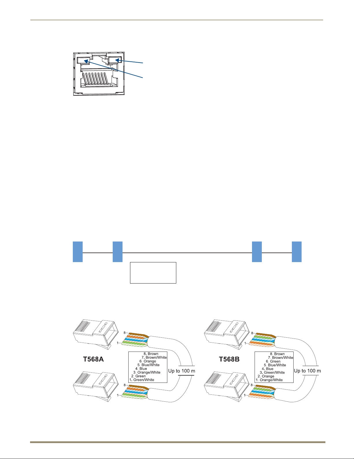
LEDs on RJ-45 Connectors
FIG. 11 RJ-45 connector LEDs
The following information applies to the LEDs on the UTP (RJ-45) transport connectors on the HDMI UTPro enclosure
and to the Input (RJ-45) connector LEDs on the Receivers.
Green:
On – link has been established
Off – no link
Yellow:
On – HDCP handshaking has occurred successfully
Blinking – no HDCP
Off – no HDMI
UTP Cable Requirements
UTP cable was designed to carry Full HD content over 100 meter (328 ft.) cables with control. For cable specifications
for the HDMI UTPro, see page 19.
In a typical installation, the cables should be stretched to their full length between the HDMI UTPro enclosure and its
Receivers. Service loops or coils of the cable will reduce the overall cable performance and should be minimized
whenever possible. The total run of a UTP cable installation may include up to two patch cables, typically as connections
to RJ-45 wall jacks (FIG. 12).
FIG. 12 UTP cable installation (only X and Z can be patch cables)
UTP Cable Pinouts
We recommend using the T568A pinout specification for termination of the UTP cable used with the UTP transport
connectors on the HDMI UTPro enclosure. The T568B pinout specification is also supported.
FIG. 13 UTP cable pinouts for T568A and T568B specifications
Page 31

Installation and Setup
31
Instruction Manual – HDMI-UTPRO-0808
HDMI matrix switching output
UTP (RJ-45) transport output
HDMI matrix switching input
HDMI transport input
HDMI-UTPRO-RX
Source device
Destination device
HDMI cable
HDMI cable
UTP cable up to 100 m (328 ft.)
HDMI patch cable
Important: Before attaching source and destination devices, we recommend reading the “Setting Up HDMI
Systems” chapter for information on concerns and considerations you should be aware of when switching
HDMI (see page 60).
FIG. 14 Cables connected for switching/transport from the first source to the first destination device
Important: UTP cable quality required in order to meet 100 meter distance should meet
ANSI/TIA/EIA 568A-5 or better specification and be rated for 250 MHz or better.
To attach cables for switching/transport:
1.
Attach an HDMI cable from the first source device to the first HDMI matrix switching input connector.
2. Attach one end of an HDMI patch cable (provided) to the first HDMI output connector.
3. Attach the other end of the HDMI patch cable to the first HDMI transport input connector.
4. Repeat Steps 1 through 3 for the remaining source devices; be sure each patch cable is connected to corresponding
numbers (2 to 2, 3 to 3, etc.). The number for the HDMI matrix switching output connector and number for the
HDMI transport input connector must match for each patch cable.
5. Attach a UTP cable to the first UTP (RJ-45) transport output connector.
6. Attach the other end of the UTP cables to the RJ-45 input connector on the first HDMI-UTPRO-RX Receiver.
For mounting information for the Receivers, see page 15.
7. Repeat Steps 5 and 6 for the remaining Receivers.
8. Connect the HDMI-UTPRO-RX Receivers to the destination devices using HDMI cables.
Page 32

Installation and Setup
32
Instruction Manual – HDMI-UTPRO-0808
IR Control (Optional)
For information on the equipment needed for IR control, see page 16.
IR Receiver
FIG. 15 IR Receiver (FG-IR03 - not included)
To connect an IR Receiver to the HDMI-UTPRO-RX Receiver:
Connect the IR03 IR Receiver (FG-IR03) cable to the IR Rx port on the Receiver.
1.
2. Run the cable and attach the IR receiver bud so that it has a clear line-of-sight with the intended remote control
device.
3. Repeat Steps 1 and 2 as necessary for additional IR remote units.
IR Emitter
FIG. 16 IR Emitter (FG-IR01 - not included)
To connect an IR Emitter to the HDMI-UTPRO-RX Receiver:
1.
Connect an IR01 IR Emitter cable (FG-IR01) to the IR Tx port on the Receiver.
2. Run the other end of the IR TX cable to the display device and locate the IR window.
3. Attach the IR Emitter bud over the device’s IR sensor by removing the cover on the reverse side of the Emitter and
sticking the bud directly over the IR window.
4. Repeat Steps 1 through 3 as necessary for additional IR remote units.
When installation of the IR Receiver and IR Emitter is complete, load the appropriate driver (see page 98) and program
the IR remote according to the product’s documentation.
Page 33

Installation and Setup
33
Instruction Manual – HDMI-UTPRO-0808
Establishing an Ethernet 10/100 Network Connection
The LAN 10/100 (RJ-45) port provides Ethernet 10/100 BaseT connectivity. The following table lists the pinouts,
signals, and paring for the port.
Ethernet Pinouts and Signals
Pin Signals Connections Pairing Color
1 TX+ 1 ------- 1 1 ------- 2 White / Orange
2 TX- 2 ------- 2 Orange
3 RX+ 3 ------- 3 3 ------- 6 White / Green
4 no connection 4 ------- 4 Blue
5 no connection 5 ------- 5 White / Blue
6 RX- 6 ------- 6 Green
7 no connection 7 ------- 7 White / Brown
8 no connection 8 ------- 8 Brown
FIG. 17 diagrams the pinouts and signals for the network RJ-45 connector and cable.
FIG. 17
Ethernet RJ-45 wiring diagram
Important: By default, the HDMI UTPro is configured for DHCP. For details, refer to the IP Settings section
on page 75.
Note: Consult the Network Administrator for correct cabling from the HDMI UTPro onto the network. For
remote connectivity, the Firewall may have to be configured to open port 1319 for remote connectivity over
UDP.
Cable Requirements for LAN Connection (or a PC’s NIC card)
An RJ-45 cable (either crossover or straight-through) is required to connect the HDMI UTPro to a LAN. The same type
of cable can also be used to connect the HDMI UTPro directly to a network card in a PC; for special instructions, see
Workaround on page 35.
NetLinx LED
The NetLinx LED is to the left of the LAN 10/100 connector. When the LED is illuminated, the NetLinx connection is
active.
Page 34

Installation and Setup
34
Instruction Manual – HDMI-UTPRO-0808
Green LED - L/A (link/Activity) Status
Yellow LED - Speed Status
NetLinx LED - Active connection
LAN LEDs
LEDs on LAN 10/100 (Ethernet) RJ-45 Connector
FIG. 18 LAN 10/100 port LEDs
The LAN 10/100 port is an Ethernet link connector, handling Ethernet 10/100 connections for 100 Mbps (megabits per
second) and 10 Mbps. (This connection is compatible with most Ethernet based LANs.)
The two small rectangular LEDs on the LAN 10/100 connector indicate the following.
Yellow Speed Status LED:
ON – Speed status is 100 Mbps
Off – Speed status is 10 Mbps
Green L/A (Link/Activity) Status LED:
ON – Link status is active (when Ethernet cables are connected and terminated correctly); blinks when
receiving Ethernet data packets
Off – Link status is not active
Note: When the connection is made, the DHCP server on the network will automatically assign an IP
address. If you power down and power back up, the DHCP server will reassign the IP address, which may or
may not be the same address it assigned before. To prevent the possibility of the IP address changing at
power up, you can change the DHCP IP address to a static IP address (see page 75).
System Setup for a LAN Connection
Important: The HDMI-UTPro uses DHCP by default.
The system setup example below illustrates an HDMI UTPro connected to a LAN. Both computers in the illustration
have access to the enclosure, as does the NetLinx Controller.
FIG. 19 HDMI UTPro connected via a LAN to two PCs and a NetLinx Controller
Tip: The directions on the following page assume that you are connecting the HDMI UTPro to an active
LAN (network) that utilizes DHCP. If not, see the “Workaround” below the instructions first.
Page 35

Installation and Setup
35
Instruction Manual – HDMI-UTPRO-0808
Zero-Config tab
IP address for HDMI UTPro
HDMI UTPro
To connect an HDMI UTPro to a LAN:
1.
Complete the installation of the HDMI UTPro including power up of the system.
2. Insert one end of the RJ-45 link cable into the LAN 10/100 port on the enclosure.
3. Connect the other end of the RJ-45 link cable to a LAN hub or switch. The network will automatically assign a
DHCP IP address (the assigned IP address can then be changed to a static IP address, see page 75). If the LAN does
not utilize DHCP, see the “Workaround” below.
4. Check the indicator LEDs for the LAN 10/100 connector (see page 34).
5. Determine the IP address by accessing Zero-Config information NetLinx Studio WebConsole (see below). Make
note of the IP address to use in the test procedure at the top of page 36. NetLinx start up takes approximately
3 minutes.
6. Complete the installation by testing the connection (see the instructions on page 36).
Note: The LAN 10/100 port can also be used to Telnet into the HDMI UTPro to determine its MAC Address
(see page 131).
Workaround for Networks that Do Not Utilize DHCP
If the network does not utilize DHCP, you must connect either to a standalone router that supports DHCP or to a PC that
is running DHCP emulation software. Once the router or PC assigns a DHCP IP address, that IP address is used to access
the WebConsole from which you must then change the DHCP IP address to the static address provided by your Network
Administrator before you connect the HDMI UTPro directly to the LAN.
Determining IP address for HDMI UTPro
The HDMI UTPro features a built-in zero-configuration networking client that allows you to determine the unit’s
IP address for the HDMI UTPro WebConsole via Bonjour for Windows
Zero-configuration (or zeroconf, also known as “Bonjour”) technology provides a general method to discover services
on a local area network. In essence, it allows you to set up a network without any configuration.
To determine the DHCP IP address that the network assigned to the HDMI UTPro in Step 3 of the previous instructions,
you can access the unit via NetLinx Studio.
NetLinx Studio version 3.0 (or higher) features a “Zero-Config” tab in the Workspace window. This tab provides
Zero-Config networking functionality within NetLinx Studio.
Note: Refer to the NetLinx Studio online help for details on using Zero-Config.
The following assumes that the WebConsole connection (LAN 10/100 port) is to the same LAN as the PC running
NetLinx Studio and the NetLinx Master for the HDMI UTPro.
®
or a similar zero-configuration client.
To determine the IP address by accessing the HDMI UTPro via Zero-Config:
In NetLinx Studio (v3.0 or higher), left-click the Zero-Config tab on the Workspace Bar to open the tab.
1.
FIG. 20 NetLinx Studio showing the Zero-Config tab and the IP address for an HDMI UTPro
Page 36

Installation and Setup
36
Instruction Manual – HDMI-UTPRO-0808
2. Right-click anywhere in the Workspace and select Refresh Zero-Config List to generate an initial listing of all
Zero-Config devices that have been detected (FIG. 20).
3. Click the plus symbol (+) to the left of the “AMX HDMI-UTPRO-0808” in the Zero-Config list to expand its
information. The HDMI UTPro’s current IP Address is listed below the device name.
To test the HDMI UTPro WebConsole connection:
Launch a browser on your PC.
1.
2. In the address bar of the browser, type the IP address and press Enter (to determine the IP address, see the previous
instructions or contact your Network Administrator).
If the WebConsole does not open, see the “WebConsole Troubleshooting” section on page 80.
For WebConsole setup details, see the “HDMI UTPro WebConsole” chapter on page 69.
Note: For additional information on Zero-Config or the WebConsole, see the “Programming Guide – NetLinx
Integrated Controllers” at www.amx.com
.
Serial Port (RJ-12)
The Serial port displays in NetLinx Studio as Port 2 of the HDMI UTPro and can be used to control an additional local
device. The port is an RJ-12 connector and may require an adapter cable to connect to the external device under control
(e.g., a Blu-Ray player). The Serial port on the HDMI UTPro has same functionality as the Serial ports on the Receivers
(which also display as Port 2 in NetLinx Studio). For cable adapter information, see page 37. Pinout information is on
page 38.
Important: This port cannot
of the Receivers (the LAN 10/100 port is used for both of these functions).
be used to control the HDMI-UTPRO-0808 or to send serial commands to any
Note: Attaching an additional external device is an optional procedure in the installation process.
FIG. 21 Device control flow diagram
Page 37

37
Instruction Manual – HDMI-UTPRO-0808
Serial port (RJ-12) connector
Default Serial Port Settings
Baud Rate 9600
Data Bits 8
Parity None
Stop Bits 1
Flow Control None
Male-Male
Adapter
Null Modem
Male-Female
Adapter
DB-9 Serial Port Pinouts
(male connector)
RS-232
Pin 2: RX signal
Pin 3: TX signal
Pin 5: GND
Null Modem
Male-Female
Adapter
Female
DB-9 Serial Port Pinouts
(female connector)
RS-232
Pin 2: RX signal
Pin 3: TX signal
Pin 5: GND
Male-Male
Adapter
DB-9 Serial Port Pinouts
(male connector)
RS-232
Pin 2: TX signal
Pin 3: RX signal
Pin 5: GND
Cable Adapter Kit for Serial port (RJ-12)
Serial Port - Default Communication Settings
The default serial settings for the Serial port are listed in the table below. The settings can be altered by sending
SEND_COMMANDs to Port 2 of the HDMI UTPro (see page 87) or the Receiver (see page 92).
FIG. 22 Serial (RJ-12) port on the HDMI UTPro
Cable Adapter Kit (FG-RS01K)
A cable adapter kit is available that contains an RS-232 serial transmit, straight-through, adapter cable and two
adapters. The kit allows you to use the adapter cable in one of three ways depending on your needs.
Serial port as DTE (data terminal equipment) interface with male connection:
Note: This cable configuration provides the equivalent of a serial port connection to a NetLinx Master.
Installation and Setup
FIG. 23 DTE interface with male connection
Serial port as DTE interface with female connection:
FIG. 24 DTE interface with female connection
Serial port as DCE (data circuit-terminating equipment) interface with male connection:
FIG. 25 DCE interface with male connection
Page 38

38
Instruction Manual – HDMI-UTPRO-0808
DB-9 Serial Port Pinouts
(female connector)
RS-232
Pin 2: TX signal
Pin 3: RX signal
Pin 5: GND
Female
HDMI UTPro
RJ-12 Port Settings
Baud Rate 9600
Data Bits 8
Parity None
Stop Bits 1
Flow Control None
Serial Port (RJ-12) Pinout
Installation and Setup
RS-01 Adapter Cable (FG-RS01)
The adapter cable can be ordered by itself for a DCE interface with female connection.
Serial port as DCE interface with female connection:
FIG. 26 DCE interface with female connection
Serial Port (RJ-12) Pinout
The following table provides the pinout configuration for the RJ-12 connector (Serial port) on the HDMI-UTPRO-0808
and also on the HDMI-UTPRO-RX Receiver.
RX RJ-12 Pinout
Function Abbreviation RJ-12 Connector
Data Set Ready DSR Pin 1
Transmit Data TD or TX or TXD Pin 2
Receive Data RD or RX or RXD Pin 3
Signal Ground GND Pin 4
Signal Ground GND Pin 5
Data Terminal Ready DTR Pin 6
To connect an external serial device:
1.
Plug the RJ-12 end of the adapter cable into the Serial port on the HDMI UTPro
(or Receiver).
2. As needed – Connect cable adapter(s) per the desired Cable Kit option on the
previous page.
3. Plug the DB-9 end of the adapter cable (or the end cable adapter) into the serial
port on the external device.
4. Check to be sure that the device’s serial port settings and serial port settings on the enclosure (see table to the right)
correspond to each other. If necessary, the default settings on the HDMI UTPro can be changed; see page 87.
Caution: To avoid system damage, follow the power-up sequence on page 40.
Page 39

Installation and Setup
39
Instruction Manual – HDMI-UTPRO-0808
Control (DB-9) port
PC: DB-9
HDMI UTPro: DB-9
Control Port (DB-9)
The Control (DB-9 port) on the HDMI UTPro is reserved for firmware upgrades to the CPU. If needed, this port can also
attach to a PC for using EDID Programmer or XNConnect software or for other traditional serial port functions
(e.g., BCS commands or third-party control*).
The Control port can be used for matrix switching control functionality as an alternative to Native NetLinx control
(which is accessed through the LAN 10/100 port and includes additional NetLinx functionality). We recommend using
only one at a time, with native NetLinx as the preferred method and the RS-232 port as a backup because commands on
the Native NetLinx connection will be accepted on a first come/first served basis (which may conflict with the BCS
commands).
* If using a third-party controller, see the controller documentation for operating instructions.
Note: Attaching an external serial controller is an optional installation procedure.
FIG. 27 Control port (DB-9 connector)
Attaching Control Port to an External Serial Controller (Optional)
An external serial controller is any device that can send and receive ASCII code over an RS-232 (null modem) serial
cable attached to the Control port on the rear of the enclosure. PCs are common serial controllers. PC requirements for
BCS (Basic Control Structure) commands are provided below; for the EDID Programmer, see page 103; and for
XNConnect, see page 111.
PC Requirements for BCS
Windows XP
Terminal emulation program (e.g., TeraTerm, PuTTY, or HyperTerminal)
Serial port
Professional® or Windows 2000®
To establish external serial control over a null modem serial cable:
1.
Use a null modem cable that matches the pin diagram in FIG. 28 for RS-232 without hardware flow control. The
AMX equipment requires pins 2, 3, and 5 only.
FIG. 28 RS-232 null modem pin diagram, no hardware flow control
Page 40

40
Instruction Manual – HDMI-UTPRO-0808
2. Plug one end of the null modem serial cable into the Control (RS-232) port on the enclosure.
Null modem serial cable
HDMI UTPro
DB-9 Port Settings
Baud Rate 9600
Data Bits 8
Parity None
Stop Bits 1
Flow Control None
FIG. 29 Attach null modem serial cable to serial port
3. Plug the other end of the serial cable into the serial port on the PC (or serial
controller/device).
4. Open the serial communication software and set the PC’s port settings to match
the HDMI UTPro default port settings (see table to the right). In addition to the
default baud rate of 9600, the HDMI UTPro enclosure supports baud rates of
19200, 38400, and 57600. The settings on the PC serial communication software
and the enclosure must correspond to each other.
Installation and Setup
Caution: To avoid system damage, follow the power-up sequence on page 40.
Applying Power and Startup
The universal power receptacle on the enclosure will accept all major international standard power sources. Standard
US power cords are provided for installations within the US. Maximum power specifications are on the power receptacle
(also listed on page 17). Always use an earth-grounded power cord / system with an HDMI UTPro. The source electrical
outlet should be installed near the HDMI UTPro, easily accessible, and properly grounded. Power should come from a
building branch circuit. We strongly recommend using a dedicated line for the system’s power. To avoid an overload,
note the power consumption rating of all the equipment connected to the circuit breaker before applying power.
Caution: We recommend attaching all power cords to a surge protector and/or an AC line conditioner.
Power-Up Sequence
The power-up sequence provided assumes that the following items have already been completed:
To apply power:
1.
2. Plug the other end of the power cord into a power strip (we recommend a 30 A power strip) that is turned off.
3. Turn on the power strip. The Power Indicator on the front of the enclosure illuminates.
Important: We recommend using a regulated power supply for the HDMI-UTPRO-RX. If you exceed the
specified voltage level for the power jack on the RX (see page 22), the warranty will be void.
4. Apply power to the HDMI-UTPRO-RX Receivers.
The sources and destinations are attached (see page 29).
External control has been attached (unless the control panel is the primary source of control).
Plug the power cord into the power receptacle on the enclosure.
Page 41

Installation and Setup
41
Instruction Manual – HDMI-UTPRO-0808
Function menu screen
Power indicator
5. Apply power to the source and destination devices.
The Power indicator on the front of the enclosure illuminates (green), indicating that the enclosure is receiving
power.
The system is ready for a test switch (see the section below).
Note: For information on checking the software version, see page 56.
Control Panel Startup
After applying power and turning on the enclosure, the LCD on the control panel illuminates and displays the Function
menu screen (FIG. 30).
The system is ready for a test switch (see the section below).
FIG. 30 Control panel startup screen
Executing a Test Switch
For the HDMI input connectors, the system stores sink information when a switch is executed and retains that
information even after the switch is disconnected. Therefore, we recommend becoming familiar with how HDMI
switching works in the HDMI UTPro by reading the “Setting Up HDMI Systems” chapter (see page 60) before
executing a test switch. Then execute the test switch to verify the system is working correctly, disconnect the test switch,
and clear the sink key cache (see page 68) before finishing the installation.
We suggest executing a test switch to verify the system is working properly before attaching all inputs and outputs.
Aside from having cables attached, the system is ready to execute switches when it ships from the factory.
The first two source and destination devices must be cabled according to the directions on page 31. After the devices are
connected, power must be applied to the enclosure and then to the devices before executing a test switch.
A test switch can be executed from any control method you plan on using with the system. Instructions for executing a
test switch with the control panel and with BCS commands are provided.
The following test switch procedure routes Input 1 to Output 2 (Level 0), disconnects all currently routed signals, and
clears the cache.
Executing a Test Switch Using the Control Panel
To execute a test switch from the control panel:
1.
Press the Function Key.
The Function menu appears.
Page 42

Installation and Setup
42
Instruction Manual – HDMI-UTPRO-0808
2. Press the Select Key to choose Change.
This places the system in Change Mode (available Input and Output Keys turn blue).
3. Press Input Key 1.
Input Key 1 flashes indicating that it is ready to switch.
(Any outputs currently connected to Input 1 will turn white.)
4. Press Output Key 2.
Output Key 2 illuminates indicating that it is ready to accept the switch.
5. Press the Take Key.
Input 1 switches to Output 2, and the keys turn blue.
6. Clear the sink key cache (use either method) –
NetLinx commands: Enter SEND_COMMAND dvUTPro,"'INSTAGATECLEAR'" (clears the cache and disconnects
all currently routed signals).
SEND_COMMAND dvUTPro,"'INSTAGATEPERSIST'" (persists the empty cache).
Enter
Or
BCS commands: Enter @et (clears the cache and disconnects all currently routed signals).
Enter ~app! (persists the empty cache). Note that the response to the @et command is @eV.
Executing a Test Switch Using BCS Commands
To enter BCS commands, the system must be attached via the Control (DB-9) port using a null modem serial cable to a
serial control device running a terminal emulation program. The settings on the PC serial communication software and
the enclosure must correspond to each other.
When using a terminal emulation program, command characters are entered and sent to the enclosure’s CPU (when the
enclosure responds, the command characters appear in the program splash screen). When all of the entered characters
appear in the splash screen, the command has been executed successfully.
The following test switch procedure routes Input 1 to Output 2 (Level 0), disconnects all currently routed signals, and
clears the cache.
To execute a test switch using BCS commands:
1.
Enter the following BCS command line: CL0I1O2T
When the “T” appears, the system has successfully executed the command. If any other characters appear, the
command was not successful. Verify that the source signal is present (visible and/or audible) at the destination.
2. Enter @et (disconnects all currently routed signals and clears the sink key cache). Note that the response to the
@et command is @eV.
3. Enter ~app! (persists the empty sink key cache).
For a complete list of BCS commands and responses, see the Instruction Manual – BCS Basic Control Structure
Protocol at www.amx.com.
Page 43

Installation and Setup
43
Instruction Manual – HDMI-UTPRO-0808
Installation Troubleshooting
If the test switch did not execute correctly:
Check the power indicator on the front of the enclosure.
If it is not illuminated, check the power cords.
Verify the status of the test switch.
If using the control panel, press the Function Key, locate Status by scrolling with the Control Dial, press the
Select Key, and press Output Key 2.
If Input Key 1 illuminates, the system established a connection between the specified input and output
connector within the enclosure.
If using SEND_COMMANDs, enter SEND_COMMAND dvUTPro,"'?C2'"
If C2-I1 appears, the test switch is routed.
If the status returns as routed correctly, the system established a connection between the specified input and
output connector within the enclosure.
If using BCS commands, enter SL0O2T.
If SL0O2T(1) appears, the test switch is routed.
If the status returns as routed correctly, the system established a connection between the specified input and
output connector within the enclosure.
Check all link and signal connections on the rear of the enclosure to make sure everything is physically set up
correctly.
Check all power switches on the source and destination devices to make sure they are all turned on.
Check all signal connections on the source and destination devices to make sure everything is physically set
up correctly.
Isolate source and destination equipment and cable problems by patching around the router using cable
adapters to check the overall signal path.
Attempt the switch again.
If the switch still does not work, contact technical support (see below).
Technical Support
If this Instruction Manual has not satisfactorily answered your questions regarding the HDMI-UTPRO-0808, please
contact your AMX representative or technical support. Have the system’s serial number ready. The system’s serial
number is normally located in two places on the enclosure: on the left rear and on the left side near the power receptacle.
We recommend recording your system’s serial number in an easily accessible location.
AMX Contact Information
3000 Research Drive, Richardson, TX 75082
800.222.0193
469.624.8000
Fax 469.624.7153
Technical Support 800.932.6993
www.amx.com
Page 44
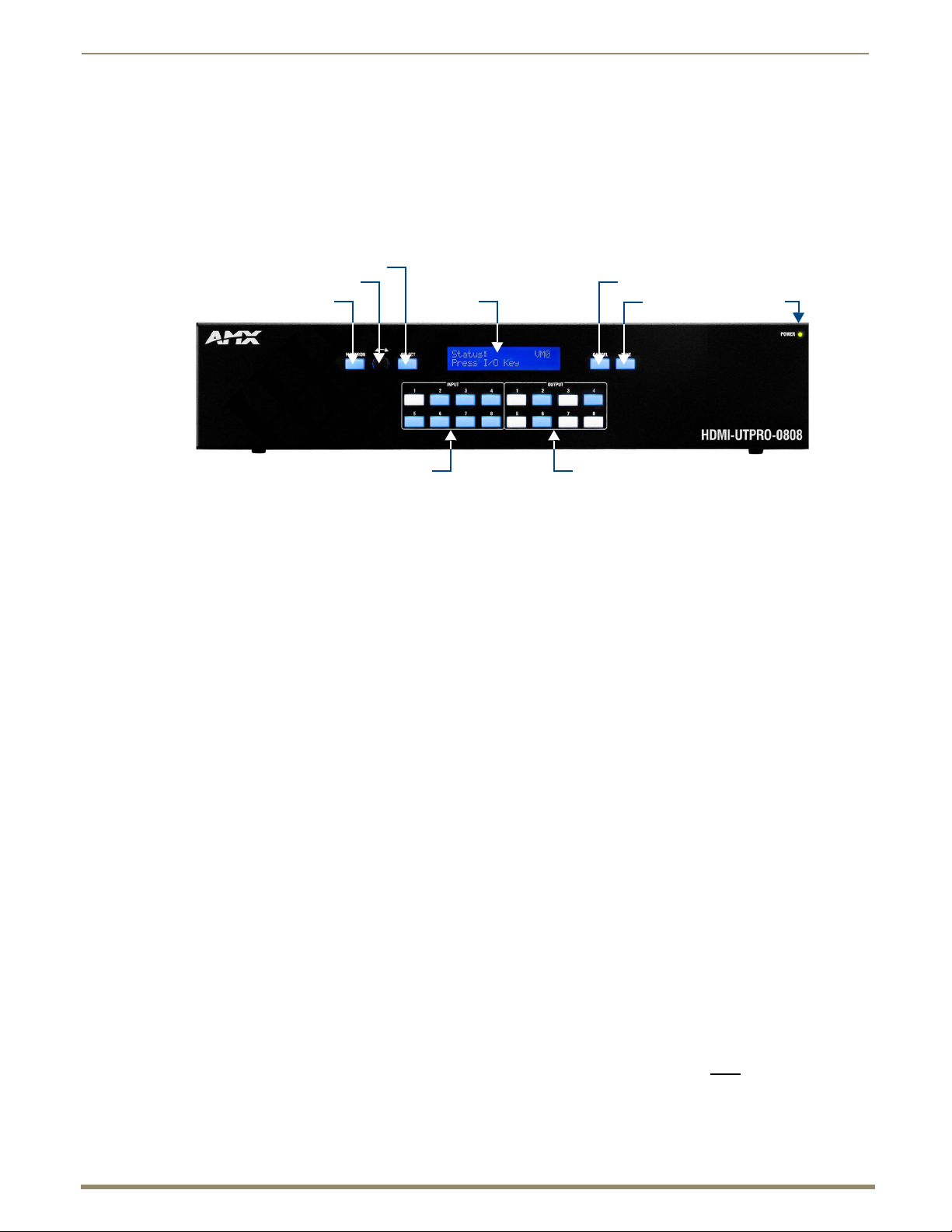
44
Instruction Manual – HDMI-UTPRO-0808
Operating the Control Panel
Function Key
Control Dial
Select Key
LCD
Cancel Key
Tak e Ke y
Power LED
Input Keys 1-8
Output Keys 1-8
Control Panel Overview
This section describes the components and features on the control panel on the front of the enclosure of the
HDMI UTPro.
FIG. 31 HDMI UTPro - control panel components
The HDMI UTPro control panel features an LCD, a Function Key, a Control Dial, a Select Key, a Cancel Key, a Take
Key, Input and Output Keys, and a Power Indicator.
Operating the Control Panel
The Control Dial and Select Key work together for scrolling through the menus displayed on the LCD to place the
system into various modes (the types of operations, e.g., Change Mode) or to access lists for control operations. Once in
the desired mode, use the Input and Output Keys to select values and the Take Key to execute the operations (some
modes require using the Control Dial and Select Key to select values).
Function Key
The Function Key accesses the Function menu on the LCD.
As the Control Dial is turned, this menu displays the various command options, e.g., Status, Disconnect, etc. The
Function Key can be pressed at anytime to return the display to the Function menu.
Control Dial
The Control Dial scrolls through menu options and adjusts values.
The Control Dial is used in conjunction with the Select Key to choose commands and values on the LCD.
Select Key
The Select Key enters a selection. In addition, the Select Key can be used to execute global presets; however, the Select
Key cannot execute or disconnect switches. Pressing the Take Key executes or disconnects switches.
LCD (Function Menu)
The LCD displays the Function Menu. For an overview of menu options, see page 46.
Cancel Key
Pressing the Cancel Key clears an incomplete operation and returns the display to the beginning of a submenu or list.
The Cancel Key cannot undo a completed operation, i.e., an operation followed by the pressing of the Take Key.
Important: If the Cancel Key flashes, an error has occurred; a flashing Cancel Key must be pressed before
continuing.
Page 45

Operating the Control Panel
45
Instruction Manual – HDMI-UTPRO-0808
Selected key flashing white
Selected keys
Available keys
illuminated white
illuminated blue
Take Key
The Take Key functions much like the Enter Key on a computer keyboard. Pressing the Take Key instructs the system to
execute or disconnect a switch. Prior to pressing the Take Key, the individual operation components are selected by
pressing the appropriate keys.
Input Keys (1-8) and Output Keys (1-8)
The Input and Output Keys correspond to the input and output connections on the rear of the enclosure. These keys are
used to select (or deselect) the inputs and outputs for routing source signals to destination devices as well as for status
operations. Input Keys are also used for locking and unlocking the control panel. When an Input or Output Key is
pressed, the channel name (e.g., O_Ch:0003 for Output 3) displays on the LCD. Hold the key down to display the name
longer.
Note: Custom channel names can be created in XNConnect (see page 113).
The Input and Output Keys illuminate depending on the mode (the type of operation) the HDMI UTPro is in:
Blue key – indicates that it can be selected as part of the current operation.
White or flashing white key – indicates that it has been selected and that further action is required to
complete the operation. A white key can also indicate routing status. White keys can be deselected.
When a key is flashing white, it cannot be deselected and does not display label information on the
LCD when pressed (to clear the operation, press the Cancel Key).
Non-illuminated key – is not available for the current operation.
Key State Example
FIG. 32 Example of key states during Change Mode
In the Key State example in FIG. 32, Input 3 is flashing white, indicating that it was selected first. Outputs 3, 6, and 7 are
illuminated white, indicating that they have also been selected (and can be deselected). The switch from Input 3 to
Outputs 3, 6, and 7 will be executed when the Take Key is pressed.
Power LED
The green Power LED illuminates when the HDMI UTPro is receiving power.
Page 46

Operating the Control Panel
46
Instruction Manual – HDMI-UTPRO-0808
Function Menu displayed Use the Control Dial to
scroll through the options
in the Function Menu
Use the Select Key to
on LCD screenselect options in the
Function Menu
Adjust Audio does not apply to the operation
of the HDMI UTPro
Local presets must be created in XNConnect
before this option appears
Function Menu Overview and Options
The Function Menu is displayed on the control panel LCD screen and provides access to various control and setup
options for the HDMI UTPro (FIG. 33).
FIG. 33 Function Menu displayed on the control panel LCD screen
The modes that apply to the HDMI UTPro are Change, Disconnect, Status , Lock, and Global Preset. While in a mode,
the same type of operations can be performed, e.g., when in Status Mode you can select various inputs to check the status
on without having to repeatedly put the control panel into Status Mode.
This section provides an overview of the menus and modes. Detailed information and instructions on the individual
modes are provided in the remainder of the chapter.
Use the Control Dial and Select Key to navigate the Function menu, submenus, and lists. The menus are loop menus
(each menu returns to the first item after you scroll past the last item).
Function Menu Options
The Function menu (FIG. 34) and its submenus access the different modes and lists used to control the
system.
FIG. 34 Function menu options
Page 47

Operating the Control Panel
47
Instruction Manual – HDMI-UTPRO-0808
The Function menu and its submenus access the following modes and lists:
Function Menu
Change Selecting Change places the system in Change Mode.
• The control panel must be in Change Mode to execute switches.
• While in Change Mode, select the Input and Output(s) Keys followed by the Take Key to execute
switches (see page 48).
Virtual Matrix Selecting Virtual Matrix accesses the VMs that are defined for the system.
• The list contains 0:All and 1:Video.
• The setting does not need to be changed as the system functions the same for either VM. The
exception is if you create VMs to manage control of sources with limited sink support (see
page 119).
Status Selecting Status places the system in Status Mode.
• While in Status Mode, signal status can be verified to confirm correct routing or routing to multiple
outputs without risk of accidentally executing a switch (see page 51).
Disconnect Selecting Disconnect places the system in Disconnect Mode.
• While in Disconnect Mode, select the Input or Output Key(s) followed by the Take Key to
disconnect switches (see page 50).
• While in Disconnect Mode, the control panel does not indicate the current routing of selected inputs
or outputs.
Setup Options Selecting Setup Options accesses this submenu’s option for checking the Software Version (see
Lock Panel Selecting Lock Panel places the panel in Lock Mode at which time the password is entered to lock the
Adjust Audio This submenu and the options under Adjust Audio do not
Global Preset Selecting Global Preset accesses this submenu’s options Execute Global Presets and Define
Local Preset Selecting Local Preset accesses local presets that can be executed (see page 115).
page 56).
• Two submenu options, Default VM (Virtual Matrix) and Reload Config, do not normally apply
unless the configuration file has been modified (see page 110 and page 119).
panel.
• Locking the control panel limits access which can prevent accidental switches (see page 55).
apply to the HDMI UTPro.
Global Presets (see page 51).
Working With the Function Menu
To choose a mode, submenu, or list – Press the Function Key to access the Function menu.
Use the Control Dial and Select Key to choose the desired mode, submenu, or list.
To select inputs or outputs – Press the corresponding Input or Output Key.
Selected keys will change color or flash, depending on the routing state (see page 45).
To select values for fields (such as a global preset value) – Use the Control Dial and Select Key.
To execute a command – Press the Take Key.
Executing Switches (Change Mode)
A switch is an active connection between an input (source) device and one or more output (destination) devices. The
signals routed in a switching operation are individual signals or groups of individual signals coming through the
connectors on the rear of an enclosure. Executing a preset is a quick way to execute multiple switches at a time. For
information on local presets, see page 54; for information on global presets, see page 51.
Note: The number of the virtual matrix (default VM 0) that operations are currently being executed on is
displayed in the upper-right corner of the display. The HDMI UTPro functions the same for its two VMs, VM 0
and VM 1.
You can execute switches from the control panel using the steps on the following page or by executing a global preset
(see page 51).
When an Input or Output Key is pressed, the channel name displays on the LCD (e.g., O_Ch:0003 for Output 3). Hold
the key down to display the name longer.
Page 48

Operating the Control Panel
48
Instruction Manual – HDMI-UTPRO-0808
Note: When you put the panel in Change Mode, available keys will be blue and any unavailable ones will not
be illuminated. The first blue key selected flashes white and the next key(s) selected turns white. You can
toggle the non-flashing white keys between the selected (white) and deselected (blue) state before pressing
the Take Key. For more information, see page 45.
In an execute switch command either an input or an output can be selected first. To switch to multiple outputs, the Input
Key must be selected first. With the control panel you can select and deselect Input and Output Keys to modify the
switch as long as the keys are not flashing. Once satisfied with the switch selections, press the Take Key to execute it.
For new installations, we recommend that before attaching all inputs and outputs, you execute a test switch routing
Input 1 to Output 2 (the example used in the instructions below).
Note: You can return to the Function menu at any time by pressing the Function Key.
To execute a switch:
Press the Function Key.
1.
The Function menu appears.
2. Press the Select Key to choose Change.
This places the system in Change Mode (available Input and Output Keys turn blue).
3. Press Input Key 1.
Input Key 1 flashes indicating that it is ready to switch.
(Any outputs currently connected to Input 1 will turn white.)
4. Press Output Key 2.
Output Key 2 illuminates indicating that it is ready to accept the switch.
5. Press the Take Key.
Input 1 switches to Output 2, and the keys turn blue.
6. Execute additional switches.
Or
Press the Function Key to return to the Function menu.
Note: The panel remains in Change Mode until the Function Key is pressed.
Page 49

Operating the Control Panel
49
Instruction Manual – HDMI-UTPRO-0808
VM used for all operations
Changing the Virtual Matrix
Selecting Virtual Matrix accesses the VMs that are defined for the HDMI UTPro.
The list contains 0:All and 1:Video (unless custom VMs have been created in XNConnect).
The setting does not need to be changed as the system functions the same for either VM.
Note: Virtual matrices are defined in XNConnect and stored in the system’s configuration file.
If you use VMs to limit control of sources with limited sink support, the VMs may need to be changed when you are
switching different inputs (for information on creating VMs for this purpose, see page 119).
Changing the virtual matrix does not change the default virtual matrix. The system will revert to switching on the default
virtual matrix when the power is cycled. For information on changing the default virtual matrix, see page 57.
The example below assumes additional VMs have been created and provides instructions for changing from routing
signals on VM 0 to routing on VM 2, a hypothetical VM labeled “Custom.”
To change the virtual matrix:
Press the Function Key.
1.
The Function menu appears.
2. Locate Virtual Matrix by scrolling with the Control Dial.
3. Press the Select Key.
The V.Matrix list appears.
4. Scroll to 2:Custom.
5. Press the Select Key to enter your selection.
The display returns to the top of the V.Matrix submenu.
VM 2 becomes the new virtual matrix used for all operations.
6. Press the Function Key to return to the Function menu.
The HDMI UTPro is ready to make changes on VM 2.
The HDMI UTPro will remain on VM 2 for all operations until the virtual matrix is changed or power is cycled
(to set the virtual matrix as the default, see page 57).
Page 50

Operating the Control Panel
50
Instruction Manual – HDMI-UTPRO-0808
Disconnecting Switches (Disconnect Mode)
Disconnecting a switch deactivates the connection between an input (source) and one or more output (destination)
devices. Disconnecting an input disconnects all outputs currently receiving that source signal. An output can only be
connected to one input; therefore, disconnecting an output will only disconnect the connection between the output and
the input that is routed to it.
You can disconnect a switch by selecting either inputs or outputs from the control panel. Inputs and outputs can be
selected in the same disconnect command.
Although switches can be disconnected when the panel is in Change Mode, the advantage of using the Disconnect Mode
is that it can be used to quickly disconnect multiple outputs receiving a signal from the same input (by disconnecting the
input) or from different inputs (by disconnecting the outputs).
Note: When you put the panel in Disconnect Mode, available keys will be blue and any unavailable ones will
not be illuminated. When you select a blue key, it turns white. You can toggle the keys between the selected
(white) and deselected (blue) state before pressing the Take Key. For more information, see page 45.
Once the control panel is in Disconnect Mode, inputs and outputs can be selected and deselected by pressing the
corresponding Input and Output Keys. The disconnect command is not executed until the Take Key is pressed.
While in Disconnect Mode, the control panel will not show current routing for the inputs and outputs that are selected.
Caution: Disconnecting an input disconnects all outputs receiving that source signal even if a specific
output(s) is selected at the same time.
Note: You can return to the Function menu at any time by pressing the Function Key.
To disconnect inputs and outputs:
This example disconnects Inputs 1 and 3 and all outputs connected to them as well as Output 9.
1. Press the Function Key.
The Function menu appears.
2. Locate Disconnect by scrolling with the Control Dial.
3. Press the Select Key.
The system is in Disconnect Mode (all the available Input and Output Keys turn blue).
4. Press Input Keys 1 and 3 and Output Key 9.
The keys turn white indicating that they are selected.
5. Press the Take Key.
Inputs 1 and 3 (and all outputs connected to them) and Output 9 are disconnected as soon as the Take Key is
pressed, and the keys turn blue.
6. Execute additional disconnects.
Or
Press the Function Key to return to the Function menu.
Page 51

Operating the Control Panel
51
Instruction Manual – HDMI-UTPRO-0808
Verifying Signal Status (Status Mode)
Signal status can be verified to confirm that a switch has executed properly or to confirm correct routing to multiple
outputs (destinations). Input status and output status both function on the control panel. An output can only be connected
to one input (source); therefore, verifying the status of an output will illuminate only the one input it is currently
connected to. Verifying an input will illuminate all outputs currently receiving the input’s signal.
The advantage of using Status Mode (instead of Change Mode, which also indicates routing) is that status is verified
without the risk of inadvertently executing unwanted switches.
Once the control panel is in Status Mode, inputs and outputs can be selected by pressing the corresponding Input and
Output Keys without changing the routing state. The control panel stays in Status Mode until the Function Key is
pressed.
Note: You can return to the Function menu at any time by pressing the Function Key.
To verify the status of a signal:
1.
Press the Function Key.
The Function menu appears.
2. Locate Status by scrolling with the Control Dial.
3. Press the Select Key. The system is in Status Mode (all available Input and Output Keys turn blue).
4. Press the Input Key that corresponds to the input you want to check.
The selected Input Key turns white, and any Output Keys receiving the input signal also turn white.
Or
Press the Output Key that corresponds to the output you want to check.
The selected Output Key turns white, and any Input Key routed to it also turns white.
5. Select another signal to verify.
Or
Press the Function Key to return to the Function menu.
Defining and Executing Global Presets (Global Preset Mode)
A global preset is a snapshot of an entire system’s state which enables that system state to be replicated at a later time.
The system state includes all current signal routings (regardless of the number of virtual matrices involved). Before
defining a Global Preset, route the system to the desired state. A global preset number is assigned to a system state
during runtime using the control panel (or BCS commands) and is stored in the switcher’s non-volatile memory. That
system state can then be restored at any time by selecting the assigned global preset number.
The HDMI UTPro can support up to 16 global presets.
AMX strongly recommends keeping track of the number used and the system’s routing state for each global preset. I
f another system state is assigned a previously used number, the former state will be automatically overwritten.
Important: Wait approximately ten seconds for the system to permanently store the global preset setting
before performing another operation.
Page 52

Operating the Control Panel
52
Instruction Manual – HDMI-UTPRO-0808
To define a global preset:
This example defines Global Preset 3, and the example on the next page executes Global Preset 3.
1. Route the system to the desired state.
2. Press the Function Key.
The Function menu appears.
3. Locate Global Preset by scrolling with the Control Dial.
4. Press the Select Key.
The Global Preset submenu appears.
5. Scroll to Define Global.
6. Press the Select Key again to choose Define Global.
The Define Global list appears.
7. Scroll to Global Preset 3.
8. Press either the Select Key or the Take Key.
9. Wait approximately ten seconds for the system to store the global preset setting.
The current routing state can now be recalled as Global Preset 3, and the system returns to the Global Preset
submenu.
10. Press the Function Key to return to the Function menu.
Page 53

53
Instruction Manual – HDMI-UTPRO-0808
To execute a global preset:
1.
Press the Function Key. The Function menu appears.
2. Locate Global Preset by scrolling with the Control Dial.
3. Press the Select Key. The Global Preset submenu appears.
4. Press the Select Key again to choose Execute Global.
The Execute Global Preset list appears.
Operating the Control Panel
5. Scroll to Global Preset 3.
6. Press either the Select Key or the Take Key.
Global Preset 3 is executed, and the system returns to the Global Preset submenu.
7. Press the Function Key to return to the Function menu.
Note: Status is not invalidated by global presets.
Page 54

Operating the Control Panel
54
Instruction Manual – HDMI-UTPRO-0808
Executing Local Presets (Local Preset Mode)
A local preset is a predetermined set of switches on a particular virtual matrix that are routed simultaneously. They are
stored in each enclosure’s configuration file and can be executed at anytime. “Local Preset” will not appear as a submenu
option in the Function menu if local presets have not already been defined. In addition, they will not appear if the system
is on a virtual matrix that does not have local presets.
Local presets are not programmed (defined) at the factory. To program them, use XNConnect (see page 115) or contact
your AMX representative (for contact information, see page 43). Once the local presets have been defined as part of the
configuration file, the new file must be loaded to the system’s CPU and reloaded to the control panel (see page 58).
Make sure the control panel is on the virtual matrix where the local preset resides. If no local presets have been defined
for the selected VM, the Local Preset submenu option will not be available on the Function menu.
Note: Executing a local preset does not change any system routings that are not part of the preset.
The example below executes Local Preset 3 on VM 0.
To execute a local preset:
Press the Function key.
1.
The Function menu appears.
2. Locate Local Preset by scrolling with the Control Dial.
3. Press the Select Key.
The Local Preset list appears.
4. Scroll to 3:Training Rm 6.
5. Press either the Select Key or the Take Key.
Local Preset 3 is executed.
6. Press the Function Key to return to the Function menu.
Or
Execute another local preset.
Page 55

Operating the Control Panel
55
Instruction Manual – HDMI-UTPRO-0808
Locking and Unlocking (Lock Mode)
Locking the panel prohibits access to the system and can prevent accidental switching. The control panel can be locked
by entering a sequence of keys. The factory default password is the first five keys in the top row (Inputs 1, 2, 3, 4 and
Output 1). The password can only be changed by using XNConnect (see page 114).
Note: Locking the control panel only locks out operations from the front panel keys. While the control panel is
locked, SEND_COMMANDs and BCS commands are still fully functional through their normal ports. Neither
protocol has commands for locking or unlocking the control panel.
The panel remains locked if the power is cycled.
Locking the Control Panel
The following example uses the default password of “1 2 3 4 1” entered using the first five keys in the top row (Inputs 1,
2, 3, 4 and Output 1).
If you enter the wrong password while attempting to lock the control panel, an invalid password message appears and the
Cancel Key flashes. Press the Cancel Key to clear the error and then enter the correct password.
Note: For security purposes, the Input Keys do not turn white when pressed while locking and unlocking the
panel.
To lock the control panel:
Press the Function Key.
1.
The Function menu appears.
2. Locate Lock Panel by scrolling with the Control Dial.
3. Press the Select Key.
The system is in Lock Mode.
4. In the following order, press Input Keys 1, 2, 3, 4 and Output Key 1 (default password).
The panel is locked, and all Input and Output Keys turn off.
Page 56

Operating the Control Panel
56
Instruction Manual – HDMI-UTPRO-0808
Unlocking the Control Panel
When the panel is locked and you press any key, the Unlock Panel screen appears and you have ten (10) seconds to enter
the password, or the control panel remains locked. If you wait longer than 10 seconds, press any key again before
entering the password.
If you enter the wrong password while attempting to unlock the control panel, an invalid password message appears and
the Cancel Key flashes. Press the Cancel Key to clear the error and then enter the correct password.
The following example uses the default password of “1 2 3 4 1” entered using the first five keys in the top row (Inputs 1,
2, 3, 4 and Output 1).
To unlock the control panel:
1.
Press any key. The Unlock Panel screen appears, and the Input and Output Keys turn blue.
Important: You must enter the password within ten (10) seconds.
2. In the following order, press Input Keys 1, 2, 3, 4 and Output Key 1 (default password).
The panel unlocks and returns to the Function menu.
Setup Options
The following options are available under the Setup Options submenu:
Software Version – to display software version information for the control panel
Default VM – to change the factory default virtual matrix
Reload Config – to load local presets information to the control panel after they are created in XNConnect
Note: The submenu options Default VM and Reload Config do not normally apply to the HDMI UTPro unless
the configuration file has been modified (see page 110 and page 119).
Checking the Software Version (Software Version Screen)
The Software Version screen provides the following information:
Driver – control panel’s firmware version
Built – date the control panel’s software was built
Host – software version of the initial operating system (IOS) for the control panel
XNet ID – control panel’s XNet device number
FP Link baud 115200 – indicates a front control panel and the baud rate
To check the software version information for the control panel:
1.
Press the Function Key.
The Function menu appears.
2. Locate Setup Options by scrolling with the Control Dial.
Page 57

Operating the Control Panel
57
Instruction Manual – HDMI-UTPRO-0808
Version number
3. Press the Select Key.
The Setup Options submenu appears.
4. Press the Select Key again to choose Software Version.
The Software Version screen appears.
5. Scroll to see additional Software Version information.
6. Press the Cancel Key to return to the Setup Options submenu.
Or
Press the Function Key to return to the Function menu.
Default Virtual Matrix
The factory default virtual matrix for the HDMI UTPro is All. It is not necessary to to change the default (the two factory
VMs switch identically), unless you have created VMs for control purposes to manage source devices with limited sinks
(see page 119).
When you choose a new default virtual matrix, the system will revert to that virtual matrix each time the system is
powered up even if you changed the virtual matrix using the V. Matrix list during normal operation. The power must be
cycled before the default virtual matrix changes are implemented. If you want to immediately switch on the default
matrix, either change the current virtual matrix (see page 49) or cycle the power.
The following example assumes additional VMs have been created and it provides instructions for changing the default
virtual matrix from “All” to a hypothetical VM labeled “Custom.” (The V.Matrix list contains all VMs that are currently
available on the system.)
To change the default virtual matrix:
1.
Press the Function Key.
The Function menu appears.
2. Locate Setup Options by scrolling with the Control Dial.
3. Press the Select Key.
The Setup Options submenu appears.
4. Scroll to Default VM.
5. Press the Select Key.
The Default VM list appears.
Page 58

Operating the Control Panel
58
Instruction Manual – HDMI-UTPRO-0808
6. Scroll to 2:Custom.
7. Press the Select Key
The display returns to the top of the Setup Options submenu.
8. Cycle power to implement VM 2 as the default virtual matrix.
Or
Change the virtual matrix (see page 49) to immediately perform operations on the new default virtual matrix
without cycling power. (The next time power is cycled, VM 2 will be implemented as the default virtual matrix.)
Reloading the Configuration File
The configuration file contains system information that is loaded to the CPU in the matrix switcher. The Control Panel
automatically references this information during all of the control operations.
When changes are made to the configuration file in XNConnect (e.g., customizing channel names or creating presets),
the modified configuration file must be loaded to the system’s CPU using one of the Configure menu options (see the
XNConnect Help file).
If the configuration file was loaded to the system’s CPU using any of the following options, the control panel will need
to reload the file.
Configure / Configure Special – Virtual Matrix / any of the three choices
Configure / Configure Special – Hardware / Configure All Device Names
Configure Special (from the enclosure’s shortcut menu) / Configure Virtual Matrices
The file can be reloaded by following the directions below or by right-clicking the CP-15 icon (this is the icon used for
the HDMI UTPro control panel) in XNConnect and selecting Configure from the shortcut menu.
To reload the configuration file:
Press the Function Key. The Function menu appears.
1.
2. Locate Setup Options by scrolling with the Control Dial.
3. Press the Select Key.
The Setup Options submenu appears.
4. Scroll to Reload Config.
5. Press the Select Key.
The display returns to the top of the Setup Options submenu, and the configuration file reloads from the CPU to the
control panel. (Depending on the file size, reloading may take a few moments.)
Page 59

Operating the Control Panel
59
Instruction Manual – HDMI-UTPRO-0808
System Error Codes on Control Panel LCD
If you are experiencing problems with your HDMI UTPro, you can enable error code reporting on the control panel’s
LCD (see below). If the system has an error code associated with the problem, the error code will then display on the
LCD.
The most common error code likely to appear on the LCD is listed in the table.
Most Common System Error Code
Error Code Name Meaning Troubleshooting Strategies
EFF8002 Enclosure
time out error
Other error codes rarely appear. Note that the error code in the table starts with an E. Error codes can also start with a W
(warning), an A (alarm, requires immediate attention), or an I (information). If an error code other than EFF8002
appears, note the specific number and contact technical support (see page 43).
The following instructions are for using a terminal emulation program on a PC (to establish connection, see page 39).
To enable error code reporting:
Enter $ERR=1!
1.
The system responds with V
Note: If the power is cycled, you will need to enable error code reporting again.
The operation was not completed
before the timer expired.
• Re-send the command.
• Check the power indicators.
To turn off error code reporting:
Enter $ERR=0!
1.
Error Codes – General Troubleshooting
Error codes can appear either on the control panel or in a terminal emulation program, such as TeraTerm, PuTTY, or
HyperTerminal.
When you are using the control panel, one of the most common troubleshooting strategies is to re-send the command to
see if the error was simply a time out error.
When you are using BCS (Basic Control Structure) commands, one common troubleshooting strategy is to enter the
command again. Often the command has simply been entered incorrectly (e.g., omitting an output in a Change
command).
Page 60

60
Instruction Manual – HDMI-UTPRO-0808
Setting Up HDMI Systems
Applicability Notice
This chapter pertains to using the HDMI UTPro’s HDMI matrix switching connectors and the HDMI and UTP transport
connectors in conjunction with HDMI-UTPRO-RX Receivers for setting up an HDMI system.
The HDMI connectors are designed to route high-resolution HDMI or DVI signals with or without HDCP
(High-bandwidth Digital Content Protection). DVI signals must be, single-link DVI signals and are connected only with
the use of a cable adapter. Destination devices with either DVI-I or single-link DVI-D connectors are supported.
The HDMI connectors are HDMI and HDCP 1.3 compatible. The connectors feature AMX HDCP InstaGate®
Technology* for low-latency switching of HDCP protected content and supports computer video up to 1920x1200 and
HDTV up to 1080p. The connectors also support embedded audio both linear PCM (stereo audio) and non-linear PCM
(Dolby 5.1 and DTS 5.1).
The connectors are pre-loaded with the most common EDID settings to ensure proper functionality with source devices.
The EDID Programmer (see page 101) allows specific display EDID settings to be custom loaded on each input if
desired and is available at www.amx.com.
* InstaGate
latency and interruptions are typically experienced when High-Bandwidth Digital Content Protection (HDCP)
authenticates HDMI or DVI source and destination devices. InstaGate
pre-authorizing connected source and destination devices to satisfy HDCP authentication.
®
Technology significantly reduces the HDCP latency and interruptions on all displays in a system. HDCP
Setting Up HDMI Systems
®
Technology effectively “opens the gate” by
System Overview
The HDMI UTPro provides true matrix switching for complete distribution of high resolution digital video and
embedded audio (cannot breakaway the audio) from 8 sources to any or all of 8 destinations. Full HDMI support allows
1080p protected entertainment content to be switched freely, while high resolution capabilities (1920x1200) provide the
advantage of being able to use this solution to switch high resolution computer images or a combination of both.
The HDCP standard was established to prevent the unauthorized transfer of protected audiovisual content between
devices.
The HDMI UTPro routes HDCP (content-protected) and non-HDCP digital audiovisual signals. If HDCP is applied, the
transmitted video is encrypted. The HDMI matrix switching input connectors act as HDCP receivers (RXs), and the
output connectors act as HDCP transmitters (TXs). If the content is protected (HDCP), the HDMI UTPro acts as an
HDCP repeater, allowing the source device to authenticate each destination device (and repeater) that it is routed to.
Once the authentication is complete, the encrypted content begins to display on the destinations.
Note: The HDMI UTPro does not support CEC.
HDMI UTPro System Conditions
HDCP is used only when the source content is copyright protected. Unprotected content is not affected and
may be routed as desired.
If a source device enforces HDCP compliance, only those destination devices which are HDCP compliant
(as judged so by the source device) will be capable of displaying the source’s HDCP protected content.
Each HDMI matrix switching input on the HDMI UTPro supports a maximum of 16 downstream devices,
which are referred to as sinks (destination devices and repeaters).
Normally, all devices used in an HDMI system are HDCP compliant. Each HDCP capable device model has a unique set
of confidential keys (used to encrypt and decrypt the data).
The content protection process for the point-to-point connection between the upstream transmitter on the source device
and an HDMI matrix switching input connector (RX) and on through the HDMI output connector (TX) to the destination
device* includes five steps.
* This applies whether the HDMI matrix switching output is cabled directly to the destination device or cabled through
the HDMI transport inputs, UTP transport outputs, and the HDMI-UTPRO-RX Receivers before reaching the
destination device.
Page 61

Setting Up HDMI Systems
61
Instruction Manual – HDMI-UTPRO-0808
Five Steps in Content Protection Process
1.
The HDMI UTPro uses an authentication protocol to verify that the display device is licensed to receive the content.
2. The transmitter on the source device uses authentication protocol to verify that the HDMI UTPro matrix switching
input (RX) and any routed downstream sinks are licensed to receive the content.
3. The content is encrypted and transmitted.
4. The source device’s transmitter periodically verifies that the HDMI UTPro input is still synchronized and capable
of decrypting the protected content.
5. The HDMI UTPro periodically verifies that the display device(s) is still synced and capable of decrypting the
protected content.
Note: If the source does not support HDCP, the display device does not need to support HDCP. The
unencrypted content from the source is simply routed through the output(s) to the display device(s).
Unsuccessful Transmission in System
Note: Be sure the destination devices support the resolution of the source device.
If an HDMI-UTPRO-0808 system does not successfully transmit the protected content to any of the routed sinks, it may
indicate one of the following conditions:
Invalid key – The HDMI-UTPRO-0808 enclosure’s output connector detected an invalid authentication key
on the destination device.
Non-compliant device – The sink device is not HDCP compliant or has had its authentication key revoked.*
Source sink support limit exceeded – The source device has been routed to more sinks (display devices and/or
repeaters) than it can support.
HDMI-UTPRO-0808 HDMI input sink support limit exceeded – The input is actively routed to more than
16 downstream sinks (display devices and/or repeaters).
* Key revocation is handled strictly by the source device. The HDMI-UTPRO-0808 does not take any action with
respect to revoked keys.
Supported Number of Sinks
HDCP source devices and the HDMI UTPro inputs each support a specific maximum number of sinks.
HDCP Source Device
Each source has a specific number of sinks (repeaters and/or destination devices) that it can support in addition to the
first downstream repeater (which may or may not be an HDMI-UTPRO-0808 enclosure). The number of sinks the
source supports downstream of the first repeater is determined by the source’s manufacturer.
HDMI-UTPRO-0808
Each input on the HDMI-UTPRO-0808 enclosure supports a maximum of 16 downstream sinks (repeaters and/or
destination devices). The HDMI-UTPRO-0808 enclosure, which functions as a repeater, may or may not be the first
repeater in the system. The HDMI-UTPRO-RX Receiver does not
Once a source is routed through the HDMI-UTPRO-0808 enclosure to a sink, that sink’s key is added to the input’s sink
key cache (list of supported sinks) and remains in the cache even if the sink is disconnected.
One Sink Too Many
Tip: We recommend keeping track of the number of sinks (repeaters and destinations) in a system to avoid
the problem of having one too many.
If you attempt to route the source to an additional sink past its limit or the HDMI UTPro input’s limit of 16 (whichever
occurs first), the protected content will not be transmitted to any of the routed sinks.
Having one sink too many can occur in two different cases (the solution for each is also different).
If a source supports less than 16 sinks downstream from the HDMI UTPro and an additional sink past the
source’s limit is added anywhere in the system, the protected content stops transmitting. Removing a repeater
between the source and the HDMI UTPro enclosure will restore transmission of protected content.
Disconnecting a sink downstream from the HDMI UTPro enclosure, will not restore the transmission of
protected content because the disconnected sink’s key is still in the input’s sink key cache. The cache needs to
be cleared and the cleared state needs to be persisted (if the cache was previously persisted) so authentication
can be completed again (for cache information, see page 68).
count as a sink.
Page 62

Setting Up HDMI Systems
62
Instruction Manual – HDMI-UTPRO-0808
HDMI-UTPRO-0808 (Repeater)
Source Device
Destination
Devices
HDMI-UTPRO-RX
HDMI-UTPRO-RX
HDMI-UTPRO-RX
Destination
Devices
HDMI-UTPRO-0808 (Repeater)
Source Device
Repeater
HDMI-UTPRO-RX
Repeater
Repeater
HDMI-UTPRO-0808 (Repeater)
Destination Device
HDMI-UTPRO-RX
Source Device
If a source could support 16 or more sinks downstream from the HDMI UTPro and a 17
th
sink is added
downstream of the HDMI UTPro, the protected content stops transmitting and the HDMI matrix switching
input automatically clears its cache. The input will authenticate each of the downstream sinks again, but when
it reaches the 17
th
sink, the protected content stops transmitting and the cache is cleared. This process will
continue indefinitely until one of the HDMI UTPro’s downstream sinks has been unplugged, bringing the
number back to 16 (the HDMI UTPro’s sink limit).
Four Examples of HDCP Source Sink Support (FIG. 35 through FIG. 38):
The next four figures illustrate system setups in which the source device supports a maximum of 3 sinks downstream of
the first repeater (R1) with varying numbers of repeaters and destinations.
FIG. 35 Example #1 – Source device supports 3 sinks (three destination devices) downstream of R1
FIG. 36 Example #2 – Source device supports 3 sinks (R2 and two destination devices) downstream of R1
FIG. 37 Example #3 – Source device supports 3 sinks (R2, R3, and one destination device) downstream of R1
Page 63

Setting Up HDMI Systems
63
Instruction Manual – HDMI-UTPRO-0808
Destination Device
Repeaters
HDMI-UTPRO-0808 (Repeater)
Source Device
HDMI-UTPRO-RX
FIG. 38 Example #4 – Source device supports 3 sinks (R2, R3, and one destination device) downstream of R1
Determining Sink Support Maximum on a Source Device
Determining how many sinks the source can support is necessary to make sure the system runs smoothly.
Note: If you already know how many sinks each source supports, go to “Initializing InstaGate
®
Technology”
on page 66 to do an initial authentication of HDMI source and destination devices.
This section is intended to help analyze the system based on the types of source devices used, so any limits imposed by
the source devices within the matrix switching system can be addressed. For example, if a source that supports a very
low number of sinks is switched to more sinks than that source can handle, the protected content will not be transmitted
to any of the routed sinks.
The easiest way to determine the sink support maximum on a source device is to reference the information from the
equipment manufacturer’s product documentation. If documentation is not available, we recommend following the
instructions below (an example is also provided on page 64).
Important: During the procedure below, keep in mind that the “failure condition” (in which HDCP
authentication fails to occur) varies by source device manufacturer and may manifest itself in one of several
ways, e.g., snow, static, a solid color, no image at all, or a flashing image (where the image changes back and
forth at a high speed from the correct image to a black screen).
As soon as a source is switched to one more output than it can support, the protected content will not be transmitted to
any of the routed sinks.
To determine sink support maximum up to 8 on a source device:
1.
Connect the source device to an input on the HDMI-UTPRO-0808 enclosure and connect destination devices to all
outputs on the 8 HDMI-UTPRO-RX Receivers.
2. Establish serial control between the HDMI-UTPRO-0808 enclosure and the PC with a null modem serial cable via
the Control port (see page 39).
3. Using your preferred method of control, send a command to make sure all outputs are disconnected from the input
for the source device.
4. On the PC, open a terminal emulation program (e.g., TeraTerm, PuTTY, or HyperTerminal) and enter @et to clear
any keys for supported sinks that may be cached within the InstaGate
®
layer. Note that the response to the @et
command is @eV.
Note: During this process, the destination device must
be connected directly to the output of the
HDMI-UTPRO-RX (which is connected to the matrix switcher) and not going through additional equipment
(e.g., a repeater).
5. Execute a switch to the first display device connected to the HDMI-UTPRO-0808 enclosure (i.e., add a sink to the
source). A delay in the display of the video image of approximately 3 to 10 seconds* can be expected due to the
source engaging the display device for the first time initialization of HDCP authentication. (It is normal for the
remaining monitors to lose and then regain content as each new output is added.)
6. Once a stable video image is seen at the destination device, continue routing the source to one additional output at a
time (i.e., add each new sink to the source one at a time) until one of the following occurs (be sure to wait for the
HDCP validation process and the resulting stable image to show each time before adding another output):
If the source fails to validate a destination device and the image is lost, the number of sinks the source
supports is equal to the total number of sinks that properly displayed the image before all video was lost.
To verify the failure is due to a source support limitation and not a revocation of the destination device’s key,
clear the cache on the input (see page 68), then route the source to the last destination device again, and verify
stable video.
All 8 outputs are validated and show content, i.e., source’s sink support maximum is 8 or more.
* Time for initial authentication can vary noticeably for different source and destination devices.
Page 64

64
Instruction Manual – HDMI-UTPRO-0808
HDMI-UTPRO-0808
R1
Source Device
Destination devices (5 sinks supported downstream of R1)
Note: Monitors are numbered
to indicate output numbers.
Example Determining Sink Support
Example of Determining Sink Support (FIG. 39):
FIG. 39 illustrates a source device that was checked and found to support only 5 sinks past R1. The check included the
following: From a clear matrix state (the cache is clear), the source device was routed to Outputs 1, 2, 3, 4, and 5 one at
a time as a stable image appeared on each destination device. When attempting to route the source device to the sixth
output, all displays lost content. Only five of the destination devices will be able to receive a signal from this source.
At this point, the limitation of the source device was noted and the cache cleared (see page 68). The remaining sources
were checked one at a time using the same method, and then the system was initialized using InstaGate
(see page 66) to route each source device to specific destination devices (up to the maximum each source supports).
Setting Up HDMI Systems
®
Technology
FIG. 39 Determining sink support
The previous process works for verifying sink support for a source device up to 8 sinks. If the process did not cover the
needs of the installation (extra repeaters, etc.), continue with the next one until full system capabilities are mapped out.
The next process works for determining if additional sinks are supported by the source device up to a maximum of
16 downstream of the HDMI UTPro.
Even though the connected source device may support more than 16 sinks, the HDMI UTPro only supports 16 sinks per
input. The HDMI UTPro will not allow the source device to route its signal to more than 16 sinks downstream of the
HDMI UTPro.
To determine sink support maximum from 8 up to 16 on a source device:
1.
If not already completed, complete the previous instructions.
2. Disconnect the first destination device from the HDMI UTPro and connect a new destination device in its place
(this increases the total number of sink devices by one). (Alternatively, attach an HDCP supported repeater to the
output, and attach the repeater to the same destination device.)
3. Repeat Step 2 for the remaining outputs until either all 8 destination devices show the image from the source or a
failure point is reached.
Page 65

Setting Up HDMI Systems
65
Instruction Manual – HDMI-UTPRO-0808
VM 2 (red)
VM 1 (orange)
VM 3 (blue)
Dealing with Sources with Limited Sink Support
For sources with limited sink support, the following system design considerations and control suggestions are provided.
System Design Considerations
If at all possible, replace the source device with one with that supports more sinks.
If a repeater is connected between the source and the HDMI UTPro and the repeater is not necessary, remove
the repeater and connect the source device directly to the HDMI matrix switching input. The HDMI UTPro
becomes the first repeater and one sink is eliminated, allowing you to add one more destination to the system.
If a repeater is connected between the HDMI UTPro and a display device and the repeater is not necessary,
remove the repeater and connect the display device directly to the UTP (RJ-45) output. This eliminates the
one sink, allowing you to add one more destination to the system.
Example of Reducing Sinks:
A reduction in sinks can be made by removing unnecessary repeaters either upstream or downstream of the HDMI
UTPro.
If a source supports five sinks downstream of the first repeater and the sinks (repeaters and destination devices) total six,
removing a repeater will reduce the number to five. In this example, the source will not transmit the protected content
until the number of sinks is reduced to five or less.
Important: If the repeater that is removed is downstream of the HDMI UTPro, you will need to clear the
input’s sink key cache and then persist the cleared state to eliminate the key(s) before routing the source to
any of the destinations; for instructions, see page 68.
Control Suggestions
Either a controller or a modified configuration file can provide a workaround for sources with limited sink support.
Program an external controller so that the source(s) can only be routed to a limited number of specific
destination devices.
Use XNConnect to create a virtual matrix (VM) that limits routing of the source(s) to a limited number of
specific destination devices.
Example Set of 3 VMs
External Controller
For control programming information for an HDMI UTPro using an external controller, see the external controller’s
documentation.
Tip: Locking the control panel after routing the desired sources can prevent accidental switching of a source
to more sinks than it supports and the resulting need to empty the cache and go through the initial
authorization process again. For locking instructions, see page 55.
XNConnect
XNConnect can be used to create virtual matrices (VMs) which limit the routing of a source to specific destinations.
Caution: Virtual matrix modifications are an advanced feature of XNConnect that should not be attempted
unless you are familiar with XNConnect and the AMX Matrix Switcher being configured.
To create new virtual matrices, we recommend contacting technical support (see page 43) to request a custom
configuration file. If you decide to create them yourself, see page 119 or the XNConnect Help file.
FIG. 40 Example of VMs created for control of sources with limited sink support
Page 66

Setting Up HDMI Systems
66
Instruction Manual – HDMI-UTPRO-0808
The virtual matrices in this example assume no repeaters are used upstream or downstream of the HDMI UTPro. This
example is also used in “Appendix D – Creating Virtual Matrices” (see page 119).
VM 1 – The sources connected to the inputs in orange (Inputs 1 through 6) each support 8 sinks and can be
routed to any or all of the outputs in orange on VM 1 (Outputs 1 through 8).
VM 2 – The source connected to the input in red (Input 7) supports only 4 sinks and can be routed to any or
all of the outputs in red on VM 2 (Outputs 1, 2, 3, and 4).
VM 3 – The source connected to the input in blue (Input 8) supports only 3 sinks and can be routed to any or
all of the outputs in blue on VM 3 (Outputs 5, 6, and 7).
Note: When an input is routed to an output that is already receiving a signal on a different VM, the previous
signal is disconnected and the new one takes its place.
Troubleshooting Audio
Before troubleshooting audio, it helps to understand how the system handles EDID information.
The HDMI UTPro reads the destination's EDID to verify that it is HDMI capable.
The source reads and adapts to the EDID on the HDMI UTPro matrix switching input connector. The factory
default EDID is set to support Dolby, DTS, and high PCM frequencies. This EDID can be modified by using
the one of the methods described under “Possible Solutions” below.
Important: The HDMI UTPro does not
which means the source does not know what the destination’s EDID is nor can the source make any
destination dependent changes.
pass the EDID information from the destination back to the source,
Audio Problems
If the destination device does not output the audio or if the audio crackles, it may indicate that the destination device
does not support all of the features in the default EDID on the HDMI UTPro. Some sources can choose what signal types
(audio and video) they are sending to a destination based on the destination’s EDID. Therefore, connecting the source
directly to the destination may work fine because the source chooses, for example, PCM rather than Dolby (since it
knows the destination cannot handle Dolby). Then when the HDMI UTPro is installed between the source and the
destination, the source reads the HDMI UTPro input’s default EDID and so it sends Dolby. But if the destination cannot
handle Dolby, the signal will not work.
Possible Solutions
One thing to try is to use the EDID Programmer to read the EDID from the destination device (see page 103) and to write
it to the HDMI UTPro matrix switching input (see page 104).
Another thing to try is to use the EDID Programmer to write an EDID to the matrix switching input connector on the
HDMI UTPro that best represents the downstream destination. Check the “EDID Library” file at www.amx.com
for EDID Library) to determine if one of the custom EDID files (which are variants of base EDIDs) meets your needs.
For additional information on custom EDID files, see page 105.
(search
Initializing InstaGate® Technology
InstaGate® Technology significantly reduces latency (time required for authentication) in the matrix switcher for HDCP
negotiations with the displays in a system. The latency is typically experienced when HDCP authenticates HDMI source
and destination devices. This technology effectively “opens the gate” by pre-authorizing the connected source and
destination devices to satisfy HDCP authentication.
After the first time a sink is validated by a source, when the source is routed to that same sink, the time required to
authenticate that sink is greatly reduced and protected content is displayed with less delay.
Note: Some destination devices have a longer lag time than others between receiving a signal and displaying
that signal. Although InstaGate
inherent lag time of a device.
®
significantly reduces latency in the matrix switcher, it cannot reduce the
Page 67

67
Instruction Manual – HDMI-UTPRO-0808
When the system is initially set up, each first time switch to an output must go through the lengthy authentication
HDMI UTPro
Serial Port Settings
Baud Rate 9600
Data Bits 8
Parity None
Stop Bits 1
Flow Control None
process. After the initial authentication, the system “remembers” the destination device and significantly reduces the
latency.
Note: If necessary, EDID Programmer software (located at www.amx.com) is available for re-programming
the HDMI connectors (see page 101).
We recommend using either of the following procedures at installation or whenever source and/or destination devices are
changed, so that the system is primed to accept all destinations (given any limitations on the number of sinks each source
supports; see page 61).
To initialize (prime) system for InstaGate® Technology with control panel or software:
Note: The following process can take up to as much as a minute and a half for each one-to-all routing
command to complete.* It is normal for the remaining monitors to lose content as each new output is added.
1. Check to be sure all source and destination devices attached to the HDMI UTPro are powered up.
2. Route each input to all of the outputs.
* Time for initial authentication can vary noticeably for different source and destination devices.
To initialize (prime) system for InstaGate® Technology using BCS commands:
1.
2. Plug one end of a null modem serial cable into the Control (RS-232) port on the enclosure. The pinout for the DB-9
3. Plug the other end of the serial cable into the serial port on the PC.
4. Open a terminal emulation program (e.g., TeraTerm, PuTTY, or HyperTerminal).
5. Select the COM port and set the settings to match the default ones in the HDMI UTPro
6. Apply power to the HDMI UTPro.
Important: As you enter each of the commands in Step 7, check to be sure all
destinations display stable video. If a destination (sink) does not support HDCP, its
display will turn solid red.
(If any of the commands fail, try routing the input to each output individually.)
7. Enter the following sequence of commands, which routes each source to all destinations.
As the process is completed, the keys for the destination devices are stored in the HDMI-UTPRO-0808 enclosure’s sink
key cache for the input.
The HDMI UTPro caches the keys and continuously sends them to the source (in a cumulative manner) even if the
source is only connected to a single output at a time. If that single input has been switched to more of the outputs than its
sink key cache will support, the source device will fail.
* Time for initial authentication can vary noticeably for different source and destination devices.
Note: For additional information on BCS commands, see the “Instruction Manual – BCS Basic Control
Structure Protocol” on the at www.amx.com.
Setting Up HDMI Systems
Or
Route each input to all of the runtime intended outputs.
Check to be sure all source and destination devices attached to the HDMI UTPro are powered up.
connector is: 5 GND to 5 GND, 2 RXD to 3 TXD, and 3 TXD to 2 RXD.
Serial Port Settings table to the right.
Click OK.
A short splash screen appears.
(Each one-to-all command can take up to as much as a minute and a half to complete.* It is normal for the
remaining monitors to lose and then regain content as each new output is added.)
CI1O*T
CI2O*T
CI3O*T
CI4O*T
CI5O*T
CI6O*T
CI7O*T
CI8O*T
Or
Route each input to all runtime intended outputs with BCS commands.
Page 68

Setting Up HDMI Systems
68
Instruction Manual – HDMI-UTPRO-0808
The HDMI Connector’s Sink Key Cache
If you need to persist the sink key cache on the HDMI UTPro matrix switching input connectors or clear persistence of
the cache, follow the instructions provided.
Important: These commands apply to the routing state of the entire system. In addition, all HDMI matrix
switching inputs in the system receive the request. These commands cannot
SEND_COMMANDs
The HDMI UTPro supports SEND_COMMANDs for saving and clearing the sink key cache on all of its HDMI matrix
switching inputs.
Command to Persist (Save) Sink Key Cache
To persist the Sink Key cache using SEND_COMMANDs:
Complete the procedure for initializing the system for InstaGate® Technology (see page 67).
1.
2. Enter SEND_COMMAND dvUTPro,"'INSTAGATEPERSIST'" (persists the cache).
Commands to Clear Persistence of the Sink Key Cache
To clear persistence of sink key cache using SEND_COMMANDs:
1.
Enter SEND_COMMAND dvUTPro,"'INSTAGATECLEAR'" (clears the cache and disconnects all currently
routed signals).
2. Enter SEND_COMMAND dvUTPro,"'INSTAGATEPERSIST'" (persists the empty cache).
be sent to specific inputs.
BCS Commands
As a backup, the HDMI UTPro also supports BCS commands for saving and clearing the sink key cache on all of its
HDMI matrix switching inputs. This procedure requires a terminal emulation program (e.g., TeraTerm, PuTTY, or
HyperTerminal).
Command to Persist (Save) Sink Key Cache
To persist the Sink Key cache using BCS commands:
1.
Complete the procedure for initializing the system for InstaGate® Technology (see page 67.)
2. Enter ~app! (persists the cache).
The HDMI UTPro will warm boot and display its boot screen.
Commands to Clear Persistence of the Sink Key Cache
To clear persistence of sink key cache using BCS:
1.
Enter @et (clears the cache and disconnects all currently routed signals).
Note that the response to the @et command is @eV.
2. Enter ~app! (persists the empty cache).
Page 69

69
Instruction Manual – HDMI-UTPRO-0808
HDMI UTPro WebConsole
Click here to log in
Hover mouse here to access
the Admin drop-down menu
Overview
HDMI UTPro has a built-in WebConsole that allows you to make various configuration settings via a web browser on
any PC that has access to the enclosure. The WebConsole consists of a series of web pages that are collectively called the
“Configuration Manager” (FIG. 41).
HDMI UTPro WebConsole
FIG. 41 Configuration Manager - IP Settings page (initial view)
Minimum Web Browser Requirements
Microsoft Internet Explorer 7.0 or higher, Firefox 3.68 or higher, or any other web browser compatible with
Note: The instructions in this chapter assume that the HDMI UTPro has established an active connection to a
LAN and is receiving power (see page 35).
Determining the IP Address of the HDMI UTPro
The HDMI UTPro features a built-in zero-configuration networking client that allows you to determine the unit’s IP
address via Bonjour or a similar zero-configuration client. Zero-configuration (or Zeroconf, also known as “Bonjour”)
technology provides a general method to discover services on a local area network. In essence, it allows you to set up a
network without any configuration.
Accessing Zero-Config Information in NetLinx Studio 3.0
NetLinx Studio version 3.0 (or higher) features a “Zero-Config” tab in the Workspace Window. This tab provides
Zero-Config networking functionality within NetLinx Studio.
The following assumes that the HDMI UTPro resides on the same LAN as the PC running NetLinx Studio and the
NetLinx Master to which the HDMI UTPro is connected.
To determine IP address by accessing the HDMI UTPro via Zero-Config in NetLinx Studio:
1.
In NetLinx Studio (v3.0 or higher), left-click the Zero-Config tab on the Workspace Bar to open the tab.
2. Right-click anywhere in the Workspace bar and select Refresh Zero-Config List to generate an initial listing of all
Zero-Config devices that have been detected (FIG. 42).
3. Click the plus symbol (+) to the left of any device in the Zero-config list to expand its information.
4. The HDMI UTPro’s current IP Address is listed below the device name.
Note: Refer to the NetLinx Studio online help for additional details on using Zero-Config
these browsers
Page 70

HDMI UTPro WebConsole
70
Instruction Manual – HDMI-UTPRO-0808
Zero-Config tab
IP address for HDMI UTPro
HDMI UTPro
FIG. 42 Zero-Config list showing network with HDMI-UTPRO-0808
Note: The serial number displays at the end of the product name in the Zero-Config tree.
Accessing the WebConsole
Caution: We strongly recommend that the WebConsole site be placed inside your network firewall and that
system security be turned on.
To access the WebConsole:
1.
From the NetLinx Studio Zero-Config tab – Double-click on “AMX-HDMI-UTPRO-0808” or right-click and
select one of the launch browser options.
The initial view is a display-only* view of the IP Settings page.
Or
In the Address Bar of your PC’s browser – Type the IP Address of the target HDMI UTPro and press Enter. The
PC must be on the same subnet (e.g., 192.168.X.X).
The initial view is a display-only* view of the IP Settings page.
FIG. 43 IP Settings page
If the IP Setting page does not open, see the “WebConsole Troubleshooting” section on page 80.
* Note that the IP Settings page is display-only, because you have not yet logged in. You must log in before making
changes to the IP Settings page and to access the other pages described in this section. To log in, click the Login button
in the upper right-hand corner.
Page 71

HDMI UTPro WebConsole
71
Instruction Manual – HDMI-UTPRO-0808
Port 1 - main device port / IR Receiver
Port 2 - Serial (RS-232) port
Port 3 - IR device port
HDMI-UTPRO-RX
Port 1 - control and switching
Port 2 - output control strings to a
Port 3 - reserved for future use
HDMI UTPro
connected device
Admin Menu
Several configuration pages are included in the Configuration Manager, all of which are accessed via the Admin
drop-down menu (FIG. 44).
FIG. 44 Configuration Manager - Admin drop down menu
Click on an option in this menu to access each of the configuration pages, as described in the following sections. The
Restore Settings menu option restores the factory default settings on both the Security Settings page and the Port Settings
page.
Control Page
Select Control from the Admin menu to access the HDMI-UTPRO-0808 Control page (FIG. 45). Use this page to send
NetLinx programming control commands to the HDMI UTPro Matrix Switcher or the HDMI-UTPRO-RX Receivers
(Receivers must be connected). This page provides a rudimentary control method if a master connection is not available.
FIG. 45 Configuration Manager - HDMI-UTPRO-0808 Control page
Control Commands
Note: Only ASCII-printable characters are supported.
To send commands to the HDMI UTPro:
1.
2. From the Port drop down menu, select the applicable port for the command (FIG. 45).
3. Enter the SEND_COMMAND in the Commands field on the left.
From the Device drop-down menu, select Hub (for the HDMI UTPro).
Port 1: SEND_COMMANDs
Port 2: SEND_COMMANDs to output control strings to a connected device
Port 3: reserved for future use
Page 72

HDMI UTPro WebConsole
72
Instruction Manual – HDMI-UTPRO-0808
Click to open the
Master Connection tab
4. Click Accept to send the command.
The response appears in the Replies field on the right.
Click Refresh to receive new replies (notifications) in the Replies field. New replies are added to the bottom
of the list.
Click Clear to clear the Replies field.
Click Cancel to exit the page without saving any changes.
To send commands to an HDMI-UTPRO-RX:
From the Device drop-down menu, select the target Receiver (RX 1 - RX 8) – only those connected display in the
1.
list.
2. Check to be sure the “Send as String” check box is not checked.
3. From the Port drop down menu, select the applicable port on the Receiver to receive the command.
Port 1: SEND_COMMANDs
Port 2: SERIAL (RS-232) SEND_COMMANDs
Port 3: IR SEND_COMMANDs
4. Enter the command in the Commands field on the left.
5. Click Accept to send the command.
The response appears in the Replies field on the right.
Click Refresh to receive new replies (notifications) in the Replies field. New replies are added to the bottom
of the list.
Click Clear to clear the Replies field.
Click Cancel to exit the page without saving any changes.
Device Configuration Page
Select Device Configuration from the Admin menu to access the Device Configuration page (FIG. 46). Use this page to
view/edit the device configuration for the HDMI UTPro. Note that this page has two tabs: Device Configuration and
Master Connection.
FIG. 46 Device Configuration page (Device Configuration tab)
Device Configuration Tab
The Device Number field in this tab allows you to manually change the device number of the HDMI UTPro.
The default Device Number assigned to the HDMI UTPro is 5500 (in NetLinx Studio, the device number is 05500). The
default Device Numbers assigned to the HDMI-UTPRO-RX Receivers are 5501 through 5508. To change the device
number, enter the new device number and click Accept (or click Cancel to discard changes).
Page 73

HDMI UTPro WebConsole
73
Instruction Manual – HDMI-UTPRO-0808
Master Connection Tab
Click the Master Connection tab in the Device Configuration page to view/edit the Master Connection for the
HDMI UTPro (FIG. 47).
FIG. 47 Device Configuration page (Master Connection tab)
Use the options on the Master Connection page to view/edit the Connection Mode, Mode Settings and Authentication
Settings for the HDMI UTPro’s connection to the NetLinx Master.
Changing the Connection Mode
The available connection modes are indicated under Connection Mode (default = TCP/IP Auto). Click on the radio
buttons to select the different modes.
Note: The options under Mode Settings will change, depending on the Connection Mode selected.
Changing the Mode Settings
The supported Connection Modes and the available mode settings for each are described in the following table.
Connection Modes and Mode Settings Options
TCP/IP URL • Master IP/URL -
TCP/IP Listen • Master Port Number - The default value is 1319, and should not be changed.
TCP/IP Auto • System Number -
UDP/IP URL • Master IP/URL -
UDP/IP NDP • Master IP -
Click Accept to save the changes. Changes on this page take effect immediately.
Click Cancel to exit the page without saving any changes.
• Master Port Number - The default value is 1319, and should not be changed.
• Master Port Number - The default value is 1319, and should not be changed.
• Master Port Number - The default value is 1319, and should not be changed.
• Master Port Number - The default value is 1319, and should not be changed.
Authentication Settings
If the NetLinx Master requires authentication, enter the Master Username and Master Password in the applicable fields.
Page 74

HDMI UTPro WebConsole
74
Instruction Manual – HDMI-UTPRO-0808
Security Settings
Select Security Settings from the Admin drop-down menu to open the Security Settings page (FIG. 48). Use the options
on the page to specify security settings and login information for the HDMI UTPro.
Note: If Security Settings are disabled and then enabled again, Login information remains in affect.
FIG. 48 Security Settings page
Important: The Admin menu option “Restore Settings” will restore the factory default settings (as specified in
the two tables below) for both the Security Settings and the Login Information on the Security Settings page.
Enable / Disable Security Settings
The security setting options and their functions are described in the following table.
Security Settings Page
Web Security Click this box to enable Web Security.
When Web Security is enabled, a user name and password are required to access any
system Web pages (default = disabled).
Telnet Security Click this box to enable Telnet Security.
Admin Security Click this box to enable Admin Security
Click Accept to save the changes (applies to the security settings and login information). Changes on the
When Telnet Security is enabled, a user name and password are required to establish a
Telnet or SSH connection (default = disabled).
When Admin Security is enabled, a user name and password are required to modify any
system configuration item (default = disabled).
Security Settings page take effect immediately.
Click Cancel to exit the page without saving any changes.
Login Information
Use the Login Information fields to specify a user name and password. Login information is required only if one or more
of the Security Settings are enabled.
Login Information
Username Enter the user name that will be required to log in to HDMI UTPro information if security is
New Password Enter the new password that will be required to log in to HDMI UTPro information if
Confirm Password Re-enter the new password in this field.
enabled (default = administrator).
security is enabled (default = password).
Page 75

HDMI UTPro WebConsole
75
Instruction Manual – HDMI-UTPRO-0808
Logging Into the Configuration Manager (With Security Enabled)
Login is only required if the We b and/or Admin security options have been enabled on the HDMI UTPro.
To log into the Configuration Manger (with security enabled):
Click the Login link in the upper-right corner of the initial page (FIG. 46 on page 72).
1.
The Login dialog box opens.
FIG. 49 Configuration Manager - Login popup page
2. Enter the login information:
Default Username = administrator
Default Password = password
3. Click the Login button.
Once you have successfully logged into the Configuration Manager, the IP Settings page is displayed, and can be edited
as necessary.
IP Settings
Select IP Settings from the Admin drop-down menu to open the IP Settings page (FIG. 50). Use the options on the page
to specify network/IP settings for the HDMI UTPro.
Important: By default, the HDMI UTPro is configured for DHCP (when the DHCP check box is not selected,
the IP address is static).
Note: When the DHCP setting is selected and you power the system down and then power back up, the
DHCP server will reassign the IP address, which may or may not be the same address it assigned previously.
Setting a static IP address prevents the possibility of the IP address changing at power up.
FIG. 50 IP Settings page
Page 76

HDMI UTPro WebConsole
76
Instruction Manual – HDMI-UTPRO-0808
Anytime you click Reboot from any page in the WebConsole, the server reboots. The reboot updates information
between the HDMI UTPro and the server. (The HDMI UTPro system itself does not reboot.)
IP Settings
DHCP • Click to toggle the DHCP setting on the HDMI UTPro (default = enabled).
Hostname Enter a Hostname for the HDMI UTPro.
IP Address Enter an IP Address for the HDMI UTPro (enabled only if DHCP is disabled).
Subnet Mask Enter a Subnet Mask for the HDMI UTPro (enabled only if DHCP is disabled).
Gateway Enter a Gateway for the HDMI UTPro (enabled only if DHCP is disabled).
Domain Suffix Enter the Domain Suffix for the HDMI UTPro.
DNS 1, 2, 3 Enter up to three DNS addresses for the HDMI UTPro.
Click Accept to save the changes. IP setting changes require a reboot.
Click Cancel to exit the page without saving any changes.
Click Reboot to initiate a system reboot. IP Settings changes only take effect after a reboot.
• When the DHCP check box is not selected, a static IP address (with the appropriate
subnet) must be entered.
• When the DHCP check box is not selected, a static IP address (with the appropriate
subnet) must be entered in order for the HDMI UTPro to be detected by a
zeroconfiguration client (e.g., Bonjour for Windows).
• The HDMI UTPro will not display in the NetLinx online tree unless it resides on the
same LAN and subnet as the PC running NetLinx Studio and the NetLinx Master to
which the HDMI UTPro is connected.
See Accessing Zero-Config Information in NetLinx Studio 3.0 on page 69 for details.
Port Settings
Select Port Settings from the Admin drop-down menu to open the Port Settings page (FIG. 51). Use the options on the
page to specify various Port settings for the HDMI UTPro.
FIG. 51
The options on the Port Settings page provide inputs for enabling / disabling of HTTP, HTTPS, Telnet, SSH, and FTP
ports, plus allowing you to change each port number from its standard default assignment.
Port Settings page
Port Settings
HTTP Port Number Default = enabled, default port number = 80
HTTPS Port Number Default = enabled, default port number = 443
Telnet Port Number Default = enabled, default port number = 23
SSH Port Number Default = enabled, default port number = 22
FTP Port Number Default = enabled, default port number = 21
Important: The Admin menu option “Restore Settings” will restore the factory default settings as listed in the
table above for this page.
Click Accept to save the changes. Port Settings changes require a reboot.
Click Cancel to exit the page without saving any changes.
Click Reboot to initiate as system reboot. Port Settings changes only take effect after a reboot.
Page 77

HDMI UTPro WebConsole
77
Instruction Manual – HDMI-UTPRO-0808
Editing the Clock Manager Settings
The WebConsole provides a Clock Manager (accessible from the Admin drop down menu) for selecting the current
mode of the system time. Be sure to click Accept to save your changes. The changes take effect immediately.
Clock Manager - Mode Manager
Time Sync Settings
Standalone – when this option is selected, the settings are modified on the same page. Be sure to click Accept
after clicking Standalone and again after modifying the settings.
Network Time – this option must be selected before the Daylight Saving tab and the NIST Servers tab are
enabled. Their settings are modified on separate pages. Be sure to click Accept after clicking Network Time
and again after modifying settings.
To modify Standalone settings in the Clock Manager:
1.
From the Admin drop down menu, select Clock Manager (or select Mode from the Clock Manager submenu).
FIG. 52 Clock Manager - Mode Manager page
2. Under Time Sync, select Standalone and click Accept.
3. Modify any of the settings under Re-Sync Period and Timezone and click Accept.
When Network Time is selected (you must click Accept), the Daylight Saving tab and the NIST Servers tab become
available; their settings are modified on separate pages.
Note: If using the Standalone mode, the time will be valid only until the matrix switcher is rebooted. Once the
matrix switcher is rebooted, the time will be lost and will need to be reset.
Clock Manager - Mode Manager
Time Sync Use the radio buttons to select either Network Time or StandAlone.
• If using StandAlone mode, the time will be valid only until the enclosure is rebooted.
• The Daylight Savings and NIST Servers tabs are enabled only if Network Time is selected as
the mode.
Re-Sync Period Select the desired re-sync period for the clock from this drop-down menu.
Re-sync period options include 5 minutes, 15 minutes, 1 hour, 2 hours, and 4 hours
(default = 1 hour).
Timezone Select the appropriate Time Zone from the drop-down menu.
Date Use Date fields to manually enter today’s date (mm/dd/yyyy).
Time use Time fields to manually enter the current time (hh:mm:ss).
Click Accept to save the changes. Changes on the Mode Manager page take effect immediately.
Click Cancel to exit the page without saving any changes.
Page 78

HDMI UTPro WebConsole
78
Instruction Manual – HDMI-UTPRO-0808
Clock Manager - Daylight Savings (only available if Network Time is selected)
The options on the Daylight Savings Manager page allows you to enable and disable daylight savings and to specify
daylight savings start and end times.
To adjust Daylight Savings setting in the Clock Manager:
1.
From the Admin drop down menu, select Clock Manager (or select Mode from the Clock Manager submenu).
2. Under Time Sync, select Network Time and click Accept.
3. Click the Daylight Savings tab.
FIG. 53 Clock Manager - Daylight Savings Manager page
4. Modify any of the settings on the Daylight Savings page and click Accept.
Clock Manager - Daylight Savings Manager
Daylight Savings Use these radio buttons to turn daylight savings time on and off (default = Off).
Offset Use these drop-down menus to specify the amount of time to offset the clock for daylight savings.
Starts These options allow you to specify when to start using daylight savings time. Select a month and
Ends These options allow you to specify when to stop using daylight savings time. Select a month and
Click Accept to save the changes. Changes on the Daylight Savings Manager page take effect immediately.
Click Cancel to exit the page without saving any changes.
time to start from the drop-down menus.
• Select Fixed to start daylight savings at a specific Day, Month and Time (an additional field for
Day is provided when this radio button is selected).
• Select Occurrence to start daylight savings at a specified occurrence (additional fields for Week
of the Month, and Day of the Week are provided)
time to start from the drop-down menus.
• Select Fixed to end daylight savings at a specific Day, Month and Time (an additional field for
Day is provided when this radio button is selected).
• Select Occurrence to end daylight savings at a specified occurrence (additional fields for Week
of the Month, and Day of the Week are provided).
Page 79

HDMI UTPro WebConsole
79
Instruction Manual – HDMI-UTPRO-0808
Clock Manager - NIST Servers (only available if Network Time is selected)
The options on the NIST Servers page allow you to select the NIST server that will be queried at each clock
synchronization and allow you to add more NIST servers to the list.
Note: Only one NIST server is selectable at any given time.
To adjust NIST Servers settings in the Clock Manager:
From the Admin drop down menu, select Clock Manager (or select Mode from the Clock Manager submenu).
1.
2. Under Time Sync, select Network Time and click Accept.
3. Click the NIST Servers tab.
FIG. 54 Clock Manager - NIST Server Manager page
4. To add a NIST server, enter the NIST Server Name, IP Address and Location in the fields provided.
Or
To remove a NIST server from the list, click Remove.
5. Click Accept to save your changes. Note that changes on this page take effect immediately.
Or
Click Cancel to cancel any changes.
Page 80

HDMI UTPro WebConsole
80
Instruction Manual – HDMI-UTPRO-0808
WebConsole Troubleshooting
Check the following:
Be sure all power, signal, and link connections on all of the equipment are secure.
Be sure the HDMI UTPro is correctly plugged into a network with a DHCP server.
Be sure the LEDs on the LAN 10/100 connector indicate activity and that the Ready LED is illuminated.
Be sure the LED indicators on the NetLinx Master are functioning.
Ping the system, i.e., at the DOS prompt enter: ping XXX.XXX.XX.XX (where XXX.XXX.XX.XX is the
HDMI UTPro IP address).
For an example of a typical response showing verification of communication with the HDMI UTPro,
see FIG. 55.
FIG. 55 Example of typical response when system is pinged
Try the following:
Try connecting to the WebConsole again.
If the WebConsole still does not open, you may need to add an exception in the Proxy Setting dialog box
(see instructions on the next page).
Tip: Also check “Installation Troubleshooting” on page 43 and the troubleshooting information in the
documentation for the NetLinx Master.
Page 81

HDMI UTPro WebConsole
81
Instruction Manual – HDMI-UTPRO-0808
Changing the Proxy Setting
If the HDMI UTPro does not open, you may need to add an exception in the Proxy Setting dialog box.
The instructions below apply to Internet Explorer. To change these settings in another browser, consult its Help file.
To add an exception to the proxy setting information:
From the Tools menu on the browser, select Internet Options.
1.
The Internet Options dialog box opens.
2. Select the Connections tab.
Page 82

82
Instruction Manual – HDMI-UTPRO-0808
3. Click the LAN settings.
Be sure Proxy server box is checked
HDMI-UTP-0808
The Local Area Network (LAN) Settings dialog box opens.
If the Proxy server box is checked, so to Step 4.
If the Proxy server box is not checked, check it before going to Step 4.
4. Click Advanced.
The Proxy Settings dialog box opens.
HDMI UTPro WebConsole
5. In the Exceptions field, enter the appropriate HDMI UTPro’s IP address (page 69).
6. Click OK to exit each of the dialog boxes used in these steps.
If problems persist, contact technical support (see page 43).
Page 83

83
Instruction Manual – HDMI-UTPRO-0808
HDMI UTPro NetLinx Programming
HDMI-UTPRO-RX Receiver
number auto-assigned to 05501
Ports 1-3 on HDMI-UTPRO-RX
(device number 05501)
Ports 1-3 on HDMI-UTPRO-RX
(device number 05502)
Ports 1-3 on HDMI-UTPRO-RX
HDMI UTPro with device
number assigned to 05500 (default)
HDMI-UTPRO-RX Receiver
number auto-assigned to 05502
HDMI-UTPRO-RX Receiver
number auto-assigned to 05503
(device number 05503)
HDMI-UTPRO-RX Receiver
number auto-assigned to 05504
Ports 1-3 on HDMI-UTPRO-RX
(device number 05504)
Ports 1-3 on HDMI-UTPRO-RX
(device number 05505)
Ports 1-3 on HDMI-UTPRO-RX
HDMI-UTPRO-RX Receiver
number auto-assigned to 05505
HDMI-UTPRO-RX Receiver
number auto-assigned to 05506
(device number 05506)
Ports 1-3 on HDMI-UTPRO-RX
(device number 05507)
Ports 1-3 on HDMI-UTPRO-RX
HDMI-UTPRO-RX Receiver
number auto-assigned to 05507
HDMI-UTPRO-RX Receiver
number auto-assigned to 05508
(device number 05508)
Ports 1-3 on HDMI UTPro
Overview
The HDMI UTPro recognizes a select number of SEND_COMMANDs. Use NetLinx Studio (Version 3 or higher is
required) to send these commands to the HDMI UTPro.
Device Numbering
By default, the Device Number assigned to the HDMI UTPro is 05500 (in the WebConsole, the device’s number displays
as 5500). In NetLinx Studio’s Online Tree, the HDMI UTPro is listed as a device with three ports, and each
HDMI-UTPRO-RX Receiver connected to the HDMI UTPro is listed as a separate device immediately following the
HDMI UTPro (FIG. 56).
HDMI UTPro NetLinx Programming
FIG. 56 NetLinx Studio Online Tree - indicating HDMI UTPro and connected HDMI-UTPRO-RX Receivers
The HDMI UTPro’s three ports in the Online Tree are:
Port 1 – Used for SEND_COMMANDs for HDMI UTPro control and switching.
Port 2 – Standard NetLinx serial port connected to the LAN 10/100 (RJ-12) port; can be used with
SEND_STRINGs to output control strings to a connected device.
Port 3 – Reserved for future use.
Page 84

HDMI UTPro NetLinx Programming
84
Instruction Manual – HDMI-UTPRO-0808
Ports 1-3 on HDMI-UTPRO-RX
(device number 05501)
Port 1 - main device port / IR Receiver
Port 2 - Serial (RS-232) port
Port 3 - IR device port
Note: Only HDMI-UTPRO-RX units that are physically connected to the HDMI UTPro will be represented in
the Online Tree.
The device number for each HDMI-UTPRO-RX Receiver currently connected to the HDMI UTPro is automatically
designated a device number, based on the device number of the HDMI UTPro to which it is connected and to the number
of the HDMI UTPro Output UTP (RJ-45) port (1-8) on the HDMI UTPro to which it is physically connected.
For example, if the HDMI UTPro is using its default device number assignment of 05500, and eight HDMI-UTPRO-RX
Receivers are connected to all eight UTP Output ports on the HDMI UTPro, then the device numbering would be
assigned as follows:
HDMI UTPro = device number 05500
HDMI-UTPRO-RX connected to UTP Output Port #1 = device number 05501
HDMI-UTPRO-RX connected to UTP Output Port #2 = device number 05502
HDMI-UTPRO-RX connected to UTP Output Port #3 = device number 05503
HDMI-UTPRO-RX connected to UTP Output Port #4 = device number 05504
HDMI-UTPRO-RX connected to UTP Output Port #5 = device number 05505
HDMI-UTPRO-RX connected to UTP Output Port #6 = device number 05506
HDMI-UTPRO-RX connected to UTP Output Port #7 = device number 05507
HDMI-UTPRO-RX connected to UTP Output Port #8 = device number 05508
Therefore, it is important to avoid assigning device numbers that will conflict with this auto-numbering scheme. Reserve
the eight device numbers following the HDMI UTPro’s device number assignment for up to eight HDMI-UTPRO-RX
Receivers.
Note: The HDMI-UTPRO-RX Receivers that are connected to the HDMI UTPro UTP output ports on the
HDMI UTPro are not required to be in sequential order. For example, if you had three HDMI-UTPRO-RX
units, plugged into UTP Outputs 2, 5 and 7, the device numbers (assuming the default device number of the
HDMI UTPro = 05500) would be 05502, 05505 and 05507.
In the device tree, each HDMI-UTPRO-RX Receiver displays three ports (FIG. 57)
FIG. 57 NetLinx Studio Online Tree - Ports 1-3 on each connected HDMI-UTPRO-RX
These three ports relate directly to the three types of NetLinx commands recognized by the HDMI-UTPRO-RX:
Port 1 – SEND_COMMANDs
Port 2 – SERIAL (RS-232) SEND_COMMANDs
Port 3 – IR SEND_COMMANDs
For instructions on programming the HDMI-UTPRO-RX, refer to the “HDMI-UTPRO-RX NetLinx Programming”
chapter on page 91.
Note: For additional information on using NetLinx Studio, refer to the “Programming Guide – NetLinx
Integrated Controllers” (available at www.amx.com
).
Page 85

85
Instruction Manual – HDMI-UTPRO-0808
SEND_COMMANDs
SEND_COMMANDs are sent to Port 1 on the HDMI UTPro.
Note: All text is based on a Unicode index.
HDMI UTPro SEND_COMMANDs
CL<L#>I<I#>O<O#>
Connect inputs to outputs
with specified level (for virtual
matrices).
CI<I#>O<O#>
Connect inputs to outputs on
default level (virtual matrix).
Syntax:
SEND_COMMAND <DEV>,"'CL<L#>I<I#>O<O#>'"
Variables:
• L# = level number (virtual matrix number) either 0 or 1 (both switch video and
embedded audio)
• I# = input number
1-8 = Inputs 1-8 - a value of 0 means no input (disconnect)
• O# = output port number:
1-8 = Outputs 1-8 - a value of 0 or ALL means all outputs
Example 1:
SEND_COMMAND dvUTPro,"'CL0I2O4'"
Connect input 2 to output 4 on level 0 (virtual matrix 0).
Example 2:
SEND_COMMAND dvUTPro, "'CL0I3O2,3,4,5'"
or
SEND_COMMAND dvUTPro, "'CL0I3O2 3 4 5'"
Connect input 3 to multiple outputs on level 0 (virtual matrix 0).
Note: Multiple outputs in commands can be entered with either comma or space
separators.
Syntax:
SEND_COMMAND <DEV>,"'CI<I#>O<O#>'"
Variables:
• I# = input number
1-8 = Inputs 1-8 - a value of 0 means no input (disconnect)
• O# = output port number:
1-8 = Outputs 1-8 - a value of 0 or ALL means all outputs
Example 1:
SEND_COMMAND dvUTPro,"'CI2O4'"
Connect input 2 to output 4.
Example 2:
SEND_COMMAND dvUTPro,"'CI3O0'"
Connect input 3 to all outputs.
Example 3:
SEND_COMMAND dvUTPro,"'C0O0'"
Disconnect all outputs from inputs.
Example 4:
SEND_COMMAND dvUTPro, "'CI2O1,3,6,7'"
or
SEND_COMMAND dvUTPro, "'CI2O1 3 6 7'"
Connect one input with multiple outputs.
Note: Multiple outputs in commands can be entered with either comma or space
separators.
HDMI UTPro NetLinx Programming
Page 86

86
Instruction Manual – HDMI-UTPRO-0808
HDMI UTPro SEND_COMMANDs (continued)
InstaGate
commands
?CO<O#>
Returns connection status for
the HDMI UTPro.
?FWVERSIOND<D#>
Returns the firmware version
of various HDMI UTPro
components.
INSTAGATECLEAR
Clears persistence of the
Sink Key cache on the
HDMI UTPro.
INSTAGATEPERSIST
Stores (persists) the current
Sink Key cache on the HDMI
UTPro.
RESET
Performs a soft boot on the
HDMI UTPro.
Syntax:
SEND_COMMAND <DEV>,"'?CO<O#>'"
Var iable s:
• O# = output port number:
1-8 = Outputs 1-8 - a value of 0 or ALL means all outputs
Example 1:
SEND_COMMAND dvUTPro,"'?C'"
Returns which inputs are connected for all outputs.
Example 2:
SEND_COMMAND dvUTPro,"'?C1'"
Returns which input is connected to output 1.
Return string is of the form:
CO#-II#
Where O# is the queried output port number, and I# is the connected input number
(zero if disconnected), for example: C4-I2
Would show that output 4 was connected to input 2.
Syntax:
SEND_COMMAND <DEV>,"'?FWVERSIOND<D#>'"
Var iable s:
D# = hub component description
HUB
MAIN
The return value is "FWVERSION-<version>" - if the D and component description are
omitted then the command will return the version number of the HDMI UTPro.
Syntax:
SEND_COMMAND <DEV>,"'INSTAGATECLEAR'"
Example:
SEND_COMMAND dvUTPro,"'INSTAGATECLEAR'"
Clears persistence of Sink Key cache on HDMI UTPro.
Syntax:
SEND_COMMAND <DEV>,"'INSTAGATEPERSIST'"
Example:
SEND_COMMAND dvUTPro,"'INSTAGATEPERSIST'"
Stores the current Sink Key cache on HDMI UTPro.
Syntax:
SEND_COMMAND <DEV>,"'RESET'"
Example:
SEND_COMMAND dvUTPro,"'RESET'"
Reboots the HDMI UTPro.
HDMI UTPro NetLinx Programming
Page 87

87
Instruction Manual – HDMI-UTPRO-0808
SERIAL SEND_COMMANDs
GET BAUD
command
SET BAUD
SERIAL (RS-232) SEND_COMMANDs are sent to Port 2 on the HDMI UTPro.
HDMI UTPro SERIAL SEND_COMMANDs
GET BAUD
Get the RX serial port's
current communication
parameters.
SET BAUD
Set the serial
communication parameters.*
TSET BAUD
Set the serial
communication parameters.*
The port sends the parameters to the device that requested the information.
Syntax:
SEND_COMMAND <DEV>,"'GET BAUD'"
Example:
SEND_COMMAND dvUTProRS232,"'GET BAUD'"
The port responds with:
<port #>,<baud>,<parity>,<data>,<stop>
Example:
PORT 2,38400,N,8,1
Syntax:
SEND_COMMAND <DEV>,"'SET BAUD <baud>,<parity>,<data>,<stop>'"
Variables:
• baud = baud rates are: 115200, 57600, 38400, 19200, 9600, 4800, 2400, 1200 (default
9600).
• parity = N (none), O (odd), E (even)
• data = 8 data bits
• stop = 1 and 2 stop bits
Example:
SEND_COMMAND dvUTPro RS232,"'SET BAUD 19200,N,8,1'"
Temporarily sets the HDMI UTPro serial port's communication parameters to 19200
baud, no parity, 8 data bits, 1 stop bit.
Syntax:
SEND_COMMAND <DEV>,"'TSET BAUD <baud>,<parity>,<data>,<stop>'"
Variables:
• baud = baud rates are: 115200, 57600, 38400, 19200, 9600, 4800, 2400, 1200 (default
9600).
• parity = N (none), O (odd), E (even)
• data = 8 data bits
• stop = 1 and 2 stop bits
Example:
SEND_COMMAND dvUTPro RS232,"'TSET BAUD 19200,N,8,1'"
Temporarily sets the HDMI UTPro serial port's communication parameters to 19200
baud, no parity, 8 data bits, 1 stop bit.
HDMI UTPro NetLinx Programming
* Both commands for setting the baud rate are accepted by the HDMI UTPro and work the same way. When
the system is rebooted or power cycled, the serial ports default to 9600, N, 8, 1.
Page 88

88
Instruction Manual – HDMI-UTPRO-0808
HDMI UTPro Firmware Upgrades
Browse for folder
containing the KIT file
Overview
The NetLinx Studio software application (available for free download from www.amx.com) provides the ability to
transfer KIT firmware files to a NetLinx device such as the HDMI UTPro.
To prepare for a firmware upgrade:
Verify that the latest version of NetLinx Studio is on your PC. Use the Web Update option in NetLinx Studio’s Help
1.
menu to obtain the latest version.
Or
Go to www.amx.com
2. Insert one end of the RJ-45 cable into the LAN 10/100 port on the HDMI UTPro enclosure.
3. Connect the other end of the RJ-45 cable to a network with a DHCP server (the NetLinx Master must be on the
same network).
4. Verify that the NetLinx Master is powered on.
5. Launch NetLinx Studio and open the Online Tree.
The Online Tree (Online Tree tab of the Workspace Window) displays information about each online device,
including the current firmware version.
6. Determine the Device Number assigned to the target HDMI UTPro.
By default, the Device Number assigned to the HDMI UTPro in NetLinx Studio is 05500.
The Device Number can be viewed/edited in the HDMI UTPro Configuration Manager - Device
Configuration page (see the “Device Configuration” section on page 72 for details).
7. Before attempting to upgrade the firmware, you must have the appropriate KIT file for your HDMI UTPro. Go to
www.amx.com (on the product page in the online catalog) and download the latest firmware file for the HDMI
UTPro.
and login as a Dealer to download the latest NetLinx Studio version.
HDMI UTPro Firmware Upgrades
Sending a Firmware (*.KIT) File To the HDMI UTPro
Use the Firmware Transfers options in the Tools menu to update the firmware in the HDMI UTPro. NetLinx Devices
such as the HDMI UTPro use KIT files for firmware upgrades.
Note: A KIT file (*.KIT) is a package of several files, all of which are required to upgrade the firmware and are
available online at www.amx.com. Firmware download links are provided in the relevant product page. The
firmware for each RX is upgraded at the same time as the HDMI UTPro.
To send a firmware (*.KIT) file to the HDMI UTPro:
1.
Choose Tools > Firmware Transfers > Send to NetLinx Device to open the Send to NetLinx Device dialog
(FIG. 58).
FIG. 58 Send To NetLinx Device dialog (NetLinx Studio)
Page 89

HDMI UTPro Firmware Upgrades
89
Instruction Manual – HDMI-UTPRO-0808
5500
2. Click the Browse (...) button to navigate to the target directory in the Browse For Folder dialog (FIG. 59).
FIG. 59 Browse For Folder dialog (NetLinx Studio)
The Send to NetLinx Device dialog opens
The selected directory path is displayed in the Location field.
Assuming that the specified target directory contains one or more KIT files, the KIT files in the selected
directory are displayed in the Files list box, with the file’s last modified date and time (FIG. 60).
FIG. 60 Send To NetLinx Device dialog (NetLinx Studio)
3. Select the appropriate *.KIT file from the Files list.
4. Enter the Device and System ID numbers for the HDMI-UTPRO-0808 in the Device and System text boxes.
5. Review the File, Connection, Address, and Target Device information before you send the KIT file.
6. Important – Be sure to select the Reboot Device check box before carrying out the firmware transfer, as selecting
7. Click the Send button. A status bar is provided under Progress in the Send to NetLinx Device dialog.
By default, the Device Number assigned to the HDMI-UTPRO-0808 is 05500.
If the device’s assigned ID has been changed, use the Online Tree to determine the new ID.
and choosing fields within the dialog box can clear the check box. Selecting the check box ensures that the HDMI
UTPro and the RXs reboot when the upgrade is complete.
NetLinx Studio transfers the files to the HDMI UTPro and its Receivers.
The HDMI UTPro and its Receivers go through a selective upgrade process. Depending on the number of
individual code components needing upgrading, the amount of time will vary. For additional information, see
the Release Notes.
Page 90

HDMI UTPro Firmware Upgrades
90
Instruction Manual – HDMI-UTPRO-0808
Caution: If for any reason your KIT file transfer should fail, continue to retry the transfer until you are
successful. Do not reboot the HDMI UTPro or change connections until the transfer is complete. Failure to
complete this operation successfully may require a factory repair of the HDMI UTPro.
Note: For additional information on using NetLinx Studio, refer to the “Programming Guide – NetLinx
Integrated Controllers” (available at www.amx.com
).
Page 91

HDMI-UTPRO-RX NetLinx Programming
91
Instruction Manual – HDMI-UTPRO-0808
Ports 1-3 on HDMI-UTPRO-RX
(device number 05501)
Ports 1-3 on HDMI-UTPRO-RX
(device number 05502)
Ports 1-3 on HDMI-UTPRO-RX
(device number 05503)
Port 1 - main device port
Port 2 - Serial (RS-232) port
Port 3 - IR device port
HDMI-UTPRO-RX NetLinx Programming
Overview
The HDMI-UTPRO-RX Receiver recognizes a select number of NetLinx CHANNELs and SEND_COMMANDs.
NetLinx programming is supported only if the HDMI-UTPRO-RX is connected to the HDMI UTPro (a native NetLinx
device).
The main Device SEND_COMMANDs are described on page 92.
IR SEND_COMMANDs are described on page 93.
SERIAL SEND_COMMANDs are described on page 96.
Device Numbering
In NetLinx Studio’s Online Tree, the HDMI UTPro is listed as a device with a single port, and each HDMI-UTPRO-RX
Receiver connected to the HDMI UTPro is listed as a separate device immediately following the HDMI UTPro (the
default device number for the HDMI UTPro is 05500; refer to the Device Numbering section on page 83 for details).
Note: Only RX units that are physically connected to the HDMI UTPro will be represented in the Online Tree.
The device number for each HDMI-UTPRO-RX currently connected to the HDMI UTPro is automatically designated a
device number, based on the device number of the HDMI UTPro to which it is connected and on the number of the
UTP OUTPUT port (1-8) on the HDMI UTPro to which it is physically connected.
Therefore, it important to avoid assigning device numbers that will conflict with this auto-numbering scheme. Reserve
the eight device numbers following the HDMI UTPro’s device number assignment for up to eight HDMI-UTPRO-RX
Receivers.
In NetLinx Studio’s Online Tree, each HDMI-UTPRO-RX Receiver displays three ports (FIG. 61).
FIG. 61 NetLinx Studio Online Tree - Ports 1-3 on first three connected HDMI-UTPRO-RX Receivers
The three ports relate directly to the three types of NetLinx commands recognized by the HDMI-UTPRO-RX:
Note: For additional information on using NetLinx Studio, refer to the “Programming Guide – NetLinx
Integrated Controllers” (available at www.amx.com
Port 1 - SEND_COMMANDs
Port 2 - SERIAL (RS232) SEND_COMMANDs
Port 3 - IR SEND_COMMANDs
).
Page 92

92
Instruction Manual – HDMI-UTPRO-0808
CHANNELs
Channel Function
255
• This channel on indicates that the RX has a valid UTP connection to the
HDMI UTPro.
• If the channel is off, the RX is incorrectly connected.
• 1-253 Key presses from selected remote control.
SEND_COMMANDs
Device SEND_COMMANDs are sent to Port 1 on the HDMI-UTPRO-RX.
Note: All text is based on a Unicode index.
HDMI-UTPRO-RX SEND_COMMANDs
?FWVERSION
Returns the firmware
version the RX.
RP<P#>
Sets the protocol used by the
IR remote.
?RP
Returns the protocol used by the
IR remote.
Syntax:
SEND_COMMAND <DEV>,"'?FWVERSION'"
Example:
SEND_COMMAND dvRX,"'?FWVERSION'"
The return value is "FWVERSION-<version>"
The RX can support a number of different remote units which are mapped through
to button pushes.
Syntax:
SEND_COMMAND <DEV>,"'RP<P#>'"
Var iable s:
•P#:
MIO, RC05
Example:
SEND_COMMAND dvRX,"'RPMIO'"
Configures the RX to use an AMX remote.
The available remote units are:
• MIO - AMX R1 remote
• RC05 - beige 43 button remote
The RX can support a number of different remote units which are mapped through
to button pushes.
Syntax:
SEND_COMMAND <DEV>,"'?RP'"
Example:
SEND_COMMAND dvRX,"'?RP1'"
The port would respond with RP-MIO or RP-RC05.
HDMI-UTPRO-RX NetLinx Programming
Page 93

HDMI-UTPRO-RX NetLinx Programming
93
Instruction Manual – HDMI-UTPRO-0808
IR SEND_COMMANDs
IR CHANNELs and SEND_COMMANDs are sent to Port 3 on the HDMI-UTPRO-RX.
Important: Use only IR channel numbers 96 and below with the HDMI-UTPRO-RX. Channel numbers
assigned to IR SEND_COMMAND can be renumbered using IR edit software.
IR CHANNELs
Channel Function
1-96 Generate the IR or serial command assigned to that channel.
IR SEND_COMMANDs
HDMI-UTPRO-RX IR SEND_COMMANDs
CAROFF
Disable the IR carrier
signal until a 'CARON'
command is received.
CARON
Enable the IR carrier
signals (default).
CH
Send IR pulses for the
selected channel.
CP
Halt and Clear all active or
buffered IR commands,
and then send a single IR
pulse.
Syntax:
SEND_COMMAND <DEV>,"'CAROFF'"
Example:
SEND_COMMAND dvRXIR,"'CAROFF'"
Stops transmitting IR carrier signals to the IR port.
Syntax:
SEND_COMMAND <DEV>,"'CARON'"
Example:
SEND_COMMAND dvRXIR,"'CARON'"
Starts transmitting IR carrier signals to the IR port.
• All channels below 100 are transmitted as two digits.
• If the IR code for ENTER (function #21) is loaded, an Enter will follow the number.
• If the channel is greater than or equal to (>=) 100, then IR function 127 or 20 (whichever
exists) is generated for the one hundred digit.
• Uses 'CTON' and 'CTOF' times for pulse times.
Syntax:
SEND_COMMAND <DEV>,"'CH',<channel number>"
Variable:
• channel number = 0 - 199 channels
Example:
SEND_COMMAND dvRXIR,"'CH',18"
The IR port on the HDMI-UTPRO-RX performs the following:
• Transmits IR signals for 1 (IR code 11).
• The transmit time is set with the CTON command.
• Waits until the time set with the CTOF command elapses.
• Transmits IR signals for 8 (IR code 18).
• Waits for the time set with the CTOF command elapses.
If the IR code for Enter (IR code 21) is programmed, the IRS4 performs the following steps:
• Transmits IR signals for Enter (IR code 21).
• Waits for the time set with the CTOF command elapses.
Pulse and Wait times can be set with the 'CTON' and 'CTOF' commands.
Syntax:
SEND_COMMAND <DEV>,"'CP',<code>"
Variable:
• code = IR port's channel value 0 - 96.
Example:
SEND_COMMAND dvRXIR,"'CP',2"
Clears the active/buffered commands and pulses IR port's channel 2.
Page 94

94
Instruction Manual – HDMI-UTPRO-0808
HDMI-UTPRO-RX IR SEND_COMMANDs (continued)
CTOF
Set the duration of the Off
time (no signal) between IR
pulses for channel and IR
function transmissions. Off
time settings are stored in
non-volatile memory.
CTON
Set the total time of IR
pulses transmitted and is
stored in non-volatile
memory.
IROFF
Halt and Clear all active or
buffered IR commands
being output on the
designated port.
SP
Generate a single IR pulse.
XCH
Transmit the selected
channel IR codes in the
format/pattern set by the
'XCHM' Send Command.
This command sets the delay time between pulses generated by the 'CH' or 'XCH' send
commands in tenths of seconds.
Syntax:
SEND_COMMAND <DEV>,"'CTOF',<time>"
Var iable s:
• time = 0 - 255. Given in 1/10th of a second increments. Default is 5 (0.5 seconds).
Example:
SEND_COMMAND dvRXIR,"'CTOF',10"
Sets the off time between each IR pulse to 1 second.
This command sets the pulse length for each pulse generated by the 'CH' or 'XCH' send
commands in tenth of a second increments.
Syntax:
SEND_COMMAND <DEV>,"'CTON',<time>"
Var iable s:
• time = 0 - 255. Given in 1/10th of a second increments. Default is 5 (0.5 seconds).
Example:
SEND_COMMAND dvRXIR,"'CTON',20"
Sets the IR pulse duration to 2 seconds.
Syntax:
SEND_COMMAND <DEV>,"'IROFF'"
Example:
SEND_COMMAND dvRXIR,"'IROFF'"
Immediately halts and clears all IR output signals on the IR port.
You can use the 'CTON' to set pulse lengths and the 'CTOF' to set time Off between pulses.
Syntax:
SEND_COMMAND <DEV>,"'SP',<code>"
Var iable s:
• code = IR code value 1 - 96.
Example:
SEND_COMMAND dvRXIR,"'SP',25"
Pulses IR code 25 on IR port on RX.
Syntax:
SEND_COMMAND <DEV>,"'XCH <channel>'"
Var iable s:
• channel = 0 - 999.
Example:
For detailed usage examples, refer to the 'XCHM' command (next in table).
HDMI-UTPRO-RX NetLinx Programming
Page 95

95
Instruction Manual – HDMI-UTPRO-0808
HDMI-UTPRO-RX IR SEND_COMMANDs (continued)
XCHM
Changes the IR output
pattern for the 'XCH' send
command.
Syntax:
SEND_COMMAND <DEV>,"'XCHM-<extended channel mode>'"
Var iable s:
• extended channel mode = 0 - 4.
Example:
SEND_COMMAND dvRXIR,"'XCHM 3'"
Sets the IR device's extended channel command to mode 3.
Mode 0 Example (default): [x][x]<x><enter>
SEND_COMMAND dvRXIR,"'XCH 3'"
Transmits the IR code as 3-enter.
SEND_COMMAND dvRXIR,"'XCH 34'"
Transmits the IR code as 3-4-enter.
SEND_COMMAND dvRXIR,"'XCH 343'"
Transmits the IR code as 3-4-3-enter.
Mode 1 Example: <x><x><x><enter>
SEND_COMMAND dvRXIR,"'XCH 3'"
Transmits the IR code as 0-0-3-enter.
SEND_COMMAND dvRXIR,"'XCH 34'"
Transmits the IR code as 0-3-4-enter.
SEND_COMMAND dvRXIR,"'XCH 343'"
Transmits the IR code as 3-4-3-enter.
Mode 2 Example: <x><x><x>
SEND_COMMAND dvRXIR,"'XCH 3'"
Transmits the IR code as 0-0-3.
SEND_COMMAND dvRXIR,"'XCH 34'"
Transmits the IR code as 0-3-4.
SEND_COMMAND dvRXIR,"'XCH 343'"
Transmits the IR code as 3-4-3.
Mode 3 Example: [[100][100]....]<x><x>
SEND_COMMAND dvRXIR,"'XCH 3'"
Transmits the IR code as 0-3.
SEND_COMMAND dvRXIR,"'XCH 34'"
Transmits the IR code as 3-4.
SEND_COMMAND dvRXIR,"'XCH 343'"
Transmits the IR code as 100-100-100-4-3.
Mode 4 Example:
• Mode 4 sends the same sequences as the 'CH' command.
• Only use Mode 4 with channels 0 - 199.
HDMI-UTPRO-RX NetLinx Programming
Page 96

HDMI-UTPRO-RX NetLinx Programming
96
Instruction Manual – HDMI-UTPRO-0808
SERIAL SEND_COMMANDs
SERIAL (RS-232) SEND_COMMANDs are sent to Port 2 on the HDMI-UTPRO-RX.
HDMI-UTPRO-RX SERIAL SEND_COMMANDs
CHARD
Set the delay time between
all transmitted characters to
the value specified (in 100
Microsecond increments).
CHARDM
Set the delay time between
all transmitted characters to
the value specified (in
1 Millisecond increments).
GET BAUD
Get the RX serial port's
current communication
parameters.
RXCLR
Clear all characters in the
receive buffer waiting to be
sent to the Master.
RXOFF
Disable the transmission of
incoming received
characters to the Master
(default).
RXON
Start transmitting received
characters to the Master.
Enables sending incoming
received characters to the
Master.
Syntax:
SEND_COMMAND <DEV>,"'CHARD-<time>'"
Var iable s:
• time = 0 - 255. Measured in 100 microsecond increments.
Example:
SEND_COMMAND dvRXRS232,"'CHARD-10'"
Sets a 1 millisecond delay between all transmitted characters.
Syntax:
SEND_COMMAND <DEV>,"'CHARDM-<time>'"
Var iable s:
• time = 0 - 255. Measured in 1 millisecond increments.
Example:
SEND_COMMAND dvRXRS232,"'CHARDM-10'"
Sets a 10-millisecond delay between all transmitted characters.
The port sends the parameters to the device that requested the information.
Syntax:
SEND_COMMAND <DEV>,"'GET BAUD'"
Example:
SEND_COMMAND dvRXRS232,"'GET BAUD'"
The port responds with:
<port #>,<baud>,<parity>,<data>,<stop>
Example:
PORT 2,38400,N,8,1
Syntax:
SEND_COMMAND <DEV>,"'RXCLR'"
Example:
SEND_COMMAND dvRXRS232,"'RXCLR'"
Clears all characters in the RX serial port receive buffer waiting to be sent to the
Master.
Syntax:
SEND_COMMAND <DEV>,"'RXOFF'"
Example:
SEND_COMMAND dvRXRS232,"'RXOFF'"
Stops the RX serial device from transmitting received characters to the Master.
This command is automatically sent by the Master when a 'CREATE_BUFFER' program
instruction is executed.
Syntax:
SEND_COMMAND <DEV>,"'RXON'"
Example:
SEND_COMMAND dvRXRS232,"'RXON'"
Sets the RX serial port to transmit received characters to the Master.
Page 97

HDMI-UTPRO-RX NetLinx Programming
97
Instruction Manual – HDMI-UTPRO-0808
set baud rate with
SEND_COMMAN
D
HDMI-UTPRO-RX SERIAL SEND_COMMANDs (continued)
SET BAUD
Set the serial
communication parameters.*
TSET BAUD
Set the serial
communication parameters.*
TXCLR
Stop and clear all
characters waiting in the
transmit out buffer and stops
transmission.
* Both commands for setting the baud rate are accepted by the Receivers and work the same way. When the system is
rebooted or power cycled, the serial ports default to 9600, N, 8, 1.
Syntax:
SEND_COMMAND <DEV>,"'SET BAUD <baud>,<parity>,<data>,<stop>'"
Variables:
• baud = baud rates are: 115200, 57600, 38400, 19200, 9600, 4800, 2400, 1200.
• parity = N (none), O (odd), E (even)
• data = 8 data bits
• stop = 1 and 2 stop bits
Example:
SEND_COMMAND dvRXRS232,"'SET BAUD 19200,N,8,1'"
Temporarily sets the RX serial port's communication parameters to
19200 baud, no parity, 8 data bits, 1 stop bit.
Syntax:
SEND_COMMAND <DEV>,"'TSET BAUD <baud>,<parity>,<data>,<stop>'"
Variables:
• baud = baud rates are: 115200, 57600, 38400, 19200, 9600, 4800, 2400, 1200.
• parity = N (none), O (odd), E (even)
• data = 8 data bits
• stop = 1 and 2 stop bits
Example:
SEND_COMMAND dvRXRS232,"'TSET BAUD 19200,N,8,1'"
Temporarily sets the RX serial port's communication parameters to
19200 baud, no parity, 8 data bits, 1 stop bit.
Syntax:
SEND_COMMAND <DEV>,"'TXCLR'"
Example:
SEND_COMMAND dxRXRS232,"'TXCLR'"
Clears and stops all characters waiting in the RX serial port transmit buffer.
Page 98

98
Instruction Manual – HDMI-UTPRO-0808
HDMI-UTPRO-RX IRL File Transfers
Ports 1-3 on HDMI-UTPRO-RX
(device number 05501)
Ports 1-3 on HDMI-UTPRO-RX
(device number 05502)
Ports 1-3 on HDMI-UTPRO-RX
(device number 05503)
Port 1 - main device port/
Port 2 - Serial (RS-232) port
Port 3 - IR device port
IR receiver
Overview
The NetLinx Studio software application (available for free download from www.amx.com) provides the ability to
transfer IR Library files to a NetLinx device such as the HDMI-UTPRO-RX Receiver.
In the case of HDMI-UTPRO-RX Receivers, IRL files are transferred to the RXs, via the HDMI UTPro. FIG. 62 shows
how the RXs connected to the first 3 Outputs on the HDMI UTPro appear in NetLinx Studio’s Online Tree (for complete
details, page 91).
HDMI-UTPRO-RX IRL File Transfers
FIG. 62 NetLinx Studio Online Tree - indicating connected HDMI-UTPRO-RX Receivers and their ports
Preparing for IRL File Transfers
To prepare for IRL file transfers:
1.
Verify you have the latest version of NetLinx Studio on your PC. Use the Web Update option in NetLinx Studio’s
Help menu to obtain the latest version. Alternatively, go to www.amx.com and login as a Dealer to download the
latest version.
2. Download the applicable IRL file from www.amx.com (Partners / Search Devices) to your PC.
3. Verify that an Ethernet/ICSNet cable is connected from the NetLinx Master to the network and that the
HDMI UTPro is connected to the network via the LAN 10/100 port.
4. Verify that the target Receiver is connected to the HDMI UTPro.
5. Verify that the NetLinx Master is powered On.
6. Launch NetLinx Studio and open the Online Tree.*
7. Determine the Device Number assigned to the target Receiver. For details, see the “Device Numbering” section on
page 91.
* The Online Tree (Online Tree tab of the Workspace Window) displays information about each online device.
Use the File Transfer tool in NetLinx Studio to map IRL files to one or more HDMI-UTPRO-RX Receivers connected to
an HDMI UTPro.
Page 99

HDMI-UTPRO-RX IRL File Transfers
99
Instruction Manual – HDMI-UTPRO-0808
Transferring IRL Files
To send an IR Library (*.IRL) file to the HDMI-UTPRO-RX:
1.
Choose Tools > File Transfer to open the File Transfer dialog (FIG. 63).
FIG. 63 File Transfer dialog (NetLinx Studio)
2. Click the Add command button to open the Select Files for File Transfer dialog, and open the Other tab (FIG. 64).
Use the Other tab if the file(s) you want to transfer are not included in the open Workspace. This tab consists of a
display of the different types of files that can be transferred to the Master or System devices on the bus.
FIG. 64 Select Files for File Transfer dialog (NetLinx Studio)
3. Select the type of file (in this case, IRL/IRV Files) that you want to add to the Transfer List.
4. Click the Add button. The Open dialog appears with the files type selection already set to IR Files (*.irl, *.irv).
5. Locate and select the IRL file that you want to add.
Page 100

HDMI-UTPRO-RX IRL File Transfers
100
Instruction Manual – HDMI-UTPRO-0808
5501
3
6. Click Open.
a. If the selected file has not been mapped to a device, the Enter Device Mapping Information dialog is displayed
(FIG. 65).
FIG. 65 Enter Device Mapping Information dialog (NetLinx Studio)
b. Enter the device mapping information, and click OK to return to the Select Files For File Transfer dialog.
IRL Files are sent to Port 3 (IR Device Port) on the HDMI-UTPRO-RX.
Refer to the “Device Numbering” section on page 91 for information on device numbering for the
HDMI-UTPRO-RX.
Use the Online Tree to determine the device’s assigned ID, if it has been changed.
7. At this point, the selected IRL File and mapping information is indicated in the File list (FIG. 66):
FIG. 66 Select Files for File Transfer dialog - Files To Send queue (NetLinx Studio)
8. Click OK to close the Select Files for File Transfer dialog, and return to the File Transfer dialog. The IR file should
now appear in the files queue (FIG. 67).
FIG. 67 File Transfer dialog (NetLinx Studio)
9. Click Send to transfer the file.
Additional Documentation
For additional information on using NetLinx Studio, refer to the Programming Guide – NetLinx Integrated Controllers
(available at www.amx.com
).
 Loading...