

Page 1
&RORU $FWLYH00DWUL[ /&' 7RXFK 3DQHOV
+)LUPZDUH YHUVLRQ *6 RU KLJKHU,
,QVWUXFWLRQ 0DQXDO
;18¨ 7RXFK 3DQHOV DQG $FFHVVRULHV
Page 2

Limited Warranty and Disclaimer
AMX Corporation warrants its products to be free from defects in material and
workmanship under normal use for a period of 3 years from date of purchase from
AMX, with the following exceptions: Electroluminescent and LCD control panels
are warranted for a period of 3 years, except for the display and touch overlay
components, which are warranted for a period of 1 year. Disk drive mechanisms,
pan/tilt heads, power supplies, modifications, MX Series products, and KC Series
products are warranted for a period of 1 year. Unless otherwise specified, OEM
and custom products are covered for a period of 1 year. AMX software products are
warranted for a period of 90 days. Batteries and incandescent lamps are not
covered.
This warranty extends to products purchased directly from AMX or an authorized
AMX dealer. Consumers should inquire from selling dealer as to the nature and
extent of the dealer’s warranty, if any.
AMX is not liable for any damages caused by its products or for the failure of its
products to perform, including any lost profits, lost savings, incidental damages,
or consequential damages. AMX is not liable for any claim made by a third party or
made by you for a third party.
This limitation of liability applies whether damages are sought, or a claim is made,
under this warranty or as a tort claim (including negligence and strict product
liability), a contract claim, or any other claim. This limitation of liability cannot be
waived or amended by any person. This limitation of liability will be effective even
if AMX or an authorized representative of AMX has been advised of the possibility
of any such damages. This limitation of liability, however, will not apply to claims
for personal injury.
Some states do not allow a limitation of how long an implied warranty lasts. Some
states do not allow the limitation or exclusion of incidental or consequential
damages for consumer products. In such states, the limitation or exclusion of the
Limited Warranty may not apply to you. This Limited Warranty gives you specific
legal rights. You may also have other rights that may vary from state to state. You
are advised to consult applicable state laws for full determination of your rights.
EXCEPT AS EXPRESSLY SET FORTH IN THIS WARRANTY, AMX MAKES NO
OTHER WARRANTIES, EXPRESSED OR IMPLIED, INCLUDING ANY IMPLIED
WARRANTIES OF MERCHANTABILITY OR FITNESS FOR A PARTICULAR
PURPOSE. AMX EXPRESSLY DISCLAIMS ALL WARRANTIES NOT STATED IN
THIS LIMITED WARRANTY. ANY IMPLIED WARRANTIES THAT MAY BE
IMPOSED BY LAW ARE LIMITED TO THE TERMS OF THIS LIMITED
WARRANTY.
Page 3

Table of Contents
Introduction ...........................................................................1
Overview 1
Features 2
Applications 3
What’s in this Manual 3
What’s New 4
Installing Touch Panels..........................................................5
Overview 5
Mounting the Touch Panels 5
AXU-CV(/PB), AXU-CA(/PB), and
low-profile back box 5
AXU-CV(/PB) or AXU-CA(/PB) and
BB-TP1 (solid surfaces) 7
AXU-CV(/PB) or AXU/CA(/PB) and
BB-TP1 (plasterboard) 10
AXM-CV(/PB) or AXM-CA(/PB) (rack-mount) 12
Wiring the Touch Panels 13
Preparing captive wires 13
Wiring guidelines 14
Using the AXlink connector for data and power 15
Using the AXlink connector with an
external 12 VDC power supply 15
Using the UniMount and rack-mount
four-pin header for mouse control 16
Cleaning the Touch Overlay 17
Touch Panel Basics .............................................................19
Overview 19
Touch Panel Pages 19
Standard Buttons 20
General Buttons 20
Selection buttons 20
Information buttons 21
Adjustment buttons 21
Keypad buttons 21
Color Active-Matrix LCD Touch Panels Table of Contents i
Page 4

Decision buttons 22
Status buttons 22
Designing a Touch Panel Page............................................ 23
Overview 23
Activating the Edit Button 23
Creating a Page 27
Adding a page 27
Setting the page color 29
Creating a Button 30
Adding a button 30
Resizing a button 32
Button Properties 33
Setting the button properties 33
Setting the border 34
Setting the channel code 35
Setting the variable text code 35
Setting the page flip 36
Setting the button colors for
channel-off conditions 37
Adding text to a button 38
Button Properties for External Buttons 41
Creating a Joystick 41
Adding a joystick to a page 41
Setting the joystick properties 45
Setting the channel code 46
Setting the level code 47
Setting the joystick colors for
channel-off conditions 47
Create a Bargraph 48
Adding a bargraph to a page 49
Setting the bargraph properties 51
Setting the channel code 51
Setting the level code 52
Setting the bargraph colors for
channel-off conditions 52
Linking the New Page to the Main Page 53
Exiting Edit Mode 57
Touch Panel Program Reference ......................................... 59
Overview 59
ii Table of Contents Color Active-Matrix LCD Touch Panels
Page 5

Setup Page 59
Beep 60
LCD timer 60
Set time and date 61
Double beep 62
AXlink, serial number, and vX.XX 62
Set brightness 63
Protected Setup 63
Show palette 63
Wireless settings (optional WAV-PKM) 64
Wireless settings (optional SMT-PK) 66
Protected Setup Page 67
Baud 68
Device base 68
Device used 69
Setup password 69
Mouse button 69
Power up page 70
Wake up message 71
Auto assign 71
Page password 72
Calibrate 72
Power up message 73
System page 73
Editor 76
Page tracking 77
Sleep message 77
Function show 78
Edit button 78
Edit Bar — Button Menu Options 80
Add 80
Copy image 81
Move 81
Resize 81
Delete 82
Text/Image 82
Properties 87
Save 95
Paste 95
Save default 96
Color Active-Matrix LCD Touch Panels Table of Contents iii
Page 6

Set default 97
Put on top 97
Properties Page — Button Type: General 97
Properties Page — Button Type: Joystick 101
Properties Page — Button Type: Vertical Bargraph 105
Properties Page — Button Type: Horizontal Bargraph 107
Edit Bar — Page Menu Options 109
Add 110
Copy 111
Rename 111
Delete 111
Page Color 112
Go to 113
Popup On 114
Popup Off 115
Move Edit 116
Snap Grid 117
AXCESS Programming .......................................................119
Overview 119
System Send_Commands 119
Colors and Programming Numbers 125
Font Styles and Programming Numbers 126
Border Styles and Programming Numbers 126
Shorthand Send_Commands 127
Color Send_Commands 132
Variable Text Send_Commands 134
Shorthand Variable Text Commands 137
Button String Commands 141
Firmware Upgrades............................................................143
Overview 143
AXT-CV and AXT-CA 143
AXU-CV(/PB), AXU-CA(PB), AXM-CV(/PB),
and AXM-CA(PB) 144
EXM-1MB Memory Upgrade................................................147
Operation 147
AXT-CV and AXT-CA 147
AXU-CV(/PB) and AXM-CV(/PB) 148
iv Table of Contents Color Active-Matrix LCD Touch Panels
Page 7

Color Guidelines ................................................................ 151
Overview 151
Colors 151
Specifications .................................................................... 153
Overview 153
AXT-CA and AXT-CV 153
AXU-CA(/PB) and AXU-CV(/PB) 154
AXM-CA(/PB) and AXM-CV(/PB) 155
Technical Support.............................................................. 157
Overview 157
Index .................................................................................159
Color Active-Matrix LCD Touch Panels Table of Contents v
Page 8

vi Table of Contents Color Active-Matrix LCD Touch Panels
Page 9
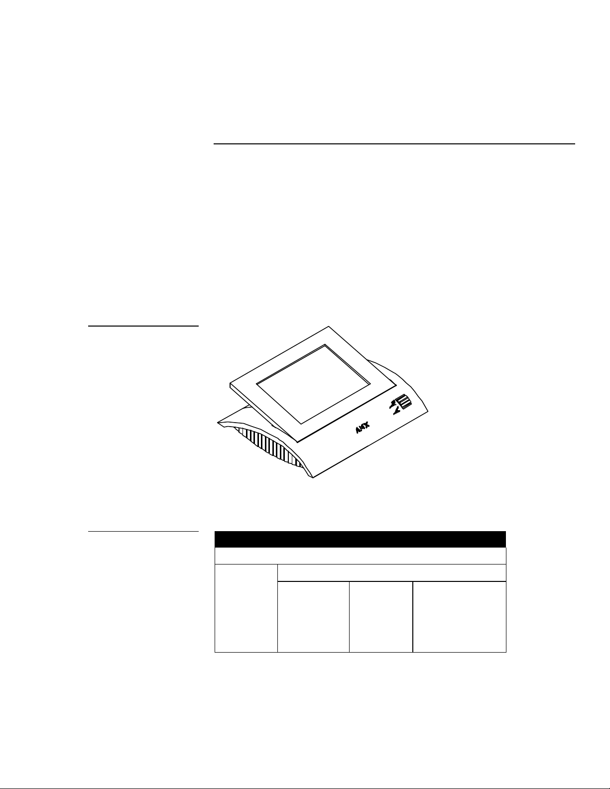
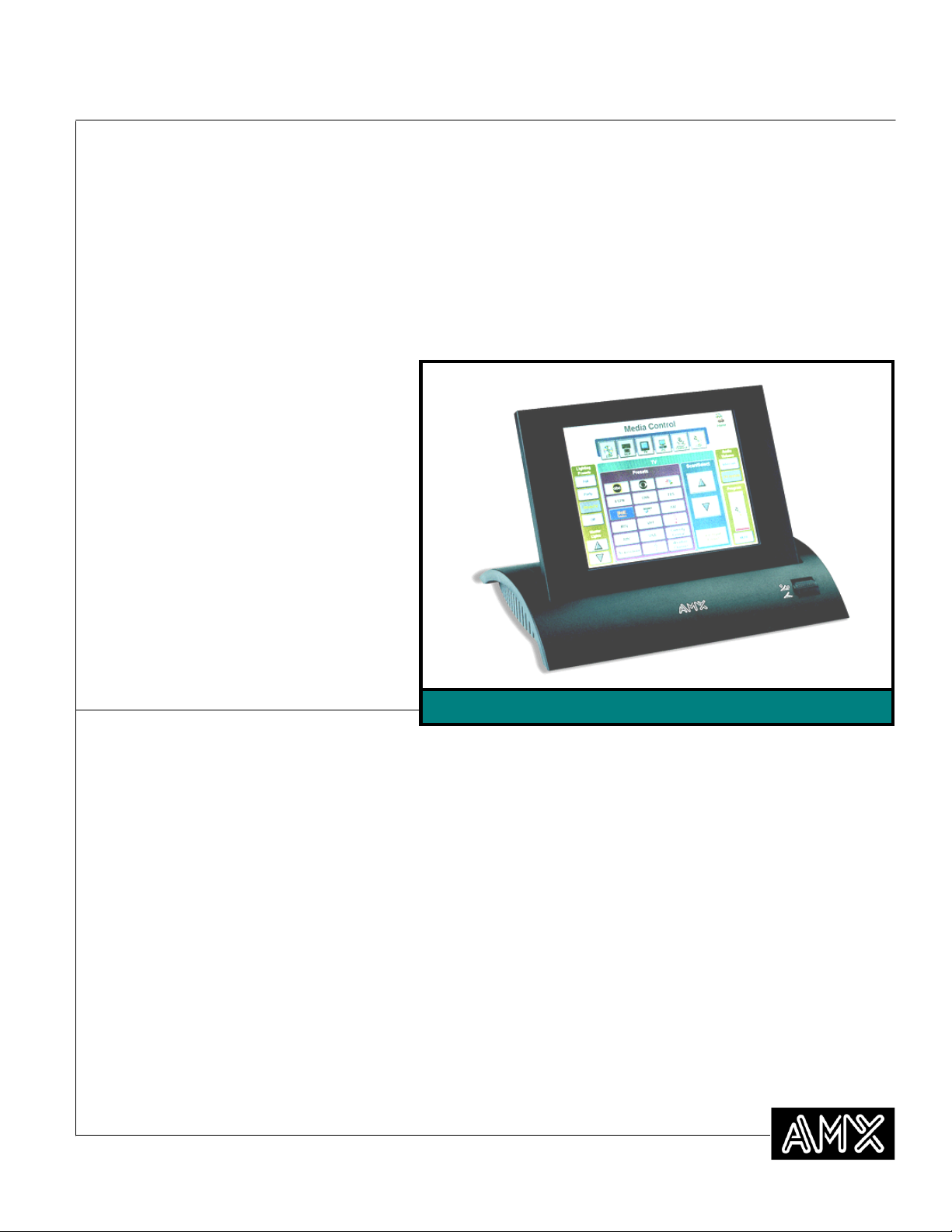
Figure 1
Color Active-Matrix
TiltScreen
Introduction
Overview
This manual describes procedures and software related to the new G3 firmware
installed in these panels. The Color Active-Matrix Touch Panels (CATPs) contain a
640 x 480 (HV) pixel, dedicated 256-color active-matrix liquid crystal display
(LCD). These self-contained enclosures use a microprocessor to control a wide
range of audiovisual products. With the TPDesign 3 custom Touch Panel design
program, you can create custom pages with buttons, icons, sliders, bargraphs, and
imported logos and drawings. Figure 1 shows an AXT-CA Color Active-Matrix
TiltScreen.
Figure 2 lists the panel types and product names described in this manual.
Figure 2
Color Active Touch Panel
types and product names
Color Active-Matrix LCD Touch Panels Introduction 1
Color Active Touch Panel types and product names
Panel types Product names
Standard Video Pushbutton
TiltScreen AXT-CA AXT-CV (not used)
UniMount AXU-CA AXU-CV AXU-CV/PB
AXU-CA/PB
Rack-mount AXM-CA AXM-CV AXM-CV/PB
AXM-CA/PB
Page 10

Features
and edited within TPDesign 3.
Touch Panel features include:
• 5.25" x 6.96" (133.45 mm x 176.89 mm) visible screen
• 256-color active-matrix 640 x 480 (HV) pixel LCD
• 12 programmable pushbuttons (8 on each side - except for the AXT series)
• Microsoft® mouse compatible (UniMount and rack-mount models only)
• Panel programming, screens, and drawings that can be archived with
TPDOC (MS-DOS) or designed with TPDesign 3 (Windows) touch panel
software program
• PAL- and NTSC-compatible video input port (optional)
• Optional two-way WavePack or one-way SmartPack modules for wireless
control (TiltScreen enclosure)
Note
These buttons with Unicode
Fonts can only be created
• Internal four-pin header for mouse control (UniMount and rack-mount
models only)
• Unicode Font support for Chinese and Arabic characters
2 Introduction Color Active-Matrix LCD Touch Panels
Page 11
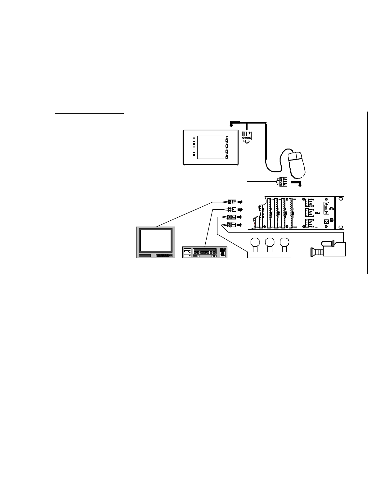
AXU-CA
(optional)
AXlink cable
AXCESS CardFrame
Television
VCR
Lighting
Camera
<<<< Factory installed connection
Figure 3
before installation.
Sample AXU-CA Touch Panel
and AXCESS Control System
Note
The optional mouse can be
used to design Touch Panel
pages and then removed
Applications
The AMX Color Active-Matrix Touch Panels control a wide variety of equipment
connected to an AXCESS Control System. Figure 3 shows a sample AXU-CA Touch
Panel and AXCESS Control System configuration.
Serial Mouse
What’s in this Manual
This manual contains the following sections:
• Installing the Touch Panel Includes installation, wiring, and cleaning
instructions.
• Touch Panel Basics Describes elements associated with the Touch Panel
operating system such as button types, message, and editor selection.
• Designing a Touch Panel Page Lists step-by-step instructions on how
to create a Touch Panel page, button, joystick, and bargraph.
• Touch Panel Program Reference Describes Touch Panel operations.
Color Active-Matrix LCD Touch Panels Introduction 3
Page 12

• AXCESS Programming Describes commands used to integrate Touch
Panel features into an AXCESS Control System.
• Replacing the Lithium Batteries Shows how to replace the lithium
batteries in the CATP.
• EXM-1MB Memory Upgrade Gives step-by-step instructions to install the
required EXM-1MB Memory Upgrade integrated circuits (ICs) in the CATP.
• Color Guidelines Provides helpful hints you can use to choose the best
Touch Panel colors.
• Specifications Describes the physical and operating characteristics of the
Touch Panels.
• Technical Support Identifies regions for technical support and provides
telephone numbers for each region.
What’s New
New sections added to this manual include:
• • Touch Panel Basics
• • Designing a Touch Panel Page
• • Touch Panel Program Reference
• • AXCESS Programming
All other revisions are identified by vertical margin bars as shown adjacent to this
paragraph.
4 Introduction Color Active-Matrix LCD Touch Panels
Page 13
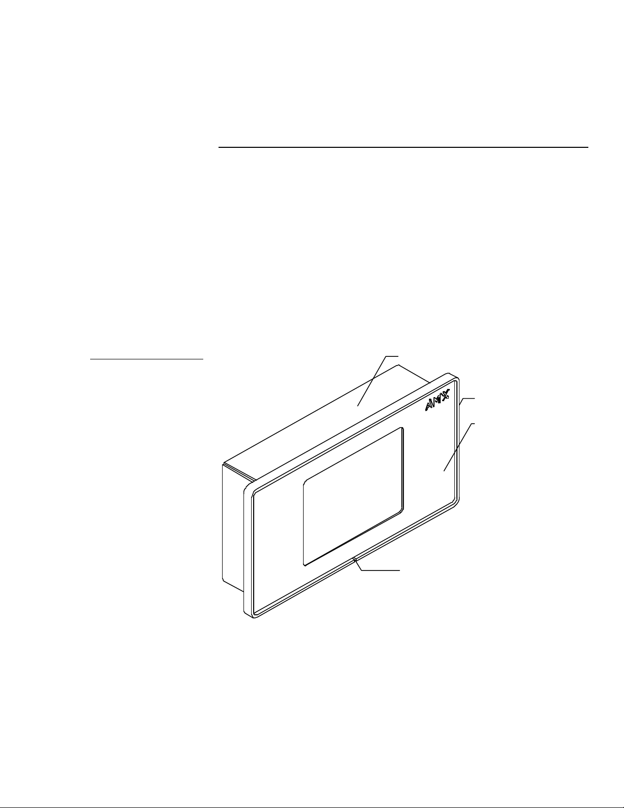
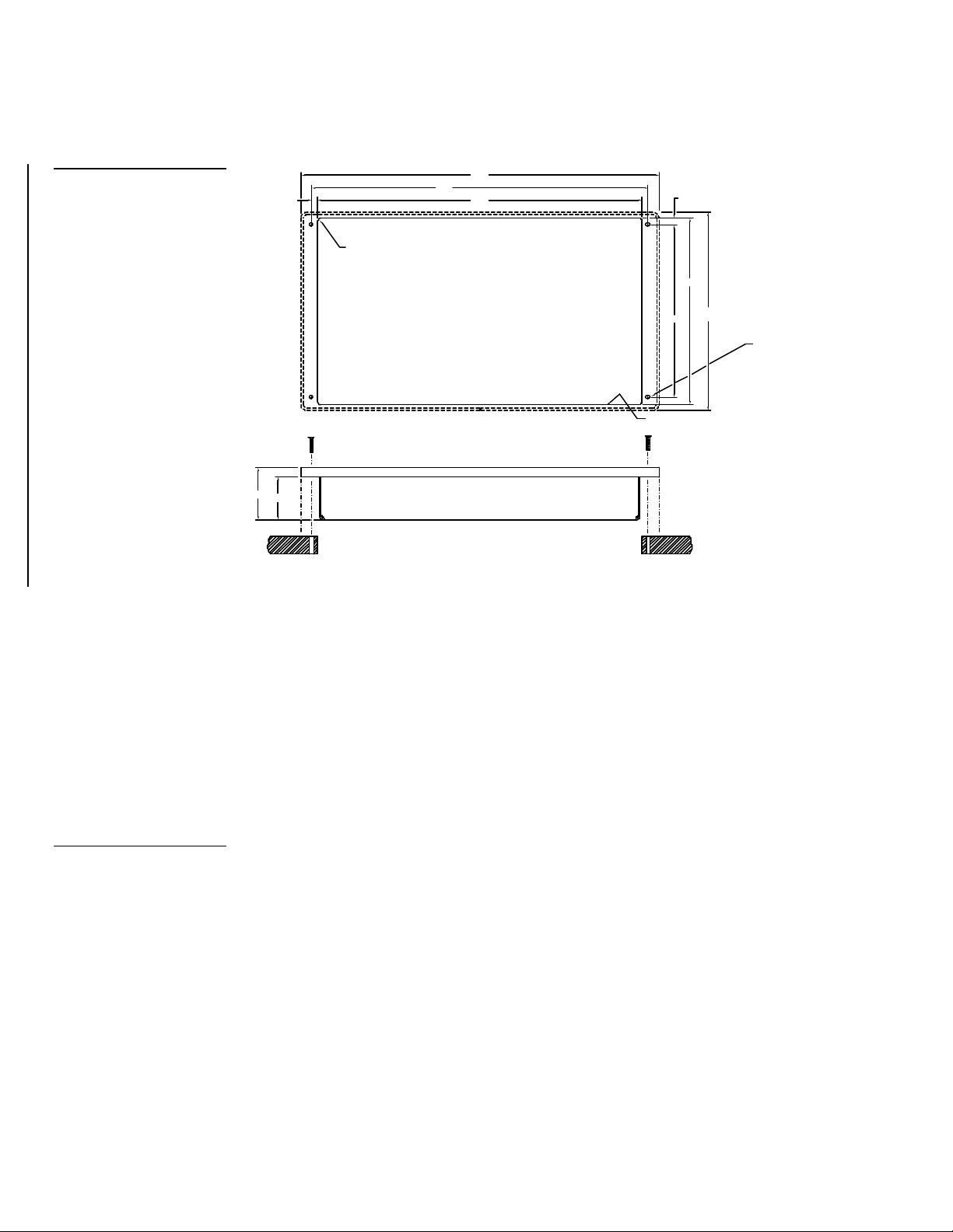
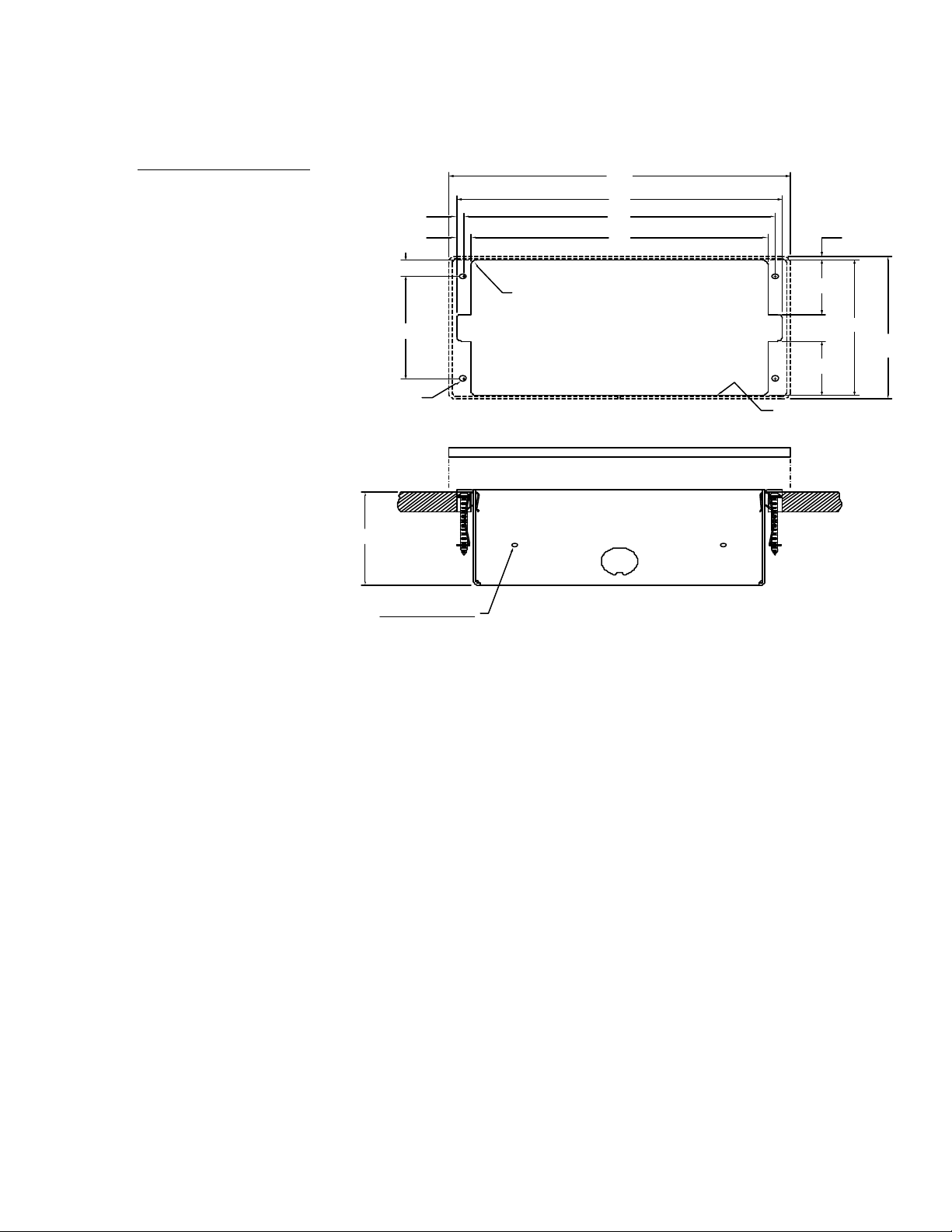
Low-profile back box
Release slot
Engraved
Figure 4
Installing Touch Panels
Overview
The section describes how to mount, wire, and clean Touch Panels.
Mounting the Touch Panels
The following paragraphs describe how to mount the UniMount and rack-mount
Touch Panels. The TiltScreen Touch Panel can be placed on any flat surface.
AXU-CV(/PB), AXU-CA(/PB), and low-profile back box
Mount the AXU-CV(/PB), AXU-CA(/PB), and low-profile back box (Figure 4):
AXU-CV(/PB) or AXUCA(/PB) and low-profile back
box
AXU-CV(/PB) or
AXU-CA(/PB)
bezel
1. Make a cutout in the surface according to the dimensions shown in Figure 5
for a low-profile back box.
Color Active-Matrix LCD Touch Panels Installing Touch Panels 5
Page 14
INSTALLATION METHOD
Figure 5
located at the bottom
AXU-CV(/PB) or AXUCA(/PB) and low-profile back
box cutout dimensions
12.60
(FRAME)
.23
.125 MAX RADIUS
IN CORNERS
1.79
1.48
11.85
11.40
CUTOUT
.25
6.50
6.88
(FRAME)
6.00
USE WHEN INSTALLING UNIT ON SOLID
SURFACES (PODIUM, DESK ETC.). FACE
FRAME AND LOW PROFILE BACKBOX
INSTALLED AS SINGLE "DROP-IN"
ASSEMBLY.
UNIT INSTALLS WITH
FOUR #6-32 SCREWS.
SUGGEST INSTALLATION
OF #6-32 THREADED
INSERTS AT LOCATIONS
SHOWN
Note
The CATP must always be
installed with the release slot
2. Insert a flat head screwdriver into the release slot on the AXU-CV(/PB)s or
AXU-CA(/PB)’s bezel and remove the engraved overlay.
3. Place the AXU-CV(/PB) or AXU-CA(/PB) into the cutout and mark the screw
insert positions as shown in Figure 4.
4. Remove the AXU-CV(/PB) or AXU-CA(/PB) and drill four #6-32 insert holes.
Then, place a threaded insert into each hole.
5. Attach the data and power wiring to the AXU-CV(/PB) or AXU-CA(/PB). Refer
to Wiring the Touch Panels for wiring diagrams and pinout descriptions.
6. Fasten the AXU-CV(/PB) or AXU-CA(/PB) and low-profile back box to the
surface using the #6-32 machine screws supplied with the enclosure.
7. Insert the engraved overlay back into the bezel.
8. Connect the AXlink wiring to the AMX Central Controller, and RS-232 wiring
(optional) to the external RS-232 device. The AXU-CV(/PB) or AXU-CA(/PB)
will beep when you apply power.
6 Installing Touch Panels Color Active-Matrix LCD Touch Panels
Page 15
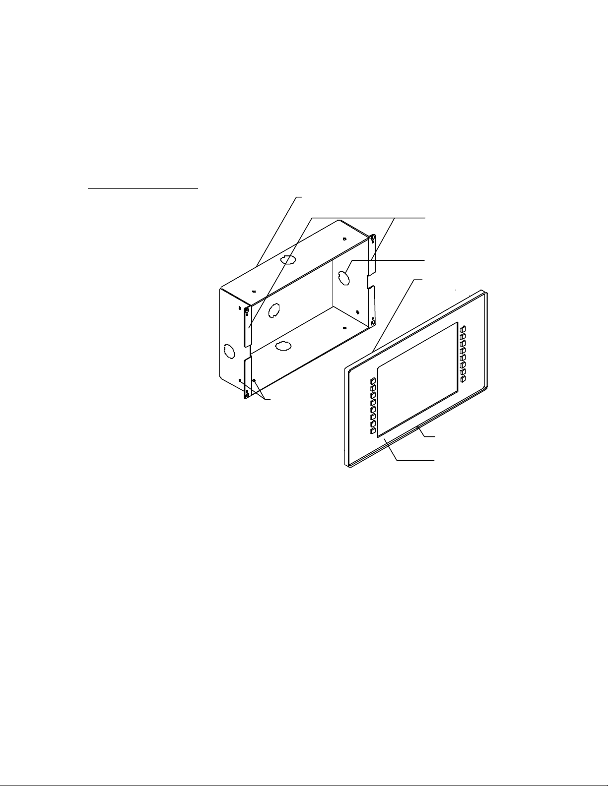
Release slot
flanges
Knockout
BB-TP1 UniMount Back Box enclosure
AXU-CA/PB bezel
Engraved overlay
holes
Figure 6
AXU-CV(/PB) or AXU-CA(/PB) and BB-TP1 (solid surfaces)
Mount the AXU-CV(/PB) or AXU-CA(/PB) and BB-TP1 (Figure 6) into a solid
surface:
AXU-CV/PB or AXU-CA/PB
and BB-TP1 UniMount Back
Box enclosure for solid
surfaces
Solid surface mounting
AXU-CV/PB or
Stud mounting
1. Cut the solid surface according to the cutout dimensions shown in Figure 7.
Color Active-Matrix LCD Touch Panels Installing Touch Panels 7
2. Insert a flat head screwdriver into the release slot on the AXU-CV(/PB) or
AXU-CA(/PB)’s bezel and remove the engraved overlay.
Page 16
THIRD ANGL
used as the basis for manufacture
INSTA
EASIL
PERM
EXPAN
SHEE
USE W
OF BACK BOX FOR STUD MOUNTING.
THIRD ANGLE
used as the basis for manufacture
INSTALLATION METH
USE WHEN INSTALLING UNIT ON SOLID
SURFACES (PODIUM, DESK ETC.). ALLO
PERMANENT INSTALLATION OF BACK B
WITH FACE FRAME AND ELECTRONICS
OF BACK BOX FOR STUD MOUNTING.
MOUNTING / MILLWORK S
AXU-CV COLOR ACTIVE W
(BACKBOX SECURED WIT
Mounting with Expansion Clips
Mounting with Screws
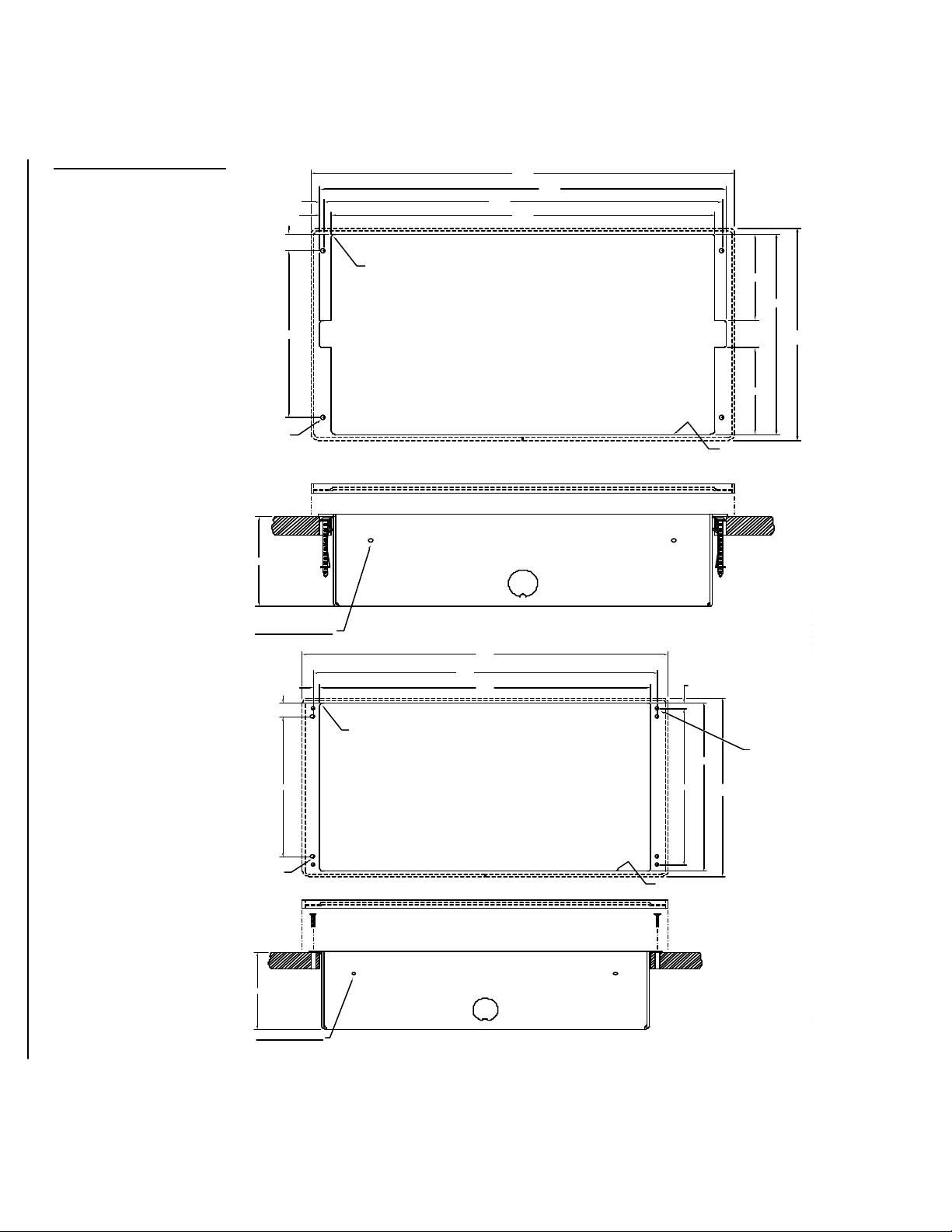
Figure 7
AXU-CV(/PB) or AXUCA(/PB), and BB-TP1 cutout
dimensions
12.60
(FRAME)
12.10
11.85.125
11.40.35
.55
.125 MAX RADIUS
IN CORNERS
2.80
6.50
5.40
.187 DIA
4 HOLES
2.94
STUD MOUNTING OPTION:
TWO .170 DIA HOLES PROVIDED ON ALL SIDES
.23
B
.55
A
.125 MAX RADIUS
IN CORNERS
5.40
6.88
(FRAME)
2.80
CUTOUT
WITH
NOTICE: This drawing is the property
of AMX CORPORATION. All information
contained herein that is not generally
known shall be confidential except to
the extent the information has been
previously established. This drawing
.25
6.50
may not be reproduced, copied or
6.88
(FRAME)
A RELEASED TO PRODUCTION
12.60
(FRAME)
11.85
11.40
B
A
6.00
DRAWN
CHECKED
APPD ENG
APPD QC
APPD MFG
DESCRIPTIONREV
UNIT INSTALLS WITH
FOUR #6-32 SCREWS.
SUGGEST INSTALLATION
OF #6-32 THREADED
INSERTS AT LOCATIONS
SHOWN (MARKED "B")
8 Installing Touch Panels Color Active-Matrix LCD Touch Panels
A
.187 DIA
4 HOLES
(MARKED "A")
2.94
STUD MOUNTING OPTION:
TWO .170 DIA HOLES PROVIDED ON ALL SIDES
B
A
B
CUTOUT
NOTICE: This drawing is the property
of AMX CORPORATION. All information
contained herein that is not generally
known shall be confidential except to
the extent the information has been
previously established. This drawing
may not be reproduced, copied or
EASILY REMOVABLE FOR SERVICING.
DRAWN
AM 6/21/96
CHECKED
APPD ENG
APPD QC
APPD MFG
DWG. NO.SIZE
SP094104
C
Page 17

3. Lay the AXU-CV(/PB) or AXU-CA(/PB) facedown onto a soft cloth and
remove the four screws from the low-profile back box. Remove the back box
and discard.
Note
The CATP must always be
installed with the release slot
located at the bottom.
Note
The BB-TP1 can also be
mounted to wood or metal
studs using the pre-drilled
stud mounting holes.
4. Place the BB-TP1 into the cutout and mark the threaded insert positions as
shown in Figure 7.
5. Remove the BB-TP1 and drill eight holes as shown in Figure 6. Then, place #6-
32 threaded inserts into the four holes marked ‘B’ in the cutout dimensions
illustration.
6. Disconnect the AXlink connector from the control system that supplies power
and data to the AXU-CV(/PB) or AXU-CA(/PB). Then, disconnect the DB-9
connector from the external RS-232 device connected to the AXU-CV(/PB) or
AXU-CA(/PB).
7. Remove one or more knockouts to accommodate the wiring as required.
8. Thread the incoming AXlink and RS-232 wiring through the BB-TP1 knockout.
9. Fasten the BB-TP1 to the solid surface with the mounting screws supplied with
the enclosure.
10. Connect the AXlink and RS-232 wiring to the AXU-CV(/PB) or AXU-CA(/PB)
circuit card. Refer to Wiring the Touch Panel for complete wiring information.
11. Fasten the AXU-CV(/PB) or AXU-CA(/PB) to the BB-TP1 with the #6-32
screws provided with the enclosure.
12. Insert the engraved overlay back into the bezel.
13. Connect the AXlink wiring to the AMX control system and RS-232 wiring to
the external RS-232 device. The AXU-CV(/PB) or AXU-CA(/PB) will beep
when you apply power.
Color Active-Matrix LCD Touch Panels Installing Touch Panels 9
Page 18
AXU-CV(/PB) or AXU/CA(/PB) and BB-TP1 (plasterboard)
OF BACK BOX FOR STUD MOUNTING.
Mount the AXU-CV(/PB) or AXU-CA(/PB) and BB-TP1 (Figure 8) into a
plasterboard surface (or equivalent).
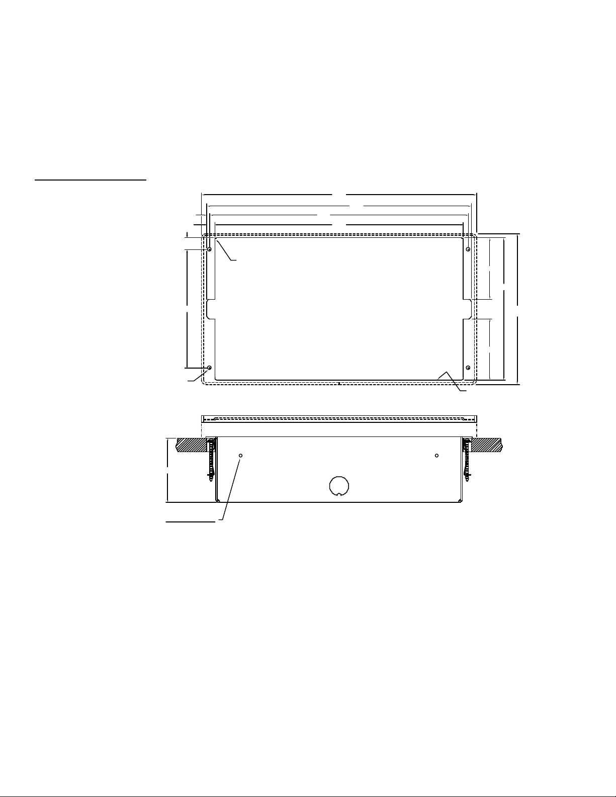
Figure 8
AXU-CV/PB and BB-TP1 for
plasterboard
2.94
.187 DIA
4 HOLES
12.60
(FRAME)
11.85.125
.55
.125 MAX RADIUS
IN CORNERS
5.40
12.10
11.40.35
2.80
6.50
6.88
(FRAME)
2.80
CUTOUT
10 Installing Touch Panels Color Active-Matrix LCD Touch Panels
STUD MOUNTING OPTION:
TWO .170 DIA HOLES PROVIDED ON ALL SIDES
1. Cut the surface according to the cutout dimensions shown in Figure 9.
Page 19
.125 [3.2 MM] MAX
CUTOUT
TWO .170 [4.3 MM] DIA HOLES PROVIDED ON
2.94
1.70
1.70
.125
4.25
7.10
7.46
7.80
.35
.170
.52
3.22
(FRAME)
(FRAME)
[74.7 MM]
[8.9 MM]
[180.3 MM]
8.187
4.50
Figure 9
AXU-CV(/PB) or AXUCA(/PB), and BB-TP1 cutout
dimensions
2. Insert a flat head screwdriver into the release slot on the AXU-CV(/PB)’s or
AXU-CA(/PB)’s bezel and remove the engraved overlay.
3. Lay the AXU-CV(/PB) or AXU-CA(/PB) facedown onto a soft cloth and
remove the four screws from the low-profile back box. Remove the back box
and discard.
4. Place the BB-TP1 into the cutout and mark the threaded insert positions as
shown in Figure 9.
5. Remove the BB-TP1 and drill four #6-32 insert holes. Then, place a threaded
insert into each hole.
6. Disconnect the AXlink connector from the AMX Central Controller that
supplies power and data to the AXU-CV(/PB) or AXU-CA(/PB). Then,
disconnect the DB-9 connector from the external RS-232 device connected to
the AXU-CV(/PB) or AXU-CA(/PB).
7. Thread the incoming AXlink and RS-232 wiring through the BB-TP1 knockout.
Color Active-Matrix LCD Touch Panels Installing Touch Panels 11
Page 20
Note
The CATP must always be
installed with the release slot
located at the bottom.
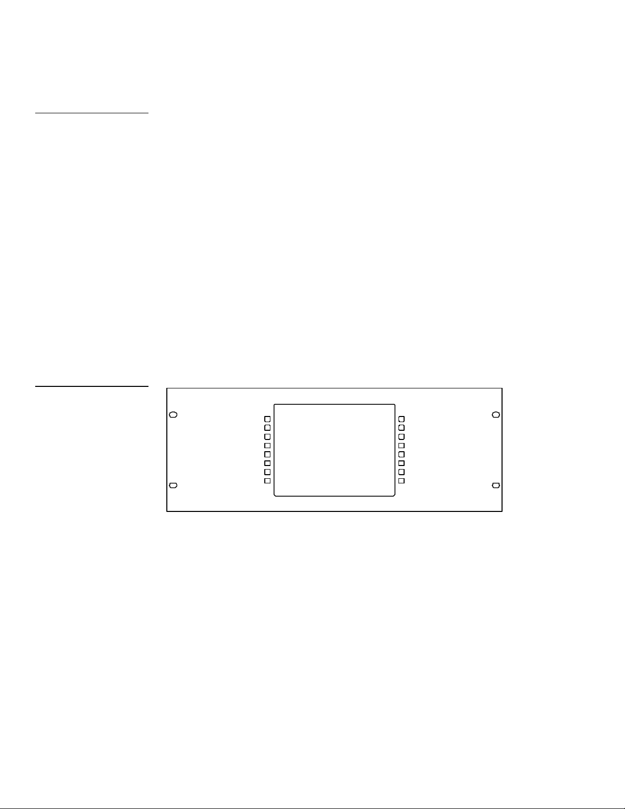
Figure 10
AXM-CV(/PB) or AXMCA(/PB) Rack-Mount CATP
8. Fasten the BB-TP1 to the plasterboard using the expansion screws supplied
with the enclosure.
9. Connect the AXlink and RS-232 wiring to the AXU-CV(/PB) or AXU-CA(/PB)
circuit card. Refer to Wiring the Touch Panel for complete wiring information.
10. Fasten the AXU-CV(/PB) or AXU-CA(/PB) to the BB-TP1 with the #6-32
screws supplied with the enclosure.
11. Insert the engraved overlay back into the bezel.
12. Connect the AXlink wiring to the AMX Central Controller and RS-232 wiring
to the external RS-232 device. The AXU-CV(/PB) or AXU-CA(/PB) will beep
when you apply power.
AXM-CV(/PB) or AXM-CA(/PB) (rack-mount)
Mount the AXM-CA(/PB) or AXM-CA(/PB) (Figure 10) rack-mount into an
electronic equipment rack.
1. Thread the incoming AXlink and RS-232 (optional) wiring through the
opening in the equipment rack.
2. Disconnect the AXlink connector from the AMX Central Controller that
supplies power and data to the AXM-CV(/PB) or AXM-CA(/PB). Then,
disconnect the DB-9 connector from the external RS-232 device connected to
the AXU-CV(/PB) or AXM-CA(/PB).
3. Connect the AXlink and RS-232 wiring to the AXM-CV(/PB) circuit card. Refer
to Wiring the Touch Panel for complete wiring information.
12 Installing Touch Panels Color Active-Matrix LCD Touch Panels
Page 21
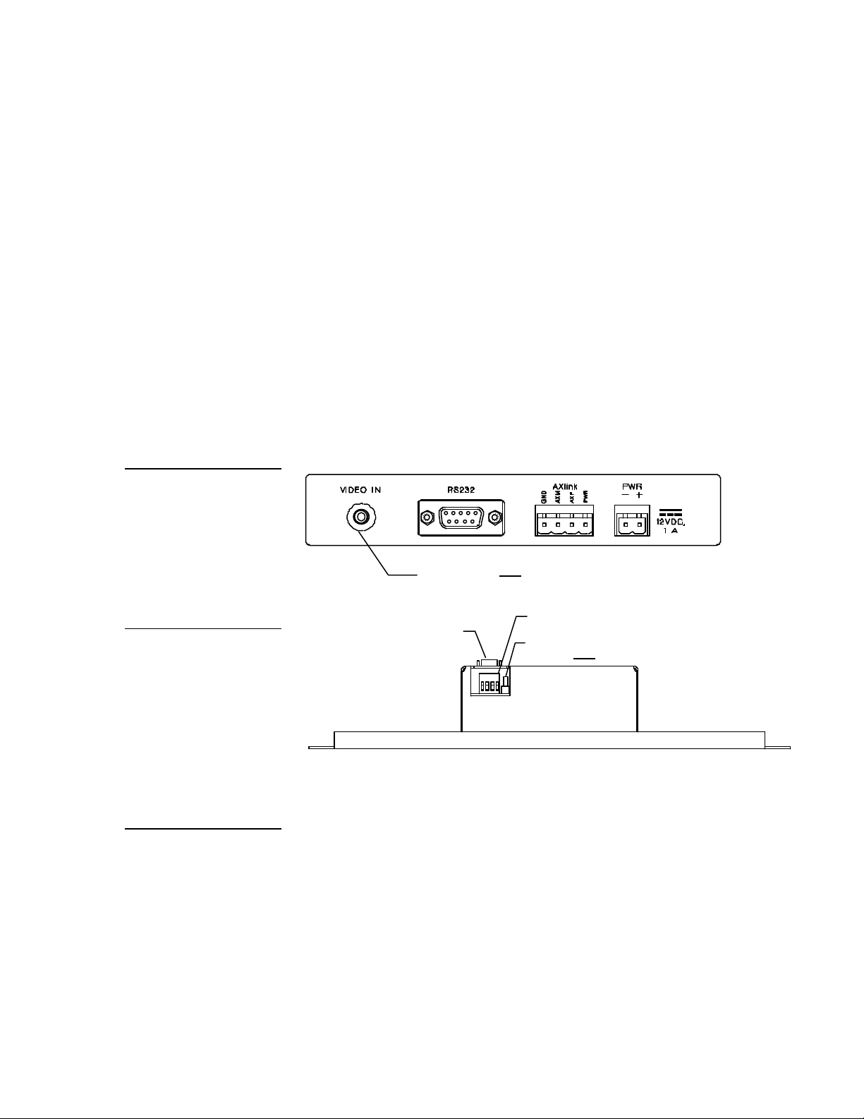
Rear view
Video models only
Top view
4-pin (male) AXlink connector
RS-232 (male) connector
models only
Figure 11
(rear view)
complete.
TiltScreen Color and Video
Touch Panel connectors
4. Insert the AXM-CV(/PB) or AXM-CA(/PB) into the rack. Line up the top left
and right screw holes and start the #6-32 screws. Then, start the bottom left
and right screws. Tighten all the screws after you start all the screws.
5. Connect the AXlink wiring to the AMX Central Controller and RS-232 wiring
to the external RS-232 device. The AXM-CV(/PB) or AXM-CA(/PB) will beep
when you apply power.
Wiring the Touch Panels
The CATPs use a four-pin AXlink connector for power and data. Figure 11 shows
the rear panel AXlink connector on the TiltScreen color active and color video
touch panels. Figure 12 shows the rear panel AXlink connector on the UniMount
and rack-mount color active and color video touch panels.
Figure 12
Rack-Mount CATP
connectors (top view)
Caution
Do not connect power to the
Touch Panel until the wiring is
complete. If you are using a
12 VDC power supply, apply
power to the Touch Panel
only after installation is
RCA Video connector - video
Preparing captive wires
You will need a wire stripper and flat-blade screwdriver to prepare and connect
the captive wires.
1. Strip 0.25 inch (6.35 mm) of wire insulation off all wires.
Color Active-Matrix LCD Touch Panels Installing Touch Panels 13
Page 22

2. Insert each wire into the appropriate opening on the connector according to
the connector.
Specifications section.
the wiring diagrams and connector types described in this section.
Caution
Do not over-torque the
screw. Doing so can bend
the seating pin and damage
Figure 13
Wiring guidelines 800 mA.
See the Specifications
section for power information.
Note
For information on the maximum power consumption of
each device, see the
3. Turn the flat-blade screws clockwise to secure the wire in the connector.
Wiring guidelines
Touch Panels require regulated 12 VDC power to operate properly. The AXCESS
Central Controller supplies power via the AXlink cable. The maximum wiring
distance between the control system and Touch Panel is determined by power
consumption, supplied voltage, and the wire gauge used for the cable. Figure 13
lists wire sizes and the maximum lengths allowable between the Touch Panel and
control system. The maximum wiring lengths for using AXlink power are based on
a minimum of 13.5 volts available at the control system’s power supply.
Wiring guidelines for Touch Panel (800 mA)
Wire size Maximum wiring length
18 AWG 146.71 feet (44.71 m)
20 AWG 92.8 feet (28.29 m)
22 AWG 57.9 feet (17.65 m)
24 AWG 34.5 feet (10.52 m)
If you install the Touch Panel farther away from the control system than
recommended in Figure 13, connect an external 12 VDC power supply as shown in
the wiring diagrams in this section.
14 Installing Touch Panels Color Active-Matrix LCD Touch Panels
Page 23
PWR (+)
AXM
AXP
GND (-)
Control system
PWR (+)
AXM
AXP
GND (-)
PWR (+)
AXM
AXP
GND (-)
PWR (+)
AXM
AXP
GND (-)
Control system
12 VDC power supply
PWR (+)
GND (-)
Touch Panel.
Figure 14
AXlink wiring diagram
Caution
Using the AXlink connector for data and power
Connect the control system’s AXlink connector to the AXlink connector on the rear
of the Touch Panel for data and 12 VDC power as shown in Figure 14.
If you are using power from
AXlink, disconnect the wiring
from the AXCESS Central
Controller before wiring the
Figure 15
AXlink and external 12 VDC
power supply wiring diagram
AXlink connector
Using the AXlink connector with an external 12 VDC power supply
Connect the control system’s AXlink connector to the AXlink connector on the rear
panel of the Touch Panel as shown in Figure 15.
AXlink connector
Use an external 12 VDC power supply when the distance between the control
system and Touch Panel exceeds the limits described in Figure 13. Make sure to
connect only the GND wire on the AXlink connector when using an external 12
VDC power supply. Do not connect the PWR wire to the AXlink connector’s PWR
(+) terminal.
Color Active-Matrix LCD Touch Panels Installing Touch Panels 15
Page 24
VIA_PADSTACK
NET
VIA_PADSTACK
NET
VIA_PADSTACK
NETNET
VIA_PADSTACK
NET
VIA_PADSTACK
NETNETNET
VIA_PADSTACK
NET
VIA_PADSTACK
NET
VIA_PADSTACK
NET
VIA_PADSTACK
NET
VIA_PADSTACK
NET
VIA_PADSTACK
NET
VIA_PADSTACK
NET
VIA_PADSTACK
NET
VIA_PADSTACK
NETNET
VIA_PADSTACK
NET
VIA_PADSTACK
NET
VIA_PADSTACK
NETNET
VIA_PADSTACK
NET
VIA_PADSTACK
NET
VIA_PADSTACK
NET
VIA_PADSTACK
NET
VIA_PADSTACK
NET
VIA_PADSTACK
NET
VIA_PADSTACK
NET
VIA_PADSTACK
NET
VIA_PADSTACK
NETNET
VIA_PADSTACK
NET
VIA_PADSTACK
NETNET
VIA_PADSTACK
NET
VIA_PADSTACK
NETNETNET
VIA_PADSTACK
NET
VIA_PADSTACK
NET
VIA_PADSTACK
NET
VIA_PADSTACK
NET
VIA_PADSTACK
NET
VIA_PADSTACK
NET
VIA_PADSTACK
NET
VIA_PADSTACK
NETNET
VIA_PADSTACK
NET
VIA_PADSTACK
NETNET
VIA_PADSTACK
NET
VIA_PADSTACK
NET
VIA_PADSTACK
NET
VIA_PADSTACK
NET
VIA_PADSTACK
NET
VIA_PADSTACK
NET
VIA_PADSTACK
NET
VIA_PADSTACK
NETNET
VIA_PADSTACK
NET
VIA_PADSTACK
NETNET
VIA_PADSTACK
NET
VIA_PADSTACK
NET
VIA_PADSTACK
NET
VIA_PADSTACK
NET
VIA_PADSTACK
NETNET
VIA_PADSTACK
NET
VIA_PADSTACK
NET
VIA_PADSTACK
NETNET
VIA_PADSTACK
NETNET
VIA_PADSTACK
NET
VIA_PADSTACK
NETNET
VIA_PADSTACK
NET
VIA_PADSTACK
NET
VIA_PADSTACK
NET
VIA_PADSTACK
NET
VIA_PADSTACK
NET
VIA_PADSTACK
NET
VIA_PADSTACK
NETNETNETNET
VIA_PADSTACK
NETNET
VIA_PADSTACK
NETNETNETNET
VIA_PADSTACK
NET
VIA_PADSTACK
NETNETNETNET
VIA_PADSTACK
NET
VIA_PADSTACK
NETNET
VIA_PADSTACK
NETNETNET
VIA_PADSTACK
NET
VIA_PADSTACK
NET
VIA_PADSTACK
NET
VIA_PADSTACK
NET
VIA_PADSTACK
NET
VIA_PADSTACK
NET
VIA_PADSTACK
NET
VIA_PADSTACK
NET
VIA_PADSTACK
NETNET
VIA_PADSTACK
NET
VIA_PADSTACK
NET
VIA_PADSTACK
NET
VIA_PADSTACK
NET
VIA_PADSTACK
NET
VIA_PADSTACK
NET
VIA_PADSTACK
NETNET
VIA_PADSTACK
NET
VIA_PADSTACK
NET
VIA_PADSTACK
NET
VIA_PADSTACK
NET
VIA_PADSTACK
NETNET
VIA_PADSTACK
NET
VIA_PADSTACK
NET
VIA_PADSTACK
NETNET
VIA_PADSTACK
NET
VIA_PADSTACK
NET
VIA_PADSTACK
NET
VIA_PADSTACK
NET
VIA_PADSTACK
NET
VIA_PADSTACK
NET
VIA_PADSTACK
NETNET
VIA_PADSTACK
NETNET
VIA_PADSTACK
NET
VIA_PADSTACK
NET
VIA_PADSTACK
NET
VIA_PADSTACK
NET
VIA_PADSTACK
NET
VIA_PADSTACK
NET
VIA_PADSTACK
NET
VIA_PADSTACK
NET
VIA_PADSTACK
NET
VIA_PADSTACK
NET
VIA_PADSTACK
NET
VIA_PADSTACK
NET
VIA_PADSTACK
NET
VIA_PADSTACK
NETNET
VIA_PADSTACK
NET
VIA_PADSTACK
NET
VIA_PADSTACK
NET
VIA_PADSTACK
NET
VIA_PADSTACK
NET
VIA_PADSTACK
NETNET
VIA_PADSTACK
NETNET
VIA_PADSTACK
NET
VIA_PADSTACK
NET
VIA_PADSTACK
NET
VIA_PADSTACK
NET
VIA_PADSTACK
NETNETNET
VIA_PADSTACK
NET
VIA_PADSTACK
NET
VIA_PADSTACK
NET
VIA_PADSTACK
NET
VIA_PADSTACK
NETNETNETNETNET
VIA_PADSTACK
NET
VIA_PADSTACK
NETNET
VIA_PADSTACK
NETNET
VIA_PADSTACK
NETNETNET
VIA_PADSTACK
NETNET
VIA_PADSTACK
NET
VIA_PADSTACK
NET
VIA_PADSTACK
NETNET
VIA_PADSTACK
NET
VIA_PADSTACK
NETNET
VIA_PADSTACK
NET
VIA_PADSTACK
NET
VIA_PADSTACK
NET
VIA_PADSTACK
NET
VIA_PADSTACK
NET
VIA_PADSTACK
NET
VIA_PADSTACK
NET
VIA_PADSTACK
NET
VIA_PADSTACK
NET
VIA_PADSTACK
NET
VIA_PADSTACK
NET
VIA_PADSTACK
NET
VIA_PADSTACK
NET
VIA_PADSTACK
NET
COMPONENTCOMPONENTCOMPONENT
1411B2B1U24U1P1U3U19
U4J2J4
J2A
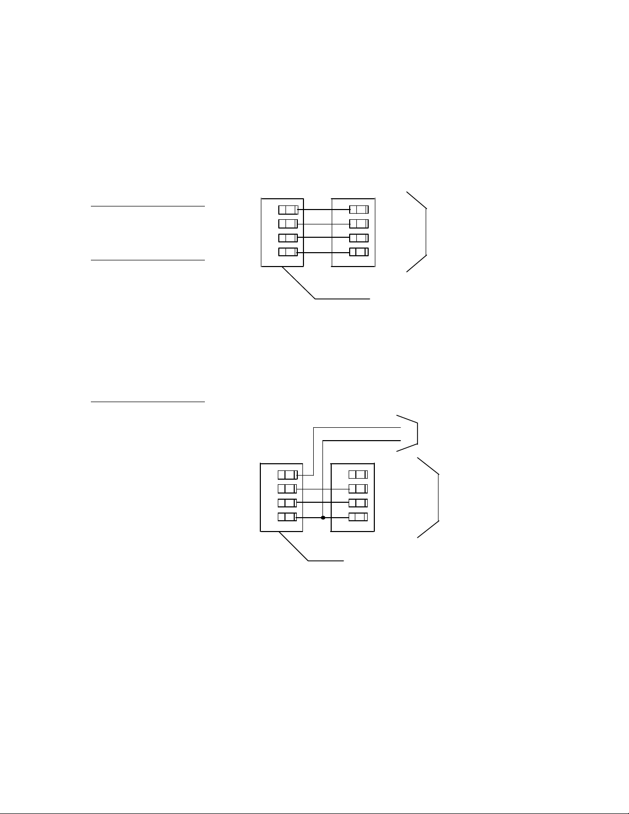
header
Connector side of circuit card
DB-9 connector (male)
TXD
RXD
GND
+12VDC
4 and 7 (+12)
3 (RXD)
5 (GND)
2 (TXD)
Pin 1
Figure 16
Four-pin header location on
the UniMount and rack-mount
Touch Panel circuit card
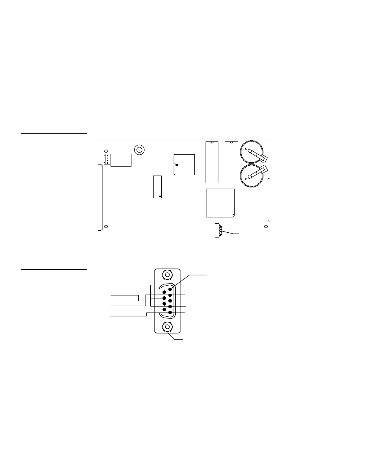
Using the UniMount and rack-mount 4-pin header for mouse control
Figure 16 shows the location of the four-pin header on the UniMount and rackmount Touch Panels. The four-pin header supports Microsoft serial mouse control
devices. Figure 17 for DB-9 wiring diagram. Figure 18 lists the four-pin header and
DB-9 connector (male) pinouts
4-pin
Figure 17
Circuit connector wiring
diagram
16 Installing Touch Panels Color Active-Matrix LCD Touch Panels
Page 25

Figure 18
Four-pin header and DB-9
connector pinouts
Four-pin header and DB-9 connector pinouts
Fourpin
header
Signal Function DB-9 connector (male)
pins
1 PWR +12 VDC power 4 and 7 (strap)
2 TXD Transmit data 3
3 RXD Receive data 2
4 GND Ground 5
Cleaning the Touch Overlay
After installing the Touch Panel, you should clean the touch overlay. To clean the
touch overlay:
1. Disconnect the AXlink and optional video connectors from the CATP.
2. Using a cotton cloth, spray a small amount of cleaning solution consisting of
50% isopropyl alcohol and 50% water onto the cloth.
3. Clean the touch overlay with the damp cloth. Then, wipe the touch overlay
with a dry cloth.
4. Reconnect the AXlink and optional video connectors to the CATP.
Color Active-Matrix LCD Touch Panels Installing Touch Panels 17
Page 26

18 Installing Touch Panels Color Active-Matrix LCD Touch Panels
Page 27
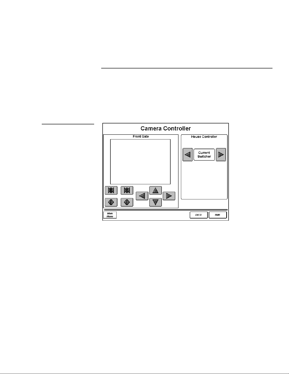
Figure 19
Sample Touch Panel page
Touch Panel Basics
Overview
This section contains descriptions and illustration examples of Touch Panel pages
(Figure 19), buttons, message bars, and keypads. You can use the Touch Panel’s
onboard editor or the TPDesign 3 software program to create custom pages.
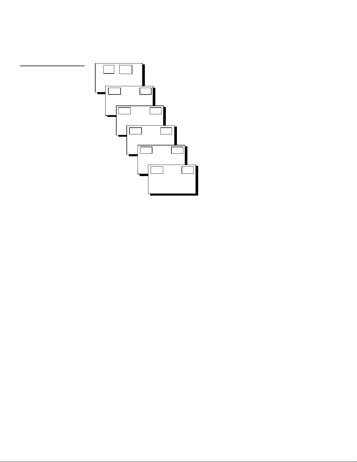
Touch Panel Pages
You can create buttons, bargraphs, sliders, and drawings with the Touch Panel
editor. The number of objects depends on the type and quantity of external devices
you want to control with the Touch Panel and AXCESS Central Controller. When
you create multiple pages, you must link them with buttons. Figure 20 shows how
five Touch Panel pages are linked to the Main page. The illustration shows how
each page has a button that flips to the next page, and one that flips back to the
previous page.
Color Active-Matrix LCD Touch Panels Touch Panel Basics 19
Page 28
Main Page
Page
Page 2
Page 3
Page 1
Page 4
Page 2
Page 5
Page 3
Page 4
Page 1
Figure 20
linked buttons
Touch Panel pages with
Main
Main
Page 1
Page 2
Page 3
Page 4
Main
Page 5
Standard Buttons
Standard buttons are rectangles, rectangle variations, and other geometric shapes
that you can create with the Touch Panel. Buttons are set with attributes, which
means that there is control system feedback when you touch the button.
General Buttons
General buttons are part of the Touch Panel program and cannot be changed. You
use general buttons to specify panel communication parameters and create or
revise pages. Some button examples include the message bar, adjustment, keypad,
page menu, decision, status, and keyboard.
Selection buttons
Selection buttons (Figure 21) appear throughout the color active and color active
video Touch Panel software program to open pages, activate YES/NO prompt
messages or set communication parameters.
20 Touch Panel Basics Color Active-Matrix LCD Touch Panels
Page 29
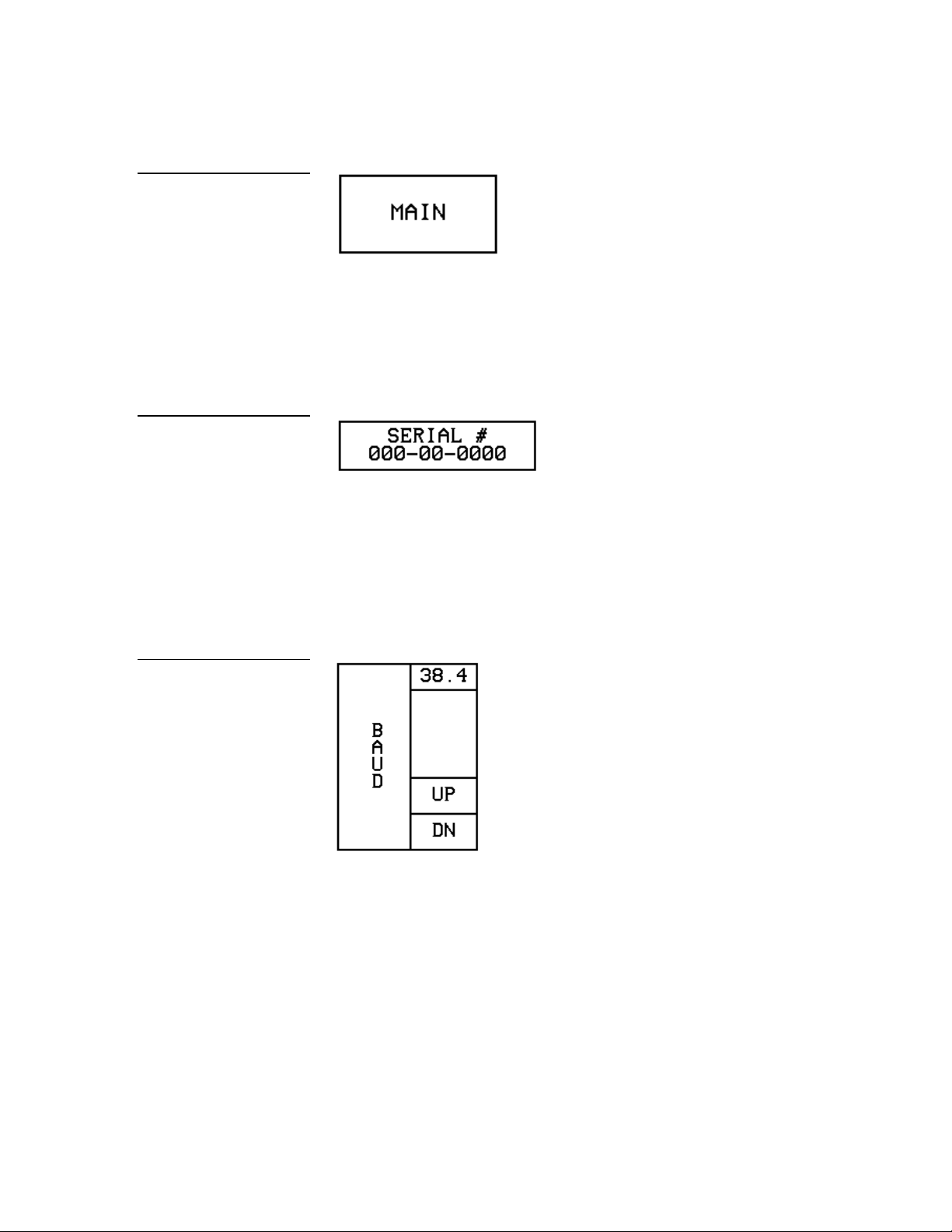
Figure 21
Selection button example
Figure 22
Information button example
Information buttons
Information buttons contain serial numbers and firmware version information.
Figure 22 shows the serial number information button in the Setup page.
Adjustment buttons
You can use the UP and DN buttons to set adjustment buttons. The adjustment
button example in Figure 23 sets the baud rate for the RS-232 connector on the
Touch Panel.
Figure 23
Adjustment button example
Keypad buttons
The keypad button opens a keypad (Figure 24) so you can enter a password or
value assignment. All keypad buttons are interactive except for the entry display.
Color Active-Matrix LCD Touch Panels Touch Panel Basics 21
Page 30

Entry display
Keypad entry (0 - 9)
CLEAR – Resets entry to 0
ENTER – Processes entry if correct
Figure 24
Decision button example
Keypad example
Figure 25
Decision buttons
Decision buttons (Figure 25) appear when an operation has two options.
Decision buttons appear when you send or receive a drawing, designate a
communication protocol or perform an operation error.
Figure 26
Status button example
Status buttons
Status buttons (Figure 26) appear when you try to perform operations that do not
function correctly.
NO COMMUNICATION
TOUCH SCREEN TO CONTINUE
22 Touch Panel Basics Color Active-Matrix LCD Touch Panels
Page 31
Note
not see the MAIN page.
If you have a preprogrammed panel, you may
Figure 27
Designing a Touch Panel Page
Overview
Use the step-by-step instructions to create Touch Panel pages, buttons, joysticks,
bargraphs, and set page color attributes. For in-depth information on all the
operations available on the Touch Panel, read through the Touch Panel Program
Reference section to learn about all the operations and techniques available to
design Touch Panel pages.
Activating the Edit Button
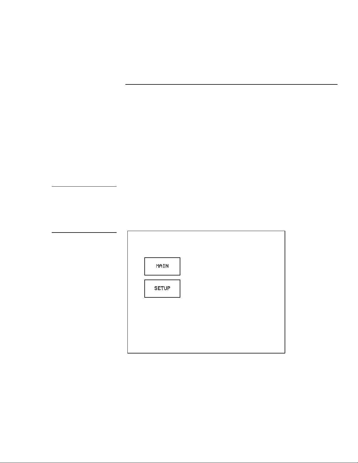
Before you design a Touch Panel page you must activate the EDIT button which
contains options to add and configure Touch Panels and buttons. When you
power up the Touch Panel, the first page you see is the MAIN page shown in
Figure 27. Refer to Edit button and Go to information in the Touch Panel Program
Reference section if the MAIN page does not appear.
MAIN page
Color Active-Matrix LCD Touch Panels Designing a Touch Panel Page 23
Page 32

Figure 28
keypad
SETUP page
1. Press SETUP in the MAIN page to open the SETUP page shown in Figure 28.
2. In the above page, press PROTECTED SETUP to open the password keypad
shown in Figure 29.
Figure 29
SETUP page and password
24 Designing a Touch Panel Page Color Active-Matrix LCD Touch Panels
Page 33

Note
previous page.
If you press ENTER after
typing in an incorrect
password, you are
immediately returned to the
Figure 30
PROTECTED SETUP page
3. Type 1988 in the keypad, and press ENTER to open the PROTECTED SETUP
page (Figure 30). For information on changing the password, refer to Touch
Panel Program Reference section. If you enter a wrong number, press CLEAR
and re-enter the number.
4. Press EDITOR to enable the Editor mode. The active mode of the EDITOR
button is shown in Figure 31.
5. Press EXIT to close the PROTECTED SETUP page and return to the SETUP
page in Editor mode.
Color Active-Matrix LCD Touch Panels Designing a Touch Panel Page 25
Page 34

Figure 31
Active EDITOR button in the
PROTECTED SETUP page
Figure 32
6. Press EXIT twice to return to the MAIN page. The EDIT button appears at the
top of the MAIN page, indicating that the Editor mode is active (Figure 32).
MAIN page with EDIT button
7. Press the EDIT button to open the Edit bar, which appears at the top of the
page (Figure 33).
26 Designing a Touch Panel Page Color Active-Matrix LCD Touch Panels
Page 35

Edit bar
Figure 33
MAIN PAGE and Edit bar
Creating a Page
Use the PAGE menu option in the Edit bar to create Touch Panel pages.
Figure 34
PAGE menu options
Adding a page
1. Press PAGE on the Edit bar to open the Page menu options(Figure 34).
Color Active-Matrix LCD Touch Panels Designing a Touch Panel Page 27
Page 36

Figure 35
as popup pages and buttons.
Keyboard
Note
Page naming does not allow
you to change the font type,
as is available for such things
2. Press the ADD option to add a new Touch Panel page. This command opens
the keyboard (Figure 35). Use the keyboard to enter a name for the new page.
3. Type NEW PAGE (Figure 36) using the keyboard. A page name can be up to 20
characters.
Figure 36
Keyboard: NEW PAGE
28 Designing a Touch Panel Page Color Active-Matrix LCD Touch Panels
Page 37

Figure 37
Edit bar
Figure 38
PAGE menu options
4. Press EXIT CHANGE to add NEW PAGE to Touch Panel memory, close the
keyboard, and return to the NEW page.
5. Press EXIT on the Edit bar.
Setting the page color
1. Press EDIT to open the Edit bar shown in Figure 37.
2. Press PAGE on the Edit bar to open the PAGE menu options shown in
Figure 38.
3. Press the PAGE COLOR option to open the color options shown in Figure 39.
Color Active-Matrix LCD Touch Panels Designing a Touch Panel Page 29
Page 38

Figure 39
Color options
4. Select a page color from the palette. The page automatically changes to the new
color.
Creating a Button
Use the BUTTON menu option in the Edit bar to create Touch Panel buttons.
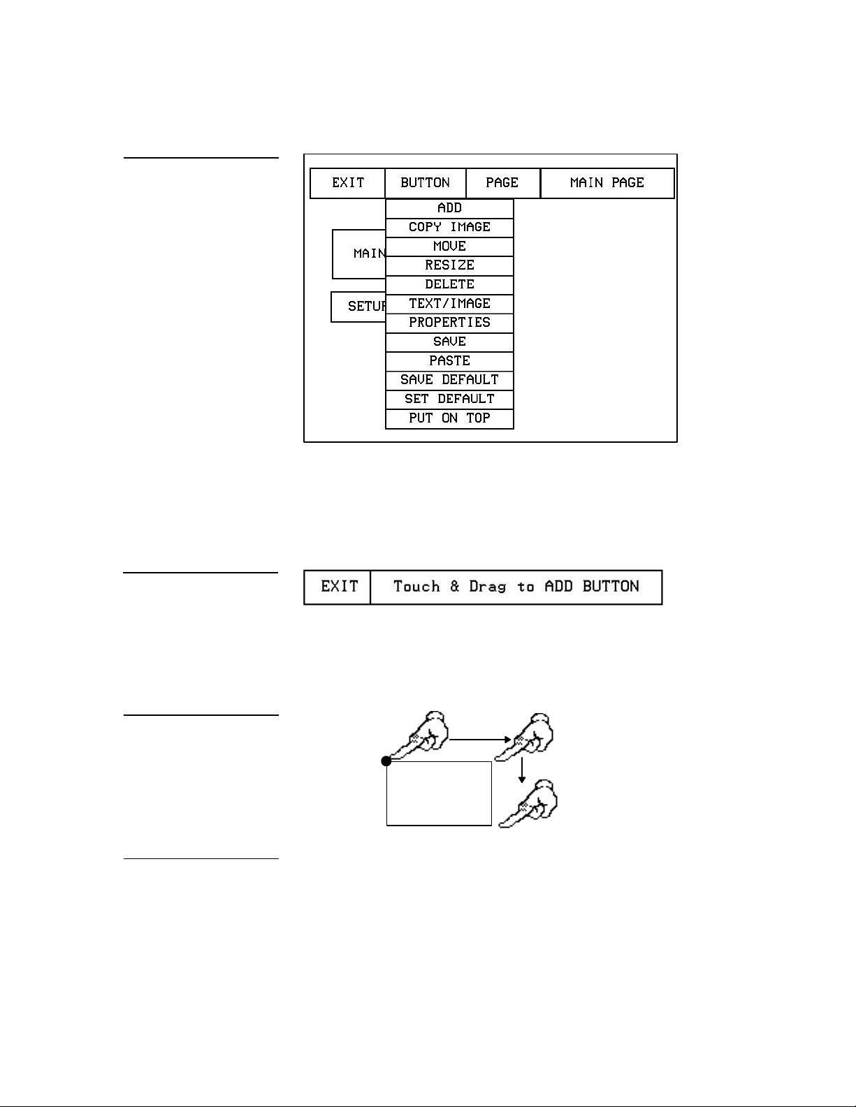
Adding a button
1. Press EDIT to open the Edit bar (Figure 37).
2. Press BUTTON on the Edit bar to open the BUTTON menu options shown in
Figure 40.
30 Designing a Touch Panel Page Color Active-Matrix LCD Touch Panels
Page 39
Height
Touch Point
Figure 40
ADD BUTTON message bar
button at this time.
BUTTON menu options
3. Press ADD to add a button to the new page. The message bar shown in Figure
41 appears. Touch and drag to add a button. The first touch point is the upperleft corner of the button.
Figure 41
Figure 42
Add a button example
Note
You can add more than one
4. Push on the panel and drag your finger horizontally and down across the
screen to set the height and width of the button, as shown in Figure 42.
Width
5. Release your finger from the panel to record the button dimensions into the
panel memory.
6. Press EXIT in the Edit bar.
Color Active-Matrix LCD Touch Panels Designing a Touch Panel Page 31
Page 40

drag to resize.
Figure 43
bar
BUTTON menu options
Resizing a button
1. Press EDIT to open the Edit bar.
2. Press BUTTON on the Edit bar to open the menu options shown in Figure 43.
Figure 44
RESIZE BUTTON message
Figure 45
Resizing a button
3. Press the RESIZE option to resize the button when the message bar (Figure 44)
appears.
4. Push the edge of the button, and drag your finger horizontally across the
screen and down to resize the button (Figure 45).
Touch any edge and
32 Designing a Touch Panel Page Color Active-Matrix LCD Touch Panels
Page 41

Figure 46
BUTTON menu options
5. Release your finger from the panel to record the button dimensions into the
panel memory.
6. Press EXIT in the Edit bar.
Button Properties
Use the PROPERTIES option of the BUTTON menu in the Edit bar to set button
borders, page flips, button colors for channel on and off conditions, and channel
and variable text codes.
Setting the button properties
1. Press EDIT to open the Edit bar (Figure 37).
2. Press BUTTON on the Edit bar to open the BUTTON menu options shown in
Figure 46.
3. Press PROPERTIES to open the Edit bar shown in Figure 47.
Figure 47
PROPERTIES message bar
4. Press the button you just added to open the BUTTON PROPERTIES page
shown in Figure 48. This page lists the properties of the selected button.
Color Active-Matrix LCD Touch Panels Designing a Touch Panel Page 33
Page 42

Figure 48
other button border options.
BUTTON PROPERTIES
page
Setting the border
1. Press BORDER in the BUTTON PROPERTIES page to open the BUTTON
BORDER options pages shown in Figure 49.
Figure 49
BUTTON BORDER options
pages
Note
Use the MORE button to view
34 Designing a Touch Panel Page Color Active-Matrix LCD Touch Panels
Page 43
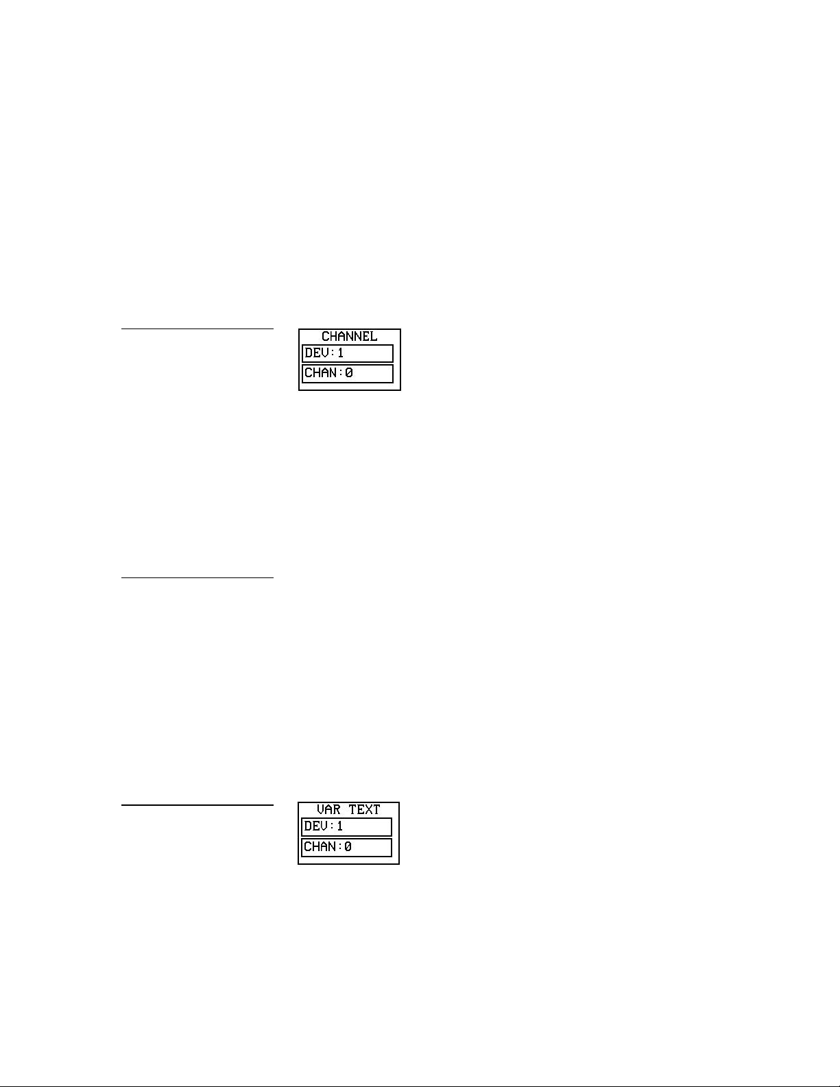
Figure 50
CHANNEL code buttons
2. Press 3D RECTANGLE 1 to set the button border to 3D RECTANGLE 1 style.
The BORDER button in the BUTTON PROPERTIES page reflects the selected
border type. In this case, the button changes to the 3D rectangle border.
Setting the channel code
1. The two fields to be set for the button channel code are DEV (device) and
CHAN (channel) as shown in Figure 50.
2. Press DEV to open a keypad and set the device number.
3. Type 1, 2,3, or 4 in the keypad. The device number specifies the device for
which the selected channel’s feedback is displayed.
4. Press ENTER to store the device code in memory, close the keypad, and return
to the BUTTON PROPERTIES page.
5. Press CHAN to open a keypad and set the channel number.
Note
The channel code(s) for nonactive buttons is 0, and active
buttons is1 through 255.
Figure 51
VARIABLE TEXT code
buttons
6. Type a channel value of 1 to 255 in the keypad. The AXCESS software
program uses the channel code number to identify the button and its
operations.
7. Press ENTER to store the channel code in memory, close the keypad, and
return to the BUTTON PROPERTIES page.
Setting the variable text code
1. The two fields to be set for the button variable text code are DEV (device) and
CHAN (channel) as shown in Figure 51.
2. Press DEV to open a keypad and set the device number.
Color Active-Matrix LCD Touch Panels Designing a Touch Panel Page 35
Page 44
Flip menu button
Figure 52
appear.
Page FLIP boxes
3. Type 1, 2, 3, or 4 in the keypad. The device number specifies the device
for which the selected channel’s feedback is displayed.
4. Press ENTER to store the device number in memory, close the keypad, and
return to the BUTTON PROPERTIES page.
5. Press CHAN to open a keypad and set the channel number.
6. Type a channel value of 1 to 255 in the keypad. The AXCESS software
program uses the channel code number to identify the button and its
operations.
7. Press ENTER to store the channel code in memory, close the keypad, and
return to the BUTTON PROPERTIES page.
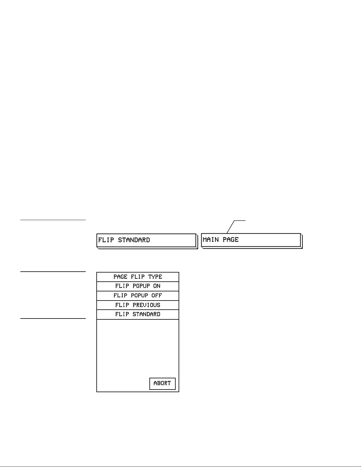
Setting the page flip
1. Press the left Page FLIP box in the Button Properties page (Figure 52) to open
the Page Flip Type list (Figure 53).
Figure 53
PAGE FLIP TYPE list
Note
When selecting the FLIP
PREVIOUS option in the
Page FLIP box, the POPUP
PAGE menu does not
36 Designing a Touch Panel Page Color Active-Matrix LCD Touch Panels
Page 45

2. Press FLIP STANDARD.
has not been created.
Note
The right page FLIP will
display the existing Touch
Panel pages. If the desired
page is not present, then it
Figure 54
BUTTON PROPERTIES
page
3. Press the right page FLIP box (Figure 52) to open the PAGE FLIP TYPE list
(Figure 53).
4. Press MAIN PAGE to set the page flip to the MAIN page.
Setting the button colors for channel-off conditions
1. Press the button to open the BUTTON PROPERTIES page shown in Figure 54.
2. Press BORDER in the COLOR (CHANNEL OFF) section of the BUTTON
PROPERTIES page (Figure 55).
Figure 55
CHANNEL OFF/ON COLOR
settings box
3. The color options (Figure 56) appear.
Color Active-Matrix LCD Touch Panels Designing a Touch Panel Page 37
Page 46

Figure 56
Color options
4. Press black to set the border color to black.
5. Press the FILL button in the BUTTON PROPERTIES page to re-open the color
options.
6. Press white to set the fill color to white.
7. Press the TEXT button to re-open the color options.
8. Press red to set the text color to red.
9. Press EXIT SAVE CHANGE in the BUTTON PROPERTIES page to store the
new button properties in memory and return to the current page.
10. Press EXIT on the Edit bar to exit PROPERTIES mode.
Adding text to a button
Use the BUTTON OPTION in the Edit bar to add text to buttons, joysticks, and
bargraphs.
1. Press EDIT to open the Edit bar.
2. Press BUTTON on the Edit bar to open the BUTTON menu options list as
shown in Figure 57.
38 Designing a Touch Panel Page Color Active-Matrix LCD Touch Panels
Page 47

Figure 57
TEXT/IMAGE message bar
BUTTON menu options
Figure 58
3. Press TEXT/IMAGE to add text in the selected button. The message bar shown
in Figure 58 appears.
Figure 59
TEXT/IMAGE page
4. Press the on-screen button to open the TEXT/IMAGE page shown in Figure 59.
Color Active-Matrix LCD Touch Panels Designing a Touch Panel Page 39
Page 48

Figure 60
pages.
TPDesign 3.
Keyboard
Note
The CHANGE FONT key
only appears when changing
the font of a function button
and does not apply to popup
5. Press TEXT OFF to open the keyboard shown in Figure 60.
Note
You can not create or edit
buttons with Unicode Fonts
within the Touch Panel. Any
use of the TEXT/IMAGE
button to alter or create a
Unicode Font supported
button must be done in
6. Type MAIN PAGE. The text appears in the message box at the top of the
keyboard. If you exceed the space in the button, the Touch Panel generates an
error message. Change the size of the button or reduce the text string to clear
the error message.
7. Press EXIT CHANGE to close the keyboard and return to the TEXT/IMAGE
page.
8. Press MAKE ON SAME AS OFF to set the text for both On and Off states of the
button.
9. Press EXIT SAVE CHANGE to close the TEXT/IMAGE page and return to the
NEW page.
10. Press EXIT in the Edit bar to exit Edit Text/Image mode.
40 Designing a Touch Panel Page Color Active-Matrix LCD Touch Panels
Page 49

Button Properties for External Buttons
Type(s) sections.
Note
Although these buttons don't
appear on-screen, their
functionality can be set just
as any other button on the
Touch panel. They will have
no on-screen presence with
such things as colors,
borders, and names. For
further information on the
PROPERTIES page features
see Properties Page-Button
Figure 61
Joystick
If your Touch Panel comes with external buttons, these can be configured with
features similar to on-screen buttons, for more information see the Creating a Button
subsection. Use the PROPERTIES option to assign properties to external
pushbuttons. The BUTTON OPTIONS and VARIABLE TEXT features within the
PROPERTIES page will not appear. Although the Border and Color sections of this
page appear, they are of no use by external buttons since they do not appear onscreen.
Creating a Joystick
You can create a joystick with the BUTTON TYPE option in the BUTTON
PROPERTIES page. Joysticks (Figure 61) are vertical and horizontal direction
controllers you use for camera operations such as pan and tilt.
Before you start, make sure to connect the Touch Panel to your AXCESS Central
Controller. Otherwise, the joystick will not work properly. For more information,
refer to the Touch Panel Program Reference section in this manual.
Adding a joystick to a page
1. Create a new button using the ADD option in the BUTTON menu described in
the Creating a Button subsection.
2. Press BUTTON on the Edit bar to open the BUTTON menu options shown in
Figure 62.
Color Active-Matrix LCD Touch Panels Designing a Touch Panel Page 41
Page 50

Figure 62
BUTTON menu options
Figure 63
PROPERTIES message bar
3. Press the PROPERTIES option to open the message shown in Figure 63.
4. Next press the new button.
5. Press BUTTON TYPE (Figure 64) to open the BUTTON TYPE list shown in
Figure 65.
42 Designing a Touch Panel Page Color Active-Matrix LCD Touch Panels
Page 51

Figure 64
BUTTON PROPERTIES
page
Figure 65
BUTTON TYPE menu
Color Active-Matrix LCD Touch Panels Designing a Touch Panel Page 43
6. Press JOYSTICK to set the selected button as a joystick.
7. Press BUTTON OPTION on the BUTTON PROPERTIES page to open the list of
joystick button options as shown in Figure 66.
Page 52

Figure 66
JOYSTICK BUTTON
OPTIONS list
8. Press CROSSHAIR CENTER to set a crosshair in the center of the joystick
button and return to the BUTTON PROPERTIES page.
9. Press EXIT SAVE CHANGE to return to the MAIN page.
44 Designing a Touch Panel Page Color Active-Matrix LCD Touch Panels
Page 53

Figure 67
BUTTON PROPERTIES
page
Setting the joystick properties
1. Press EDIT, BUTTON, and select PROPERTIES.
2. Press the new button you just created to open the Button Properties page
(Figure 67).
3. Press BUTTON TYPE to open Figure 65.
4. Press the JOYSTICK button in the BUTTON TYPE list to open the BUTTON
PROPERTIES page in Figure 68.
Color Active-Matrix LCD Touch Panels Designing a Touch Panel Page 45
Page 54

Figure 68
select it.
255.
BUTTON PROPERTIES
(JOYSTICK) page
Note
If you continued the
procedures from the Adding a
joystick to a page subsection,
this will be the button's
properties page when you
Setting the channel code
1. The two fields to be set for the joystick channel code are DEV (device) and
CHAN (channel) as shown in Figure 69.
Figure 69
Joystick CHANNEL code
buttons
Note
The channel code for nonactive buttons is 0, and for
active buttons it's 1 through
2. Press DEV to open a keypad and set the joystick’s device number.
3. Type 1, 2, 3, or 4 in the keypad. The device number specifies the device
number for the selected channel’s feedback is displayed.
4. Press ENTER to store the device code in memory, close the keypad, and return
to the BUTTON PROPERTIES page.
5. Press CHAN to open the keypad and set the channel number.
6. Type in a channel value of 1 to 255 in the keypad. The AXCESS software
program uses the channel code number to identify the button and programmed
operations.
46 Designing a Touch Panel Page Color Active-Matrix LCD Touch Panels
Page 55

Figure 70
from 1-7.
settings box
Level code buttons
7. Press ENTER to store the channel code in memory, close the keypad, and
return to the BUTTON PROPERTIES page.
Setting the level code
1. There are two fields in the LEVEL section: DEV (device) and NUM (number), as
shown in Figure 70.
2. Press DEV to open a keypad and set the device code.
3. Type 1, 2, 3, or 4 in the keypad. The AXCESS software program uses
device codes 1 through 4 to identify the Touch Panel. For more information,
refer to the Touch Panel Program Reference section.
4. Press ENTER to store the level device code in memory, close the keypad, and
return to the BUTTON PROPERTIES page.
Note
Each device can have from
1-8 levels except for
joysticks where the range is
Figure 71
CHANNEL OFF/ON COLOR
5. Press NUM in the LEVEL section to open a keypad and set the level number
assigned to the device.
6. Type 1 in the keypad.
7. Press ENTER to store the level number in memory, close the keypad, and
return to the BUTTON PROPERTIES page.
Setting the joystick colors for channel-off conditions
1. Press BORDER in the COLOR (CHANNEL OFF) section of the BUTTON
PROPERTIES page (Figure 71) to set the border color.
2. Press black on the color palette (Figure 72) to set the border color.
Color Active-Matrix LCD Touch Panels Designing a Touch Panel Page 47
Page 56

Figure 72
Color options
3. Press the FILL button in the Joystick PROPERTIES page to open the color
options again.
4. Press white to set the fill color.
5. Press the TEXT button to open the color options again.
6. Press red to set the text color.
7. Press EXIT SAVE CHANGE in the BUTTON PROPERTIES page to store the
new joystick properties in memory and return to the current page.
8. Press EXIT in the Edit bar to exit PROPERTIES mode.
Figure 73
Bargraph
Create a Bargraph
Bargraphs (Figure 73) are level monitors or adjustable level controls that you can
configure to monitor audio outputs, lighting levels, and adjusting audio line or
light levels. Before you start, make sure to connect the Touch Panel to your AXCESS
Central Controller. Otherwise, the bargraph will not work properly. Refer to the
Touch Panel Program Reference section for detailed information.
48 Designing a Touch Panel Page Color Active-Matrix LCD Touch Panels
Page 57

Figure 74
Message bar
BUTTON menu options
Adding a bargraph to a page
1. Create a new button using the ADD option in the BUTTON menu as described
earlier in this section.
2. Press EDIT to open the Edit bar (Figure 37).
3. Press BUTTON in the Edit bar to open the BUTTON menu options shown in
Figure 74.
4. Press PROPERTIES in the BUTTON menu to open the message bar shown in
Figure 75.
Figure 75
5. Press the new button to open the BUTTON PROPERTIES page shown in
Figure 76.
Color Active-Matrix LCD Touch Panels Designing a Touch Panel Page 49
Page 58

Figure 76
BUTTON PROPERTIES
page
Figure 77
BUTTON TYPE menu
6. Press BUTTON TYPE to open the BUTTON TYPE list shown in Figure 77.
50 Designing a Touch Panel Page Color Active-Matrix LCD Touch Panels
7. Select VERTICAL BARGRAPH to open the VERTICAL BARGRAPH
PROPERTIES page shown in Figure 78.
Page 59

Figure 78
VERTICAL BARGRAPH
PROPERTIES page
Setting the bargraph properties
Use the VERTICAL BARGRAPH PROPERTIES page shown in Figure 78 to set
channel, level, and button colors.
Figure 79
Bargraph CHANNEL code
buttons
Setting the channel code
1. The two fields to be set for the bargraph channel code are DEV (device) and
CHAN (channel) as shown in Figure 79.
2. Press DEV to open a keypad and set the device number.
3. Type 1, 2, 3, or 4 in the keypad. The device number specifies the device
for which the selected channel’s feedback is displayed.
4. Press ENTER to store the device code in memory, close the keypad, and return
to the VERTICAL BARGRAPH PROPERTIES page.
5. Press CHAN to open a keypad and set the channel number.
Color Active-Matrix LCD Touch Panels Designing a Touch Panel Page 51
Page 60

Note
buttons.
from 1-7.
The channel code for nonactive buttons is 0, and 1
through 255 for active
Figure 80
LEVEL code buttons
6. Type in a channel value of 1 to 255 in the keypad. The AXCESS software
program uses the channel code number to identify the button and its
operations.
7. Press ENTER to store the channel code in memory, close the keypad, and
return to the VERTICAL BARGRAPH PROPERTIES page.
Setting the level code
1. There are two fields in the LEVEL selection: DEV (device) and NUM (number)
as shown in Figure 80.
2. Press DEV in the LEVEL section to open a keypad.
3. Type 1, 2, 3, or 4 in the keypad. The AXCESS software program uses
device codes 1 through 4 to identify the Touch Panel. Refer to the Touch Panel
Program Reference in this manual for more information.
Note
Each device can have from
1-8 levels except for
joysticks where the range is
4. Press ENTER to store the level device code in memory, close the keypad, and
return to the VERTICAL BARGRAPH PROPERTIES page.
5. Press NUM in the LEVEL section to open a keypad and set the level number
assigned to the device.
6. Type 1in the keypad.
7. Press ENTER to store the level number in memory, close the keypad, and
return to the VERTICAL BARGRAPH PROPERTIES page.
Setting the bargraph colors for channel-off conditions
1. Press BORDER in the COLOR (CHANNEL OFF) section of the BARGRAPH
PROPERTIES page (Figure 81) to set the border color.
52 Designing a Touch Panel Page Color Active-Matrix LCD Touch Panels
Page 61
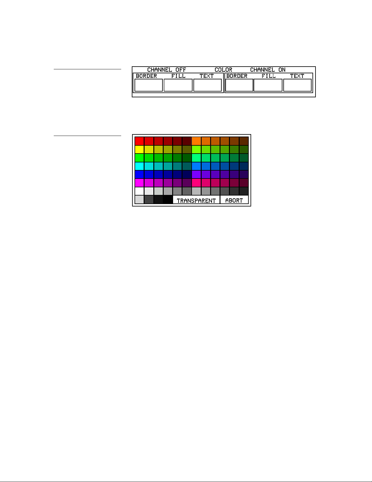
Figure 81
settings box
CHANNEL OFF/ON color
Figure 82
Color palette
2. Press black in the color palette (Figure 82) to set the border color.
3. Press the FILL button in the BARGRAPH PROPERTIES page to re-open the
color options.
4. Press white to set the fill color.
5. Press the TEXT button to re-open the color options.
6. Press red to set the text color.
7. Press EXIT SAVE CHANGE in the VERTICAL BARGRAPH PROPERTIES
page to store the new joystick properties in memory and press EXIT to return to
the current page.
Linking the New Page to the Main Page
Use the ATTRIBUTES page to link buttons to pages. This operation requires
changing the button text and setting a page flip.
1. Press the MAIN PAGE button to flip to the MAIN page.
2. Press EDIT to open the Edit bar.
3. Press BUTTON on the Edit bar to open the BUTTON menu options list as
shown in Figure 83.
Color Active-Matrix LCD Touch Panels Designing a Touch Panel Page 53
Page 62

Figure 83
Message bar
BUTTON menu options
Figure 84
4. Press TEXT/IMAGE to change the MAIN PAGE button text when the message
bar (Figure 84) appears.
Figure 85
TEXT/IMAGE page
5. Press the MAIN button to open the TEXT/IMAGE page shown in Figure 85.
54 Designing a Touch Panel Page Color Active-Matrix LCD Touch Panels
Page 63
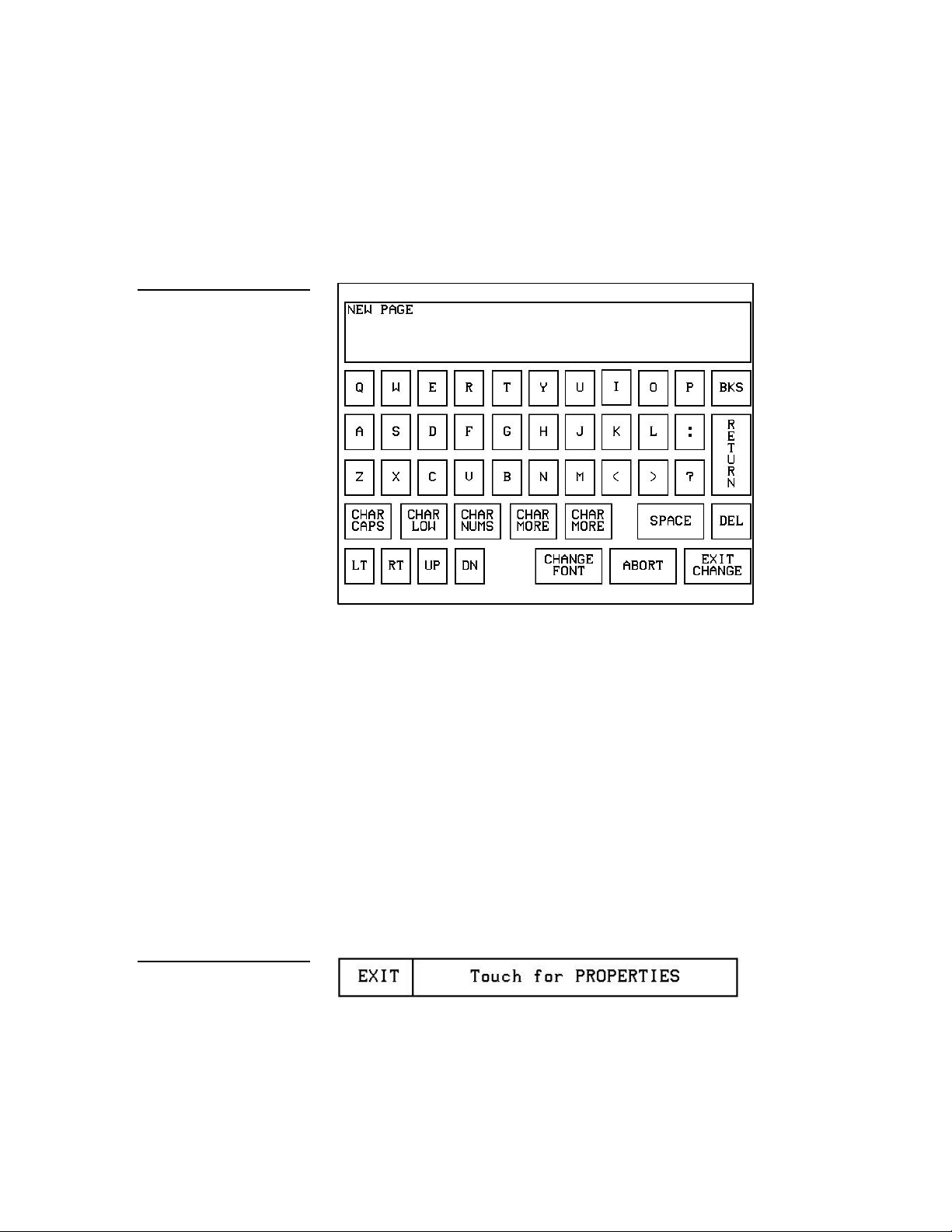
Figure 86
message bar
Keyboard: New Page
6. Press TEXT OFF to open the keyboard.
7. Press DEL four times to delete MAIN.
8. Type NEW PAGE. The text appears in the keyboard window shown in Figure 86.
Figure 87
EDIT PROPERTIES
9. Press EXIT CHANGE to close the keyboard and return to the TEXT/IMAGE
page.
10. Press MAKE ON SAME AS OFF to set the text for the button’s On and Off
states.
11. Press EXIT SAVE CHANGE to close the TEXT/IMAGE page and return to the
MAIN page.
12. Press EDIT to open the Edit bar.
13. Press BUTTON to open the BUTTON OPTION menu.
14. Press PROPERTIES in the BUTTON OPTION menu to open the message bar
shown in Figure 87.
15. Press the NEW PAGE button to open the BUTTON PROPERTIES page.
Color Active-Matrix LCD Touch Panels Designing a Touch Panel Page 55
Page 64

Figure 88
Page FLIP buttons
Figure 89
PAGE FLIP TYPE menu
16. In the BUTTON PROPERTIES page, use the page FLIP boxes (Figure 88) to set
the page flip for the button.
17. Press the left page flip box to open the PAGE FLIP TYPE menu shown in
Figure 89.
18. Press FLIP STANDARD to set the PAGE FLIP TYPE and return to the BUTTON
PROPERTIES page.
19. Press the right page FLIP button to select a destination page (Figure 90).
56 Designing a Touch Panel Page Color Active-Matrix LCD Touch Panels
Page 65

Figure 90
Edit bar
PAGE menu
20. Press NEW PAGE to set the page flip and return to the BUTTON PROPERTIES
page.
21. Press EXIT SAVE CHANGE to save changes, close the BUTTON PROPERTIES
page, and return to the Main page.
Figure 91
22. Press EXIT to close the Edit bar.
Exiting Edit Mode
After you finish designing Touch Panel pages, exit EDIT mode.
1. Press EXIT on the Edit bar (Figure 91) to close the Edit bar.
2. Press SETUP to open the SETUP Page shown in Figure 92.
Color Active-Matrix LCD Touch Panels Designing a Touch Panel Page 57
Page 66

Figure 92
SETUP page
Figure 93
PROTECTED SETUP page
3. Press PROTECTED SETUP to open the PROTECTED SETUP page shown in
Figure 93.
4. Press EDITOR to toggle EDIT mode off.
5. Press EXIT to close the PROTECTED SETUP page and return to the SETUP
page (Figure 92).
6. Press EXIT to close the Setup page and return to the Main page (Figure 95).
58 Designing a Touch Panel Page Color Active-Matrix LCD Touch Panels
Page 67

SETUP
Figure 94
MAIN page
SETUP page flowchart
Touch Panel Program Reference
Overview
You use the SETUP and PROTECTED SETUP pages to configure the Touch Panel
operates. This section contains operation flowcharts, instructions, and menu
option descriptions. The buttons shown in Figure 94 appear when you power up
the Touch Panel.
Setup Page
The flowchart in Figure 95 shows the buttons you press to access the SETUP page.
Figure 95
MAIN
PAGE
From the MAIN page, press the SETUP button to open the SETUP page shown in
Figure 96.
Color Active-Matrix LCD Touch Panels Touch Panel Program Reference 59
Page 68

control systems.
Figure 96
page
BEEP button
section.
SETUP
Optional WIRELESS
SETTINGS button
for WAV-PK and
SMT-PK wireless
Beep
The BEEP button (Figure 97) sets the audible beep duration when you press the
screen.
Figure 97
Note
You can override the beep
value setting using the
'ABEEP' and 'ADBEEP'
Send_Commands described
in the AXCESS Programming
Set the BEEP button on 0 to disable the beep sound. Press the UP and DN buttons
to set beep time in .10-second increments. The minimum beep time setting is 0 and
the maximum is 5 (0.5 second duration).
LCD timer
The LCD TIMER button (Figure 98) sets the length of time the Touch Panel can be
idle before activating screen-saver mode.
60 Touch Panel Program Reference Color Active-Matrix LCD Touch Panels
Page 69

Figure 98
LCD TIMER button
Figure 99
When the Touch Panel goes into screen-saver mode, the LCD is powered-down.
With a setting of 5, the panel goes into screen-saver mode if there is no activity for 5
minutes. Press the UP and DN buttons to change the time that the timer screen
turns on when the Touch Panel is idle. The minimum time setting is 1 and
maximum is 120.
Set time and date
Press SET TIME AND DATE to open the page shown in Figure 99.
SET TIME AND DATE page
Set the year, hour, month, minute, day, second, clock display, and day/month
display.
• • YEAR Press the UP and DN buttons to set the year.
Color Active-Matrix LCD Touch Panels Touch Panel Program Reference 61
Page 70

• • HOUR Press the UP and DN buttons to set the hour.
DOUBLE BEEP button
section.
button examples
• • MONTH Press the UP and DN buttons to set the month.
• • MIN Press the UP and DN buttons to set the minute.
• • DAY Press the UP and DN buttons to set the day.
• • SECOND Press the UP and DN buttons to set the seconds.
• DISPLAY MONTH/DAY, DAY/MONTH Press to set the month and day
display.
• DISPLAY 12:00/24:00 Press to set the clock display to a 12- or 24-hour
format. For example, the 12-hour clock format changes from 12:00 to 1:00,
and the 24-hour clock changes from 12:00 to 13:00.
Double beep
Press the DOUBLE BEEP button (Figure 100) to toggle the double beep option on or
off. The double beep sounds when you press the screen.
Figure 100
Note
You can override the beep
value setting using the
'ABEEP' and 'ADBEEP'
Send_Commands described
in the AXCESS Programming
Figure 101
AXlink, SERIAL #, and vX.XX
Set the BEEP button (described earlier) to 0 to disable the double-beep sound.
AXlink, serial number, and vX.XX
The AXlink, SERIAL #, and vX.XX buttons shown in Figure 101 are information
buttons (display only).
The AXlink button is an AXCESS communication indicator that blinks once every
second when the AXCESS Central Controller is connected to the Touch Panel. The
62 Touch Panel Program Reference Color Active-Matrix LCD Touch Panels
Page 71

Figure 102
SET BRIGHTNESS page
SERIAL NUMBER button shows the serial number for the Touch Panel, and the
vX.XX button shows the current firmware version installed in the Touch Panel.
Set brightness
Press SET BRIGHTNESS in the SETUP page to open the page shown in Figure 102.
Press the UP and DN buttons to set the LCD brightness on the Touch Panel. The
minimum brightness level is 1 and the maximum is 8. The TRANSPARENT and
ABORT buttons are disabled on this page.
Protected Setup
The PROTECTED SETUP button opens the PROTECTED SETUP page where you
set Touch Panel passwords, mouse controls, communications parameters, etc.
Because there are so many operations associated with PROTECTED SETUP page,
they are described in the Protected Setup subsection.
Show palette
Press SHOW PALETTE in the SETUP page to open the page. This page shows the
color selections available with the Touch Panel.
Color Active-Matrix LCD Touch Panels Touch Panel Program Reference 63
Page 72
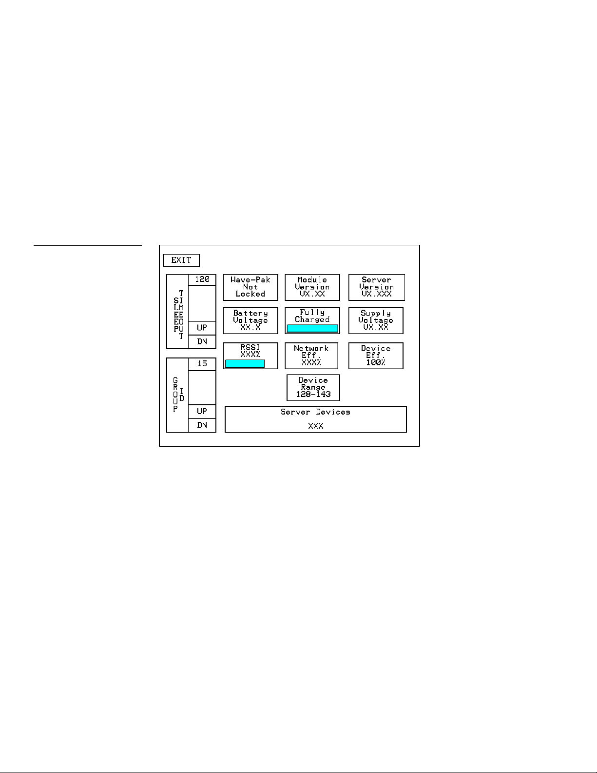
Figure 103
WAV-PK page
Wireless settings (optional WAV-PKM)
The WIRELESS SETTINGS button appears on the SETUP page when a WAV-PK
WavePack is connected to the Touch Panel. The WAV-PK provides wireless twoway RF spread-spectrum Touch Panel control and contains a lead-acid
rechargeable battery that supplies independent power to the panel. Refer to the
AXR-WAVES Server, WaveLink, Wireless Power Packs, Power Module AXR-WAVES
WAV-CHG instruction manual for detailed setup information Press the WIRELESS
SETTINGS button to open the optional page shown in Figure 103.
The Wave-Pack page shows the following information:
• SLEEP TIMEOUT Press the UP and DN buttons to set the sleep time. The
minimum sleep time is 0 (off) and maximum is 120 minutes. When the Touch
Panel goes to sleep, all communication and battery discharge stops. If the
sleep time is set to 5, the panel goes into sleep mode if there is no activity for
5 minutes. The Touch Panel automatically wakes up when you touch the
screen for more than .5 seconds.
• GROUP ID Sets the group ID number on the Touch Panel to communicate
with the wireless AXR-WAVES with the same group ID number. The group
ID range is 0–15. The group ID setting overrides the DIP switch setting on
the WAV-PK.
64 Touch Panel Program Reference Color Active-Matrix LCD Touch Panels
Page 73

• Wave-Pak Not Locked/Locked Appears when an optional WAV-PK is
connected to the Touch Panel. Not locked indicates the Touch Panel is not
communicating with the AXR-WAVES. Locked indicates the Touch Panel is
locked on (communicating) to the AXR-WAVES connected to the control
system.
• Battery Voltage XX.X Shows the voltage level of the lead-acid
rechargeable battery in the WAV-PK.
• Device Range Shows the device range that your server can recognize.
Devices outside that range will not be recognized
• • Server Devices XXX Shows the group address on the AXR-WAVES
communicating with the Touch Panel.
• Module Version VX.XX Shows the firmware version installed in the
WAV-PK.
• • Fully Charged/Not Charging / Charging Fully Charged appears when
the battery in the WAV-PK is fully charged. Not Charging appears when the
lead-acid battery is not charging. Charging appears when the lead-acid
battery is charging. The shaded area in the horizontal gauge button moves
from left to right as the battery voltage level increases.
• • RSSI XXX% Shows the strength of the AXR-WAVES signal received by the
Touch Panel. The signal strength fluctuates between 50% and 100%.
• Server Version Shows the firmware version installed in the AXR-
WAVES.
• • Supply Voltage VX.XX Shows the voltage level of the external power
supply (optional) connected to the WAV-PK.
• Device Eff. XXX% Shows the strength of the AXR-WAVES signal
received by the Touch Panel. The shaded area in the horizontal gauge moves
from left-to-right as the RF signal intensity increases. The shaded area
fluctuates between 50% and 100%.
Color Active-Matrix LCD Touch Panels Touch Panel Program Reference 65
Page 74

Figure 104
SMT-PK page
• Network Eff. XXX% Shows the communication efficiency of bi-directional
RF transmissions between the Touch Panel and AXR-WAVES. The efficiency
percentage (0–100%) is determined by the number of retries required to
complete a panel operation.
Wireless settings (optional SMT-PK)
The WIRELESS SETTINGS button appears on the SETUP page when a SMT-PK
SmartPack is connected to the Min-Touch. Press the WIRELESS SETTINGS button
to open the optional page shown in Figure 104.
Refer to the SmartPacks for TiltScreen Touch Panels instruction manual for detailed
information.
• SLEEP TIMEOUT Press the UP and DN buttons to set the sleep time. The
minimum sleep time is 0 (off) and maximum is 120 minutes. When the panel
goes to sleep, all communication and battery discharge stops. If the sleep
time is set to 5, the panel goes into sleep mode if there is no activity for 5
minutes. The panel wakes up when you touch the screen for more than .5
seconds.
• Smart-Pk Module Not Locked/Locked Appears when an optional
SMT-PK is connected to the panel. Not locked indicates the panel is not
66 Touch Panel Program Reference Color Active-Matrix LCD Touch Panels
Page 75

communicating with the AXR-RF RF Receiver. Locked indicates the panel is
BUTTON
BUTTON
1988
PROTECTED SETUP page.
locked on to the AXR-RF connected to the control system.
• Battery Voltage XX.X Shows the voltage level of the lead-acid
rechargeable battery in the SMT-PK.
• AMX RF ON/OFF Toggles RF transmission on or off.
• Module Version VX.XX Shows the firmware version installed in the
SMT-PK.
• Fully Charged/Not Charging/Charging Fully Charged appears when
the battery in the SMT-PK is fully charged. Not Charging appears when the
lead-acid battery is not charging. Charging appears when the lead-acid
battery is charging. The shaded area in the horizontal gauge moves from left
to right as the battery voltage level increases.
• AMX IR 38 kHz/455 kHz/OFF Toggles the IR transmitting frequency to
38 kHz, 455 kHz, or OFF.
Figure 105
PROTECTED SETUP page
flowchart
Note
When the Edit bar is enabled,
you do not have to enter the
password when opening the
• Supply Voltage VX.XX Shows the voltage level of the external power
supply (optional) connected to the SMT-PK.
Protected Setup Page
The PROTECTED SETUP page allows you to set passwords, mouse controls, and
communications parameters. The flowchart in Figure 105 shows how to access the
PROTECTED SETUP page, which is password-protected. When you press the
PROTECTED SETUP button on the SETUP page, a number keypad appears.
MAIN
PAGE
SETUP
PROTECTED SETUP
TYPE
Type 1988, which is the system default password, and press ENTER to open the
PROTECTED SETUP page. (You can change the password, as explained in the
Setup password subsection.) If you enter a wrong number, press CLEAR and re-enter
the number. The PROTECTED SETUP page (Figure 106) appears when you enter
the correct number.
Color Active-Matrix LCD Touch Panels Touch Panel Program Reference 67
Page 76

Figure 106
PROTECTED SETUP page
BAUD button
Baud
The BAUD button (Figure 107) sets the baud rate through a factory installed port at
the rear of the Touch Panel. The baud rate is automatically set to 1,200 when you
activate the MOUSE button. The RS-232 communication automatically defaults to
the factory preset baud if you disable the MOUSE ON button.
Figure 107
Note
Make sure to match the baud
transmission rate for the
external RS-232 device.
• BAUD Press the UP and DN buttons to set the data communication speed
through a factory installed port on the Touch Panel. Available baud rates are
300, 600, 1200, 2400, 4800, 9600, 19.2, and 38.4.
Device base
Press the DEVICE BASE button to open the keypad (Figure 108) and set the base
address for the Touch Panel. The base address range is 1–255.
68 Touch Panel Program Reference Color Active-Matrix LCD Touch Panels
Page 77
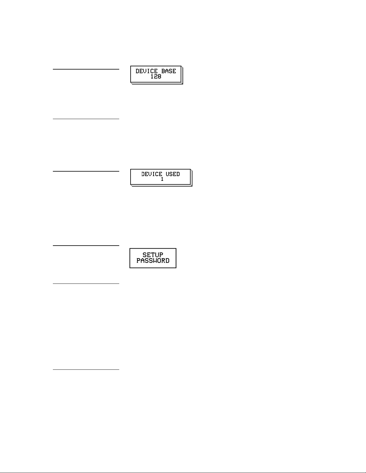
Figure 108
DEVICE BASE button
130, and 131 consecutively.
DEVICE USED button
password.
when mouse control is active.
Device used
Note
If four devices are used, and
the base address is 128, then
the touch panel will use
device numbers 128, 129,
Figure 109
Figure 110
SETUP PASSWORD button
Warning
If you change the password
number, record the new
number and keep it in a
secure place. If you change
the password, AMX cannot
provide you with the
Press the DEVICE USED button to open the keypad (Figure 109) and set the panel’s
device number from 1 – 4. Each device number supports up to 255 channel code
button assignments. The multiple device setting option allows you to create up to
four unique Touch Panel buttons and/or pages.
Setup password
Press the SETUP PASSWORD button to open the keypad shown in Figure 110 and
set the numeric SETUP page password.
The password number range is 1 through 9,999. (Do not use zero.) Do not change
the SETUP page password unless you are concerned about unauthorized access to
the Touch Panel pages.
• CLEAR Press to clear the number in the keypad display.
• ENTER Press to enter the new password into Touch Panel memory and
close the keypad.
Note
You can still control the
Touch Panel with your finger
Color Active-Matrix LCD Touch Panels Touch Panel Program Reference 69
Mouse button
Press the MOUSE button (Figure 111) to open the Mouse Setup page shown in
Figure 112.
Page 78

Figure 111
MOUSE button
Figure 112
MOUSE SETUP page
• MOUSE SPEED Press the UP and DN buttons to set the mouse pointer
speed. The minimum (slowest) speed is 1 and the maximum (fastest) is 10.
• • MOUSE ACTIVE Press to activate the mouse pointer. The active mouse
pointer appears in the top-left corner of the LCD.
Power up page
Press the POWER UP PAGE button to open the POWER UP page list (Figure 113).
70 Touch Panel Program Reference Color Active-Matrix LCD Touch Panels
Page 79

Figure 113
and list
WAKE UP MESSAGE button
POWER UP PAGE button
Select a page to designate the first page to appear when you power up the Touch
Panel. Select NONE to disable this option. If none is selected, the POWER UP page
will be the last active page the next time the touch panel is used.
Wake up message
Press WAKE UP MESSAGE (Figure 114) to open the Touch Panel keyboard, and
enter an ASCII string to be sent to the AXCESS Central Controller when the Touch
Panel wakes up. You can program the control system to perform specific
operations when the message is received. Refer to the AXCESS Programming section
for detailed programming information.
Figure 114
Auto assign
Press AUTO ASSIGN (Figure 115) to enable the automatic channel assignment
option. This option sets the Touch Panel to prompt you to manually or
automatically assign a channel number (1 – 255) to a new button. If you select this
option, the Touch Panel assigns the lowest unused channel to the button. Press the
AUTO ASSIGN again to disable this option.
Color Active-Matrix LCD Touch Panels Touch Panel Program Reference 71
Page 80

Figure 115
AUTO ASSIGN button
PAGE PASSWORD button
mode.
screen.
Figure 116
Page password
Press the PAGE PASSWORD button (Figure 116) to open the keypad and assign a
numeric page password to a specific page.
If you try to open a password-protected page, the keypad appears, and you must
enter the correct password number to open the new page. The page password
range is 1 – 9,999.
• • CLEAR Clears the number in the keypad display.
• • ENTER Sets the page password number, closes the keypad, and returns to
the PROTECTED SETUP page.
Note
Press and hold for 2 seconds
to enter the Test Calibration
Figure 117
CALIBRATE decision button
Note
The crosshair for calibration
is first shown at the top-left
corner of the Touch Panel
Calibrate
Press CALIBRATE to open the decision button shown in Figure 117, and reset the
vertical and horizontal touch points on the LCD.
• YES Starts the calibration process. Carefully press each crosshair that
appears using your finger or dull pointer. When the calibration process is
complete, press the screen to return to the PROTECTED SETUP page.
• NO Cancels the calibration process.
72 Touch Panel Program Reference Color Active-Matrix LCD Touch Panels
Page 81

Figure 118
panel memory.
POWER UP MESSAGE
button
Figure 119
Power up message
Press POWER UP MESSAGE (Figure 118) to open the keyboard, and enter an ASCII
string to be sent to the AXCESS Central Controller when the Touch Panel is
powered up. The control system can be programmed to perform specific operations
when the message is received. Refer to the AXCESS Programming section for
detailed programming information.
System page
Press the SYSTEM PAGE button (Figure 119) to open the SYSTEM page
(Figure 120).
SYSTEM PAGE button
Figure 120
SYSTEM page
Warning
The System page should only
be used to purge unwanted
buttons, bitmaps, icons,
fonts, and stored Touch
Panel settings. Before using
this page, make sure you
have a backup copy of the
Touch Panel program stored
in the TPDesign 3 software
program. If you press YES on
any of the DELETE buttons,
the stored data is
permanently erased from the
Color Active-Matrix LCD Touch Panels Touch Panel Program Reference 73
Page 82

Figure 121
decision button
DELETE ALL BUTTONS
decision button
Figure 122
DELETE ALL BITMAPS
decision button
• DELETE ALL BUTTONS Opens the decision button shown in Figure 121.
Press YES to clear all Touch Panel buttons or NO to cancel the operation.
• BUTTON MEM FREE Shows the memory available to store buttons in
1,024-byte increments.
• DELETE ALL BITMAPS Opens the decision button shown in Figure 122.
Press YES to clear all the bitmaps or NO to cancel the operation.
Figure 123
DELETE ALL ICONS
decision button
Figure 124
DELETE ALL FONTS
• DELETE ALL ICONS Opens the decision button shown in Figure 123.
Press YES to clear all the icons or NO to cancel the operation.
• DELETE ALL FONTS Opens the decision button shown in Figure 124.
Press YES to clear all the fonts or NO to cancel the operation.
74 Touch Panel Program Reference Color Active-Matrix LCD Touch Panels
Page 83

Figure 125
BITMAPS menu
• SHOW BITMAPS ID'S Opens the BITMAPS menu (Figure 125) which
shows you a listing of the available bitmaps.
• SHOW ICONS ID'S Opens the ICONS menu (Figure 126) which shows
you a listing of the available icons.
Figure 126
ICONS menu
— MORE Forwards the menu listing by providing further options.
— ABORT Cancels the menu process and returns to the current page.
Color Active-Matrix LCD Touch Panels Touch Panel Program Reference 75
Page 84

and Bodini 18.
Figure 127
is erased.
button
FONTS menu
Note
You can use the TPDesign 3
software program to import
variable fonts into the panel.
Custom fonts include Arial 12
Warning
You should only use the
FACTORY RESET button to
erase all stored data in the
Touch Panel. The data
cannot be recovered after it
• SHOW FONTS ID'S Opens the FONTS menu (Figure 127) which shows
you a listing of the available fonts.
• FACTORY RESET Opens the decision button shown in Figure 128. Press
YES to clear all Touch Panel memory or NO to cancel the operation.
Figure 128
CLEAR MEMORY decision
Figure 129
EDITOR button
Editor
Press EDITOR (Figure 129) in PROTECTED SETUP page to activate the EDIT
button. The PROTECTED SETUP page remains open until you press EXIT
When you exit the PROTECTED SETUP page, the EDIT button (Figure 130)
appears on the top or bottom of the LCD. You can press the EDIT button to open
76 Touch Panel Program Reference Color Active-Matrix LCD Touch Panels
Page 85

Figure 130
PAGE TRACKING button
SLEEP MESSAGE button
EDIT button
Figure 131
Edit bar
the Edit bar (Figure 131) and create buttons, pages, popup pages, and set a wide
variety of Touch Panel settings. The active Touch Panel page name also appears in
the active Edit bar. For example, the Edit bar sample in Figure 131 shows the
current page name is MAIN PAGE. Because there are so many operations
associated with the EDIT button, they are described in the Edit button subsection.
Page tracking
Press PAGE TRACKING (Figure 132) to toggle the page tracking option ON or OFF.
When page tracking is enabled, the Touch Panel sends page data back to the
control system depending on how you set the Touch Panel. Page tracking data can
be used to control pages in multiple Touch Panels.
Figure 132
Figure 133
Sleep message
Press SLEEP MESSAGE (Figure 133) to open the Touch Panel keyboard and enter a
message that will appear on-screen when the Touch Panel goes into sleep-saver
mode. Refer to LCD timer to set the Touch Panel’s screen-saver mode.
Color Active-Matrix LCD Touch Panels Touch Panel Program Reference 77
Page 86

Button
Slider
PAGE
SETUP
BUTTON
BUTTON
1988
BUTTON
Figure 134
flowchart
FUNCTION SHOW button
Function show
Press FUNCTION SHOW (Figure 134) to display channel code numbers and
variable text code numbers on Touch Panel buttons, joysticks, sliders, and
bargraphs. As shown in Figure 135, a channel code number appears in the upperleft corner of the button, and a variable text number appears in the lower-right
corner.
1. Press EXIT twice to return to the MAIN page. If nothing appears in the button,
it does not have a channel code or variable text code assignment.
2. Press FUNCTION SHOW again to disable the channel code and variable text
code numbers.
Figure 135
Function show button and
slider example
Figure 136
Edit button activation
0
132132
LIGHT
PANEL
255255
255
Edit button
Press EDITOR in the Protected Setup page to enable the Edit button. The Protected
Setup page remains open until you press EXIT. Then, the Edit button appears on
every page. The flowchart in Figure 136 shows the sequence to activate the Edit
button.
MAIN
EXIT
SETUP
EXIT
PROTECTED
TYPE
EDITOR
78 Touch Panel Program Reference Color Active-Matrix LCD Touch Panels
Page 87

Edit bar
Figure 137
page
Edit bar
Enabled EDITOR button in
the PROTECTED SETUP
Press EXIT in the PROTECTED SETUP page (Figure 137) to return to the MAIN
page.
Press EDITOR to activate the Edit bar shown in Figure 138. When the Edit bar is
enabled, it appears on the top or bottom of each Touch Panel page.
Figure 138
Color Active-Matrix LCD Touch Panels Touch Panel Program Reference 79
Page 88

Figure 139
imported to the Touch Panel.
ADD BUTTON message
Edit Bar — BUTTON menu options
Note
Buttons with Unicode Fonts
can only be created and
edited within TPDesign 3 then
Edit Bar — Button Menu Options
Press EDIT and BUTTON to open the menu shown in Figure 139.
You can use the BUTTON menu to create, configure, and revise Touch Panel
button settings. The Touch Panel can however use the other BUTTON menu
features on them. The Edit bar also shows the current page name. The Edit bar also
shows the current page name. The Edit bar in Figure 139 shows MAIN PAGE is the
current page.
Add
Press ADD to add a button when the ADD BUTTON message (Figure 140) appears
on the LCD. The first touch point is the upper-left corner of the button.
Figure 140
Drag your finger horizontally across the screen and down to set the height and
width of the button. When the new button appears on the page, the message bar
shows you the X/Y page-position coordinates and the X/Y resolution size.
80 Touch Panel Program Reference Color Active-Matrix LCD Touch Panels
Page 89

Note
options.
COPY BUTTON message
MOVE BUTTON message
RESIZE BUTTON message
You can adjust the button
position with the MOVE and
RESIZE
Figure 141
Press the EXIT button in the Edit bar to exit. Use the PROPERTIES option to set the
button color, border style, and configuration settings.
Copy image
Press COPY IMAGE to copy a button when the COPY BUTTON message (Figure
141) appears on the LCD.
Touch the target button and drag the new button to another position. When you
start dragging the new button, the message bar shows you the current X/Y pageposition coordinates, and the X/Y resolution size. Press EXIT on the Edit bar to
exit.
Move
Press MOVE to move a button when the MOVE BUTTON message (Figure 142)
appears on the LCD. Then, drag the button to the new position. When you start
moving the button, the message bar shows you the current X/Y page-position
coordinates and the X/Y resolution size. Press EXIT in the message bar to exit.
Figure 142
Resize
Press RESIZE to resize a button when the RESIZE BUTTON message (Figure 143)
appears on the LCD.
Figure 143
Color Active-Matrix LCD Touch Panels Touch Panel Program Reference 81
Page 90

Figure 144
DELETE BUTTON message
Drag your finger horizontally across the screen and down to resize the height and
width of the button.
Press EXIT in the message bar to exit. When you resize the button, the message bar
shows you the current X/Y page-position coordinates, and the X/Y resolution
size. If you add text to a button, the button size must be large enough to
accommodate the text string.
Delete
Press DELETE to delete a button when the DELETE BUTTON message (Figure 144)
appears on the LCD.
Then, choose the button you want to delete to open the decision box shown in
Figure 145.
Figure 145
DELETE button decision box
• YES Deletes the button and returns to the current page.
• NO Cancels the deletion process and returns to the current page.
Text/Image
Press TEXT/IMAGE and a button to open the TEXT/IMAGE page shown in
Figure 146. This option allows you to set the text, icons, and bitmap files for the
current button.
82 Touch Panel Program Reference Color Active-Matrix LCD Touch Panels
Page 91
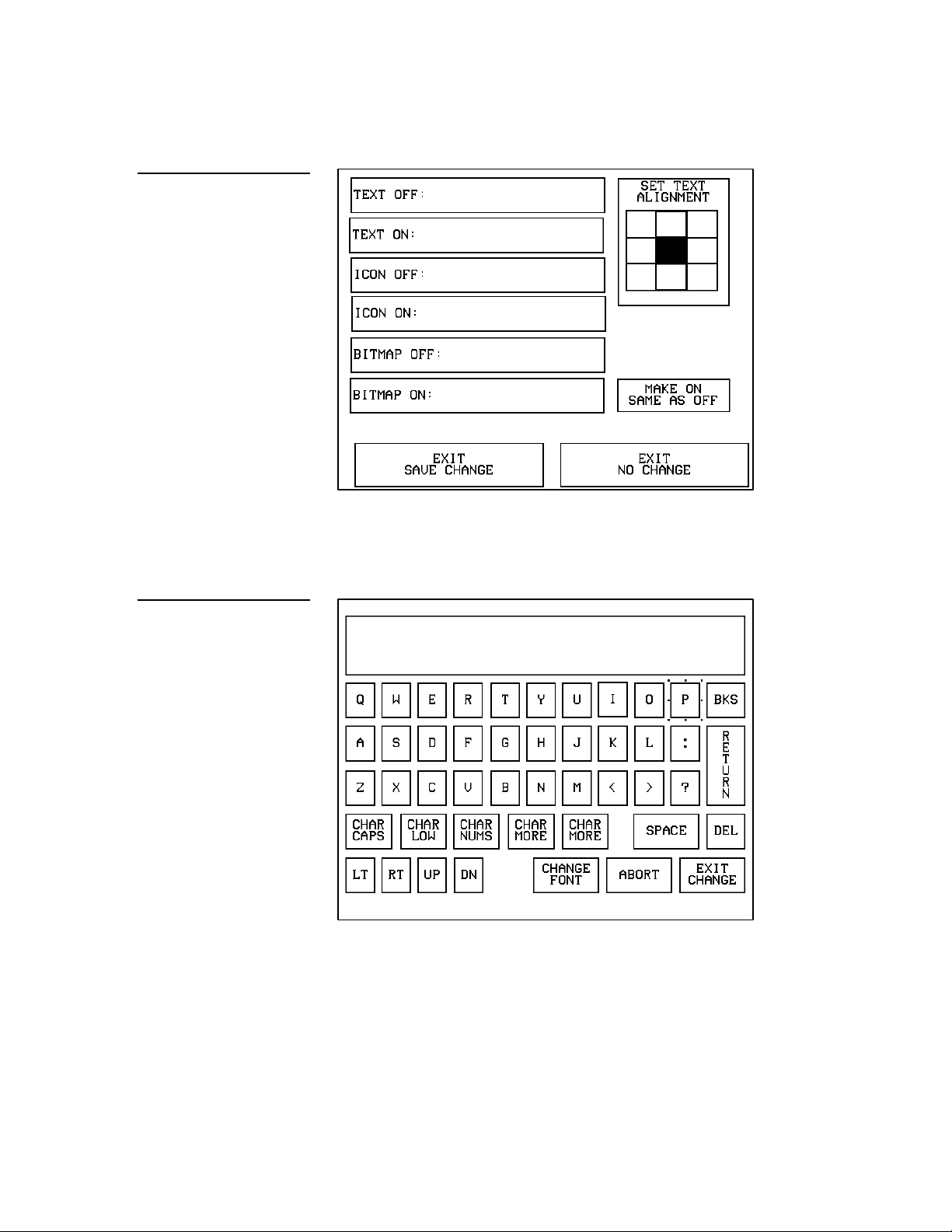
Figure 146
TEXT/IMAGE page
Figure 147
• TEXT OFF Opens the keyboard (Figure 147) where you enter the text to
appear on the OFF-state button.
Keyboard
The text appears in the window at the top of the keyboard. If the text string
exceeds the space in the button, the Touch Panel generates an error message.
Change the size of the button or reduce the font size to clear the error
message.
Color Active-Matrix LCD Touch Panels Touch Panel Program Reference 83
Page 92

Bodini 18.
Figure 148
FONTS menu
Note
— CHAR CAPS Sets the keyboard to uppercase characters.
— CHAR LOW Sets the keyboard to lowercase characters.
— CHAR NUMS Sets the keyboard to numeric characters.
— CHAR MORE Toggles the keypad to special characters.
— SPACE Enters a blank space.
— DEL Deletes a space or character where the flashing cursor appears.
— LT, RT, UP, DN Moves the flashing cursor position left, right, up, and
down.
— CHANGE FONT Opens the FONTS menu (Figure 148) where you select
the text font (typeface) for the button.
You can use the TPDesign 3
software program to import
variable fonts into the panel.
Custom fonts are Arial 12 and
— ABORT Closes the FONTS menu and returns to the Text/Image page.
— EXIT CHANGE Saves current settings, closes the keyboard, and returns
to the TEXT/IMAGE page.
• TEXT ON Opens the keyboard (Figure 147) where you enter the text to
appear on the ON-state button.
84 Touch Panel Program Reference Color Active-Matrix LCD Touch Panels
Page 93

Figure 149
ICONS menu
• ICON OFF Opens the ICONS menu (Figure 149) where you select an icon
to appear on the Off-state button. Select MORE to view more icons or ABORT
to exit and return to the TEXT/IMAGE page.
• ICON ON Opens the ICONS menu (Figure 149) where you select the icon
to appear on the On-state button. Select MORE to view more icon files, and
the ABORT button to exit and return to the TEXT/IMAGE page.
• BITMAP OFF Opens the BITMAPS menu (Figure 150) where you select
the bitmap to appear on the Off-state button. Select MORE to view more icon
files, and the ABORT button to exit and return to the TEXT/IMAGE page.
• BITMAP ON Opens the BITMAPS menu (Figure 150) where you select the
bitmap to appear on the On-state button. Select MORE to view more icon
files, and the ABORT button to exit and return to the TEXT/IMAGE page.
Color Active-Matrix LCD Touch Panels Touch Panel Program Reference 85
Page 94

Figure 150
Bitmaps menu
Figure 151
• SET TEXT ALIGNMENT Sets the text alignment on the button. Figure 151
shows the alignment option textually for each button. The text references do
not appear on the actual SET TEXT ALIGNMENT buttons.
SET TEXT ALIGNMENT
options
• MAKE ON SAME AS OFF Copies the OFF-state text, icon, and/or bitmap
settings to the ON-state buttons.
• EXIT SAVE CHANGE Saves the current settings, exits the TEXT/IMAGE
page, and returns to the current page.
• EXIT NO CHANGE Cancels the current settings and returns to the current
page.
86 Touch Panel Program Reference Color Active-Matrix LCD Touch Panels
Page 95

Figure 152
PROPERTIES page
Properties
Select PROPERTIES and a button to open the PROPERTIES page (Figure 152).
Then, you can set the border style, channel/variable text device and channel
numbers, button type, button options, flip type, string, and channel OFF/ON state
attributes.
Figure 153
Border menu
• BORDER Opens the BUTTON BORDER menu (Figure 153) where you
select the border style. Figure 154 shows the border names and styles.
Color Active-Matrix LCD Touch Panels Touch Panel Program Reference 87
Page 96

Figure 154
Border name and style
Border names and styles
Name Style Name Style
No border
Single raised
No border special Double raised
Single line Triple raised
Double line Double line 2
Triple line Double line 3
Single rounded 3D neon blue
Double rounded 3D neon green
Single diamond 3D round 1
Double diamond 3D round 2
Double shadow
3D neon 1
3D rectangle 1 3D neon 2
3D rectangle 2
88 Touch Panel Program Reference Color Active-Matrix LCD Touch Panels
Page 97

• CHANNEL DEV: Opens the keypad where you set the device number for
the current button or Touch Panel page. The device range is 1–4.
• CHANNEL CHAN: Opens the keypad where you set the channel code for
the current button. The channel code range is 1–255. Record the channel
code settings if you want to create duplicate buttons and functions on
another page. If the AUTO ASSIGN option is enabled in the PROTECTED
SETUP page, the Touch Panel prompts you to automatically or manually
assign the channel code. Select YES to allow the Touch Panel to assign the
lowest available channel number.
• VAR TEXT DEV: Opens the keypad where you set the device number for
the current button and Touch Panel page. The device range is 1–4.
• VAR TEXT CHAN: Opens the keypad where you set the variable text
channel code for the current button. The channel code range is 1–255.
Record the channel code settings if you want to create duplicate buttons and
their functions on another page. If the AUTO ASSIGN option is enabled in
the PROTECTED SETUP page, the Touch Panel prompts you to
automatically or manually assign the channel code. Select YES to allow the
Touch Panel to automatically assign the lowest available channel number.
• BUTTON TYPE Opens the BUTTON TYPE menu (Figure 155) where you
select the button type. After you select a button type, the PROPERTIES page
resets with specific options according to that button type. For example, if you
select the button type GENERAL, the BUTTON OPTIONS, FLIP, and
STRING options appear in the PROPERTIES page.
Color Active-Matrix LCD Touch Panels Touch Panel Program Reference 89
Page 98

Figure 155
BUTTON TYPE menu
— GENERAL Sets the button to automatically send a message to the
AXCESS Central Controller via the AXlink connector, PC via the factory
installed port connector, or with WAVE wireless communication. Refer to
Properties Page— Button Type: General in this section for more information.
— JOYSTICK Sets the button to a joystick that includes a control stick.
When you move the control stick, the Touch Panel sends feedback (data) to
the control system and to the external device to perform a pre-programmed
operation. Refer to Properties Page— Button Type: Joystick in this section for
more information.
— VERTICAL BARGRAPH Sets the button to a vertical bargraph or slider.
Feedback for bargraph or slider response comes from the control system.
Refer to Properties Page— Button Type: Vertical Bargraph in this section for
detailed information.
— HORIZONTAL BARGRAPH Sets the button to a horizontal bargraph or
slider. Feedback for bargraph or slider response comes from the control
system. Refer to Properties Page— Button Type: Horizontal Bargraph in this
section for detailed information.
— BRIGHTNESS Sets the button to open the Brightness page shown in
Figure 156. The Brightness page allows you to set the Touch Panel’s LCD
light level. The minimum brightness setting is 1 and the maximum is 8.
90 Touch Panel Program Reference Color Active-Matrix LCD Touch Panels
Page 99

Figure 156
BRIGHTNESS page
— TIME Sets the button to open the TIME/DATE page shown in
Figure 157. Refer to Set time and date described in this section for more
information.
— DATE Sets the button to open the TIME/DATE page shown in
Figure 157. Refer to Set time and date described in this section for more
information.
Figure 157
TIME/DATE page
Color Active-Matrix LCD Touch Panels Touch Panel Program Reference 91
Page 100

Figure 158
Keypad
— KEYPAD Sets the button to open the keypad (Figure 158) so you can
enter a password or value assignment. All the keypad buttons are
interactive except for the entry display.
— KEYBOARD Sets the button to open the keyboard so you can enter a
name or string. All the keyboard buttons are interactive except for the
message box as seen in Figure 160.
Figure 159
Keyboard
— SETUP Sets the button to open the SETUP page shown in Figure 160.
Refer to Setup Page in this section for more information.
92 Touch Panel Program Reference Color Active-Matrix LCD Touch Panels
 Loading...