

Page 1
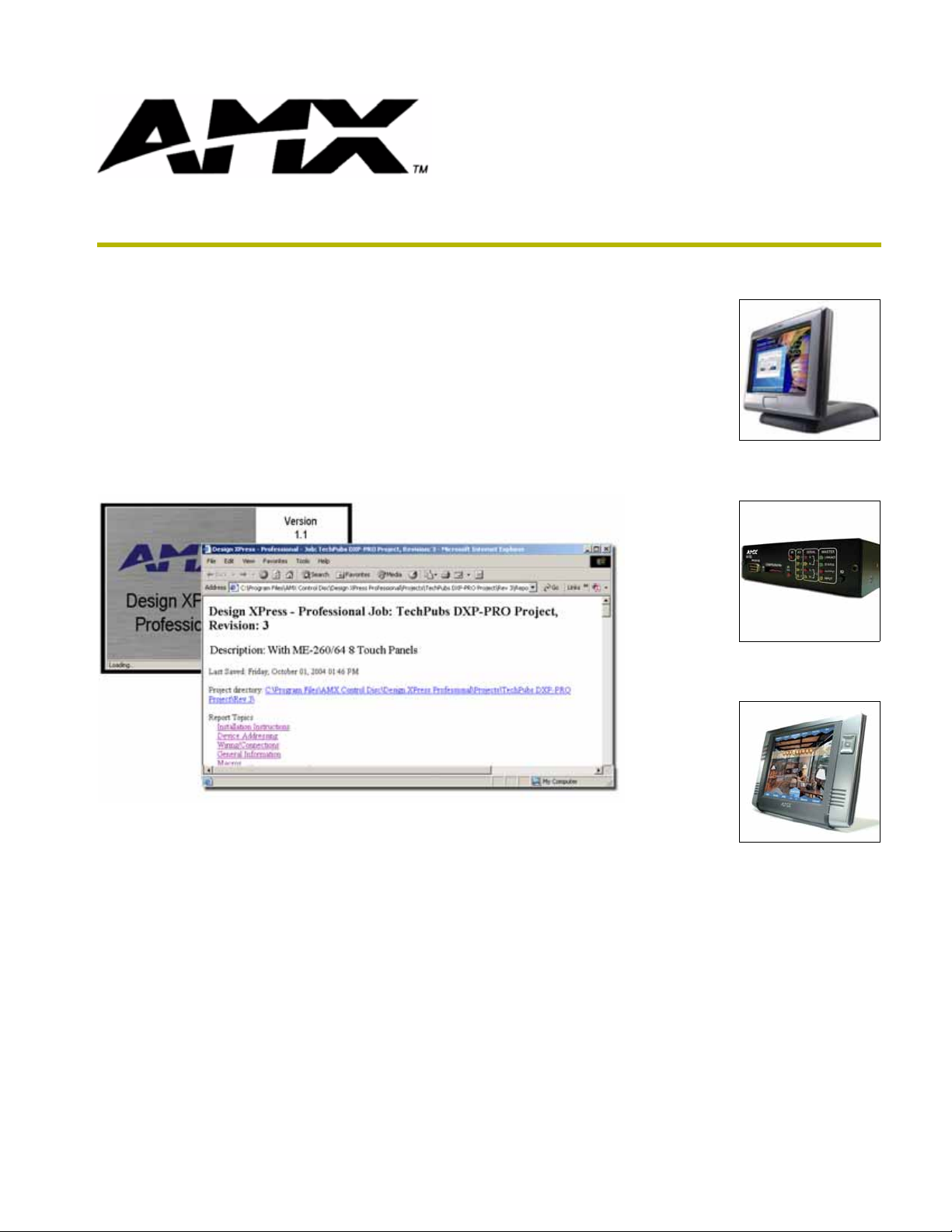
Design XPress Professional
version 1.1
instruction manual
On-Site Installer’s Guide
Software
Page 2

Software License and Warranty Agreement
LICENSE GRANT.
AMX grants to Licensee the non-exclusive right to use the AMX Software in the manner described in this License. The AMX Software
is licensed, not sold. The AMX Software consists of generally available programming and development software, product
documentation, sample applications, tools and utilities, and miscellaneous technical information. Please refer to the README.TXT
file on the compact disc or download for further information regarding the components of the AMX Software. The AMX Software is
subject to restrictions on distribution described in this License Agreement. YOU MAY NOT LICENSE, RENT, OR LEASE THE AMX
SOFTWARE. You may not reverse engineer, decompile, or disassemble the AMX Software.
INTELLECTUAL PROPERTY.
The AMX Software is owned by AMX and is protected by United States copyright laws, patent laws, international treaty provisions,
and/or state of Texas trade secret laws. Licensee may make copies of the AMX Software solely for backup or archival purposes.
Licensee may not copy the written materials accompanying the AMX Software.
TERMINATION. AMX RESERVES THE RIGHT, IN ITS SOLE DISCRETION, TO TERMINATE THIS LICENSE FOR
ANY REASON AND UPON WRITTEN NOTICE TO LICENSEE.
In the event that AMX terminates this License, the Licensee shall return or destroy all originals and copies of the AMX Software to
AMX and certify in writing that all originals and copies have been returned or destroyed.
PRE-RELEASE CODE.
Portions of the AMX Software may, from time to time, as identified in the AMX Software, include PRE-RELEASE CODE and such
code may not be at the level of performance, compatibility and functionality of the final code. The PRE-RELEASE CODE may not
operate correctly and may be substantially modified prior to final release or certain features may not be generally released. AMX is
not obligated to make or support any PRE-RELEASE CODE. ALL PRE-RELEASE CODE IS PROVIDED "AS IS" WITH NO
WARRANTIES.
LIMITED WARRANTY.
AMX warrants that the AMX Software will perform substantially in accordance with the accompanying written materials for a period of
ninety (90) days from the date of receipt. AMX DISCLAIMS ALL OTHER WARRANTIES, EITHER EXPRESS OR IMPLIED,
INCLUDING, BUT NOT LIMITED TO IMPLIED WARRANTIES OF MERCHANTABILITY AND FITNESS FOR A PARTICULAR
PURPOSE, WITH REGARD TO THE AMX SOFTWARE. THIS LIMITED WARRANTY GIVES YOU SPECIFIC LEGAL RIGHTS.
Any supplements or updates to the AMX SOFTWARE, including without limitation, any (if any) service packs or hot fixes provided to
you after the expiration of the ninety (90) day Limited Warranty period are not covered by any warranty or condition, express, implied
or statutory.
LICENSEE REMEDIES.
AMX's entire liability and your exclusive remedy shall be repair or replacement of the AMX Software that does not meet AMX's
Limited Warranty and which is returned to AMX. This Limited Warranty is void if failure of the AMX Software has resulted from
accident, abuse, or misapplication. Any replacement AMX Software will be warranted for the remainder of the original warranty period
or thirty (30) days, whichever is longer. Outside the United States, these remedies may not available.
NO LIABILITY FOR CONSEQUENTIAL DAMAGES. IN NO EVENT SHALL AMX BE LIABLE FOR ANY DAMAGES
WHATSOEVER (INCLUDING, WITHOUT LIMITATION, DAMAGES FOR LOSS OF BUSINESS PROFITS, BUSINESS
INTERRUPTION, LOSS OF BUSINESS INFORMATION, OR ANY OTHER PECUNIARY LOSS) ARISING OUT OF THE USE OF OR
INABILITY TO USE THIS AMX SOFTWARE, EVEN IF AMX HAS BEEN ADVISED OF THE POSSIBILITY OF SUCH DAMAGES.
BECAUSE SOME STATES/COUNTRIES DO NOT ALLOW THE EXCLUSION OR LIMITATION OF LIABILITY FOR
CONSEQUENTIAL OR INCIDENTAL DAMAGES, THE ABOVE LIMITATION MAY NOT APPLY TO YOU.
U.S. GOVERNMENT RESTRICTED RIGHTS. The AMX Software is provided with RESTRICTED RIGHTS. Use, duplication, or
disclosure by the Government is subject to restrictions as set forth in subparagraph (c)(1)(ii) of The Rights in Technical Data and
Computer Software clause at DFARS 252.227-7013 or subparagraphs (c)(1) and (2) of the Commercial Computer Software
Restricted Rights at 48 CFR 52.227-19, as applicable.
This Agreement replaces and supercedes all previous AMX Software License Agreements and is governed by the laws
of the State of Texas, and all disputes will be resolved in the courts in Collin County, Texas, USA. Should you have any
questions concerning this Agreement, or if you desire to contact AMX for any reason, please write: AMX Corporation,
3000 Research Drive, Richardson, TX 75082.
Page 3

Table of Contents
Table of Contents
On-SIte Installer Overview .......................................................................................1
Introduction........................................................................................................................ 1
Installation Overview ......................................................................................................... 1
Scope ................................................................................................................................ 2
Related Documents.................................................................................................................. 2
One Step at a Time ........................................................................................................... 2
Label every wire termination point ........................................................................................... 2
Don't get ahead of yourself ...................................................................................................... 3
Use the auto-generated report file as your installation check list ............................................. 3
Supported Operating Systems .......................................................................................... 3
Minimum System Hardware Requirements....................................................................... 3
Minimum System Software Requirements ........................................................................ 3
The Design XPress - Professional Application.................................................................. 4
Supported Touch Panels................................................................................................... 4
G4 Touch Panels ..................................................................................................................... 4
G3 Touch Panels ..................................................................................................................... 5
G3 Touch Panel Considerations .............................................................................................. 5
Supported Subsystems and Equipment ............................................................................ 6
Audio/Video Switchers ........................................................................................................... 6
Audio Conferencing Devices .................................................................................................. 6
AMX NetLinx Integrated Controllers ........................................................................................ 7
Cameras ................................................................................................................................ 7
CD (Compact Disc) Players .................................................................................................. 7
DVD (Digital Video Disc) Players .......................................................................................... 7
Lighting ................................................................................................................................... 8
MAX - Integrated Content Servers by AMX ............................................................................. 8
MP3 Players............................................................................................................................. 9
Plasma Displays ..................................................................................................................... 9
Serial-Interface Devices ........................................................................................................... 9
User Interfaces......................................................................................................................... 9
Video Cassette Recorder (VCR) ............................................................................................ 9
Video Conferencing Devices .................................................................................................. 9
Video Projection Devices ..................................................................................................... 10
Adding and Modifying Software....................................................................................... 11
Common Mistakes........................................................................................................... 11
DXP-PRO v1.1 - On-Site Installer’s Guide
i
Page 4

Table of Contents
Understanding the Report File ..............................................................................13
Installation Instructions.................................................................................................... 13
Device Addressing .......................................................................................................... 14
Wiring/Connections ......................................................................................................... 14
General Information ........................................................................................................ 14
Macros ............................................................................................................................ 15
AMX Recommended Equipment List .............................................................................. 15
Using NetLinx Studio .............................................................................................17
Setting Up the Master ..................................................................................................... 18
Setting the System Value................................................................................................ 19
Changing the Device Address on a NetLinx Device ....................................................... 20
Recommended NetLinx Device numbers............................................................................... 22
Obtaining the Master’s IP Address (using DHCP) .......................................................... 22
Assigning a Static IP to the NetLinx Master .................................................................... 23
Communicating with the Master via an IP....................................................................... 24
Downloading Software and Transferring Files ................................................................ 26
Running the First Time.................................................................................................... 26
Startup.................................................................................................................................... 26
ii
DXP-PRO v1.1 - On-Site Installer’s Guide
Page 5

On-SIte Installer Overview
Introduction
Design XPress - Professional (DXP-PRO)™ is a software package developed to assist AMX
dealers in quickly designing, installing, and programming a control system. The type of control
system created using DXP-PRO allows the selection and control of audio/video sources,
audio/video switchers, display devices, room lighting, and audio/video conference equipment
(among other functions).
DXP-PRO allows control from AMX's CV6 (6" wired touch panel), CA10, CV10 (10.4" wired
touch panels), as well as the entire line of Modero (G4) touch panels (refer to the Supported Touch
Pane ls section on page 4). A wizard-based graphic user interface (GUI) helps a dealer quickly step
through the process of entering information specific to the system being created.
The DXP-PRO Project Wizard also allows you to specify the type of NetLinx Master Controller
used to control the system. DXP-PRO supports NetLinx Integrated Controllers such as: NI-700,
NI-2000, NI-3000, NI-4000, and the NXI equipped with an NXC-ME260/64 Master card. The
wizard only allows you to choose a NetLinx Master that is able to accommodate the devices and
functions specified within your project.
On-SIte Installer Overview
Once the steps outlined in the wizard are completed, it automatically generates all NetLinx program
files, touch panel files, and a comprehensive report file for the system. While these auto-generated
program files can be used as-is, they can also be modified using NetLinx Studio™ and TPDesign4.
These applications allow the user to customize the NetLinx code and touch panel files to
accommodate specific client desires as well as those unique requirements always found in custom
installations.
You can have multiple instances of DXP-PRO generated projects open in NetLinx
Studio at any time.
Installation Overview
Design XPress - Professional™ was designed with the sole purpose of reducing the amount of
programming and integration time required for an installation. Design XPress - Professional was
designed to give the dealer/installer a quick start on custom installations by quickly setting up
common controls. For installations where one install is relatively similar to another, Design XPress
- Professional can generate 90 - 100% of the software required.
DXP-PRO consists of several functional elements:
1. Application/wizard running on a PC for defining the system
2. NetLinx software generated by the Design XPress - Professional application
3. NetLinx Studio application for compiling, managing, and modifying the NetLinx software, as
well as downloading NetLinx files to the Master.
4. Auto-generated touch panel files
5. Auto-generated text files for CD titles, satellite favorites, etc.
DXP-PRO v1.1 - On-Site Installer’s Guide
1
Page 6

On-SIte Installer Overview
DXP-PRO generates all of the program and configuration files the installer needs. It also generates
a report file that contains an equipment list, addresses for all devices in the system, a device wiring,
and connection list detailing where the devices should be plugged in, and installation instructions.
Refer to the Understanding the Report File section on page 13 for more detailed information.
It should be noted that DXP-PRO can be used by anyone. However, because the software will be
compiled and downloaded using NetLinx Studio, it is highly desirable that you be familiar with that
application. Further, a good understanding of the NetLinx programming language is beneficial. If
changes are to be made to any of the auto-generated software files, a good understanding of
NetLinx programming is required.
Scope
This document is intended to help an installer understand how Design XPress - Professional
operates. By understanding the basic behavior of the software package the installer can avoid
common mistakes and, therefore, get in and out of a job more quickly. This document explains a
high-level overview of the system layout. It also addresses those issues that should be avoided and
the steps required for system installation.
Related Documents
This document does not explain the architecture of the NetLinx software that is automatically
generated by Design XPress - Professional. That information is located within other DXP-PRO
documents such as those listed below:
Related Documents
• DXP-PRO User-Interface Guide Provides a detailed description of the DXP-PRO user-interface.
• DXP-PRO Programmer’s Guide Provides how-to information for setting up a system using DXP-PRO.
• NetLinx Studio Instruction Manual Provides a detailed description of the NetLinx Studio application.
• NetLinx Programming Language
Reference Guide
AMX University offers several courses that teach basic and advanced NetLinx
programming and system design concepts. Contact AMX University, or refer to the
Training@AMX University page on www.amx.com for details and scheduling
information.
Provides a comprehensive listing of the commands that comprise the
NetLinx programming language.
One Step at a Time
Design XPress - Professional is easiest to install if taken one step at a time. Because of the number
of devices, wiring connections and files, it can quickly become confusing, especially the first time
one does an installation. There are some common sense rules that apply, as in most installations:
Label every wire termination point
This is critical. Unless the cables are properly labeled it will take a time consuming search-until-
you-find-it approach to discover the proper cable. However, if the cables are labeled as they are
pulled this becomes a very simple exercise.
2
DXP-PRO v1.1 - On-Site Installer’s Guide
Page 7

On-SIte Installer Overview
Don't get ahead of yourself
Skipping steps in the installation process can cause problems in later steps. This will cost you more
installation time.
Use the auto-generated report file as your installation check list
Design XPress - Professional generates a report file named report.html, which can be opened in any
web browser. It identifies each step in the installation process. Follow the steps in the report and
installation problems will be minimized.
Supported Operating Systems
Windows 2000® (Service Pack 4 or greater)
Windows XP® Professional (Service Pack 1)
If you are installing NetLinx Studio on a Windows XP or 2000 machine, you must
have Administrator rights to install and run all required System files.
Minimum System Hardware Requirements
Pentium 450 MHZ processor (Pentium 700 MHZ or faster recommended)
Recommended total installed memory (per OS):
Windows 2000: 128 MB
Windows XP (Pro): 256 MB
A VGA monitor running at a minimum resolution of 800 x 600
Windows-compatible CD-ROM drive
Mouse (or equivalent pointing device)
Minimum free disk space: 2 GB
Internet Access (for Web Update functionality)
Minimum System Software Requirements
Verify that you have downloaded the latest versions of these applications to your computer prior to
launching DXP-PRO.
Microsoft MDAC v2.6
NetLinx Studio 2.2
TPDesign 3.16
TPDesign4 2.3 (build 353 or higher)
DXP-PRO Image File - If the application fails to detect at least one valid set of
background images and at least on valid set of button images, a separate installation of
the Image File is required. This image installation is available on the DXP-PRO section
of the Application Files page on www.amx.com. If the application fails to detect at least
DXP-PRO v1.1 - On-Site Installer’s Guide
3
Page 8

On-SIte Installer Overview
The Design XPress - Professional Application
The first step in defining the system is to run the Design XPress - Professional (DXP-PRO)
application. This Windows
on-site. With this wizard you define the locations of all equipment, the number of user interface
devices, lighting scenes, source equipment, etc. The Design XPress - Professional Programmer’s
Guide gives a good overview of this application.
There is one important note related to the use of lighting addresses. Lighting addresses consist of
both a keypad address and button. The keypad address is the address of the keypad for the lighting
system being used and must be represented in the format for that lighting system. The formats for
the supported lighting systems are listed below:
Lighting Address Formats
Lighting Controller Address Format DXP-PRO Example
AMX ALD-D48 Lighting System N/A 1 (greyed-out)
AMX Radia AXlink Device ID (1-255) 96
Clipsal C-Bus Group Address:Network Address (using a
Dynalite DynaLite area 18
Lehigh DX2 Lehigh area (valid range 1 - 16) 1
Lutron GRAFIK Eye Master 17
Lutron Homeworks Interactive Processor:Link:Keypad 1:4:9
Lutron RadioRA Keypad Address
LiteTouch 5000 Keypad Address
Tridonic DALI Tridonic group address
Vantage Qlink Master:Keypad 1:5
one valid set of background images and at least on valid set of button images the
following message box will be displayed and the application terminated.
®
based wizard should be run in the office well in advance of going
hexadecimal value and a local network
address)
Note: Keypad address 12 is reserved as
the Serial RadioRA interface. This
interface is a virtual keypad, and does not
contain any buttons.
(3-digit hexadecimal value)
(valid range is 0 - 15)
C1:00
12
1AD
0
Once the application entries are completed, the touch panel files, source code, NetLinx Studio
project file, text files (CD titles, etc.), and report file are all created.
Supported Touch Panels
G4 Touch Panels
DXP-PRO (version 1.1 or higher) supports the following AMX (G4) touch panel types:
Modero CV7: 7" Modero Touch Panel (with video capabilities)
MVP-7500: 7.5" Modero ViewPoint Touch Panel
MVP-8400: 8.4" Modero ViewPoint Touch Panel
4
DXP-PRO v1.1 - On-Site Installer’s Guide
Page 9

On-SIte Installer Overview
Modero CA12: 12" Modero Touch Panel
Modero CV12: 12" Modero Touch Panel (with video capabilities)
Modero CA15: 15" Modero Touch Panel
Modero CV15: 15" Modero Touch Panel (with video capabilities)
Modero CV17: 17" Modero Touch Panel (with video capabilities)
Unless otherwise specified, these panels encompass both NXD and NXT models
(when available). The nomenclature "NXD" represents the Wall Mount version and
"NXT" indicates the Table Top (tilt) model.
G3 Touch Panels
Supported G3 touch panel types:
CV6: 6" touch panel with video
CA10: 10.4" touch panel (both NXD and NXT models)
CV10/CG10: 10.4" touch panel with video (both NXD and NXT models)
G3 Touch Panel Considerations
The AXD/AXT CA10, CG10, and CG10 panels do not support the following devices:
MAX Integrated Content Server
Video Conferencing devices
Cameras
G4 Computer Control
Take No te
Resource Management (RMS)
PictureFrame
The AXD-CV6 has the same considerations as the other G3 panels, but it also does not
support the following devices:
Audio Conferencing
DXP-PRO v1.1 - On-Site Installer’s Guide
5
Page 10

On-SIte Installer Overview
Supported Subsystems and Equipment
DXP-PRO (v1.1) supports the following subsystems and equipment:
Audio/Video Switchers
• ADA Suite 16
• Autopatch 1YDM
• Autopatch Half-Y
• Autopatch Modula
• Autopatch Precis
• Extron Crosspoint 124
• Extron Crosspoint 128
• Extron Crosspoint 1616
• Extron Crosspoint 168
• Extron Crosspoint 84
• Extron Crosspoint 88
• Extron Crosspoint Plus 124
• Extron Crosspoint Plus 128
• Extron Crosspoint Plus 1616 HV
• Extron Crosspoint Plus 1616 HVA
• Extron Crosspoint Plus 168
• Extron Crosspoint Plus 84
• Extron Crosspoint Plus 88
• Extron MAV 128
•Extron MAV 84
• Extron Maxtrix 3200
• Extron Maxtrix 50
• Extron Maxtrix 6400
• Extron MSV Series (Inline)
•Extron SW Series
• Key Digital Systems KDMSW8x3
• Key Digital Systems KDSW4x1
• Network Communications Vikinx Media8
Audio Conferencing Devices
• ClearOne XAP400
• ClearOne XAP800
• ClearOne XAP800/ XAPTH2
• Polycom Vortex EF2241
• Polycom Vortex EF2280
• Polycom Vortex EF2280/EF2201
The supported Audio conference units are controlled only via Serial (RS-232).
6
DXP-PRO v1.1 - On-Site Installer’s Guide
Page 11

AMX NetLinx Integrated Controllers
• NI-700
• NI-2000
• NI-3000
• NI-4000
• NXI equipped with a NXC-ME260/64 Master card
Cameras
• Canon VC-C4
• Epson ELPDC202
• Kalatel Cyberdome
• Sony DXC-990/390
• Sony DXC-950/970
• Sony EVI-D100
• Sony EVI-D70
• Wolfvision VZC10
On-SIte Installer Overview
CD (Compact Disc) Players
• Denon DN-C635
• Denon DN-T625
• Denon DN-T645
• Marantz PMD325
DVD (Digital Video Disc) Players
• Adcom GDV850
• Denon DVD2900
• Denon DVD3800
• Denon DVD9000
• Faroudja DVP-1500
• Integra DPS9.1
• Integra RDV1
• Kenwood DV5900M
• Marantz DV8400
• Marantz PMD930
• Marantz VC5400
• Onkyo DVS939
• Philips Pro DVD 175
• Sony DVP-CX777ES
• Yamaha DVD-C940
• Yamaha DVD-S2300MK2
DXP-PRO v1.1 - On-Site Installer’s Guide
7
Page 12

On-SIte Installer Overview
Lighting
MAX - Integrated Content Servers by AMX
•AMX ALD-D48
• AMX Radia
• Clipsal C-Bus Note: The Clipsal C-Bus and Dynalite lighting systems
• DynaLite - Any DTK Series
• Lehigh DX2
• LiteTouch 5000LC
• Lutron GRAFIK Eye
• Lutron Homeworks Interactive
• Lutron RadioRA
• Vantage Qlink
• Tridonic DALI Note: The Tridonic Lighting System type does not have
• Other Ethernet - user supplied/modified light
• Other Serial - user supplied/modified lights.axi
(DXP-PRO v1.1 or higher) are primarily used outside the U.S.
feedback; therefore, the buttons in DXP will not depress to
reflect feedback.
MAX-MMS and MAX-IMS media servers are supported for G4 touch panels only, via Ethernet
control.
• MAX-MMS MultiMedia Servers (MAX-MMS125/200/300/350/400M/900M)
• MAX-IMS Integrated Music Servers (MAX-IMS500/1000/1500/2500)
DXP-PRO treats these devices essentially the same as any other Ethernet-controlled device (such as
MP3 players). To add MAX servers to a DXP-PRO project be aware that:
The MAX-MMS and MAX-IMS servers are controlled only by Ethernet and must be
used with AMX G4 touch panels.
The MAX-AVM A/V Module(s) connected to a MAX-MMS server must each be set to a
unique zone number (per server).
Refer to the MAX-MMS and MAX-IMS Installation Guides (available online at
www.amx.com) for details.
If multiple MAX-MMS or MAX-IMS servers are used in a project, each server must
have its own unique IP Address.
An identical IP Address can't be assigned to more than one device, with the exception
of a MAX. A MAX unit can ONLY have an identical IP only if it uses different zones
per display name entry. Ex: A MAX-IMS assigned to IP Address 1.1.1.1 - Zone 1 can
exist in the same project as another MAX-IMS assigned to IP Address 1.1.1.1 Zone 2. If you assign to max units with the same IP Address and Output Zone, you
will receive an error message.
8
DXP-PRO v1.1 - On-Site Installer’s Guide
Page 13

MP3 Players
• Audio ReQuest ARQ2
• Imerge SoundServer·
• Integra NAS-2.3 Net-Tune
• Marantz DH9300·
Plasma Displays
• Hitachi CMP4201
• Hitachi CMP5000
• Marantz PD5020D
• NEC 42VP4
• Runco PL43HDX
• Runco PL50HDX
• Runco PL61GX
• Samsung SyncMaster 403T
• Sharp LCM3700
On-SIte Installer Overview
Serial-Interface Devices
For a more concise list of supported A/V Switchers, Audio Conferencing, Video Conferencing,
Compact Disc Players, DVD Players, Plasma Displays, VCRs and Video Projectors, refer to the
DXP-PRO Supported Devices document, available online at www.amx.com.
User Interfaces
AMX Touch Panels (see the listing in the previous section).
Video Cassette Recorder (VCR)
• JVC SR-S365U
• Marantz MV8300
Video Conferencing Devices
• Polycom VS4000
• Polycom VSX8000
• Tandberg Tandberg 2500
• Tandberg Tandberg 6000
The supported Polycom Videoconference units are controlled only via Serial
(RS-232). Tandbergs have RS-232 and IP control available.
DXP-PRO v1.1 - On-Site Installer’s Guide
9
Page 14

On-SIte Installer Overview
Video Projection Devices
• Barco IQG300
• Barco IQR300
• ChristieDigital DS30
• ChristieDigital RoadRunnerL6
• ChristieDigital VistaS3
• Digital Projection iVision SXGA
•Eiki LCXG200
• Epson PowerLite7800p
• Epson PowerLite811P
• Epson PowerLite 8150i
• Epson PowerLite8300i
• Hewlett Packard XP8010
• Infocus SP7200
• Marantz VP12S1
• Marantz VP12S2
• NEC GT Series
•NEC LT Series
• NEC MT Series
• NEC SX Series
• Optoma EzPro H55
• Optoma EzPro750
• Optoma EzPro753
• Optoma EzPro755
• Runco CL710
• Runco DTV1200
• Runco VX1000ci
• Runco VX5000c
• Sharp PGA10S
• Sharp Electronics PGC45X
• Sharp Electronics XGV10XU
• Sharp Electronics XGC50X
• Sharp Electronics XGC60X
• SIM2 HT300
• Yamaha DPX1000
10
DXP-PRO v1.1 - On-Site Installer’s Guide
Page 15

On-SIte Installer Overview
Adding and Modifying Software
Each time the application is run, it will generate the necessary software files. If changes are made to
any existing software file to modify itsbehavior for job-specific items, the next time Design XPress
- Professional is run, these changes are overwritten.
One of the files created in the project by the application is CUSTOM.AXI. This file is provided
because all custom software changes made in this file will never be overwritten by the DXP-PRO
application. So, for example, if a new room is added to a Design XPress - Professional-created
system, and those changes are made in CUSTOM.AXI, any changes made down the road via the
Design XPress - Professional application will not affect the room’s code when the files are
regenerated. Sooner or later someone will make a change that gets overwritten so it is worth
repeating to avoid the resulting frustration: If you make changes to any file other than
CUSTOM.AXI you are taking it upon yourself to not use the application for any further updates.
Using the application will overwrite your changes.
In a sense this is one of the nice features of Design XPress - Professional. Because all of the
software is made available, an installer who is a strong NetLinx programmer could use the Design
XPress - Professional application as a starting point. The resulting files could get most of the job
complete. Not a bad start! The installer could then go in and modify the software to be job specific
and complete the job, never intending to use the application again. Conversely, there will be
installers who will use the application to do almost all of the work relying on the CUSTOM.AXI file
for any small changes that may be required.
Common Mistakes
The most common mistake made is modifying the software and then using the application to make
changes. As mentioned before, all software changes outside of the special CUSTOM.AXI file will
be overwritten. Only modify the source code generated by DXP-PRO if there is a strong desire to
alter the behavior of the code. To add features, new subsystems, etc. make the changes in the
custom file to avoid the frustration.
DXP-PRO is not a "simple" NetLinx program. Because of the scope and number of features
designed into the system, the code can be quite daunting to someone looking at it, even an
experienced NetLinx programmer. Installers with NetLinx experience should not expect to be able
to modify the software the first time they see it. Most of the features are tied into another feature or
affect another part of the software. The architecture of the system design and the function of the file
being modified should be understood prior to proceeding with changes.
Another common mistake is forgetting to properly address a device. Unless all devices are
addressed as defined in the report file the system will not work as desired.
DXP-PRO v1.1 - On-Site Installer’s Guide
11
Page 16

On-SIte Installer Overview
12
DXP-PRO v1.1 - On-Site Installer’s Guide
Page 17

Understanding the Report File
The report file (Report.html) automatically generated by Design XPress should be used as a
step-by-step guide to installing the system. The report is broken down into the following five
sections:
Installation Instructions
Device Addressing
Wiring/Connections
General Information
AMX Recommended Equipment List
Installation Instructions
This section of the report indicates which files need to be downloaded, and describes device
mapping, working with IR files, compile and download operations (via NetLinx Studio), how to
FTP externally, and how to reboot the NetLinx Master.
Understanding the Report File
An example would be:
Verify NetLinx Master Firmware is the latest available.
Verify NXI Firmware is the latest available.
Open project in NetLinx Studio.
Address each device as specified in the Device Addressing section of this report.
Configure each Modero panel to communicate via Ethernet.
Compile the project.
Go to the download screen. Make sure communications settings are correct.
Select all files in the project and download.
Using an FTP program, FTP all .TXT files and .HTML files in the project directory
to the root directory on the NetLinx Master.
Reboot the Master for the changes to take effect.
DXP-PRO v1.1 - On-Site Installer’s Guide
13
Page 18

Understanding the Report File
Device Addressing
This section defines the Device IDs of all the devices defined by Design XPress - Professional
(DXP-PRO). The devices listed in this section must be set to the given device IDs. If this is not
done the system will not behave properly. This section is divided up by device type: touch panels
and miscellaneous.
Most device IDs are set inside the NetLinx code. These devices must be connected to the correct
port of the NetLinx Controller to operate properly. The exceptions to this are the touch panels.
Their device IDs must be set from the setup screen on the panel itself. Make sure that after the
device ID is set on the G3 panels, you also set the number of devices used on the touch panel.
DXP-PRO uses 4 devices on each G3 touch panel. So, if the touch panel is set to use device ID 128
with 4 devices used, that panel will actually occupy device IDs 128, 129, 130, and 131.
When using G4 panels, you do not need to set the number of devices used.
Each Modero panel is shipped with a factory default panel Device ID value of 10001.
Each consecutive panel added to the project (within the Touch Panel Interface dialog
of the DXP-PRO wizard) adds a value of one to the initial (default) panel device ID
value of 10501. The value of the panel must be reset to correspond to the Device ID
value assigned by the created DXP-PRO panel project.
Wiring/Connections
This section of the report details the locations where all of the cables will connect. It will define the
connections for all of the AMX equipment as well as all source and display equipment, IR ports,
and any other connection that must be made. An example is:
CD Changer is connected to NetLinx using IR port 2, IR pulse time 3/10 second
DVD is connected to switcher input 1
Go through this section of the report one item at a time and perform each connection. Use this
section as a list of connections to make and check them off as you go.
General Information
This section of the report details the user interface file names for each touch panel, which files need
to be transferred to the Master, lighting scene addresses, file names of the generated NetLinx
software, etc.
An example is:
Lighting Scenes
Lighting Address=1 Button=102 Scene=Room Off
Lighting Address=1 Button=1 Scene=Scene 1
14
DXP-PRO v1.1 - On-Site Installer’s Guide
Page 19

Understanding the Report File
Macros
This section of the report details all Macros added in the system, as well as a list of all steps
contained in each Macro. Use this section to ensure that all of the intended functionality for each
Macro has been added.
An example is:
Macro: MAX 1_1 Navigation and Routing
Send Plasma command 'Power On'
Execute delay of 1 second
Send Plasma command 'BNC' of type Video Inputs
Execute delay of 1 second
MAX 1_1 Routes to Plsm BNC on Device Switcher
Execute delay of 1 second
Execute lighting scene 'Scene 5'
Execute 'Close' using relay device Window, state = PUSH
Execute delay of 2 seconds
Execute 'Close' using relay device Window, state = RELEASE
AMX Recommended Equipment List
This section of the report lists all of the AMX equipment that will be needed to build, install, and
run the system. Both model numbers and descriptions are given to make ordering the equipment a
simple process. An example is:
NXT-CV17: 17" Modero Widescreen [1]
Note: use NXD-CV17 for wall mount
MAX-MMS: MAX MultiMedia Server [1]
DXP-PRO v1.1 - On-Site Installer’s Guide
15
Page 20

Understanding the Report File
16
DXP-PRO v1.1 - On-Site Installer’s Guide
Page 21

Using NetLinx Studio
Upon completion of the Design XPress wizard the next step is to use NetLinx Studio to open the
created project file. From this point on, this document assumes the installer has a good
understanding of NetLinx Studio (it can be a difficult installation if the installer is a first time
Design XPress user and a first time NetLinx Studio user).
To open the workspace, use the Open Workspace option in the File menu and navigate to the folder
where your project file resides. Once the workspace is open, expand all branches of the Navigator
view to see the files that have been created in the project. There is also an option in DXP-PRO
(upon completion of a project) that provides a popup dialog that gives you the option to
automatically open the newly created workspace in NetLinx Studio.
There is only one file under the Source Code branch: Main.axs. This is the main file and contains
most of the system configuration information entered into the application/wizard. All other
NetLinx software files are under the Include branch of the tree. There are a lot of include files
because the software is broken up by function. For example, Lights_Tp.axi contains the software
for controlling lights via the touch panels. All of the touch panel files are located under the User
Interface branch. The text files and report file are located under the Other branch.
Using NetLinx Studio
To compile your project, open up the main source file and then select the Build Active System
option under the Build menu (or click on the Build Active System icon from the toolbar below the
Main menu). Any time changes are made the software has to be compiled.
Remember that the page flips for the touch panel are code-driven by the Master
containing the downloaded project file information.
If the target Master (ex:192.192.192.192) does not contain the compiled project files
from NetLinx Studio and/or is not configured as the target Master within the G4
panel’s System Connection firmware page; page flips will not work.
The action of pressing a location on the panel sends this request to the target Master,
which then replies back to the panel with the corresponding action to take. Without
the proper codes loaded on the target Master, the panel page or button doesn’t have
the any destination action information.
Before beginning:
1. Setup and install your NetLinx Master (NI Controller or NXC-ME260/64).
2. Verify you have installed the latest version of NetLinx Studio on your PC.
3. If an update is necessary, download the latest Studio software from www.amx.com > Tech
Center > Downloadable Files > Application Files > NetLinx Studio 2.2. This program is
used to setup a System number, obtain/assign the IP/URL for the connected NetLinx Master,
and transfer firmware KIT files to the Master.
4. Verify a proper connection of an Ethernet cable from the Controller to an Ethernet Hub.
5. Connect an RS-232 programming cable from the Program Port on the Master to the rear COM
port connector on the PC being used for programming. This step is used if the Master is
currently not using and IP Address for communication.
6. Verify that the NetLinx Master is receiving power and is turned On.
DXP-PRO v1.1 - On-Site Installer’s Guide
17
Page 22

Using NetLinx Studio
Setting Up the Master
Some files will need to be transferred to the Master outside of NetLinx Studio, using FTP (file
transfer protocol). To accomplish this, communication cannot take place over a serial cable using
the program port on the Master. Instead, it must be done via Ethernet. Therefore it is always
recommended that all downloads and communication between NetLinx Studio and the Master be
done via Ethernet. Using Ethernet also results in faster transfers.
When the NetLinx Master ships, it is configured for serial communication at 38,400 baud. To
configure the NetLinx Master for Ethernet communication requires a Serial connection.
1. Launch NetLinx Studio 2.2 (default location is Start >Programs > AMX Control Disc >
2. Select Settings > Master Communication Settings, from the Main menu, to open the Master
NetLinx Studio > NetLinx Studio 2.2).
Communication Settings dialog (FIG. 1).
The default setting for these
units is 38400
FIG. 1 Assigning Communication Settings and Baud Rates
3. Click the Communications Settings button to open the Communications Settings dialog
(FIG. 1).
4. Click the NetLinx Master radio button (from the Platform Selection section) to indicate you
are working with a NetLinx Master (such as the NXC-ME260/64 or NI-Series of Integrated
Controllers).
5. Click the Serial radio button (from the Transport Connection Option section) to indicate you
are connecting to the Master via a (Serial) COM port.
6. Click the Edit Settings button to open the Serial Settings dialog (FIG. 1).
7. Set the COM port parameters for the selected COM port used for communication to the
NetLinx Master. Default parameters are: COM1, 38400, 8 Data Bits, No Parity, 1 Stop Bit,
and No Flow Control. If communication fails on a known COM port, change the baud rate
to 115200 and try again.
8. Click OK three times to close the open dialogs and save your settings.
If the connection fails to establish:
Select a different COM port, press the Retry button to reconnect using the same
communication parameters, or press the Change button to alter your communication
parameters and repeat steps 2 thru 8.
18
DXP-PRO v1.1 - On-Site Installer’s Guide
Page 23

Using NetLinx Studio
9. Click on the OnLine Tree tab in the Workspace window to view the devices on the System.
The default System value is one.
10. Right-click on the Empty Device Tree entry and select Refresh System to establish a new
connection to the System's Master and refresh the list with online system devices. The
communication method is highlighted in green on the bottom of the NetLinx Studio window.
Setting the System Value
1. Access/open the Device Addressing dialog box (FIG. 2) by either one of these two methods:
Right-click on any System item listed in the OnLine Tree tab of the Workspace and
select Device Addressing (from the pop-up list).
Select Diagnostics > Device Addressing from the Main menu.
System Address
(default for initial
system is 1)
Check-Off to
verify change
FIG. 2 Device Addressing tab (changing the system value)
This tab represents the only way to change the System Number. The Master must be
rebooted to incorporate the new System number.
2. Select the Change System selection box from the System to Change section.
3. Enter both the current and new system address values (this example uses 2).
4. Click the Change Device/System Number button. This configures the Master to accept the
new value and incorporate the information. The system information (in the OnLine Tree tab of
the Workspace window) refreshes and then displays the new information.
5. Click Done to close the Device Addressing dialog and return to the main program.
6. Click Reboot (from the Tools > Reboot the Master Controller dialog) and wait for the System
Master to reboot. The STATUS and OUTPUT LEDs should begin to alternately blink during
the incorporation. Wait until the STATUS LED is the only LED to blink.
7. Press Done once the Master Reboot Status field reads Reboot of System Complete.
8. Click the OnLine Tree tab in the Workspace window to view the devices on the System. The
default System value is one (1).
9. Right-click associated System number and select Refresh System. This establishes a new
connection to the specified System and populates the list with devices on that system.
DXP-PRO v1.1 - On-Site Installer’s Guide
19
Page 24

Using NetLinx Studio
10. Use Ctrl+S to save your existing NetLinx Project with the new changes.
Changing the Device Address on a NetLinx Device
Each device used by Design XPress - Professional (DXP-PRO) and identified in the report file must
have a unique NetLinx ID. Therefore, each device will need to be addressed so it can be properly
controlled. The easiest method for setting device addresses is to connect each device onto the bus
one at a time. The online tree in NetLinx Studio can be used to quickly identify which device was
just added to the system. When a device is plugged into the bus it should be displayed within the
online tree in a matter of seconds. If a device is unplugged from the bus it will take a little longer to
disappear because the Master is constantly sampling the bus for devices. When a new device is
discovered it is immediately added to the system. However, if a device disappears from the bus, the
Master will give it several retries before giving up and removing it.
By addressing devices one at a time in this fashion it is very easy to do the addressing away from
the job site (office, home, etc.). This can save time and legwork while on-site where there are
always a million other things to get done.
Once the new device shows up in the online tree, its device ID and device type is displayed. Use
this device ID to change to the new value specified in the report file.
The NetLinx system used by DXP-PRO consists of two devices: a Master and ports such as: serial
ports, relays, IR ports, and I/O ports. Each is addressed separately on the NetLinx bus with a unique
device ID. There is no need to modify the device ID of the Master unless the system is being
installed in a multi-Master system. However, the device ID of the NXI may need to be changed.
Design XPress - Professional expects this device ID to be 5001:1:0.
To modify device IDs in NetLinx the current ID must be known so it can be directly told to change
to a new device ID. To determine the current device ID of the NXI use the online tree in NetLinx
Studio to view a list of all the current online devices the master recognizes. This list will show the
device ID and the type of device. Find the one that identifies itself as "NXI", and note its device ID.
To change the device ID:
1. Access the Device Addressing dialog (FIG. 3) by either one of these two methods:
Right-click on any system device listed in the OnLine Tree tab of the Workspace and
select Device Addressing (from the pop-up list).
Select Diagnostics > Device Addressing from the Main menu.
Device Address
(original device
value)
Check-Off to
verify change
20
FIG. 3 Device Addressing dialog (changing the device value)
DXP-PRO v1.1 - On-Site Installer’s Guide
Page 25

Using NetLinx Studio
This dialog represents the only way to change the device value of a selected NetLinx
device (such as a Modero panel).
2. Select the Change Device checkbox from the Device to Change section.
3. Enter both the Current and New Device address values for the target NetLinx device.
4. Click the Change Device/System Number button. This configures the specified Master to
accept the new value for the NetLinx device and incorporate the information (the system
information in the Workspace window refreshes and then displays the new information).
5. Click Done to close the Device Addressing dialog.
6. Click Reboot (from the Tools > Reboot the Master Controller dialog) and wait for the System
Master to reboot. The STATUS and OUTPUT LEDs should begin to alternately blink during
the incorporation. Wait until the STATUS LED is the only LED to blink.
7. Press Done once the Master Reboot Status field reads Reboot of System Complete.
8. Click the OnLine Tree tab in the Workspace window to view the devices on the System. The
default System value is one (1).
9. Right-click associated System number and select Refresh System. This establishes a new
connection to the specified System and populates the list with devices on that system.
10. Use Ctrl+S to save your existing NetLinx Project with the new changes.
If the Master does not appear in the Workspace window, make sure that the Master’s
System Number (from within the Device Addressing tab) is correctly assigned.
If there is a problem, use a system value of zero (0) on the Master.
If the NetLinx device does not appear within the OnLine Tree tab of the Workspace
window of NetLinx Studio, make sure that the Master’s System Number (from within
the Device Addressing tab) is correctly assigned. If there is a problem, use a
system value of zero (0) on the NetLinx device.
The Master by default is set to DEVICE 0. Connected NetLinx device addresses
can only be changed through the Protected Setup page. The new address is reflected
within the OnLine Tree tab of the Workspace window only after the devices are
rebooted and the system is refreshed.
DXP-PRO v1.1 - On-Site Installer’s Guide
21
Page 26

Using NetLinx Studio
Recommended NetLinx Device numbers
Obtaining the Master’s IP Address (using DHCP)
Before beginning these procedures, verify there is an active Ethernet connection
attached to the Ethernet port on the Master.
• 1 - 255 • Axcess Devices use Axcess standards
• 301 - 3072 • NetLinx CardFrames start at frame number 25 - (frame# * 12) + Card #
• 5001 - 5999 • ICSNet NetLinx devices: NXI, NXM-COM2, NXM-IRS4, etc.
• 6001 - 6999 • ICSNet Landmark devices: PLH-VS8, PLH-AS16, PLB-AS16
• 7001 - 7999 • InConcert Devices
• 8001 - 8999 • PCLink Device: PCLink devices are PC programs
• 10000 - 31999 • ICSNet Panels: DMS, IMS, and future panels
• 33001 - 36863 • Virtual devices: these start at 33001
• 32001 - 32767 • Dynamic devices: the actual range used by Master
• 32768 - 36863 • Virtual devices: the actual range used by Master
1. Select Diagnostics > Network Addresses from the Main menu to access the Network
Addresses dialog.
2. Ver if y t h e System number corresponds to the value previously assigned in the Device
Addressing tab and verify that zero (0) is entered into the Device field.
The system value must correspond to the Device Address entered in the Device
Addressing dialog. Refer to the Setting the System Value section on page 19 for
more detailed instructions on setting a system value.
3. Ver if y t h a t NetLinx appears in the Host Name field.
4. Click the Use DHCP radio button from the IP Address section (FIG. 4).
System Address
reflects the value
set in the Device
Addressing tab
Used to assign an
IP Address
Used to obtain an
IP Address
22
FIG. 4 Network Addresses dialog (showing Get IP)
5. Click the Get IP Information button to read the IP Address obtained by the Master from the
DHCP Server and configure the unit for DHCP usage.
DXP-PRO v1.1 - On-Site Installer’s Guide
Page 27

Using NetLinx Studio
DO NOT enter ANY IP information at this time; this step only gets the System Master
to recognize that it should begin using an obtained DHCP Address.
6. Note the obtained IP Address. This information is later entered into the Master
Communication Settings dialog and used by NetLinx Studio 2.2 (or higher) to communicate
to the Master via an IP. This address is reserved by the DHCP server and then given to the
Master.
If the IP Address field is empty, give the Master a few minutes to negotiate a
DHCP Address with the DHCP Server, and try again. The DHCP Server can take
anywhere from a few seconds to a few minutes to provide the Master with an IP
Address.
7. Click the Set IP Information button to retain the IP Address from the DHCP server and assign
it to the Master. A popup window then appears to notify you that Setting the IP information
was successful and it is recommended that the Master be rebooted.
8. Click OK to accept the new changes.
9. Click the Reboot Master button and select Ye s to close the Network Address dialog.
10. Click Reboot (from the Tools > Reboot the Master Controller dialog) and wait for the System
Master to reboot and retain the newly obtained DHCP Address. The STATUS and OUTPUT
LEDs should begin to alternately blink during the incorporation. Wait until the STATUS LED
is the only LED to blink.
11. Press Done once the Master Reboot Status field reads Reboot of System Complete.
12. Click the OnLine Tree tab in the Workspace window to view the devices on the System. The
default System value is one (1).
13. Right-click the associated System number and select Refresh System. This establishes a new
connection to the specified System and populates the list with devices on that system.
If Studio can not establish communication with the Master, wait a few seconds and
click the Retry button.
14. Use Ctrl+S to save your existing NetLinx Project with the new changes.
Assigning a Static IP to the NetLinx Master
1. Select Diagnostics > Network Addresses from the Main menu.
2. Ver if y t h e System number corresponds to the value previously assigned in the Device
Addressing tab for the specific System Master.
3. Verify that zero (0) is entered into the Device field.
The system value must correspond to the Device Address previously entered in the
Device Addressing tab. Refer to the Setting the System Value section on page 19 for
more detailed instructions on setting a system value.
4. Ver if y t h a t NetLinx appears in the Host Name field.
5. Click the Specify IP Address radio button from the IP Address section (FIG. 5).
DXP-PRO v1.1 - On-Site Installer’s Guide
23
Page 28

Using NetLinx Studio
FIG. 5 Network Addresses dialog (showing Set IP)
6. Enter the IP Address, Subnet Mask, and Gateway information into their respective fields.
7. Click the Set IP Information button to retain a known IP Address (obtained from the System
8. Click OK to accept the new changes.
9. Click the Reboot Master button and select Ye s to close the Network Address dialog.
System Address
reflects the value
set in the Device
Addressing tab
Used to assign an
IP Address
Administrator) on the specified System Master.
10. Click Reboot (Reboot the Master Controller dialog) and wait for the System Master to reboot.
The STATUS and OUTPUT LEDs should begin to alternately blink during the incorporation.
Wait until the STATUS LED is the only LED to blink.
11. Press Done once the Master Reboot Status field reads Reboot of System Complete.
12. Click the OnLine Tree tab in the Workspace window to view the devices on the System. The
default System value is one (1).
13. Right-click associated System number and select Refresh System. This establishes a new
connection to the specified System and populates the list with devices on that system.
If Studio can not establish communication with the Master, wait a few seconds and
click the Retry button.
14. Use Ctrl+S to save your existing NetLinx Project with the new changes.
Verify that these IP values are also entered into the related fields within either the
IP Settings section of the System Connection page (on the touch panel) or within the
Address field on the web browser.
Communicating with the Master via an IP
Whether the Master’s IP Address was Set (Set IP Info) or obtained (Get IP Info), use the
information from the Network Addresses dialog to establish a new communication method to the
Ethernet connected Master.
24
1. Launch NetLinx Studio 2.2 (default location is Start > Programs > AMX Control Disc >
NetLinx Studio > NetLinx Studio 2.2).
2. Obtain the IP Address of the Master from your System Administrator, if you do not have an IP
Address:
DXP-PRO v1.1 - On-Site Installer’s Guide
Page 29

Using NetLinx Studio
Follow the steps outlined in either the Obtaining the Master’s IP Address (using
DHCP) section on page 22 or Assigning a Static IP to the NetLinx Master section on
page 23.
3. Select Settings > Master Communication Settings from the Main menu to open the Master
Communication Settings dialog (FIG. 6).
FIG. 6 Assigning Communication Settings and TCP/IP Settings
4. Click the Communications Settings button to open the Communications Settings dialog.
5. Click on the NetLinx Master radio button (from the Platform Selection section) to indicate
you are working with a NetLinx Master (such as the NXC-ME260/64 or NI-Series of
Integrated Controllers).
6. Click on the TCP/IP radio button (from the Transport Connection Option section) to indicate
you are connecting to the Master through an IP Address.
7. Click the Edit Settings button (on the Communications Settings dialog) to open the TCP/IP
Settings dialog (FIG. 6).
8. Enter the IP Address into the TCP/IP Address field. This information is obtained from either
your System Administrator or from the Obtaining the Master’s IP Address (using
DHCP) section on page 22.
9. Click OK three times to close the open dialogs and save your settings.
If you are currently connected to the assigned Master, a popup asks whether you
would want to temporarily stop communication to the Master and apply the new
settings.
10. Click Ye s to interrupt the current communication from the Master and apply the new settings.
11. Click Reboot (from the Tools > Reboot the Master Controller dialog) and wait for the System
Master to reboot. The STATUS and OUTPUT LEDs should begin to alternately blink during
the incorporation. Wait until the STATUS LED is the only LED to blink.
12. Press Done once the Master Reboot Status field reads Reboot of System Complete.
13. Click the OnLine Tree tab in the Workspace window to view the devices on the System. The
default System value is one (1).
14. Right-click associated System number and select Refresh System. This establishes a new
connection to the specified System and populates the list with devices on that system. The
DXP-PRO v1.1 - On-Site Installer’s Guide
25
Page 30

Using NetLinx Studio
If the connection fails to establish, a Connection Failed dialog appears.
Try selecting a different IP Address if communication fails.
Press the Retry button to reconnect using the same communication parameters.
Press the Change button to alter your communication parameters and repeat
steps 2 thru 10.
15. Once the particular System Master is configured for communication via an IP Address, remove
Downloading Software and Transferring Files
In order for the system to operate, the NetLinx program and all supporting files (touch panels, IR
files, text files, etc.) must be downloaded to the master. NetLinx studio can be used for most
downloads, but any file in the Other branch of the project tree will need to be loaded on the master
using FTP (file transfer protocol).
This document assumes the user knows how to download files using NetLinx Studio. Compile the
main software file (Main.axs) and download it to the Master. Download all touch panel files, and IR
files for each IR controlled device. Since the include files are compiled into the main program there
is no need to download them individually.
communication method is then highlighted in green on the bottom of the NetLinx Studio
window.
the DB9 connector from the Program port on the Master.
Remember that G4 PanelPreview cannot run a DXP-PRO produced TPD4 "virtual
touch panel" file because the page flip information is code-driven by the Master and
not embedded within the file. With no Master communicating to the "virtual panel",
there are no page flips.
The CD titles list must be downloaded using an FTP program. There are many of these available on
the web, most of them freeware. Connect to the Master and download all of the required files into
the root directory (top-most directory) of the Master.
Once everything is downloaded, the Master will require a reboot to load the new configuration.
Running the First Time
The Master ships with a default message buffer threshold which may be too small for the Design
XPress system. Some other anomalies aren't so obvious. Fortunately there is a solution to this
problem.
The first time a Master is rebooted with the DXP-PRO program files loaded, the software
automatically detects the current settings on the Master and adjusts them as needed. If changes are
made, the Master automatically reboots to load the new settings.
Startup
Each touch panel connected to the system displays a message box "System is ready" indicating that
the reboot is complete, and the system is ready to operate. In addition, the panels will flip to the
Logo page when they are ready. Depending on the number of devices, touch panels, etc. on the
system, the reboot could take several minutes.
26
DXP-PRO v1.1 - On-Site Installer’s Guide
Page 31

Using NetLinx Studio
DXP-PRO v1.1 - On-Site Installer’s Guide
27
Page 32

AMX reserves the right to alter specifications without notice at any time.
ARGENTI NA • AUST RALIA • B ELGIUM • BRAZIL • CANADA • CHINA • E NGLAND • FRANCE • GERMANY • GREEC E • HONG K ONG • IND IA • INDO NESIA • I TALY • JAPAN
LEBANON • MALAYSIA • MEXICO • NETHERLANDS • NEW ZEALAND • PHILIPPINES • PORTUGAL • RUSSIA • SINGAPORE • SPAIN • SWITZERLAND • THAILAND • TURKEY • USA
ATLANTA • BOSTON • CHICAGO • CLEV ELAND • DALLAS • DENV ER • INDIANAPOLIS • LOS ANGELES • MINNEAPOLIS • PHILADELPHIA • PHOENIX • PORTLAND • SPOKANE • TAMPA
3000 RESEARCH DRIVE, RICHARDSON, TX 75082 USA • 800.222.0193 • 469.624.8000 • 469-624-7153 fax • 800.932.6993 technical support • www.amx.com
2004 AMX Corporation. All rights reserved. AMX, the AMX logo, the building icon, the home icon, and the light bulb icon are all trademarks of AMX Corporation.
©
*In Canada doing business as Panja Inc.
033-004-22812 11/04
Last Revision: 08/11/04
 Loading...