

Page 1
Design XPress Home Theater
version 1.3
instruction manual
On-Site Installer’s Guide
Software
Page 2

Software Warranty Agreement
PRE-RELEASE CODE.
Portions of the AMX Software may, from time to time, as identified in the AMX Software, include PRE-RELEASE CODE
and such code may not be at the level of performance, compatibility and functionality of the final code. The PRERELEASE CODE may not operate correctly and may be substantially modified prior to final release or certain features
may not be generally released. AMX is not obligated to make or support any PRE-RELEASE CODE. ALL PRERELEASE CODE IS PROVIDED “AS IS” WITH NO WARRANTIES.
LIMITED WARRANTY.
AMX warrants that the AMX Software will perform substantially in accordance with the accompanying written materials
for a period of 30 days from the date of receipt. AMX DISCLAIMS ALL OTHER WARRANTIES, EITHER EXPRESS OR
IMPLIED, INCLUDING, BUT NOT LIMITED TO IMPLIED WARRANTIES OF MERCHANTABILITY AND FITNESS FOR
A PARTICULAR PURPOSE, WITH REGARD TO THE AMX SOFTWARE. THIS LIMITED WARRANTY GIVES YOU
SPECIFIC LEGAL RIGHTS.
LICENSEE REMEDIES.
AMX's entire liability and your exclusive remedy shall be repair or replacement of the AMX Software that does not meet
AMX's Limited Warranty and which is returned to AMX. This Limited Warranty is void if failure of the AMX Software has
resulted from accident, abuse, or misapplication. Any replacement AMX Software will be warranted for the remainder
of the original warranty period or 30 days, whichever is longer. Outside the United States, these remedies may not
available.
NO LIABILITY FOR CONSEQUENTIAL DAMAGES. IN NO EVENT SHALL AMX BE LIABLE FOR ANY DAMAGES
WHATSOEVER (INCLUDING, WITHOUT LIMITATION, DAMAGES FOR LOSS OF BUSINESS PROFITS, BUSINESS
INTERRUPTION, LOSS OF BUSINESS INFORMATION, OR ANY OTHER PECUNIARY LOSS) ARISING OUT OF
THE USE OF OR INABILITY TO USE THIS AMX PRODUCT, EVEN IF AMX HAS BEEN ADVISED OF THE POSSIBILITY OF SUCH DAMAGES. BECAUSE SOME STATES/COUNTRIES DO NOT ALLOW THE EXCLUSION OR LIMITATION OF LIABILITY FOR CONSEQUENTIAL OR INCIDENTAL DAMAGES, THE ABOVE LIMITATION MAY NOT
APPLY TO YOU.
If you acquired this product in the United States, this Agreement is governed by the laws of the State of Texas.
Should you have any questions concerning this Agreement, or if you desire to contact AMX for any reason, please
write: AMX Corporation, 3000 Research Drive, Richardson, TX 75082.
Page 3

Table of Contents
Table of Contents
On-Site Installer’s Guide - Overview .......................................................................1
Introduction........................................................................................................................ 1
Overview ........................................................................................................................... 1
Scope ................................................................................................................................ 2
Related Documents.................................................................................................................. 2
One Step at a Time ........................................................................................................... 2
Label every wire termination point. .......................................................................................... 2
Don't get ahead of yourself. ..................................................................................................... 2
Use the auto-generated report file as your installation check list. ............................................ 3
The Design XPress Home Theater Application................................................................. 3
Note for ALD-D48 Lighting Systems ........................................................................................ 4
Note for Radia Lighting Systems.............................................................................................. 4
Supported Subsystems and Equipment ............................................................................ 5
Modero (G4) touch panels ....................................................................................................... 5
G3 touch panels ...................................................................................................................... 6
G3 panels do not support the following.................................................................................... 6
AMX NetLinx Integrated Controllers......................................................................................... 6
CD Players .............................................................................................................................. 6
DVD Players ............................................................................................................................ 6
MAX Servers by AMX .............................................................................................................. 7
Lighting..................................................................................................................................... 7
MP3 Players............................................................................................................................. 7
Plasma Displays ...................................................................................................................... 8
Receivers ................................................................................................................................ 8
User Interfaces ........................................................................................................................ 8
Video Cassette Recorders (VCRs) ......................................................................................... 8
Video Projection Devices ........................................................................................................ 9
Adding and Modifying Software....................................................................................... 10
Format of IR Files For Audio Sources ............................................................................. 10
Common Mistakes........................................................................................................... 11
Understanding the Report File ..............................................................................13
Overview ......................................................................................................................... 13
Installation Instructions........................................................................................................... 13
Device Addressing ................................................................................................................. 13
Wiring/Connections ................................................................................................................ 14
General Information ............................................................................................................... 15
Macros ................................................................................................................................... 17
XP-HT v1.3 - On-Site Installer’s Guide
i
Page 4

Table of Contents
AMX Recommended Equipment List ..................................................................................... 17
Using NetLinx Studio .............................................................................................19
Setting Up the Master ..................................................................................................... 19
Obtaining the Master's IP Address:........................................................................................ 20
Addressing the System ................................................................................................... 21
Addressing the Devices .................................................................................................. 22
Downloading Software and Transferring Files ................................................................ 23
Running the First Time.................................................................................................... 23
Startup.................................................................................................................................... 23
ii
DXP-HT v1.3 - On-Site Installer’s Guide
Page 5

On-Site Installer’s Guide - Overview
On-Site Installer’s Guide - Overview
Introduction
Design XPress - Home Theater (DXP-HT)™ is a software package developed to assist AMX
dealers in quickly designing, installing and programming a home theater control system. A home
theater control system created using DXP-HT allows the selection and control of audio/video
sources, audio-surround modes, display devices and room lighting among other functions.
DXP-HT allows control via several types of AMX touch panels (see Supported Touch Panels for
details). A wizard-type front-end graphic user interface (GUI) helps you to quickly step through the
process of entering information specific to the home theater system being programmed.
The DXP-HT Project Wizard also allows you to specify the type of NetLinx Master Controller to
be used to control the system. DXP-HT supports NetLinx Integrated Controllers (NI-700/2000/
3000/4000 and the NXI equipped with an NXC-ME260/64 Master card). The wizard will only
allow you to choose a NetLinx Master that is able to accommodate the devices and functions
specified in your Project.
Once the steps outlined in the wizard are complete, the wizard will automatically generate all
NetLinx program files, touch panel files and a comprehensive report file for the system. While
these auto-generated program files can be used as-is, they can also be modified using NetLinx
Studio™, allowing the dealer to customize the NetLinx code and touch panel files to accommodate
specific client desires and those unique requirements always found in custom installations.
AMX University offers several courses that teach basic and advanced NetLinx
programming and system design concepts. Contact AMX University, or refer to the
Training@AMX University page at http://www.amx.com/ for details and scheduling
information.
Overview
DXP-HT was designed with the sole purpose of reducing the amount of programming and
integration time required for an installation. DXP-HT was designed to give the dealer/installer a
quick start on custom installations by automatically setting up common controls.
For installations where one install is relatively similar to another, DXP-HT can generate 90 - 100%
of the software required.
DXP-HT consists of several functional elements:
1. Design XPress Home Theater application/wizard running on a PC for defining the system
2. NetLinx software generated by the DXP-HT application
3. NetLinx Studio application for compiling, managing, and modifying the NetLinx software, as
well as downloading NetLinx files to the master.
4. Auto-generated touch panel files
5. Auto-generated text files for CD titles, tuner presets, satellite favorites, etc.
XP-HT v1.3 - On-Site Installer’s Guide
1
Page 6
On-Site Installer’s Guide - Overview
DXP-HT will generate all of the program and configuration files the installer needs. It will also
generate a report file that contains an equipment list, addresses for all devices in the system, a
device wiring and connection list detailing where the devices should be plugged in, and installation
instructions.
It should be noted that DXP-HT can be used by anyone. However, because the software will be
compiled and downloaded using NetLinx Studio, it is highly desirable to be familiar with that
application. Also, a good understanding of the NetLinx programming language is beneficial; if
changes are to be made to any of the auto-generated software files, then a working understanding of
NetLinx programming is required.
Scope
This document is intended to help an installer understand how DXP-HT operates. By understanding
the basic behavior of the software package the installer can avoid common mistakes and, therefore,
get in and out of a job more quickly. This document will explain the layout of the system but only
at a high level. It will also address the things that should be avoided and the steps required for
installing the system.
Related Documents
The following related documents are available for download at www.amx.com:
Related Documents
• Design XPress - Home Theater
User-Interface Guide
• Design XPress - Home Theater
Programmer’s Guide
• NetLinx Studio Instruction Manual Provides a detailed description of the NetLinx Studio application.
• NetLinx Programming Language
Reference Guide
Provides a detailed description of the DXP-HT user-interface.
Provides how-to information for setting up a system using DXP-HT.
Provides a comprehensive listing of the commands that comprise the
NetLinx programming language.
One Step at a Time
DXP-HT is easiest to install if taken one step at a time. Because of the number of devices, wiring
connections and files, it can quickly become confusing, especially the first time one does an
installation. There are some common sense rules that apply, as in most installations:
Label every wire termination point.
This is critical. Unless the cables are properly labeled it will take a time consuming search-untilyou-find-it approach to discover the proper cable. However, if the cables are labeled as they are
pulled this becomes a very simple exercise.
Don't get ahead of yourself.
Skipping steps in the installation process can cause problems in later steps. This will cost you more
installation time.
2
DXP-HT v1.3 - On-Site Installer’s Guide
Page 7

On-Site Installer’s Guide - Overview
Use the auto-generated report file as your installation check list.
DXP-HT generates a report file named report.html, which can be opened in any web browser. It
identifies each step in the installation process. Follow the steps in the report and installation
problems will be minimized.
The Design XPress Home Theater Application
The first step in defining the system is to run the DXP-HT application. This Windows® based
wizard should probably be run in the office well in advance of going on-site. With this wizard you
define the locations of all equipment, the number of user interface devices, lighting scenes, audio
source equipment, etc. The DXP-HT Programmer’s Guide gives a good overview of this
application. One note, however, related to the lighting addresses. Lighting addresses consist of
keypad address and button. The keypad address is the address of the keypad for the lighting system
being used and must be represented in the format for that lighting system.
For the AMX ALD-D48, the address is the 7-digit ID number of the ALD-D48 Device
Server.
For the AMX Radia the address is the AXlink address of the Radia MC.
The only valid keypad address characters are 0-9, A-F, and : (colon). For reference, here
are the formats for the various supported lighting systems:
Lighting Controller Address Format DXP-HT Example
• AMX ALD-D48 The Address value is fixed at a value of one
and is disabled. This value corresponds to the
Device ID of the keypad.
• AMX Radia AXlink Device ID (1-255)The Address is the
• Clipsal C-Bus Group Address:Network Address (using a hex
• DynaLite DynaLite area (positive integer) 18
• Lehigh DX2 Lehigh area (1 - 16) 1
• Lutron GRAFIK Eye Master (positive integer) 17
• Lutron Homeworks
Interactive
• Lutron RadioRA Keypad Address (positive integer)
• LiteTouch 5000LC Keypad Address (3 nibble hex value A3E
• Tridonic DALI Tridonic group address (0 -15) 0
• Vantage Qlink Master:Keypad (positive integers) 1:5
AXlink device ID of the Radia MC.
value and a local network address)
Processor:Link:Keypad (positive integers) 1:4:9
Note: keypad address 12 is reserved as the
RS-232 RadioRA interface. This interface is a
virtual keypad, and does not contain any buttons.
For the AMX ALD-D48, the Address field value is fixed at a value of one (1) and is
read-only. This value corresponds to the Device ID of the keypad.
1 (read-only)
96
A1:D4
12
Click the Apply button after editing a preset to apply the changes.
XP-HT v1.3 - On-Site Installer’s Guide
3
Page 8

On-Site Installer’s Guide - Overview
The Button # refers to the button number or scene number the DXP-HT system is to
emulate when communicating to the lighting system.
For AMX Radia, the button # is the scene number to be recalled when this scene is
selected on the touch panel.
For Clipsal C-Bus and Dynalite systems (used primarily outside the U.S.), the button #
consists of the button number plus the fade rate, separated by a semi colon.
For example:
(C-Bus): K:P:[A4:E1]:75:8 indicates network $E1, group address $A4, go to 75%
(Dynalite): K:P:[14]:12:25 indicates area #14, go to preset scene #12 at 25-second
The Clear button clears the Preset Name, Address and Button Number information for a
selected preset.
Note for ALD-D48 Lighting Systems
The ALD-D48 is not controlled by Send Commands, so each button on the touch panel or keypad
corresponds to a specific dimmer.
at 8-second fade rate.
fade rate.
For instructions on developing NetLinx code to program scenes for the D48, refer to Tech Note #
TN 543, available via www.amx.com (Dealers > Tech Center > Tech Notes).
For detailed configuration information on the ALD-D48, refer to the ALD-D48 Network
Lighting Solution Instruction Manual, also available via www.amx.com (Dealers >
Tech Center > Tech Docs > Instruction Manuals).
Note for Radia Lighting Systems
On Radia lighting systems, channels 1-128 represent Radia lighting presets 1-128. If a channel is
on, then the corresponding preset is on. However, on startup NetLinx resets all channels to 0 (OFF).
Radia does not report the status of its channels when the master comes up, and consequently the
software believes the state of all of the presets is OFF. Therefore, until a preset changes in the
system, the channel states are not reported.
It is important to have the Lighting Preset information prior to finishing the project.
Enter a new Preset Name, Address and Button Number, and click the Add button to add a
new preset to the bottom of the list.
Select a Preset in the list and click the Delete button to delete that preset from the list.
The Insert button inserts a new preset at the order number of the currently selected
preset.
Click the Apply button after editing a preset to apply the changes.
The Clear button clears the Preset Name, Address and Button Number information for a
selected preset.
4
DXP-HT v1.3 - On-Site Installer’s Guide
Page 9

On-Site Installer’s Guide - Overview
Supported Subsystems and Equipment
DXP-HT (version 1.3 or higher) supports the following subsystems and equipment:
AMX touch panels
AMX NetLinx Integrated Controllers
CD (Compact Disc) Players
DVD (Digital Video Disc) Players
MAX Integrated Content Servers by AMX
Lighting
MP3 Players
Plasma Displays
User Interfaces (AMX Touch Panels)
Video Cassette Recorders (VCRs)
Video Projection Devices
Receivers
Serial-Interface Devices
For a more up-to-date list of supported devices, refer to the DXP-HT Supported
Devices document, available online at www.amx.com.
Modero (G4) touch panels
• Modero CV7 (NXT/NXD-CV7) 7" Touch Panel with video
• Modero MVP-7500 Wireless Panel
• Modero MVP-8400 Wireless Video Panel
• Modero CA12 (NXT/NXD-CA12) 12" Touch Panel
• Modero CV12 (NXT/NXD-CV12) 12" Touch Panel with video
• Modero CA15 (NXT/NXD-CA15) 15" Touch Panel
• Modero CV15 (NXT/NXD-CV15) 15" Touch Panel with video
• Modero CV17 (NXT/NXD-CV17) 17" Touch Panel with video
The nomenclature " NXT" indicates the table-top (tilt) model, and "NXD" represents
the wall-mount version.
XP-HT v1.3 - On-Site Installer’s Guide
5
Page 10

On-Site Installer’s Guide - Overview
G3 touch panels
• CV6 (AXD-CV6) 6" wired touch panel with video
• CA10 (AXT/D-CA10) 10.4" touch panel
• CV10 (AXT/D-CV10) 10.4" touch panel with video
The nomenclature " AXT" indicates the table-top (tilt) model, and "AXD" represents
the wall-mount version.
G3 panels do not support the following
MAX Integrated Content Server
G4 Computer Control
Take No te!
PictureFrame
AMX NetLinx Integrated Controllers
• NI-700
• NI-2000
• NI-3000
• NI-4000
• NXI equipped with a NXC-ME260/64 Master card
CD Players
• Denon DN-C635
• Denon DN-T625
• Denon DN-T645
• Marantz PMD325
DVD Players
• Adcom GDV850
• Denon DVD2900
• Denon DVD3800
• Denon DVD9000
• Faroudja NRS DVP
• Faroudja DVP-1500
• Integra DPS9.1
• Integra Research RDV1
• Kenwood DV5900M
• Marantz DV8400
• Marantz PMD930
• Marantz VC5400
• Onkyo DVS939
6
DXP-HT v1.3 - On-Site Installer’s Guide
Page 11

On-Site Installer’s Guide - Overview
• Philips Pro DVD 175
• Sony DVP-CX777ES
• Yamaha DVD-C940
• Yamaha DVD-S2300MK2
MAX Servers by AMX
MAX-MMS and MAX-IMS media servers are supported for G4 touch panels only, via Ethernet
control.
• AMX MAX-IMS / MAX-BSM
• AMX MAX-MMS / MAX-AVM
DXP-HT treats these devices essentially the same as any other Ethernet-controlled device (such as
MP3 players). There are just a few points to understand in order to add MAX servers to a DXP-HT
project:
The MAX-MMS and MAX-IMS servers are Ethernet-control only.
They must be used with AMX G4 touch panels (see Supported Touch Panels).
The MAX-AVM A/V Module(s) connected to the MAX-MMS server must be all set to
output to Zone 1.
Refer to the MAX-MMS and MAX-IMS Installation Guides (available online at
www.amx.com) for details.
Lighting
• AMX ALD-D48· Note: (FW build 2.1 or later, via ISCP only)
• AMX Radia·
• Clipsal C-Bus· Note: The Clipsal C-Bus and Dynalite lighting systems (DXP-
• DynaLite
• Lehigh DX2
• LiteTouch 5000LC·
• Lutron GRAFIK Eye·
• Lutron Homeworks Interactive·
• Lutron RadioRA·
• Vantage Q
• Tridonic DALI Note: The Tridonic Lighting System type does not have feed-
• Other Ethernet - user supplied/modified light
• Other Serial - user supplied/modified lights.axi
HT v1.1 or higher) are primarily used outside the U.S.·
back; therefore, the buttons in DXP-HT will not depress to
reflect feedback.
MP3 Players
• Audio ReQuest ARQ2Pro
• Imerge SoundServer
• Integra NAS-2.3 Net-Tune
• Marantz DH9300
XP-HT v1.3 - On-Site Installer’s Guide
7
Page 12

On-Site Installer’s Guide - Overview
Plasma Displays
• Hitachi CMP4201
• Hitachi CMP5000
• Marantz PD5020D
• NEC 42VP4
• Runco PL43HDX
• Runco PL50HDX
• Runco PL61GX
• Samsung SyncMaster 403T
• Sharp LCM3700
Receivers
• Denon AVR2803
• Denon AVR3803
• Denon AVR4802
• Denon AVR-5800
• Denon AVR5803
• Integra DTR 9.1
• Integra Research RDC-7
• Kenwood VR5700
• Kenwood VR5900
• Marantz SR6400
• Marantz SR7300
• Marantz SR7400
• Marantz SR8200
• Marantz SR8300
• Marantz SR9200
• Marantz SR9300
• Onkyo TX-DS989
• Pioneer Elite VSX-47TX
• Sony STR-DA7ES
User Interfaces
AMX Touch Panels
Video Cassette Recorders (VCRs)
• JVC SRS365U
• Marantz MV8300
8
DXP-HT v1.3 - On-Site Installer’s Guide
Page 13

Video Projection Devices
•Barco IQG300
• Barco IQR300
• ChristieDigital DS30
• ChristieDigital RoadRunnerL6
• ChristieDigital VistaS3
• Digital Projection iVisionSXGA
• Eiki LCXG200
• Epson PowerLite7800p
• Epson PowerLite811p
• Epson PowerLite8150i
• Epson PowerLite8300i
• Hewlett Packard XP8010
• InFocus SP7200
• Marantz VP12S1
• Marantz VP12S2
• NEC Any GT Series
• NEC Any LT Series
• NEC Any MT Series
• NEC Any SX Series
• Optoma EzPro H55
• Optoma EzPro750
• Optoma EzPro753
• Optoma EzPro755
• Runco CL710
• Runco DTV1200
• Runco VX1000ci
• Runco VX5000c
• Sharp Electronics PGA10S
• Sharp Electronics PGC45X
• Sharp Electronics XGC50X
• Sharp Electronics XGC60X
• Sharp Electronics XGV10XU
• SIM2 HT300
• Yamaha DPX1000
On-Site Installer’s Guide - Overview
XP-HT v1.3 - On-Site Installer’s Guide
9
Page 14

On-Site Installer’s Guide - Overview
Adding and Modifying Software
Each time the DXP-HT application is run, it will generate the necessary software files. If changes
are made to any existing software file to modify behavior for job-specific items, the next time DXPHT is run the changes will be overwritten.
One of the files created in the project by DXP-HT is CUSTOM.AXI. This file is provided because
all custom software changes made in this file will never be overwritten by the DXP-HT application.
So, for example, if a home theater is added to a DXP-HT-created system, and those changes are
made in CUSTOM.AXI, any changes made down the road via the DXP-HT application will not
affect the home theater code when the files are regenerated.
Sooner or later someone will make a change that gets overwritten so it is worth repeating to avoid
the resulting frustration: If you make changes to any file other than CUSTOM.AXI you are taking it
upon yourself to not use the application for any further updates. Using the application will
overwrite your changes.
In a sense this is one of the nice features of DXP-HT. Because all of the software is made available,
an installer who is a strong NetLinx programmer could use the DXP-HT application as a starting
point. The resulting files could get most of the job complete. Not a bad start! The installer could
then go in and modify the software to be job specific and complete the job, never intending to use
the application again. Conversely, there will be installers who will use the application to do almost
all of the work relying on the CUSTOM.AXI file for any small changes that may be required.
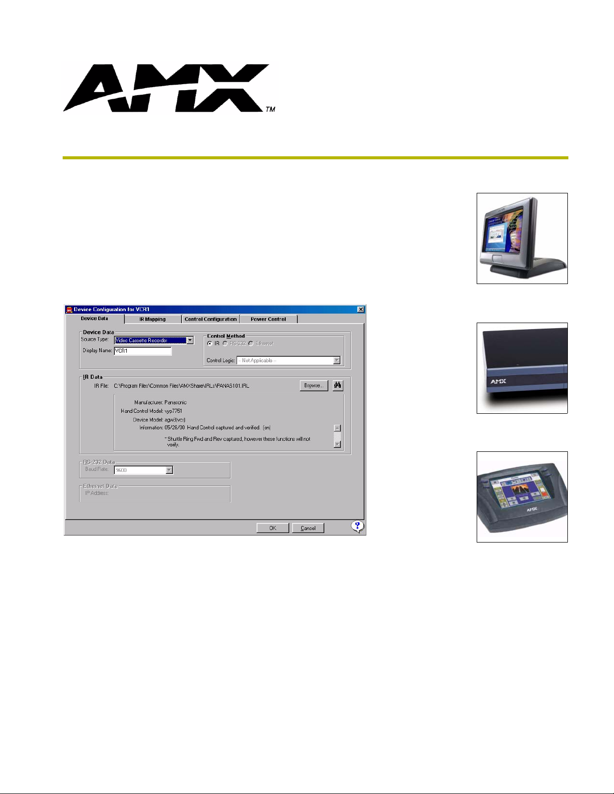
Format of IR Files For Audio Sources
Many of the devices supported by DXP-HT are IR-controlled. AMX has a library of thousands of
IR files for equipment, many of which have been captured to a standard template. DXP-HT uses
this template for its IR codes. In some cases the IR file for new equipment may not have been
captured or is not available for download from the AMX website. Or perhaps the IR file is available
on the web but one or two codes were not captured in the right channels. In these cases it may be
necessary for the installer to capture the IR codes or, at least, modify the IR file.
When capturing or making changes the installer needs to know in which channel each IR code
should reside. If the installer needs to capture an IR remote, or make changes to an IR file, the IR
functions must be captured in the correct channels to work properly with DXP-HT.
The DXP-HT Wizard lets you map the captured IR codes with a list of supported features. Refer to
the DXP-HT Programmer’s Guide for details.
10
DXP-HT v1.3 - On-Site Installer’s Guide
Page 15

On-Site Installer’s Guide - Overview
Common Mistakes
The most common mistake made is modifying the software and then using the application to make
changes. As mentioned before, all software changes outside of the special CUSTOM.AXI file will
be overwritten. Only modify the source code generated by DXP-HT if there is a strong desire to
alter the behavior of the code. To add features, new subsystems, etc. make the changes in the
custom file to save yourself the frustration.
DXP-HT is not a "simple" NetLinx program. Because of the scope and number of features designed
into the system, the code can be quite daunting to someone looking at it, even an experienced
NetLinx programmer. Installers with NetLinx experience should not expect to be able to modify the
software the first time they see it. Most of the features are tied into another feature or affect another
part of the software. The architecture of the system design and the function of the file being
modified should be understood prior to proceeding with changes.
Another common mistake is forgetting to properly address a device. Unless all devices are
addressed as defined in the report file the system will not work as desired.
XP-HT v1.3 - On-Site Installer’s Guide
11
Page 16

On-Site Installer’s Guide - Overview
12
DXP-HT v1.3 - On-Site Installer’s Guide
Page 17

Understanding the Report File
Overview
The report file (report.html) automatically generated by Design XPress should be used as a step-bystep guide to installing the system. The report is broken down into the following five sections:
Installation Instructions
Device Addressing
Wiring/Connections
General Information
AMX Recommended Equipment List
Installation Instructions
This section of the report indicates which files need to be downloaded, and describes device
mapping, working with IR files, compile and download operations (via NetLinx Studio), how to
FTP externally, and how to reboot the NetLinx master. An example would be:
1. Verify NetLinx Master Firmware is the latest available.
Understanding the Report File
2. Verify NXI Firmware is the latest available.
3. Open the project in NetLinx Studio.
4. Address each device as specified in the Device Addressing section of this report.
5. Configure each Modero panel to communicate via Ethernet
6. Compile the project.
7. Go to the download screen. Make sure communications settings are correct.
8. Select all files in the project and download.
9. Using an FTP program, FTP all .TXT files and .HTML files in the project directory to the root
directory on the NetLinx Master.
10. Reboot the Master for the changes to take effect.
Device Addressing
This section defines the device IDs of all the devices defined by DXP-HT. The devices listed in this
section must be set to the given device IDs. If this is not done the system will not behave properly.
This section is divided up by device type: touch panels and miscellaneous.
Most devices will need to have their device IDs set using NetLinx Studio. The exceptions to this are
the touch panels. Their device IDs must be set from the setup screen on the panel itself. Make sure
when the device ID is set that the number of devices used on the touch panel is also set. DXP-HT
uses 4 devices on each touch panel. So, if the touch panel is set to use device ID 128 with 4 devices
used, that panel will actually occupy device IDs 128, 129, 130, and 131.
When using G4 panels, you do not need to set the number of devices used.
XP-HT v1.3 - On-Site Installer’s Guide
13
Page 18

Understanding the Report File
Examples:
Touch Panel:
Touch Panel 01 (TP) of type: CV10 NI-4000 device address 128:1:0 using
4 devices
Touch Panel 01 (TP 1) of type: Modero CV17 NXI Controller device
address 10501:1:0, Menu style: Static
Miscellaneous:
NetLinx NXI device address is 5001:1:0
AMX ALD-D48 lighting controller, device address is 5600:1:0
Wiring/Connections
This section details the locations where all of the cables will connect. It will define the connections
for all of the AMX equipment as well as all source and display equipment, IR ports, and any other
connection that must be made.
Example #1:
IR Devices
DVD
Connected to NXI Controller port 10
IR Pulse Time 5/10 seconds
Time Gap Between IR Pulses 5/10 seconds
IR Pulse Time for Power 5 seconds
Time Gap Between IR Power Pulses 5 seconds
Uses Carrier Signal
XCHMode 0
Serial Devices
Switcher
Connected to NXI Controller port 1
Using Control Logic Autopatch Precis
Baud rate 9600
EtherNet Devices
MAX 2_1
IP Address 192.168.168.168
Using Control Logic MAX-IMS, at Output Zone # 1
Relay Devices
Screen
Connected to NXI Controller port 7
1st relay action labeled Up connected to relay #1
2nd relay action labeled Down connected to relay #2
3rd relay action labeled Stop connected to relay #3
Example #2:
CD Changer is connected to NetLinx using IR port 2, IR pulse time 3/10
second
DVD is connected to switcher input 1
14
Go through this section of the report one item at a time and perform each connection. Use this
section as a list of connections to make and check them off as you go.
DXP-HT v1.3 - On-Site Installer’s Guide
Page 19

Understanding the Report File
General Information
This section of the report details the user interface file names for each touch panel, which files need
to be transferred to the Master, lighting scene addresses, file names of the generated NetLinx
software, etc. Examples:
IR Files
TV, C:\Program Files\Common Files\AMXShare\IRLs\Sony TV Discrete.irl, NXI
Controller device address 5001:12:0
CD, C:\Program Files \IRLIB\sony0398.irl, NXI Controller device address
5001:8:0
DSS, C:\Program Files \IRLIB\hughes01.irl, NXI Controller device address
5001:9:0
DVD, C:\Program Files \IRLIB\kenwoo19.irl, NXI Controller device address
5001:10:0
DVD_1, C:\Program Files \IRLIB\kenwoo19.irl, NXI Controller device address
5001:11:0
The following files need to be loaded into the Master via FTP
CD: C:\Program Files\AMX Control Disc\Design XPress Home Theater
\Projects\QRA Test Rack build 5\Rev 3\cd_cd.txt
DVD: C:\Program Files\AMX Control Disc\Design XPress Home Theater
\Projects\QRA Test Rack build 5\Rev 3\dvd_dvd.txt
DVD_1: C:\Program Files\AMX Control Disc\Design XPress Home Theater
\Projects\QRA Test Rack build 5\Rev 3\dvd_dvd_1.txt
Misc: Report.HTML
Lighting Scenes
Lighting Address=1 Button=102 Scene=Room Off
Lighting Address=1 Button=1 Scene=Scene 1
Lighting Address=1 Button=2 Scene=Scene 2
Lighting Address=1 Button=3 Scene=Scene 3
Lighting Address=1 Button=4 Scene=Scene 4
Lighting Address=1 Button=5 Scene=Scene 5
IR File Mapping
CDP1
Touch Panel Button Function Channel
Digit 0 10 (O) 10
Digit 1 1 (F) 11
Digit 2 2 (G) 12
Digit 3 3 (H) 13
Digit 4 4 (I) 14
Digit 5 5 (J) 15
Digit 6 6 (K) 16
Digit 7 7 (L) 17
Digit 8 8 (M) 18
Digit 9 9 (N) 19
Next Track AMS <<| 4
Pause PAUSE [] 3
Play play < 1
Previous Track AMS |<< 5
Random/Shuffle SHUFFLE (B) 60
Scan Back SCAN << 7
Scan Forward SCAN << 6
Stop STOP [] 2
Clear CLEAR (CLEAR) 55
Continue CONTINUE (A) 59
Select 141
XP-HT v1.3 - On-Site Installer’s Guide
15
Page 20

Understanding the Report File
Channel Presets
DSS
Preset Channel Uses Logo Included in All Presets,
and the following categories
CNN 202 Yes News
Fox News Channel 360 Yes News
MSNBC 356 Yes News
Fox Sports World 613 Yes
Bloomberg Television 353 Yes News
ESPN 206 Yes
HBO 2 502 Yes
ESPN 2 209 Yes
Fox Sports Net Southwest 643 Yes
Fox Sports Net Chicago 639 Yes
Fox Sports Net North 641 Yes
TBS Superstation 247 Yes
Fox Sports Net Northwest 651 Yes
The Golf Channel 605 Yes
MTV2 333 Yes
HBO 501 Yes
Cinemax 512 Yes
CNN International 358 Yes News
Comedy 249 Yes
Cartoon Network 296 Yes
TNT 245 Yes
BBC America 264 Yes Childrens
MTV 331 Yes
VH1 335 Yes
ESPNEWS 207 Yes News
VH1 Classic 337 Yes
Headline News 204 Yes
NetLinx include files copied to C:\PROGRAM FILES\AMX CONTROL DISC\DESIGN
XPRESS Home Theater\Projects\DXP-HT Sample Project\Rev 2\
_Define Constant.axi
_Define Event.axi
_Define Start.axi
_Define Structure.axi
_Define Variable.axi
BUTTON_EVENT - Cable.axi
BUTTON_EVENT - CD.axi
BUTTON_EVENT - Display.axi
BUTTON_EVENT - DSS.axi
BUTTON_EVENT - DVD.axi
BUTTON_EVENT - Environment.axi
BUTTON_EVENT - Global.axi
BUTTON_EVENT - Main Menu.axi
BUTTON_EVENT - MAX.axi
BUTTON_EVENT - MP3.axi
BUTTON_EVENT - PVR.axi
BUTTON_EVENT - Switcher.axi
BUTTON_EVENT - VCR.axi
CD List Management.axi
Control.axi
ControlLogics.axi
Custom.axi
Custom Macro Functions.axi
DB Access.axi
Debug.axi
Globals.axi
Macro Engine.axi
Macro Engine Handlers.axi
Main Menu.axi
Queue_and_Threshold_Sizes.axi
TP.axi
16
DXP-HT v1.3 - On-Site Installer’s Guide
Page 21

Understanding the Report File
NetLinx module (TKO) files copied to C:\Program Files\AMX Control Disc\Design XPress
Home Theater\Projects\QRA Test Rack build 5\Rev 3\
AMX_MAX_IMS_MMS_Comm.tko
AMX_MAX_IMS_MMS_Comm.tko
AMX_MAX_IMS_MMS_Comm.tko
AutoPatch_Precis_Comm.tko
GENTNER_XAP400_COMM.tko
GENTNER_XAP400_UI.tko
Runco_VX_1000ci_Comm.tko
SAMSUNG_SyncMaster_403T_Comm.tko
Tandberg6000_COMM.tko
tandberg6000_ui.tko
Xiva-Comm.tko
User Interface Files
Touch panel file for TP 1 is 'TP CV17 TP 1.TP4'
Macros
This section of the report details all Macros added in the system, as well as a list of all steps
contained in each Macro. Use this section to ensure that all of the intended functionality for each
Macro has been added.
Example:
Macro: MAX 1_1 Navigation and Routing
Send Plasma command 'Power On'
Execute delay of 1 second
Send Plasma command 'BNC'of type Video Inputs
Execute delay of 1 second
MAX 1_1 Routes to Plsm BNC on Device Switcher
Execute delay of 1 second
Execute lighting scene 'Scene 5'
Execute 'Close' using relay device Window, state = PUSH
Execute delay of 2 seconds
Execute 'Close' using relay device Window, state = RELEASE
AMX Recommended Equipment List
This section of the report lists all of the AMX equipment that will be needed to build, install, and
run the system. Both model numbers and descriptions are given to make ordering the equipment a
simple process.
Example:
NXC-ME260/64 NetLinx Master Card with Ethernet [1]
PSN6.5 12 VDC, 6.5A Power Supply to power NetLinx controller
and each Modero panel [2]
ABS AXlink Bus Strip [1]
NXT-CV17 17" Modero Widescreen [1]
Note: use NXD-CV17 for wall mount
MAX-MMS MAX MultiMedia Server [1]
XP-HT v1.3 - On-Site Installer’s Guide
17
Page 22

Understanding the Report File
18
DXP-HT v1.3 - On-Site Installer’s Guide
Page 23

Using NetLinx Studio
If you did not select to automatically open the project file within NetLinx Studio, you will have to
manually locate the file and open it within NetLinx Studio. Opening the AXS project in NetLinx
Studio allows you to download the program data and user interface files to the NetLinx system.
Upon completion of the DXP-HT application the next step is to use NetLinx Studio to open the
created project file. From this point on, this document will assume the installer has a good
understanding of NetLinx Studio (it can be a difficult installation if the installer is a first time DXPHT user and a first time NetLinx Studio user).
To open the workspace, use the Open Workspace option in the File menu and traverse to the path
where your project file resides. Once the workspace is open, expand all branches of the Navigator
view to see the files that have been created in the project. There is also an option in DXP-HT (upon
completion of a project) that provides a popup dialog that gives you the option to automatically
open the newly created workspace in NetLinx Studio.
There is only one file under the Source Code branch: Main.axs. This is the main file and contains
most of the system configuration information entered into the application/wizard. All other
NetLinx software files are under the Include branch of the tree. There are a lot of include files
because the software is broken up by function. For example, Lights_Tp.axi contains the software
for controlling lights via the touch panels. All of the touch panel files are located under the User
Interface branch. The text files and report file are located under the Other branch.
Using NetLinx Studio
To compile your project, open up the main source file and then select the Build Active System
option under the Build menu (or click on the Build Active System icon from the toolbar below the
Main menu). Any time changes are made the software has to be compiled.
Setting Up the Master
Some files will need to be transferred to the Master outside of NetLinx Studio, using FTP (file
transfer protocol). To accomplish this, communication cannot take place over a serial cable using
the program port on the Master. Instead, it must be done via Ethernet. Therefore it is always
recommended that all downloads and communication between NetLinx Studio and the Master be
done via Ethernet. Using Ethernet also results in faster transfers.
When the NetLinx Master ships, it is configured for serial communication at 38,400 baud. To
configure the NetLinx Master to use Ethernet communication requires a serial connection.
1. Launch NetLinx Studio (default location is Start >Programs > AMX Control Disc > NetLinx
Studio > NetLinx Studio 2.1).
2. Select Settings > Master Communication Settings, from the Main menu, to open the Master
Communication Settings dialog.
3. Click the Communications Settings button to open the Communications Settings dialog.
4. Click the NetLinx Master radio button (from the Platform Selection section) to indicate that
you are working with a NetLinx Master (such as the NXC-ME260/64 or NI-Series of
Integrated Controllers).
5. Click the Serial radio button (from the Transport Connection Option section) to indicate you
are connecting to the Master via a (Serial) COM port.
XP-HT v1.3 - On-Site Installer’s Guide
19
Page 24

Using NetLinx Studio
6. Click the Edit Settings button to open the Serial Settings dialog.
7. Make sure the correct serial port is selected and the baud rate is correct on the Master Comm
8. Click OK three times to close the open dialogs and save your settings.
9. Click on the OnLine Tree tab in the Workspace window to view the devices on the System. The
10. Right-click on the Empty Device Tree entry and select Refresh System to establish a new
Obtaining the Master's IP Address:
1. Once a connection is made, select Diagnostics > Network Addresses from the Main menu to
2. Verify the System number corresponds to the value previously assigned in the Device
Settings dialog (in the Tools menu). Set the COM port parameters for the selected COM port
being used for communication to the NetLinx Master. Default parameters are: COM1, 38400,
8 Data Bits, No Parity, 1 Stop Bit, and No Flow Control.
default System value is one.
connection to the System's Master and refresh the list with online system devices. The
communication method is highlighted in green on the bottom of the NetLinx Studio window.
access the Network Addresses dialog.
Addressing tab and verify that zero (0) is entered into the Device field.
3. Verify that NetLinx appears in the Host Name field.
4. Click the Use DHCP radio button from the IP Address section.
5. Click the Get IP Information button to read the IP Address obtained by the Master from the
DHCP Server and configure the unit for DHCP usage.
6. Note the obtained IP Address. This information is later entered into the Master
Communication Settings dialog and used by NetLinx Studio 2.1 (or higher) to communicate to
the Master via an IP. This address is reserved by the DHCP server and then given to the Master.
7. Click the Set IP Information button to retain the IP Address on the Master. A popup window
then appears to notify you that Setting the IP information was successful and it is
recommended that the Master be rebooted.
8. Click OK to accept the new changes.
9. Click the Reboot Master button and select Ye s to close the Network Address dialog. This
process closes the Network Addresses dialog and directs you to the Reboot the Master
Controller dialog.
10. Click Continue (from the Reboot Controller dialog) and wait for the System Master to reboot
and retain the newly obtained DHCP Address. The STATUS and OUTPUT LEDs should begin
a alternately blink during the incorporation. Wait until only the STATUS LED is the only LED
to blink.
11. By default, the Master ships with the option set to wait for a server to assign it an IP Address
via DHCP. If there is no DHCP server on the network it will greatly increase startup time while
the Master waits for an address to be assigned. Therefore, it is recommended that the IP
Address be set to a Static Address.
20
DXP-HT v1.3 - On-Site Installer’s Guide
Page 25

Using NetLinx Studio
Therefore, it is recommended that the IP Address be set to a Static Address. To do this:
1. Verify that NetLinx appears in the Host Name field.
2. Click the Specify IP Address radio button from the IP Address section.
3. Enter the IP Address, Subnet Mask, and Gateway information into their respective fields.
4. Click the Set IP Information button to retain a known IP Address (obtained from the System
Administrator) on the specified System Master.
5. Click OK to accept the new changes.
6. Click the Reboot Master button and select Ye s to close the Network Address dialog. This
process closes the Network Addresses dialog and directs you to the Reboot the Master
Controller dialog.
7. Click Continue (from the Reboot Controller dialog) and wait for the System Master to reboot
and retain the newly obtained DHCP Address. The STATUS and OUTPUT LEDs should begin
to alternately blink during the incorporation. Wait until the STATUS LED is the only LED to
blink.
8. Right-click associated System number and select Refresh System. This establishes a new
connection to the specified System and populates the list with devices on that system.
Addressing the System
The NetLinx NXI system used by DXP-HT consists of two devices: a Master and (serial ports,
relays, IR ports, and I/O ports). Each is addressed separately on the NetLinx bus with a unique
device ID. There is no need to modify the device ID of the Master unless the system is being
installed in a multi-Master system. However, the device ID of the NXI may need to be changed.
DXP-HT expects this device ID to be 5001:1:0.
To modify device IDs in NetLinx the current ID must be known so it can be directly told to change
to a new device ID. To determine the current device ID of the NXI use the online tree in NetLinx
Studio to view a list of all the current online devices the Master recognizes. This list will show the
device ID and the type of device. Find the one that identifies itself as "NXI", and note its device ID.
To change the system ID:
1. Right-click on any System item listed in the OnLine Tree tab of the Workspace and select
Device Addressing (from the pop-up list) or Select Diagnostics > Device Addressing from the
Main menu.
2. Select the Change System selection box, from the System to Change section.
3. Enter both the current and new system address values. Enter the new device ID, 5001, in the
Change To Device field.
4. Click the Change Device/System Number button. This configures the Master to accept the
new value and incorporate the information. Your online tree should change to reflect the new
ID of the NXI. The system information (in the OnLine Tree tab of the Workspace window)
refreshes and then displays the new information.
5. Click Done to close the Device Addressing dialog and return to the main program.
6. Select Tools > Reboot the Master Controller to access the Reboot the Master dialog, then
click Continue to reboot the Master and incorporate any changes. Allow 20 - 30 seconds for
XP-HT v1.3 - On-Site Installer’s Guide
21
Page 26

Using NetLinx Studio
7. Right-click the associated System number and select Refresh System to establish a new
8. Use Ctrl+S to save your existing NetLinx Project with the new changes.
Addressing the Devices
Each device used by DXP-HT and identified in the report file must have a unique NetLinx ID.
Therefore, each device will need to be addressed so it can be properly controlled. The easiest
method for setting device addresses is to connect each device onto the bus one at a time. The online
tree in NetLinx studio can be used to quickly identify which device was just added to the system.
When a device is plugged into the bus it should display in the online tree in a matter of seconds. If a
device is unplugged from the bus it will take a little longer to disappear because the Master is
constantly sampling the bus for devices. When a new device is discovered it is immediately added
to the system. However, if a device disappears from the bus, the Master will give it several retries
before giving up and removing it.
By addressing devices one at a time in this fashion it is very easy to do the addressing away from
the job site (office, home, etc.). This can save time and legwork while on-site where there are
always a million other things to get done.
the Master to reboot. The STATUS and OUTPUT LEDs should begin to alternately blink
during the incorporation. Wait until only the STATUS LED is the only LED to blink.
connection to the specified Master and refresh the System list with devices on that system.
Once the new device shows up in the online tree, its device ID and device type is displayed. Use
this device ID to change to the new value specified in the report file.
To change the device ID:
1. Access the Device Addressing dialog by either one of these two methods:
Right-click on any system device listed in the OnLine Tree tab of the Workspace and
select Device Addressing (from the pop-up list).
Select Diagnostics > Device Addressing from the Main menu.
2. Select the Change Device checkbox, from the Device to Change section.
3. Enter both the Current and New Device address values for the target NetLinx device. Be sure to
enter the new corrected device ID (as specified in the report file) in the Change To Device field.
4. Click the Change Device/System Number button. Make sure the Change To Device check
box is selected and the Change To System check box is not selected. This configures the
specified Master to accept the new value for the NetLinx device and incorporate the
information (the system information in the Workspace window refreshes and then displays the
new information).
5. Click Done to close the Device Addressing dialog.
6. Select Tools > Reboot the Master Controller to access the Reboot the Master dialog, then
click Continue to reboot the Master and incorporate any changes. Allow 20 - 30 seconds for
the Master to reboot. The STATUS and OUTPUT LEDs should begin to alternately blink
during the incorporation. Wait until only the STATUS LED is the only LED to blink.
22
7. Right-click the associated System number (from the OnLine Tree tab of the Workspace
window) and select Refresh System to establish a new connection to the specified Master and
refresh the System list with devices on that system.
DXP-HT v1.3 - On-Site Installer’s Guide
Page 27

Using NetLinx Studio
Downloading Software and Transferring Files
In order for the system to operate, the NetLinx program and all supporting files (touch panel files,
IR files, text files, etc.) must be downloaded to the master. NetLinx studio can be used for most
downloads, but any file in the Other branch of the project tree will need to be loaded on the master
using FTP (file transfer protocol).
This document will assume the user knows how to download files using NetLinx Studio. Compile
the main software file (main.axs) and download it to the master. Download all touch panel files and
IR files for each audio source. Since the include files are compiled into the main program there is
no need to download them individually.
All other files such as CD titles, DSS favorites, and tuner presets must be downloaded using an FTP
program. There are many of these available on the web, most of them freeware. Connect to the
master and download all of the required files into the root directory (top-most directory) of the
master.
Once everything is downloaded, the master will require a reboot to load the new configuration.
Running the First Time
The master ships with a default message buffer threshold which may be too small for the Design
XPress system. Fortunately there is a solution to this problem.
Telnet to the master by going to the Windows Start Menu and selecting Run (alternatively, you can
launch a TelNet session through NetLinx Studio, via the Tools menu).
Enter the command
(ex.
TELNET 192.168.0.2). Log in to the master and enter the following command:
SET THRESHOLD.
TELNET AA.BB.CC.DD, where AA.BB.CC.DD is the IP address of the master
The system will prompt for three threshold values: Interpreter, LonTalk, and IP. Set each of these to
a value of 500.
Exit the telnet session by issuing the command
EXIT. Reboot the NetLinx master for the changes to
take effect. The changes will be permanent, so each time the system restarts it will start with the
higher threshold values.
Startup
When the Master boots it is a bit tricky to determine when the system is completely operational.
Each touch panel connected to the system displays a message box "System is ready" indicating that
the reboot is complete, and the system is ready to operate. In addition, the panels will flip to the
Logo page when they are ready. Depending on the number of devices, touch panels, etc. on the
system, the reboot could take several minutes.
XP-HT v1.3 - On-Site Installer’s Guide
23
Page 28

Using NetLinx Studio
24
DXP-HT v1.3 - On-Site Installer’s Guide
Page 29

Using NetLinx Studio
XP-HT v1.3 - On-Site Installer’s Guide
25
Page 30

AMX reserves the right to alter specifications without notice at any time.
ARGENTI NA • AUST RALIA • BE LGIUM • B RAZIL • C ANADA • CH INA • ENGL AND • FRA NCE • GER MANY • GR EECE • HO NG KONG • INDIA • IN DONESIA • ITALY • JAPAN
LEBANON • MALAYSIA • MEXICO • NETHERLANDS • NEW ZEALAND • PHILIPPINES • PORTUGAL • RUSSIA • SINGAPORE • SPAIN • SWITZERLAND • THAILAND • TURKEY • USA
ATLANTA • BOSTON • CHICAGO • CL EVELAND • DALLAS • DE NVER • INDIANAPOLIS • LOS ANGELES • MINNEAPOLIS • PHILADELPHIA • PHOENIX • PORTLAND • SPOKANE • TAMPA
3000 RESEARCH DRIVE, RICHARDSON, TX 75082 USA • 800.222.0193 • 469.624.8000 • 469-624-7153 fax • 800.932.6993 technical support • www.amx.com
2005 AMX Corporation. All rights reserved. AMX, the AMX logo, the building icon, the home icon, and the light bulb icon are all trademarks of AMX Corporation.
©
033-004-2670 1/05
*In Canada doing business as Panja Inc.
 Loading...