

Page 1
Design XPress Home Theater
version 1.3
instruction manual
Programmer’s Guide
Software
Page 2

Software Warranty Agreement
PRE-RELEASE CODE.
Portions of the AMX Software may, from time to time, as identified in the AMX Software, include PRE-RELEASE CODE
and such code may not be at the level of performance, compatibility and functionality of the final code. The PRERELEASE CODE may not operate correctly and may be substantially modified prior to final release or certain features
may not be generally released. AMX is not obligated to make or support any PRE-RELEASE CODE. ALL PRERELEASE CODE IS PROVIDED “AS IS” WITH NO WARRANTIES.
LIMITED WARRANTY.
AMX warrants that the AMX Software will perform substantially in accordance with the accompanying written materials
for a period of 30 days from the date of receipt. AMX DISCLAIMS ALL OTHER WARRANTIES, EITHER EXPRESS OR
IMPLIED, INCLUDING, BUT NOT LIMITED TO IMPLIED WARRANTIES OF MERCHANTABILITY AND FITNESS FOR
A PARTICULAR PURPOSE, WITH REGARD TO THE AMX SOFTWARE. THIS LIMITED WARRANTY GIVES YOU
SPECIFIC LEGAL RIGHTS.
LICENSEE REMEDIES.
AMX's entire liability and your exclusive remedy shall be repair or replacement of the AMX Software that does not meet
AMX's Limited Warranty and which is returned to AMX. This Limited Warranty is void if failure of the AMX Software has
resulted from accident, abuse, or misapplication. Any replacement AMX Software will be warranted for the remainder
of the original warranty period or 30 days, whichever is longer. Outside the United States, these remedies may not
available.
NO LIABILITY FOR CONSEQUENTIAL DAMAGES. IN NO EVENT SHALL AMX BE LIABLE FOR ANY DAMAGES
WHATSOEVER (INCLUDING, WITHOUT LIMITATION, DAMAGES FOR LOSS OF BUSINESS PROFITS, BUSINESS
INTERRUPTION, LOSS OF BUSINESS INFORMATION, OR ANY OTHER PECUNIARY LOSS) ARISING OUT OF
THE USE OF OR INABILITY TO USE THIS AMX PRODUCT, EVEN IF AMX HAS BEEN ADVISED OF THE POSSIBILITY OF SUCH DAMAGES. BECAUSE SOME STATES/COUNTRIES DO NOT ALLOW THE EXCLUSION OR LIMITATION OF LIABILITY FOR CONSEQUENTIAL OR INCIDENTAL DAMAGES, THE ABOVE LIMITATION MAY NOT
APPLY TO YOU.
If you acquired this product in the United States, this Agreement is governed by the laws of the State of Texas.
Should you have any questions concerning this Agreement, or if you desire to contact AMX for any reason, please
write: AMX Corporation, 3000 Research Drive, Richardson, TX 75082.
Page 3

Table of Contents
Table of Contents
Introduction ...............................................................................................................1
DXP-HT v1.3 - New Features............................................................................................ 1
Minimum System Requirements .............................................................................................. 3
Required Software Applications ............................................................................................... 3
DXP-HT Version Information.................................................................................................... 4
Downloading the Application .................................................................................................... 4
Web Update ............................................................................................................................. 4
Supported Subsystems and Equipment ............................................................................ 5
Modero (G4) touch panels ....................................................................................................... 5
G3 touch panels ...................................................................................................................... 6
G3 panels do not support the following.................................................................................... 6
AMX NetLinx Integrated Controllers......................................................................................... 6
CD Players .............................................................................................................................. 6
DVD Players ............................................................................................................................ 6
MAX Servers by AMX .............................................................................................................. 7
Lighting..................................................................................................................................... 7
MP3 Players............................................................................................................................. 7
Plasma Displays ...................................................................................................................... 8
Receivers ................................................................................................................................ 8
User Interfaces ........................................................................................................................ 8
Video Cassette Recorders (VCRs) ......................................................................................... 8
Video Projection Devices ........................................................................................................ 9
DXP-HT Main Screen...................................................................................................... 10
DXP-HT Menu Bar .......................................................................................................... 11
File Menu ............................................................................................................................... 11
Edit Menu ............................................................................................................................... 11
View Menu ............................................................................................................................. 11
Help Menu.............................................................................................................................. 12
Project List....................................................................................................................... 12
Project Selection List Context Menu ...................................................................................... 13
Project Sorting........................................................................................................................ 13
Main Screen Command Buttons ............................................................................................ 14
User Information dialog ................................................................................................... 14
Setting Program Preferences .......................................................................................... 15
Getting Started ................................................................................................................ 17
To launch the DXP-HT Project Wizard................................................................................... 17
To Create a New Project........................................................................................................ 17
XP-HT v1.3 - Programmer’s Guide
i
Page 4

Table of Contents
Using the DXP-HT Project Wizard .........................................................................19
Before You Start - Required Information......................................................................... 19
Launching the DXP-HT Project Wizard........................................................................... 19
Project Wizard Navigation Controls ....................................................................................... 20
System Information dialog............................................................................................... 21
Adding a Device to the Project............................................................................................... 22
Adding IR-Controlled Devices to the Project.......................................................................... 23
Adding Serial-Controlled Devices to the Project .................................................................... 24
Adding IP-Controlled Devices to the Project .......................................................................... 25
Adding a MAX-IMS or MMS Server to the System ................................................................ 25
Duplicating a Source Device .................................................................................................. 26
Device Considerations when using New Features................................................................. 26
Device Configuration dialog ............................................................................................ 27
Device Configuration dialog - Device Data tab ...................................................................... 27
Device Configuration dialog - IR Mapping tab........................................................................ 30
Mapping a Function................................................................................................................ 31
Removing a Mapped Function ............................................................................................... 31
Device Configuration dialog - Control Configuration tab ........................................................ 32
Device Configuration dialog - Power Control tab ................................................................... 33
Working with MAX Servers .................................................................................................... 34
Which Screens? dialog ................................................................................................... 35
Audio/Video Inputs dialog ............................................................................................... 36
Surround Sound Presets dialog ...................................................................................... 37
Adding a Surround Sound Mode ............................................................................................ 38
Lighting Presets dialog.................................................................................................... 39
Deleting a Lighting Preset ...................................................................................................... 39
Inserting a New Lighting Preset into Lighting Presets list: ..................................................... 39
Editing a Lighting Preset: ....................................................................................................... 39
Resorting the Presets List: ..................................................................................................... 41
Note for ALD-D48 Lighting Systems ...................................................................................... 41
Note for Radia Lighting Systems............................................................................................ 41
Touch Panel Interfaces dialog......................................................................................... 42
To add a new Touch Panel Interface ..................................................................................... 42
Use Picture Frame for Inactivity Page.................................................................................... 43
Use TakeNote ........................................................................................................................ 43
Menu Style for All Touch Panels ............................................................................................ 43
Exclude from Navigation Menu .............................................................................................. 43
Choose Touch Panel Theme dialog................................................................................ 44
Choose Touch Panel Background dialog............................................................................... 45
Choose Touch Panel Buttons dialog...................................................................................... 45
ii
DXP-HT v1.3 - Programmer’s Guide
Page 5

Table of Contents
Choose Touch Panel Text Colors dialog................................................................................ 45
Channel Preset Categories dialog................................................................................... 47
To create new Preset Categories........................................................................................... 47
To edit the Display Name for an existing Preset Category .................................................... 48
Channel Preset dialogs ................................................................................................... 48
Relay Control dialog ........................................................................................................ 49
Adding a Relay Control Definition to the list........................................................................... 50
Editing the Display Name for an existing Relay Control Definition......................................... 50
Deleting a Relay Control Definition from the list..................................................................... 50
Presets for Receiver AM/FM Tuner dialog ...................................................................... 51
Adding a Preset to the list ...................................................................................................... 51
Editing the Display Name for an Existing Preset.................................................................... 51
Deleting a Preset from the List............................................................................................... 52
CD Titles dialog ............................................................................................................... 52
Adding a new CD title:............................................................................................................ 53
Editing CD Information ........................................................................................................... 53
Retrieving CD Information (from freedb.org).......................................................................... 53
Removing a CD Title .............................................................................................................. 53
Using the CD Titles Maintenance dialog................................................................................ 53
Adding a new Disc title (CD Titles Maintenance dialog) ........................................................ 53
Editing Disc Information (CD Titles Maintenance dialog)....................................................... 53
Retrieving CD Information from freedb.org (CD Titles Maintenance dialog) .......................... 53
Removing a CD Title (CD Titles Maintenance dialog)............................................................ 54
System Macros dialog ..................................................................................................... 54
Creating a new macro and adding it to the Project ................................................................ 55
Editing an existing Macro within the Project........................................................................... 55
Navigation and Routing Macros ...................................................................................... 57
Building the Project ......................................................................................................... 58
Finishing the Job ............................................................................................................. 59
The Report File ...................................................................................................................... 59
Transferring Preset Button Text to the Master via FTP.......................................................... 60
Transferring CD/DVD Title Information to the Master via FTP............................................... 61
Uploading a Touch Panel File To a Panel.............................................................................. 61
Configuring Computer Control (G4CC) ........................................................................... 62
Configuring TakeNote ..................................................................................................... 63
Configuring i!-Weather .................................................................................................... 63
Configuring i!-TimeManager............................................................................................ 64
The NetLinx Studio Project.............................................................................................. 64
Editing Your Project ............................................................................................................... 64
Opening an Existing Design XPress - Home Theater Project................................................ 64
XP-HT v1.3 - Programmer’s Guide
iii
Page 6

Table of Contents
Copying a Design XPress - Home Theater Project................................................................ 65
Importing a DXP-HT Project................................................................................................... 65
Exporting a DXP-HT Project .................................................................................................. 65
Deleting a DXP-HT Project .................................................................................................... 66
Working With IR Files ............................................................................................67
Selecting an IR File to Use.............................................................................................. 67
Searching for IR Files (Search Criteria) .......................................................................... 67
Scanning Directories for IRL Files................................................................................... 68
Setting the Default IR Files Folder .................................................................................. 68
Editing IR Control Information ......................................................................................... 68
Format of IR Files for Audio Sources .............................................................................. 68
DXP-HT Touch Panel Channel Maps ....................................................................69
Channel Maps (Function Codes) - Overview .................................................................. 69
Function Codes:_keyboardVirtual.......................................................................................... 69
Function Codes: AMFM Tuner ............................................................................................... 71
Function Codes: Cable Menu................................................................................................. 71
Function Codes: Cable Tuner ................................................................................................ 71
Function Codes: Cable Video ................................................................................................ 72
Function Codes: CD Changer ................................................................................................ 72
CD Changer Advanced .......................................................................................................... 72
Function Codes: CD List ........................................................................................................ 73
Function Codes: CD List Action Picker .................................................................................. 73
Function Codes: CD List Keyboard ........................................................................................ 74
Function Codes: CD List - Title Only ...................................................................................... 74
Function Codes: Channel Presets ......................................................................................... 74
Function Codes: Channel Preset Categories......................................................................... 75
Function Codes: Controls....................................................................................................... 75
Function Codes: Debug ......................................................................................................... 75
Function Codes: Display ........................................................................................................ 75
Function Codes: Display Advanced ....................................................................................... 76
Function Codes: Display - Projector....................................................................................... 77
Function Codes: Display Video .............................................................................................. 77
Function Codes: DSS Menu................................................................................................... 77
Function Codes: DSS Tuner .................................................................................................. 78
Function Codes: DSS Video .................................................................................................. 78
Function Codes: DVD ............................................................................................................ 78
Function Codes: DVD Changer Advanced............................................................................. 79
Function Codes: DVD Menu .................................................................................................. 79
Function Codes: DVD Video .................................................................................................. 79
iv
DXP-HT v1.3 - Programmer’s Guide
Page 7

Table of Contents
Function Codes: G4CC .......................................................................................................... 79
Function Codes: HELP-ABOUT ............................................................................................. 80
Function Codes: KBKeyboard................................................................................................ 80
Function Codes: KBShift ........................................................................................................ 80
Function Codes: Lights .......................................................................................................... 80
Function Codes: Logo ............................................................................................................ 81
Function Codes: Macros ........................................................................................................ 81
Function Codes: Macros2 ...................................................................................................... 81
Function Codes: Main Page ................................................................................................... 82
Function Codes: Main Page - Static....................................................................................... 82
Function Codes: MAX Audio .................................................................................................. 82
Function Codes: MAX Genre ................................................................................................. 83
Function Codes: MAX Media Search ..................................................................................... 83
Function Codes: MAX Movie Search ..................................................................................... 84
Function Codes: MAX Playlist ................................................................................................ 84
Function Codes: MAX Tracklist .............................................................................................. 84
Function Codes: MAX Video .................................................................................................. 85
Function Codes: MAX Video Transport.................................................................................. 85
Function Codes: MessageBox ............................................................................................... 85
Function Codes: MM - Sources.............................................................................................. 86
Function Codes: MM - Sources2............................................................................................ 86
Function Codes: MP3 Navigator ............................................................................................ 86
Function Codes: MP3 Player ................................................................................................. 87
Function Codes: Projector Video ........................................................................................... 88
Function Codes: PVR............................................................................................................. 88
Function Codes: PVR Menu................................................................................................... 88
Function Codes: PVR Tuner .................................................................................................. 89
Function Codes: PVR Video .................................................................................................. 89
Function Codes: Receiver...................................................................................................... 89
Function Codes: Receiver Surround ...................................................................................... 90
Function Codes: Receiver Audio In........................................................................................ 90
Function Codes: Receiver AV In ............................................................................................ 91
Function Codes: Relays ......................................................................................................... 91
Function Codes: Select .......................................................................................................... 91
Function Codes: Splash ......................................................................................................... 91
Function Codes: TNadvancedControls .................................................................................. 92
Function Codes: TNcolor picker ............................................................................................. 92
Function Codes: TNcanvas.................................................................................................... 92
Function Codes: TNcontrols................................................................................................... 92
Function Codes: TNkeypad.................................................................................................... 93
XP-HT v1.3 - Programmer’s Guide
v
Page 8

Table of Contents
Function Codes: TNpenOptions............................................................................................. 93
Function Codes: TNtext ......................................................................................................... 94
Function Codes: TNshape ..................................................................................................... 94
Function Codes: Tuner Presets ............................................................................................. 94
Function Codes: VCR ............................................................................................................ 95
Function Codes: VCR Menu .................................................................................................. 95
Function Codes: VCR Tuner .................................................................................................. 95
Function Codes: VCR Video .................................................................................................. 96
Function Codes: Video........................................................................................................... 96
Function Codes: Volume........................................................................................................ 96
Function Codes: Weather ...................................................................................................... 96
Function Codes: WeatherBrowse .......................................................................................... 97
Function Codes: WeatherConfig ............................................................................................ 98
Function Codes: WeatherDownload ...................................................................................... 98
Function Codes: WeatherLocation......................................................................................... 98
Function Codes: WeatherZipCode ......................................................................................... 98
vi
DXP-HT v1.3 - Programmer’s Guide
Page 9

Introduction
Design XPress - Home Theater (DXP-HT)™ is a software package developed to assist AMX
dealers in quickly designing, installing and programming a home theater control system. A home
theater control system created using DXP-HT allows the selection and control of audio/video
sources, audio-surround modes, display devices and room lighting among other functions.
DXP-HT allows control via several types of AMX touch panels (see Supported Touch Panels for
details). A wizard-type front-end graphic user interface (GUI) helps you to quickly step through the
process of entering information specific to the home theater system being programmed.
The DXP-HT Project Wizard also allows you to specify the type of NetLinx Master Controller to
be used to control the system. DXP-HT supports NetLinx Integrated Controllers (NI-700/2000/
3000/4000 and the NXI equipped with an NXC-ME260/64 Master card). The wizard will only
allow you to choose a NetLinx Master that is able to accommodate the devices and functions
specified in your Project.
Once the steps outlined in the wizard are complete, the wizard will automatically generate all
NetLinx program files, touch panel files and a comprehensive report file for the system. While
these auto-generated program files can be used as-is, they can also be modified using NetLinx
Studio™, allowing the dealer to customize the NetLinx code and touch panel files to accommodate
specific client desires and those unique requirements always found in custom installations.
AMX University offers several courses that teach basic and advanced NetLinx
programming and system design concepts. Contact AMX University, or refer to the
Training@AMX University page at http://www.amx.com/ for details and scheduling
information.
Introduction
This manual will take you through the steps required to generate a system using DXP-HT.
DXP-HT v1.3 - New Features
Features new to v 1.3 include:
Enhanced Automation: This new selectable option (in the Touch Panel Interfaces
dialog), allows you to exclude specific buttons from the Navigation menu, such as
Display, Lights, Macros, and Relay buttons. It also allows you to customize the DXP-HT
generated touch panel file information by copying buttons from the underlying pages and
providing that functionality onto the current page.
De-select these radio buttons to specify which buttons will be excluded from the output
touch panel pages (within the project file) for the chosen touch panel.
Refer to the Touch Panel Interfaces dialog section on page 42 for details.
Support for additional Modero Touch Panels: DXP-HT now supports the following
additional Modero panels: NXT/NXD-CV7 (7" Touch Panel with video), MVP-7500
(Wireless Panel), and MVP-8400 (Wireless Video Panel). See the Modero (G4) touch
panels section on page 5 for a full listing of supported G4 panels.
XP-HT v1.3 - Programmer’s Guide
1
Page 10

Introduction
Support for NI-700 NetLinx Integrated Controller: This new controller is treated the
same as any of the other NI Series of Integrated Controllers. If the project requires more
ports than the NI-700 can provide (2 Serial and 1 IR), it is disabled as a system controller
option.
Support For Output Zones on MAX Servers: When adding a MAX (IMS or MMS)
Media Server as a device to your project, you can now specify an Output Zone number.
The Output Zone must be unique per each server used in a project. For example, if a
system has two MMS servers, each MMS could have an Output Zone 1.
Support of remote serial interface (for Display devices): This new option (in the
Device Configuration dialog - Device Data tab for serial devices) provides far-end
control of display devices using serial control ports. This feature allows you to extend the
"reach" of the control system to control an external display device directly by parsing out
Send Commands to the Serial control ports. This was implemented to communicate to
some display devices that are not located near the Master.
If a Video Display (such as a Projector/Plasma and TV) are chosen to be controlled
via Serial (RS-232), two new fields become available within the Device Data section.
Place a checkmark in the Use remote serial interface field to indicate you are using
an external serial interface or leave it unchecked to use a Serial port on the Master.
If this option is checked, you can choose which port on the serial interface to use by
choosing a port from the drop-down list.
Support for i!-TimeManager: This new option (in the System Information dialog),
prompts you to select a time zone and apply Daylight Savings Time rules, if desired.
Refer to the Configuring i!-TimeManager section on page 64 for details.
Support for i!-Weather: This new support appears as a Source Type (in the Device Data
tab of the Device Configuration dialog).
i!-Weather is treated as a source type and not a controlled source.
Only one instance of i!-Weather is allowed within the Source list.
Refer to the Configuring i!-Weather section on page 63 for details.
Support for G4 Computer Control: This new support appears as a Source Type (in the
Device Data tab of the Device Configuration dialog). G4 Computer Control (G4CC) can
be configured as a source type within a system and is also available for use within every
touch panel that resides within the same system.
DXP-HT is not intended to support 3rd party (free) VNC clients that are downloadable
from the Internet.
Refer to the Configuring Computer Control (G4CC) section on page 62 for details.
2
DXP-HT v1.3 - Programmer’s Guide
Page 11

Support for PictureFrame: This new support appears as an option in the Touch Panel
Interfaces dialog page. Selecting this radio box specifies that the output project file for
the chosen touch panel will support the use of the PictureFrame application on the panel's
inactivity page.
Refer to the Touch Panel Interfaces dialog section on page 42 for details.
Support for TakeNote: This new support is added as a selectable option within the
Touch Panel Interfaces dialog page. Selecting this radio box specifies that the output
project file for the chosen touch panel will support TakeNote.
Refer to the Configuring TakeNote section on page 63 for details.
Minimum System Requirements
Windows 2000® (Service Pack 4) with at least 128 MB of installed memory
Windows XP® Professional (Service Pack 1) with at least 256 MB of installed memory
Supported language versions: English, French, German and Spanish
If you are installing NetLinx Studio on a Windows XP or 2000, you must have
Administrator rights to install and run all required System files.
Introduction
Pentium 450 MHZ processor (700 MHZ or faster recommended)
A VGA monitor running at a minimum resolution of 800 x 600
Windows-compatible CD-ROM drive
Mouse (or equivalent pointing device)
Minimum free disk space: 2 GB
Internet Access (for Web Update functionality)
Required Software Applications
The following applications must be installed on your PC before DXP-HT v1.3 can be installed:
Microsoft MDAC v2.6 (or higher)
NetLinx Studio v2.2 (or higher)
TPDesign v3.16 (or higher)
TPDesign4 v2.3 (or higher)
DXP-HT Image File - If the application fails to detect at least one valid set of background
images, and at least one valid set of button images, a separate installation of the Image
File is required. This image installation is available on the DXP-HT section of the
Application Files page on www.amx.com.
XP-HT v1.3 - Programmer’s Guide
3
Page 12

Introduction
DXP-HT Version Information
The DXP-HT version information is located on the Main Screen (under the Exit button). It is
important to have the version information when calling AMX Technical Support. The version
information will allow Tech Support to determine if software updates or patches may be available.
The top number (for example, c1.0.12) is the version number of the Configuration
Database. The Configuration Database determines what options are available in the
wizard for different pieces of A/V equipment.
The lower number (for example, v1.3 Build 2a) is the version and build number of the
actual DXP-HT application. A change in the Version number indicates a change in the
functionality of the application. A change in the Build number indicates an enhancement
in the current functionality of the current revision. Every change to the Version number
will also change the build number, but not every change to the Build number will change
the Version number.
Downloading the Application
Design XPress - Home Theater (DXP-HT) can be downloaded from the AMX web site. You must
first log in as a registered user to the AMX web site then, you can proceed to the Software Center to
download the application. You must download all of the files in the Design XPress - Home Theater
directory, or you may download the compressed file, which contains all of the other files in the
directory.
The two Adobe Acrobat files included (in addition to this one) are:
The Installation Guide is intended for the equipment installer.
The User-Interface Guide describes the Touch Panel UI, and is provided as a reference for
designers, installers, and end-users.
Select Help > Web Update to automatically check for program updates. The program
will prompt you to download and install any updates that are available.
Web Update
The AMX WebUpdate program is a stand-alone application that:
Communicates with the AMX website
Allows a user to select from a list of updateable AMX Software programs
Determines the latest version of the selected applications
Returns a listing of available updates and allows a user to download the selected
installation files
Upon request, launches the installation of those downloads
DXP-HT requires the latest versions of the following applications be loaded prior to
the running the DXP-HT installation executable: NetLinx Studio 2.X, TPD4, and
TPD3. Use the WebUpdate program to obtain the latest versions of these products.
4
DXP-HT v1.3 - Programmer’s Guide
Page 13

Introduction
Select Help > Web Update to launch this application. Refer to the WebUpdate on-line help for
details and instructions.
Supported Subsystems and Equipment
DXP-HT (version 1.3 or higher) supports the following subsystems and equipment:
AMX touch panels
AMX NetLinx Integrated Controllers
CD (Compact Disc) Players
DVD (Digital Video Disc) Players
MAX Integrated Content Servers by AMX
Lighting
MP3 Players
Plasma Displays
User Interfaces (AMX Touch Panels)
Video Cassette Recorders (VCRs)
Video Projection Devices
Receivers
Serial-Interface Devices
For a more up-to-date list of supported devices, refer to the DXP-HT Supported
Devices document, available online at www.amx.com.
Modero (G4) touch panels
• Modero CV7 (NXT/NXD-CV7) 7" Touch Panel with video
• Modero MVP-7500 Wireless Panel
• Modero MVP-8400 Wireless Video Panel
• Modero CA12 (NXT/NXD-CA12) 12" Touch Panel
• Modero CV12 (NXT/NXD-CV12) 12" Touch Panel with video
• Modero CA15 (NXT/NXD-CA15) 15" Touch Panel
• Modero CV15 (NXT/NXD-CV15) 15" Touch Panel with video
• Modero CV17 (NXT/NXD-CV17) 17" Touch Panel with video
The nomenclature " NXT" indicates the table-top (tilt) model, and "NXD" represents
the wall-mount version.
XP-HT v1.3 - Programmer’s Guide
5
Page 14

Introduction
G3 touch panels
• CV6 (AXD-CV6) 6" wired touch panel with video
• CA10 (AXT/D-CA10) 10.4" touch panel
• CV10 (AXT/D-CV10) 10.4" touch panel with video
The nomenclature " AXT" indicates the table-top (tilt) model, and "AXD" represents
the wall-mount version.
G3 panels do not support the following
MAX Integrated Content Server
G4 Computer Control
Take Note!
PictureFrame
AMX NetLinx Integrated Controllers
• NI-700
• NI-2000
• NI-3000
• NI-4000
• NXI equipped with a NXC-ME260/64 Master card
CD Players
• Denon DN-C635
• Denon DN-T625
• Denon DN-T645
• Marantz PMD325
DVD Players
• Adcom GDV850
• Denon DVD2900
• Denon DVD3800
• Denon DVD9000
• Faroudja NRS DVP
• Faroudja DVP-1500
• Integra DPS9.1
• Integra Research RDV1
• Kenwood DV5900M
• Marantz DV8400
• Marantz PMD930
• Marantz VC5400
• Onkyo DVS939
6
DXP-HT v1.3 - Programmer’s Guide
Page 15

Introduction
• Philips Pro DVD 175
• Sony DVP-CX777ES
• Yamaha DVD-C940
• Yamaha DVD-S2300MK2
MAX Servers by AMX
MAX-MMS and MAX-IMS media servers are supported for G4 touch panels only, via Ethernet
control.
• AMX MAX-IMS / MAX-BSM
• AMX MAX-MMS / MAX-AVM
DXP-HT treats these devices essentially the same as any other Ethernet-controlled device (such as
MP3 players). There are just a few points to understand in order to add MAX servers to a DXP-HT
project:
The MAX-MMS and MAX-IMS servers are Ethernet-control only.
They must be used with AMX G4 touch panels (see Supported Touch Panels).
The MAX-AVM A/V Module(s) connected to the MAX-MMS server must be all set to
output to Zone 1.
Refer to the MAX-MMS and MAX-IMS Installation Guides (available online at
www.amx.com) for details.
Lighting
• AMX ALD-D48· Note: (FW build 2.1 or later, via ISCP only)
• AMX Radia·
• Clipsal C-Bus· Note: The Clipsal C-Bus and Dynalite lighting systems (DXP-
• DynaLite
• Lehigh DX2
• LiteTouch 5000LC·
• Lutron GRAFIK Eye·
• Lutron Homeworks Interactive·
• Lutron RadioRA·
• Vantage Q
• Tridonic DALI Note: The Tridonic Lighting System type does not have feed-
• Other Ethernet - user supplied/modified light
• Other Serial - user supplied/modified lights.axi
HT v1.1 or higher) are primarily used outside the U.S.·
back; therefore, the buttons in DXP-HT will not depress to
reflect feedback.
MP3 Players
• Audio ReQuest ARQ2Pro
• Imerge SoundServer
• Integra NAS-2.3 Net-Tune
• Marantz DH9300
XP-HT v1.3 - Programmer’s Guide
7
Page 16

Introduction
Plasma Displays
• Hitachi CMP4201
• Hitachi CMP5000
• Marantz PD5020D
• NEC 42VP4
• Runco PL43HDX
• Runco PL50HDX
• Runco PL61GX
• Samsung SyncMaster 403T
• Sharp LCM3700
Receivers
• Denon AVR2803
• Denon AVR3803
• Denon AVR4802
• Denon AVR-5800
• Denon AVR5803
• Integra DTR 9.1
• Integra Research RDC-7
• Kenwood VR5700
• Kenwood VR5900
• Marantz SR6400
• Marantz SR7300
• Marantz SR7400
• Marantz SR8200
• Marantz SR8300
• Marantz SR9200
• Marantz SR9300
• Onkyo TX-DS989
• Pioneer Elite VSX-47TX
• Sony STR-DA7ES
User Interfaces
AMX Touch Panels
Video Cassette Recorders (VCRs)
• JVC SRS365U
• Marantz MV8300
8
DXP-HT v1.3 - Programmer’s Guide
Page 17

Video Projection Devices
•Barco IQG300
• Barco IQR300
• ChristieDigital DS30
• ChristieDigital RoadRunnerL6
• ChristieDigital VistaS3
• Digital Projection iVisionSXGA
• Eiki LCXG200
• Epson PowerLite7800p
• Epson PowerLite811p
• Epson PowerLite8150i
• Epson PowerLite8300i
• Hewlett Packard XP8010
• InFocus SP7200
• Marantz VP12S1
• Marantz VP12S2
• NEC Any GT Series
• NEC Any LT Series
• NEC Any MT Series
• NEC Any SX Series
• Optoma EzPro H55
• Optoma EzPro750
• Optoma EzPro753
• Optoma EzPro755
• Runco CL710
• Runco DTV1200
• Runco VX1000ci
• Runco VX5000c
• Sharp Electronics PGA10S
• Sharp Electronics PGC45X
• Sharp Electronics XGC50X
• Sharp Electronics XGC60X
• Sharp Electronics XGV10XU
• SIM2 HT300
• Yamaha DPX1000
Introduction
XP-HT v1.3 - Programmer’s Guide
9
Page 18
Introduction
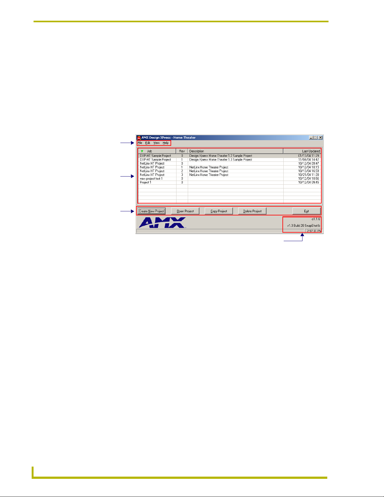
DXP-HT Main Screen
When DXP-HT is launched, the first dialog to be displayed is the Main Screen. Use the Main
Screen as the starting point for creating new projects and opening existing projects. The Main
Screen also contains command buttons for copying projects and deleting projects.
There are three main areas on the Main Screen: the Menu Bar, the Project Selection List,
and the Project Maintenance command buttons.
Version and build information for this version of DXP-HT is listed in the lower right
corner of the Main Screen.
Menu Bar
Project List
Command Buttons
Ver sio n In fo r mat ion
FIG. 1 Design XPress - Home Theater Main Screen
Before creating a new project, you should consider opening the sample project and quickly going
through the various Wizard dialogs, to become familiar with the program.
10
DXP-HT v1.3 - Programmer’s Guide
Page 19

Introduction
DXP-HT Menu Bar
There are four items in the menu bar (on the Main Screen):
File Menu
The Design XPress - Home Theater (DXP-HT) File menu contains several file control options:
• New: Launches the Project Wizard, to create a new DXP-HT project file.
• Open: Opens an existing DXP-HT project file.
• Copy: Allows you to copy the active project file. This option launches the Copy Project
• Delete: Allows you to delete the selected Project from your hard drive.
• Import Project: Allows you to import a file into the Project Selection List.
• Export Project: Allows you to export the active Project.
• Exit: Exits the DXP-HT application.
DXP-HT maintains all of its projects in a single database. To move a project from one DXP-HT
installation to another (for example moving a project from your desktop computer to your laptop),
you must export the project from one computer and import the project on the other computer.
dialog.
The New, Open, Copy, Delete and Exit options are also available via the command
buttons along the bottom of the Main Screen.
Edit Menu
The Edit menu provides several customizable settings for DXP-HT:
•User
Information:
• CD Titles
Maintenance:
• Preferences: Opens the Preferences dialog, containing various global preference settings for
Opens the User Information dialog, where you can enter and save basic user
information for the active Project (User Name, Company Name, Phone and Email Address). The user's name and company are used to auto complete the
Name and Company fields within the Project Information dialog. The user's
phone number and e-mail address are not currently used, but are included for
future DXP-HT features.
Opens the CD Titles Maintenance dialog, where you can add/remove and edit
CD information (Artist and Title), as well as automatically retrieve CD information
from an on-line CD database (via freedb.org, on an internet-enabled computer).
DXP-HT, including enable/disable warning messages within the wizard, select a
progress bar style, and select default folders for Projects and IR files.
View Menu
The View menu contains options for sorting the Project list:
• Sort Projects: Click to access the Project Sorting window. The listed projects can be sorted by
up to four criteria in either ascending or descending order.
XP-HT v1.3 - Programmer’s Guide
11
Page 20

Introduction
Help Menu
The Help menu contains the following options:
• Contents: Opens the online help file.
• Web Update: Will launch the Web Update application to search the AMX site for an update to
the DXP-HT software. Selecting Yes will close DXP-HT, begin the download of the
update, and run the installation of the update. You must have an active Internet
connection for Web Update to work.
• About: Displays the DXP-HT splash screen. The Splash Screen displays the version and
build numbers for DXP-HT. The version and build numbers can also be found in
the lower right hand corner of the Main Screen.
Project List
The Project List is displayed on the Main Screen, along with the main menu and the Create New
Project, Open Project, Copy Project, Delete Project and Exit command buttons.
Each Project is listed by Job Name, Revision, Description, and the Last Updated date.
The projects can be sorted in ascending or descending order for each column. Sorting the projects
makes it easier to locate the current revision of a project or the last modified project. To sort a
column, click on the header cell for the desired column.
Clicking on the header cell will toggle the sort order between ascending and descending
orders. You can also set the sort order by selecting View > Sort Projects.
To open a project, select the project and click on the Open Project command button or
double-click on the selected project.
To delete a project, click on the project then press the Delete Project command button, or
the delete key on the keyboard. The Confirm Delete Request dialog requires you to
confirm deletion.
If a project is not exported before deleting, you will not be able to bring the project
back into DXP-HT for modifications at a later date.
Right-click anywhere in the Project List to open the Project Selection List context menu,
and select Sort to access the Project Sorting feature. The listed projects can be sorted by
up to four criteria in either ascending or descending order. After the desired settings have
been selected click the Sort button to return to the sorted project list.
Once a project has been selected, you can use the File menu or the Command buttons to Open,
Copy or Delete the project.
12
DXP-HT v1.3 - Programmer’s Guide
Page 21

Introduction
Project Selection List Context Menu
Right-click anywhere inside the Project Selection List (on the Main Screen) to open the Project
Selection List context menu, containing shortcuts to several project-related operations:
• New: Launches the DXP-HT Project Wizard to create a new project. This is the same as click-
• Open: Opens an existing project. This is the same as clicking the Open Project command but-
• Copy: Launches the Copy Project dialog, which allows you to save a copy of the selected
• Delete: Deletes the selected Project file. The program prompts you to confirm this action before
• Import: Invokes the Select Import Design XPress Home Theater File dialog, which allows you to
• Export: Invokes the Export Project dialog, which allows you to specify a name and target loca-
• Sort: Displays the Sort Options window, containing the various sort criteria that can be used
ing the Create New Project command button (or selecting File > New).
ton (or selecting (File > Open).
Project file under a new name. Use the options in the Copy Project dialog to specify a
Job Name and enter a description of the file copy. This is the same as clicking the Copy
Project command button (or selecting File > Copy).
the project file is deleted. This is the same as clicking the Delete Project command button (or selecting File > Delete).
Note: If a project is not exported before deleting, you will not be able to bring the project
back into DXP-HT for modifications at a later date.
locate and select a Project file to import. This is the same as selecting File > Import
Project.
tion for the exported Project file. This is the same as selecting File > Export Project.
to sort the Project Selection List. This is the same as selecting View > Sort Projects.
Project Sorting
Right-click anywhere in the Project Selection List (on the Main Screen) to open the Project
Selection List context menu, and select Sort to access the Project Sorting window. The listed
projects can be sorted by up to four criteria (1st, 2nd, 3rd and 4th sort) in either ascending or
descending order:
• None: By default, the sort options are all set to none (no sorting).
• Job Name: Sorts the projects by their Job Names.
• Revision: Sorts the projects by their Revision numbers.
• Description: Sorts the projects alphabetically based on the first character of the project
description.
• Last Updated: Sorts the projects by their most recent save date and time.
Use the four sets of radio buttons to specify up to four sorting operations, in sequential order.
After the desired settings have been selected click the Sort button to return to the sorted project list.
Each of the sort criteria options is based on project data that is either entered or
displayed on the System Information dialog.
XP-HT v1.3 - Programmer’s Guide
13
Page 22
Introduction
Main Screen Command Buttons
Create New Project: Click this command button to launch the Design XPress - Home
Theater Project Wizard. Use the Project Wizard to step through the process of designing
and configuring the system.
Open Project: Click to highlight a project in the Project Selection List, and click the
Open Project command button to open the selected Project. When a project is opened, the
first Wizard dialog (System Information) is displayed.
Copy Project: This option creates a copy of an existing Project, and allows you to give
the copy a new name (via the Copy Project dialog).
Delete Project: This option allows you to delete a Project from the Project Selection List,
and from your hard drive.
To remove a Project from the Project Selection List, without deleting the file from your
hard drive, export the file before deleting. Once exported, you can import the file back
into DXP-HT later.
To export a DXP-HT project, select File > Export Project.
If a project is not exported before deleting, you will not be able to bring the project
back into DXP-HT for modifications at a later date.
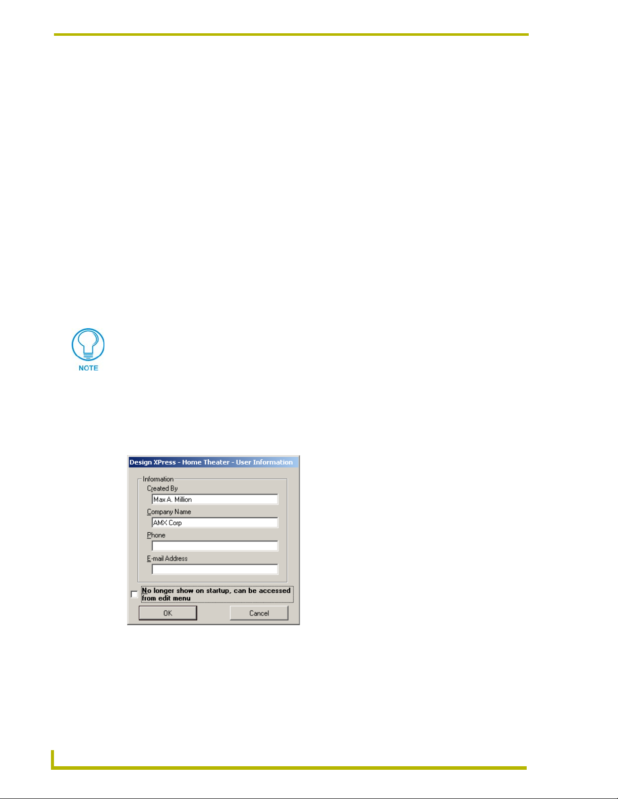
User Information dialog
This dialog (FIG. 2) appears the first time DXP-HT is launched, and prompts you to enter the user
information that will be used to identify the designer of the DXP-HT project (Created By, Company
Name, Phone and E-mail Address).
FIG. 2 User Information dialog
14
Once this information is entered, this dialog will not automatically be shown again at
startup, but can always be accessed via the Edit menu.
The checkbox at the bottom of this dialog can be checked to prevent the dialog from
automatically appearing when the program is started, even if no data has been entered.
DXP-HT v1.3 - Programmer’s Guide
Page 23
Introduction
This dialog is also used by the Design XPress application to fill-in some data within
the project. This means that if you do an initial installation of DXP-HT you will be
asked to enter your information into the User Information dialog. Once this data has
been entered, you will not be asked for it again. Consecutive launches of the
application display the User Information dialog already populated with the preentered data.
If the application is at some point un-installed and then re-installed, you will be
prompted to re-enter you information. If the No longer show on startup selection
has been chosen/enabled, you will no longer be asked to enter any user data into the
User Information dialog.
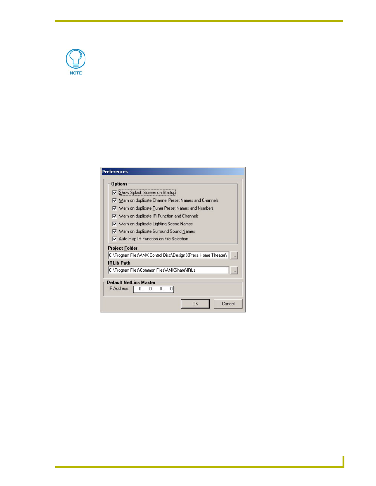
Setting Program Preferences
Select Edit > Preferences to open the Preferences dialog (FIG. 3), where you can set various user
preferences for DXP-HT.
FIG. 3 Preferences dialog
The options in this dialog include:
Show Splash Screen on Startup: A toggling option to show the DXP-HT splash screen
when the program is started. If this item is not checked the splash screen can be viewed
by selecting Help > About.
Warn On Duplicate Channel Preset Names and Channels: Alerts you to the creation
of duplicate channel preset names and channels. All Channel Preset names and channels
must be unique.
Warn On Duplicate Tuner Preset Names and Channels: Alerts you to the creation of
duplicate tuner preset names and channels. All Tuner Preset names and channels must be
unique.
XP-HT v1.3 - Programmer’s Guide
15
Page 24

Introduction
Warn On Duplicate IR Functions and Channels: Alerts you to the creation of
duplicate IR functions and Channels. All IR Function and Channel assignments must be
unique.
Warn On Duplicate Lighting Scene Names: Alerts you to the creation of duplicate
Lighting Scene names. All Lighting Scene names must be unique.
Warn On Duplicate Surround Sound Names: Alerts you to the creation of duplicate
Surround Sound mode names. All Surround Sound names must be unique.
Auto Map IR Function on File Selection: With this option enabled, the Auto Map IR
Functions option (in the IR Mapping tab of the Device Configuration dialog) is enabled
by default.
Project Folder: Click the Browse button to navigate to the desired target folder for all
Project saves. By default, the Project Folder is set to:
Program Files\AMX Control Disc\Design XPress Home Theater\Projects
IRLib Path: Click the Browse button to navigate to the desired target folder for all IR
(*IRL) files. By default, the IR Folder is set to:
Program Files\Common Files\AMXShare\IRLs
If you select a root directory (i.e. C:\) as the target directory, DXP-HT automatically
creates a "Projects" folder for the project files. This folder is only created if you target
a root directory (as apposed to any other existing directory).
Default NetLinx Master: The IP Address field allows you to enter the IP Address of the
target NetLinx Master receiving the Project Files.
16
DXP-HT v1.3 - Programmer’s Guide
Page 25

Introduction
Getting Started
To launch the DXP-HT Project Wizard
Select the sample project (highlight "Sample Updated for DXPHT 1.3" in the Project Selection
List (on the Main Screen), and click the Open Project command button). This invokes the first
Wizard dialog: System Information, containing a summary of the system information for this
project.
Refer to the System Information dialog section on page 21 for details.
Once all the required information is entered in this dialog, you can proceed to the next dialog by
selecting the Next>> button. When no additional dialogs are required this button will be inactive.
When creating a new project it is important to go through each dialog in order, using the Next>>
button. This helps to insure that no information is missed and that the project configuration is
complete. Later, when editing the project, the Jump to list allows quicker and easier access to
specific dialogs.
When you create a new project, the Wizard dialogs become available as selections in
the Jump To list only after they have been populated with the required data. In this
case of the sample project, all Wizard dialogs are available since the project is
complete.
To Create a New Project
Click on the Create New Project command button. This launches the DXP-HT Project Wizard,
which steps you through the process of designing and configuring a control system.
XP-HT v1.3 - Programmer’s Guide
17
Page 26

Introduction
18
DXP-HT v1.3 - Programmer’s Guide
Page 27

Using the DXP-HT Project Wizard
DXP-HT uses a Project Wizard to step you through the process of designing a control system. To
launch the DXP-HT Project Wizard, click the Create New Project button on the Main Screen.
The results of the DXP-HT project are placed in "Projects\Job Name\Rev #", in the application
directory.
Before You Start - Required Information
Before you begin to use DXP-HT to build a system, you should first gather information about the
installation. The most obvious is the project name and a description of the project. Additionally,
you will need most or all of the following information:
If a CD changer is included in the system a list of the installed CDs or the CD collection
should be available while creating the system.
If an AM/FM Tuner is included in the system a list of the users presets or local radio
stations should be programmed. DXP-HT can include up to 40 presets.
Using the DXP-HT Project Wizard
The following information is needed for each type of lighting system supported by DXP-
HT: system type, baud rate (if applicable), system address, and button or preset numbers.
The lighting system should be configured and programmed before button or preset
numbers are entered into DXP-HT.
This information can be collected in multiple lists or in some instances can be drawn on a floor
plan.
Launching the DXP-HT Project Wizard
There are three ways to approach launching the DXP-HT Project Wizard:
Select File > New.
Click the Create New Project command button (in the lower-left corner of the Main
Screen).
Double-click on the sample project ("DXP-HT Sample Project") in the Project Selection
List.
This invokes the first Project Wizard dialog: System Information, containing a summary of the
system information for this project. If you are starting a new project, the Created By and Company
fields are pre-populated with the information entered in the User Information dialog at startup.
Also, there are two default devices (a Receiver and a Display Device) present in the Device
Information table, ready for you to configure (see the System Information topic for details).
To create a new project, click on the Create New Project command button. This launches the
Project Wizard, which steps you through the process of designing a control system.
XP-HT v1.3 - Programmer’s Guide
19
Page 28

Using the DXP-HT Project Wizard
At the lower-left corner of this and all Wizard dialogs is a drop-down list titled Jump To.
Click the down-arrow to open a list of all Wizard dialogs, and select any dialog from this
list to jump to that dialog.
Additionally, all of the dialogs in the Project Wizard have a set of Navigation Control
buttons along the bottom of the dialog to allow you move back and forth through the
wizard dialogs, and save or cancel your changes.
When you create a new project, the Wizard dialogs become available as selections in
the Jump To list only after they have been populated with the required data. In this
case of the sample project, all Wizard dialogs are available since the project is
complete.
Project Wizard Navigation Controls
As dialogs in the DXP-HT project are completed, those dialog names are added to the Jump to list.
The Cancel button will cancel the current session and return to the Main Screen. You will
be prompted to save your changes or exit without saving.
You can also go to the previous dialog by selecting the <<Back button. The only time this
button is not active is at the System Information dialog.
Once all the required information is entered you can proceed to the next dialog by
selecting the Next>> button. When no additional dialogs are required this button will be
inactive.
When creating a new project it is important to go through each dialog in order, using the
Next>> button. This helps to insure that no information is missed and that the project
configuration is complete. Later, when editing the project, the Jump to list allows quicker
and easier access to specific dialogs.
When DXP-HT has collected all the information necessary to program the project the
Finish command button will be activated. When this button is selected you will be
prompted to save the project. This command initiates the generation of the Touch Panel
files and the NetLinx code, and should only be selected when all of the project
information and configuration is complete.
20
DXP-HT v1.3 - Programmer’s Guide
Page 29
Using the DXP-HT Project Wizard
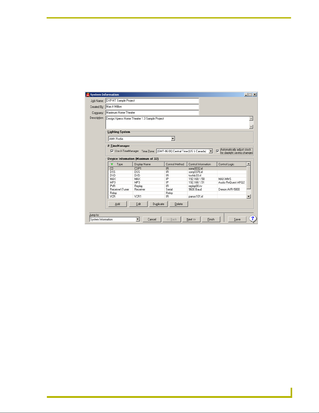
System Information dialog
The first dialog in the Project Wizard is the System Information dialog (FIG. 1). This dialog
contains the information used by Design XPress - Home Theater (DXP-HT) to create and program
the control system.
Double-click on any device in the list to access the Device Configuration dialog, containing all
control information associated with the device.
FIG. 1 System Information dialog
The following list describes the items in the System Information dialog:
Note that since the Job Name, Created By and Company names are also used in the NetLinx
program, the characters that you are allowed to use are A-Z, a-z, 0-9, - and _. These fields are all
limited to 40 characters.
• Job Name: Enter the name of the project here. Each new project should be given a
unique Job Name and Description.
• Created By: This field is pre-populated, if this information was entered in the User Infor-
mation dialog. Otherwise, enter or edit the name of the project author here.
• Company: This field is also pre-populated, if this information was entered in the User
Information dialog. Otherwise, enter or edit the name of the company here.
• Description: Enter a description of the project here (8190 characters maximum). Any
alphanumeric character (including punctuation) can be used. Each new
project should be given a unique Job Name and Description.
XP-HT v1.3 - Programmer’s Guide
21
Page 30

Using the DXP-HT Project Wizard
• Lighting System: Click the down-arrow to open a drop-down list of lighting systems sup-
• i!- TimeManager: The i!-TimeManager section allows you to enable the i!-TimeManager
• Device Information
(Maximum of 32):
ported by DXP-HT. Select the lighting system you are using, or select No
Lighting Control (at the top of the list) if your project does not include any
lighting control.
Additional fields may be displayed depending upon the device configuration
requirements of the selected lighting system. For example, the LiteTouch
5000LC displays a combo box to select the baud rate for communications
with the LiteTouch controller. However, the AMX Radia system does not
have a Baud Rate combo box because it communicates via AXlink.
In addition to selecting the lighting system, DXP-HT will automatically
select the default baud rate if applicable. You can manually set the baud
rate for non-standard systems.
remote time server application, which updates the time information on any
communicating Master running the i!-TimeManager code.
1. Click the Use i!-TimeManager radio button to select a time zone and
apply Daylight Savings Time rules.
2. Select a time zone from the Time Zone drop-down list.
3. Click the Automatically adjust clock for daylight saving changes
radio button to allow the application to automatically adjust the time for
daylight savings.
This table displays a list of all controlled devices currently in this system
(maximum of 32). The devices defined here determine the dialogs and
information required by the rest of the Project Wizard.
Every device that will be controlled by the DXP-HT system needs to be
defined within the Device Information list. The setup and configuration of
the devices is handled on subsequent dialogs in the Project Wizard, but
each device will be listed along with its Display Name, Control Method and
Control Logic, if any.
Note: In addition, any uncontrolled devices, such as computers, that have a
switcher input or output should be defined in the Device Information list.
The Device Information List can be sorted by clicking on the column's
header cell. Clicking on the header cell will toggle between sorting in
ascending or descending order.
Click the Add button to add a device to the list, via the Source Configuration dialog.
Select a device from the list and click the Edit button to edit the control information
associated with that device. You can also edit a device by double clicking on a device.
Click the Duplicate button to duplicate a selected source and its current settings.
Select a device from the list and click the Delete button to delete that device from the list
and remove it from the project.
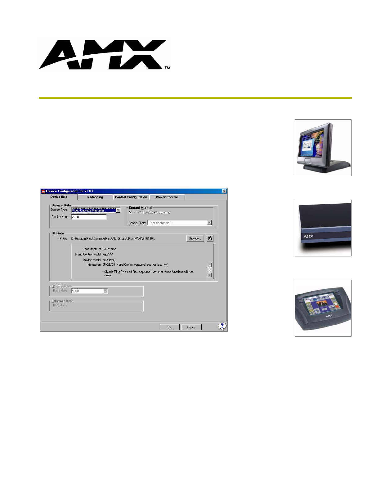
Adding a Device to the Project
To add a device to your system, click the Add button in the System Information dialog. This opens
the Device Configuration dialog - Device Data tab.
In the Source Configuration dialog (Source Data tab):
1. Select the type of equipment you are adding from the Source Type drop-down list.
2. Enter a name for the device in the Display Name field. This is the name for the device that will
appear on the touch panel.
3. If the device is a CD or DVD player, specify the size of the disc changer (if applicable; by
default this field is set to 1).
22
DXP-HT v1.3 - Programmer’s Guide
Page 31

Using the DXP-HT Project Wizard
4. Use the radio buttons to select the Control Method associated with the new device (IR, Serial
or IP).
If IR is selected, you must locate the associated IRL file by using the Browse button from
the IR Data section. If you are using Serial as a Control Method, choose the device from
the Control Logic drop-down list.
The control method(s) available for selection depend on the device type specified.
Adding IR-Controlled Devices to the Project
To add a device to your system, click the Add button in the System Information dialog. This opens
the Device Configuration dialog - Device Data tab.
In the Source Configuration dialog (Source Data tab):
1. Select the type of equipment you are adding from the Source Type drop-down list.
2. Enter a name for the device in the Display Name field. This is the name for the device that will
appear on the touch panel.
3. If the device is a CD or DVD player, specify the size of the disc changer (if applicable; by
default this field is set to 1).
4. Use the radio buttons to select IR as the Control Method associated with the new device.
5. Associate an IR code file (*IRL) to the new device:
Click the Browse button to locate and select the appropriate IR file via the Select IR File
dialog.
Click the Search button (the binoculars icon) to search for the appropriate IR file, via the
Search for IR File dialog.
6. Once an IR file has been selected, note that the Manufacturer, Hand Control Model #, Device
Model # and Info fields are automatically updated to show any property-level file information
that was associated with the selected IR file when it was created.
7. Use the up and down arrows to adjust the IR pulse time (in .10-second increments) in the IR
Pulse field. The default setting is .5 seconds.
8. Open the IR Mapping tab of the Device Configuration dialog to assign IR function/channels to
Touch Panel functions:
a. Click the Auto Assign button to automatically assign IR Functions to Touch Panel
functions. In most cases, this should be sufficient. However, you can use the IR Mapping
tab to manually assign IR Functions to Touch Panel functions:
b. Select the Touch Panel function that you want to associate an IR Function to (in the right-
hand table).
c. Select the IR Function that you want to assign to the selected Touch Panel function (in the
left-hand table), and click the right arrows button to copy the selected IR Function to the
selected Touch Panel function.
XP-HT v1.3 - Programmer’s Guide
23
Page 32

Using the DXP-HT Project Wizard
Inversely, you can manually remove any IR functions from Touch Panel functions by selecting
a Touch Panel function (from the right-hand table), and click the left-arrows button.
When adding multiple devices of similar type to a Project, in some cases the devices
could have very different requirements in terms of functionality and associated Touch
Panel pages/buttons. For example you could set up a high-end model DVD player
with full IR functionality and a second one with only basic DVD transport control. The
Design XPress - Home Theater TPD pages for both devices will show the same
number of buttons, but many buttons for the second DVD will not work, because
functions weren't mapped to them.
Try to keep the number of functions for multiple same-type devices as close as
possible, for ease-of-use for the end user.
Adding Serial-Controlled Devices to the Project
To add a serial (RS-232)-controlled device to your system, click the Add button in the System
Information dialog. This opens the Device Configuration dialog - Device Data tab.
Be aware that the target NetLinx Master device (being used by the project) must be able to support
the number of serial devices being added to the system. For example, if four serial devices were
added to a System (where they directly connect to the Master), then the NI-700 is not a valid choice
because it only supports 2 serial connections. In this case. The NI-700 option is disabled during the
final project build process (using the Finish button).
However, if the serial devices were communicating to the Master via external serial interfaces such
as an AXB-232++, an NI-700 could be used. If the cable run distance from the COM port and the
external Serial device is too far, it is recommended that you assign a different COM port within the
Use remote serial interface drop-down list. If the cable run distance from the serial interface and
the external Serial device is close enough, you can use both ports on the serial interface.
These external Serial devices communicate via the external serial interfaces to an AXB-232++ and
are not directly communicating with a Master (NI-700); therefore, these interfaces do not consume
Serial communication ports on the Master. This device configuration can function with an NI-700
when all of the Serial communications are routed from the external serial interfaces through an
AXB-232++ RS232/422/485.
The AXB-232++ provides a way to bridge the gap between an NI-700 (with no ICSNet port) and
the external serial interfaces, but when working with the RS232/422/485 device, the end-user must
use the AXlink device IDs generated by DXP-HT.
This device ID information is saved along with the COM port assignments and if another Master
device is later chosen as the target Master, the COM port assignments will be reflected within the
project report and used by the project wizard.
To add a serial-controlled device to your system, click the Add button in the System Information
dialog. This opens the Device Configuration dialog - Device Data tab:
1. Select the type of equipment you are adding from the Source Type drop-down list.
24
2. Enter a name for the device in the Display Name field. This is the name for the device that will
appear on the touch panel.
3. Use the radio buttons to select Serial as the Control Method associated with the new device.
DXP-HT v1.3 - Programmer’s Guide
Page 33

Using the DXP-HT Project Wizard
When you select a desired CD/DVD model from the Control Logic field, the changer size
is automatically filled and is read-only.
The control method(s) available for selection depend on the device type specified.
4. Select the required baud rate for the serial device from the Baud Rate drop-down list. (if
applicable).
Adding IP-Controlled Devices to the Project
To add a device to your system, click the Add button in the System Information dialog. This opens
the Device Configuration dialog - Device Data tab.
In the Source Configuration dialog (Source Data tab):
1. Select the type of equipment you are adding from the Source Type drop-down list.
2. Enter a name for the device in the Display Name field. This is the name for the device that will
appear on the touch panel.
3. If the device is a Compact Disc Player or Digital Video Disc player, specify the size of the disc
changer (if applicable; by default this field is set to 1).
4. Use the radio buttons to select IP as the Control Method associated with the new device.
The control method(s) available for selection depend on the device type specified.
5. Enter the IP Address of the ethernet-controlled device.
Adding a MAX-IMS or MMS Server to the System
To add a MAX-IMS or MAX-MMS server to your system, Click the Add button in the System
Information dialog to open the Device Configuration dialog - Device Data tab.
1. Select AMX MAX from the Source Type drop-down list.
2. Enter a name for the device in the Display Name field. This is the name for the device that will
appear on the touch panel.
3. Select the Control Logic, based on which type of MAX server you are adding (either IMS or
MMS).
4. In the IP Data field, enter the MAX server's IP Address.
5. Select an Output Zone number, which must be unique per each server used in a project. For
example, if a system has two MMS servers, each MMS could have an Output Zone 1.
The valid ranges are:
MAX-IMS = 1 to 8
MAX-MMS = 1 to 25
Each device IP Address must be unique, with only one exception: MAX servers can
use one IP with multiple output zones per display name entry. For example, a MAXIMS assigned to IP Address 1.1.1.1 - Zone 1 can exist in the same project as another
MAX-IMS assigned to IP Address 1.1.1.1 - Zone 2. But you cannot assign two MAX
servers with the same IP Address and Output Zone (you will receive an error
message).
XP-HT v1.3 - Programmer’s Guide
25
Page 34

Using the DXP-HT Project Wizard
Duplicating a Source Device
DXP-HT supports duplicating existing source devices and their settings via the Duplicate button
on the System Information dialog. Use the Duplicate feature to make a copy of the currently
selected device, to allow for quick configuration for systems with multiple identical devices.
The Duplicate button is only enabled once a device (DVD, CDP, MP3 player etc.) is
added to the project, and only if DXP-HT supports multiple devices of that type.
Receivers cannot be duplicated. If you select a receiver from the Device Information table
(of the System Information dialog), the Duplicate button is disabled.
The program will not allow you exceed the maximum number of eight display devices
(two). If you have two or more display devices (TV, Plasma or Projector) listed, the
Duplicate button is disabled.
To duplicate an existing source device and its current settings:
1. Select a source device in the System Information dialog.
2. Click the Duplicate button
3. A duplicate of the selected source device is added to the Device Information table in the row
below the selection.
4. When a source is duplicated its "Display Name" will be truncated to 13 characters and "_00"
added, where 00 is next sequential number for that display name. For example, if you
duplicated a source with the Device Name "DSS", the resulting duplicate source would have
the Device Name "DSS_1".
Device Considerations when using New Features
When working with several of the new features available in DXP-HT version 1.3, note the
following special device considerations:
If the i!-Weather application is installed on a Master without a weather account, only
AMX-related locations are viewable within the i!-Weather page on the touch panel. To
gain access to any zip code's weather information, you must purchase a subscription from
AMX.
To obtain this subscription, you all need the serial number of your target Master. This
appears on the i!-Weather setup page on the panel (once the project is loaded). Another
method of obtaining the Master's serial number is by going into a Terminal session and
typing 'show device'.
You can define your own time server by opening the Main.axs file, scrolling to the i!-
TimeManager section, and filling in the time server variable with the target IP Address.
By default, the time information from the atomic clock in Boulder, Colorado is used.
26
When using G4 Computer Control, it is important to understand that the DXP-HT
application does not setup the applications on the USB stick for you. It is necessary to
configure the configCC and amxCC applications (regarding the Master and touch
panels) prior to compiling the DXP-HT project. Any Master code alterations and
configCC field entries must be done prior to launching the amxCC executable.
DXP-HT v1.3 - Programmer’s Guide
Page 35

Using the DXP-HT Project Wizard
Device Configuration dialog
The Device Configuration dialog is used to add or edit devices in the Device Information List. Use
the options in this dialog to select the device type, the display name, control method and other
information specific to the control method.
Click the Add button in the System Information dialog to open the Device Configuration
dialog to configure a new device.
Select a Device from the Device Information table (in the System Information dialog) and
click the Edit command button (or double-click on a device in the table) to open the
Device Configuration dialog.
When a device using IR Control is selected for editing, the Device Configuration dialog divides out
into four tabs:
When a non- IR controlled device is selected, only the Device Data tab is displayed.
Device Data: Contains fields that specify the device type, device display name, control
method and control data for a controlled device in the project.
IR Mapping: The options in this tab help to insure that the button you press on the touch
panel does what you expect. This tab is where you specify the IR Mapping for the
selected device.
Control Configuration: The options in this tab are used to configure the AMX IR port to
properly transmit the IR signal to the AV equipment. This tab requires that you know how
your equipment operates.
Note that the Control Configuration tab is only applicable if:
The selected device is IR-controlled (IR was selected as the Control Method in the
Device Data tab).
An IR file has been associated with the device (via the IR Data options in the Device
Data tab).
Power Control: The options in this tab allow you to configure power control for the AV
equipment. This tab requires that you know how your equipment operates.
Device Configuration dialog - Device Data tab
The options in the Device Data tab of the Device Configuration dialog allow you to associate a
control method to a new device in the system. The options in this tab include:
Device Data: When defining a source you must first define the type of the source. The
Source Type determines what pages are added to the touch panel file and what control
functions are assigned to the device. The Display Name is used with the touch panel
menus to reference the device. Each Display name should be unique to differentiate the
devices in the wizard and on the touch panel.
XP-HT v1.3 - Programmer’s Guide
27
Page 36

Using the DXP-HT Project Wizard
FIG. 2 Device Configuration dialog (Device Data tab)
There are several devices that have device specific options that become visible when the
device is selected.
• Source Type: Click the down-arrow to open a drop-down list of available device
Note: The User Defined Input and AUX/PC options are intended for use with auxiliary devices
that can be accessed, but not controlled by the DXP-HT system (i.e. video game consoles,
turntables, etc). If you select User Defined Input or AUX/PC as the Source Type, the Control
Method and Data options are disabled, since the device is not controlled by the system.
Either of these options will perform the same function; they allow for the switching of an
uncontrolled device. The AUX/PC option provides a menu button for the device, and a touch
panel page alerting the user that the current device is uncontrollable. Selecting User Defined
Input allows the switching to occur without the menu item and a touch panel page.
Note: DXP-HT v1.3 (or higher) supports G4 Computer Control, and i!-Weather as Source Types.
• Display Name: Enter the name that you want to appear on the Touch Panel for this
Note: If you are designing for a CV6 panel, limit the text characters to 10 characters to avoid text
overflow on the button.
•Changer Size: Enter the value of the disc capacity available from the DVD/CD
• Use Macro for Navigation
and Device Routing:
types (Compact Disc Player, Digital Satellite System, Digital Video
Disc Player, etc). Click to select the device type that matches the
device you are adding to the project.
device (15 characters max).
player (450 max). If using a Serial connection, this field is disabled.
This radio box option enables the use of macros for menu navigation and device routing for the selected device (within the Device
Data tab). By selecting this option, an entry is added to the Navigation and Routing Macros dialog. This entry can then be later
modified if necessary.
28
Control Method: The Control Methods section enables its options based upon the
selected Source Type. Many device types support IR, but some devices support Serial
(RS-232) or IP communications through different Control Logics.
DXP-HT v1.3 - Programmer’s Guide
Page 37

Using the DXP-HT Project Wizard
Control Logics are specific device behaviors that have been programmed into the NetLinx Code
either through Modules, System Calls or Include files. A list of the applicable Control Logics will
appear in the Control Logics combo box.
• Control Method radio buttons: Use the radio buttons to specify the method of control for this
device (IR, Serial or IP). This selection determines the other
options that are enabled in this tab.
Note: If a Video Display device (such as a Projector/Plasma and TV) is chosen to be controlled
via Serial (RS-232), two new fields become available within the Device Data section: the Use
remote serial interface option, and a port selection drop-down list. Place a checkmark in the
Use remote serial interface checkbox to indicate that you are using an external serial interface
(leave it unchecked to use a Serial port on the Master).
If this option is checked, you can choose which port on the COM card to use by choosing a port
from the drop-down list. This was implemented to communicate to some display devices that are
not located near the Master.
• Control Logic: Select a type of control logic from this drop-down list, if appli-
IR Data: The IR Data section allows you to configure a number of settings for IR
cable.
controlled devices. The IR File field displays the currently selected IR file (read-only).
You can select an IR file using the Browse or Search buttons.
If IR is selected, you must locate the associated IRL file by using the Browse or
Search buttons. If you are using Serial as a Control Method, choose the device from
the Control Logic drop-down list.
The Search button (binoculars icon) brings up the Search for IR File dialog, which
allows you to search by Manufacturer, Hand Control Model # or Device Model #.
Once an IR file has been selected the information about the IR file is extracted and is
displayed in the text fields below the IR File area (at the bottom of the Search for IR Files
dialog).
IR File: Use the Browse and/or Search buttons to locate and select the IR file to be
associated with this IR-controlled device.
All options in the IR Data section of this tab are disabled if Serial or IP was selected
as the Control Method.
Manufacturer, Hand Control Model #, Device Model #, Info: These read-only
fields are populated with information, once an IR file has been associated with this
device. When any IR-controlled device is selected, two additional tabs become
available on this dialog:
• IR Mapping
• Control Configuration
• Power Control
Serial Data: Click the down-arrow to open a drop-down list of all supported baud rates
for serial control. Click to select the appropriate baud rate for the serial-controlled device.
This field is only enabled if Serial was selected as the Control Method, and if the device
does not have a default baud rate setting.
XP-HT v1.3 - Programmer’s Guide
29
Page 38

Using the DXP-HT Project Wizard
IP Data: For IP-controlled devices, enter the IP address of the device in the IP Address
field. The IP Port number is set within the Control Method and is not accessible. This
field is only enabled if IP was selected as the Control Method.
Each device IP Address must be unique, with only one exception: MAX servers can
use one IP with multiple output zones per display name entry. For example, a MAXIMS assigned to IP Address 1.1.1.1 - Zone 1 can exist in the same project as another
MAX-IMS assigned to IP Address 1.1.1.1 - Zone 2. But you cannot assign two MAX
servers with the same IP Address and Output Zone (you will receive an error
message).
Device Configuration dialog - IR Mapping tab
The options in the IR Mapping tab (FIG. 3) help to insure that the button you press on the touch
panel does what you expect. IR files, especially custom IR files, do not always use the same
channel numbers for the same IR functions. As a result, you must map each IR function for each IR
device in the system. If irregular functions occur in the finished system, it is a good idea to revisit
the IR mapping.
30
FIG. 3 Device Configuration dialog - IR Mapping tab
It is also important to note that changing the IR mapping will affect subsequent configuration
screens. This is especially true for the Receiver's IR mapping, since the Receiver functions play
such a integral role in system operations.
The IR Mapping tab is divided into two main areas: IR File Functions and the Program Functions.
The IR Function List is on the left side of the window. The IR file selected on the Device
Data tab is opened and all functions and their associated names and channel numbers are
listed.
DXP-HT v1.3 - Programmer’s Guide
Page 39

Using the DXP-HT Project Wizard
The Program Function List is on the right side of the screen. The Program Function List
is populated with the supported functions for the Device Type selected on the Device
Data tab.
Mapping a Function
1. Click on the desired IR function on the IR Function List and click on the associated function in
the Program Function List.
2. Then, click on the button with the three right facing arrows, ">>>", and the IR Function Name
and the Channel are copied across to the Program Function List.
Removing a Mapped Function
Click on the button with the three left facing arrows, "<<<", and the IR Function Name will be
deleted and the Channel will be returned to its default.
The four command buttons across the bottom of the window are used to speed up the IR mapping
process:
Un-Map All - Returns all functions in the Program Function List to their default settings
and clears all IR Function Names.
Auto Assign - Pairs matching Channel numbers on the IR Function List and the Program
Function List and copies across the IR Function Names.
Un-Map Current Selection - Removes the IR Function Name for the selected item in the
Program Function List, and resets the channel to the default channel number.
Function Not Used - Sets the IR Function Name to "Not Used" and zeros the channel
number for the item selected in the Program Function List. Any IR functions that are
either labeled as "Not Used", or that are unmapped (left with the default value of zero)
will not appear anywhere in the functions list or anywhere else, since they are considered
to be unused by the system.
The OK button saves the IR Mapping and returns to the System Information Page.
The Cancel button discards all changes and returns to the System Information Page.
When adding multiple devices of similar type to a Project, in some cases the devices
could have very different requirements in terms of functionality and the associated
Touch Panel pages/buttons. For example you could set up a high-end model DVD
player with full IR functionality and a second one with only basic DVD with transport
control. The Design XPress - Home Theater TPD pages for both devices will show
the same number of buttons, but many buttons for the second DVD will not work,
because functions weren't mapped to them.
Try to keep the number of functions for multiple same-type devices as close as
possible, for ease-of-use for the end user.
XP-HT v1.3 - Programmer’s Guide
31
Page 40

Using the DXP-HT Project Wizard
Device Configuration dialog - Control Configuration tab
The options in the Control Configuration tab (FIG. 4) allow you to configure the AMX IR port to
properly transmit the IR signal to the AV equipment. This tab requires that you know how your
equipment operates.
FIG. 4 Device Configuration dialog - Control Configuration tab
IR Timing Parameters (1/10 second) - Sets the IR pulse times and the time gap between
pulses. The default time is .5 seconds. Occasionally, this pulse time is too long and results
in two commands being sent. This is most evident on numeric keypads and menu cursor
controls. Use the up/down arrows to adjust the values, or enter new values directly into
the text fields (range = 0 - 255, in 1/10 second increments).
IR Pulse Time - the length of time the IR signal is on and is being transmitted
(CTON).
Time Gap Between IR Pulses - the length of time between IR pulses. This is
usually used only in macro functions (CTOF).
Tune Using XCH Command - XCH Send_Commands are used to recall station presets
for the TV Tuner, VCR and DSS. Different manufacturers require the channel numbers to
be entered differently. Select the mode that matches your equipment. When this option is
selected, the following XCH Modes are available. Select the mode you want to use with
this device:
• Mode 0 The resulting IR for the Send_Command ’XCH-3’ would be: 3-Enter.
• Mode 1 The resulting IR for the Send_Command ’XCH-3’ would be: 0-0-3-Enter.
• Mode 2 The resulting IR for the Send_Command ’XCH-3’ would be: 0-0-3.
• Mode 3 The resulting IR for the Send_Command ’XCH-3’ would be: 0-3.
32
DXP-HT v1.3 - Programmer’s Guide
Page 41

Using the DXP-HT Project Wizard
• Mode 4 Mode 4 should only be used for channels 0-199, and sends the same IR sequences
Stack Pulse Parameters - If the Tune Using XCH Command option is de-selected, the
as the CH command.
Stack Pulse Parameters options become available. The Stack Pulse option mimics the
XCH commands, but uses IR pulses instead of sending commands.
Click the up/down arrows to adjust the number of digits to use when tuning the
device (or the total number of channel digits - whichever is larger). The default
setting is 3 digits.
Enable the Send Enter option to always send an Enter command with each stacked
pulse.
IR Carrier - Some devices (i.e. Sony Control-S devices) use a wired IR signal, instead of
using an IR emitter. In some cases, the signal is the same as is transmitted by the IR
emitter, but it does not transmit a carrier signal. This check box will turn on or off the
carrier signal. The default setting is On.
Wired IR - Enable this option if the wired IR device requires Mode Serial signals.
Device Configuration dialog - Power Control tab
The options in the Power Control tab (FIG. 5) allow you to configure power control for the AV
equipment. This tab requires that you know how your equipment operates.
FIG. 5 Device Configuration dialog - Power Control tab
Device Supports Discrete On/Off - If you have mapped Discrete On/Off functions for
this device, you can select to enable support of Discrete On/Off.
XP-HT v1.3 - Programmer’s Guide
33
Page 42

Using the DXP-HT Project Wizard
Govern Power - This option enables governing power to the device, which means that
the System constantly monitors power to the device (for use with power sensors) rather
than simply toggling power On/Off.
Device/Power Feedback - This option enables the display of power status of the device
on the touch panel. If this option is enabled, use the radio buttons to specify a Power
Sensing Method, based on the type of power sensor being used with the device (PSS2,
VSS2 or TVS).
Power Sensing Method - Activated by enabling the Govern Power option (described
above). Use the radio button to select the method of power sensing being used. This
available power sensors include: PCS2 (Dual Power Current Sensor), VSS2 (Video Sync
Sensor), and TVS (TV Sensor).
IR Timing Parameters - Use the up/down arrows to adjust the time gap between Po wer
On and Pow e r Off IR pulses, in 1/10 second increments (default = 50).
Working with MAX Servers
DXP-HT v1.3 (or higher) supports MAX-MMS and MAX-IMS media servers. DXP-HT treats
these devices essentially the same as any other IP-controlled device (such as MP3 players). There
are just a few points to understand in order to add MAX servers to a DXP-HT project:
The MAX-MMS and MAX-IMS servers are IP-control only, and they must be used with
AMX G4 touch panels (see Supported Touch Panels).
Each MAX-AVM A/V Module connected to a MAX-MMS server must each be set to a
unique zone number (per server).
If multiple MAX-MMS or MAX-IMS servers are used in a project, each server must have
its own unique IP Address.
Each device IP Address must be unique, with only one exception: MAX servers can
use one IP with multiple output zones per display name entry. For example, a MAXIMS assigned to IP Address 1.1.1.1 - Zone 1 can exist in the same project as another
MAX-IMS assigned to IP Address 1.1.1.1 - Zone 2. But you cannot assign two MAX
servers with the same IP Address and Output Zone (you will receive an error
message).
Refer to the MAX-MMS and MAX-IMS Installation Guides (available online at www.amx.com)
for details.
34
DXP-HT v1.3 - Programmer’s Guide
Page 43

Using the DXP-HT Project Wizard
Which Screens? dialog
The Which Screens? dialog (FIG. 6) is available for selection in the Jump To drop-down, once the
project has been finished and re-opened.
Use this dialog to specify which Project Wizard dialogs to include in the Jump To list, to further
simplify using the application. By default, all dialogs are selected. Click the checkboxes to disable
any dialogs that you don't intend to revisit for editing.
FIG. 6 Which Screens? dialog
Once you have made your selections, click Back or Next to close this dialog.
Note that you can't disable the System Information dialog.
XP-HT v1.3 - Programmer’s Guide
35
Page 44

Using the DXP-HT Project Wizard
Audio/Video Inputs dialog
The Audio/Video Inputs dialog creates the association between the Devices defined on the System
Information dialog, the Inputs defined for the receiver, and the physical input connectors on the
back of the receiver. Each source Device must be associated with a Physical Label, an Input Type
and the IR or Control Logic command required to switch the receiver.
Use the Audio/Video Input dialog to label the audio and video inputs on the primary receiver in the
system.
FIG. 7 Audio/Video Inputs dialog
This dialog contains the Inputs to Receiver table, which consists of several columns. The Input
Type , Physical Label, Input Command (and Display Device Input, if applicable) fields can be edited
in the combo boxes in the bottom half of this dialog:
• Display Name: This column is a list of all source devices currently in the system.
• Physical Label: This column indicates the physical label (on the receiver) that is associated with the device, as specified in the Physical Label text field in the
lower half of this dialog. The Physical Label is for installation purposes
only and is intended for the installer's reference in the generated report
file. You can edit this information via the Physical Label text box at the
bottom of this dialog.
• Input Type: This column differentiates audio-only inputs from Audio/Video Inputs.
This is important when using a RS-232 Control Logic.
• Display Device Input: For A/V inputs only, this column indicates the display device input, as
specified in the Display Device drop-down at the bottom of this dialog.
The combo boxes in the lower half of this dialog allow you to populate the Inputs to Receiver table:
• Display Name: This read-only field indicates the Display Name assigned to the device in
the System Information dialog.
36
DXP-HT v1.3 - Programmer’s Guide
Page 45

Using the DXP-HT Project Wizard
• Input Type: This field differentiates audio-only inputs from A/V inputs. Select the
• ·Physical Label: Type the physical label (as it appears on the back of the receiver) that you
• Display Device: This drop-down list is only available if you have selected an A/V input.
Click Apply to apply any changes made to the selected device.
Click Clear to clear the Input Type, Physical Label, Select Command and Display Device
appropriate input from the drop-down list (Audio Only, Component, Composite, HD Component, HD RGB or S-Video).
Note: If you select any Input Type other than Audio Only, an additional
drop-down is displayed at the bottom of this dialog - Display Device (see
below).
want to associate with the selected input device.
This list contains all of the IR commands listed for the device in the IR
Mapping tab of the Device Configuration dialog.
(if applicable) information for the selected device.
The Control Method and Source Type selected (in the Device Data tab of the
Device Configuration dialog) determine the amount of information available to DXPHT. For example, IR devices provide no information about inputs, so for IR devices all
possible input functions are provided (to be mapped). For RS-232 devices, as part of
the nature of the control method, the names (and types) of the inputs are known.
Surround Sound Presets dialog
The Surround Sounds Presets dialog sets up the Surround Sound Modes screen on the touch panel.
The Surround Sound Modes for Receiver table lists all of the declared Surround Sound Modes.
The columns can be sorted by the display Order, or the Display Name.
FIG. 8 Surround Sound Presets dialog
The text entered into the Display Name text box is used on the buttons for the touch panel's
Surround Sound Mode screen.
XP-HT v1.3 - Programmer’s Guide
37
Page 46

Using the DXP-HT Project Wizard
The Add button will add a new surround mode to the top of the list. Note that you can
only add new modes if IR has been specified as the receiver's Control Method (as
indicated in the System Information dialog).
The Delete button deletes the selected surround mode from the list.
Click the Insert button to insert a new mode after the currently selected mode.
Click the Apply button to apply any changes that have been made to the selected mode.
Click Clear to reset all surround modes and display names to their default settings. This
option also restores any modes that have deleted.
The order of the Surround Sound Modes can be modified by using the Up and Down arrows to the
right of the Surround Sound Modes list. Clicking on a defined list item selects that item for editing.
Adding a Surround Sound Mode
1. Type the text that will appear on the Touch Panel button for this preset in the Display Name
text box.
2. Select a command from the Command drop-down list.
38
DXP-HT v1.3 - Programmer’s Guide
Page 47

Using the DXP-HT Project Wizard
Lighting Presets dialog
The Lighting Presets dialog sets up the available presets for the Lighting system selected on the
System information page. There is a maximum of nine presets available. DXP-HT does not allow
for individual zone control or the setting of presets, only the recall of existing presets.
FIG. 9 Lighting Presets dialog
The defined lighting presets appear in the Lighting Presets table. You can sort the presets by
clicking on the header cell for any of the columns. Clicking the header cell toggles sorting to either
ascending or descending order.
The defined lighting presets appear in the Lighting Presets table. You can sort the presets by
clicking on the header cell for any of the columns. Clicking the header cell toggles sorting to either
ascending or descending order.
Adding a New Lighting Preset to the bottom of the Lighting Presets list:
Enter a new Preset Name, Address and Button Number, and click the Add button to add a new
preset to the bottom of the list.
Deleting a Lighting Preset
Select a Preset in the list and click the Delete button.
Inserting a New Lighting Preset into Lighting Presets list:
Select a preset in the list, and click the Insert button to add the new preset to the list, directly above
the selection.
Editing a Lighting Preset:
Click on a cell within the Lighting Presets table to select the preset for editing. Use the text boxes at
the bottom of this dialog to edit the selected presets Name, Address and Button Number:
XP-HT v1.3 - Programmer’s Guide
39
Page 48

Using the DXP-HT Project Wizard
The identifier entered into the Preset Name text box is the name that will be displayed on
the touch panel. No duplicates allowed (8 characters maximum).
The Address field correspond to either the lighting controller address and the preset
number (as with AMX Radia), or the address of the keypad and the keypad button that
will be emulated (as with the LiteTouch controller).
For the AMX ALD-D48, the address is the 7-digit ID number of the ALD-D48 Device
Server.
For the AMX Radia the address is the AXlink address of the Radia MC.
The only valid keypad address characters are 0-9, A-F, and : (colon). For reference, here
are the formats for the various supported lighting systems:
Lighting Controller Address Format DXP-HT Example
• AMX ALD-D48 The Address value is fixed at a value of one
• AMX Radia AXlink Device ID (1-255)The Address is the
• Clipsal C-Bus Group Address:Network Address (using a hex
• DynaLite DynaLite area (positive integer) 18
• Lehigh DX2 Lehigh area (1 - 16) 1
• Lutron GRAFIK Eye Master (positive integer) 17
• Lutron Homeworks
Interactive
• Lutron RadioRA Keypad Address (positive integer)
• LiteTouch 5000LC Keypad Address (3 nibble hex value A3E
• Tridonic DALI Tridonic group address (0 -15) 0
• Vantage Qlink Master:Keypad (positive integers) 1:5
and is disabled. This value corresponds to the
Device ID of the keypad.
AXlink device ID of the Radia MC.
value and a local network address)
Processor:Link:Keypad (positive integers) 1:4:9
Note: keypad address 12 is reserved as the
RS-232 RadioRA interface. This interface is a
virtual keypad, and does not contain any buttons.
1 (read-only)
96
A1:D4
12
40
For the AMX ALD-D48, the Address field value is fixed at a value of one (1) and is
read-only. This value corresponds to the Device ID of the keypad.
Click the Apply button after editing a preset to apply the changes.
The Button # refers to the button number or scene number the DXP-HT system is to
emulate when communicating to the lighting system.
For AMX Radia, the button # is the scene number to be recalled when this scene is
selected on the touch panel.
For Clipsal C-Bus and Dynalite systems (used primarily outside the U.S.), the button #
consists of the button number plus the fade rate, separated by a semi colon. For example:
(C-Bus): K:P:[A4:E1]:75:8 indicates network $E1, group address $A4, go to 75%
at 8-second fade rate.
DXP-HT v1.3 - Programmer’s Guide
Page 49

Using the DXP-HT Project Wizard
(Dynalite): K:P:[14]:12:25 indicates area #14, go to preset scene #12 at 25-second
fade rate.
The Clear button clears the Preset Name, Address and Button Number information for a
selected preset.
Resorting the Presets List:
Select a Preset and click the up/down arrows (to the right of the Lighting Presets table) to rearrange
the order of the list.
Note for ALD-D48 Lighting Systems
The ALD-D48 is not controlled by Send Commands, so each button on the touch panel or keypad
corresponds to a specific dimmer.
For instructions on developing NetLinx code to program scenes for the D48, refer to Tech Note #
TN 543, available via www.amx.com (Dealers > Tech Center > Tech Notes).
For detailed configuration information on the ALD-D48, refer to the ALD-D48 Network Lighting
Solution Instruction Manual, also available via www.amx.com (Dealers > Tech Center > Tech Docs
> Instruction Manuals).
Note for Radia Lighting Systems
On Radia lighting systems, channels 1-128 represent Radia lighting presets 1-128. If a channel is
on, then the corresponding preset is on. However, on startup NetLinx resets all channels to 0 (OFF).
Radia does not report the status of its channels when the master comes up, and consequently the
software believes the state of all of the presets is OFF. Therefore, until a preset changes in the
system, the channel states are not reported.
It is important to have the Lighting Preset information prior to finishing the project.
Enter a new Preset Name, Address and Button Number, and click the Add button to add a
new preset to the bottom of the list.
Select a Preset in the list and click the Delete button to delete that preset from the list.
The Insert button inserts a new preset at the order number of the currently selected
preset.
Click the Apply button after editing a preset to apply the changes.
The Clear button clears the Preset Name, Address and Button Number information for a
selected preset.
XP-HT v1.3 - Programmer’s Guide
41
Page 50

Using the DXP-HT Project Wizard
Touch Panel Interfaces dialog
DXP-HT requires that at least one touch panel is defined within the system.
You can define up to 8 touch panels in the system
FIG. 10 Touch Panel Interfaces dialog
The Touch Panel Interfaces table can be sorted by clicking on any of the three column header cells
(Panel ID, Display Name and Type ). Clicking the header cells toggles between sorting the column
in ascending or descending order. Clicking on any of the cells within the list selects the touch panel
for editing.
The Panel ID is an arbitrary reference to the touch panel and is not the AXlink Device
ID. You can find the AXlink Device ID in the report generated by DXP-HT.
The Display Name is the reference to the touch panel that is used in the installation
report.
The Type determines which touch panel files get modified and added to the NetLinx
Studio Project. There are several supported panel types (see the Modero (G4) touch
panels section on page 5 and G3 touch panels section on page 6 for details).
To add a new Touch Panel Interface
1. Enter a name for the new panel in the Display Name field.
2. Select a panel type from the Panel Type drop-down list.
3. Click the Add button to add the newly configured panel.
42
DXP-HT v1.3 - Programmer’s Guide
Page 51

Using the DXP-HT Project Wizard
Use Picture Frame for Inactivity Page
Click this option to use the PictureFrame application as a screensaver when the touch panel
becomes inactive (this option tells the panel to launch the PictureFrame application from the target
PC rather than use the DXP-HT Logo page, when the panel times-out).
If this option is selected, you'll have to open the TP4 file created by the DXP-HT wizard, and
configure the dynamic image properties to pull images from the PC running the PictureFrame
application.
If the panel timeout is set to zero, the panel will never go to the Inactivity Page. Panel
Timeout is a setting that is made directly on the touch panel (via the Setup pages).
Use TakeNote
Click this option to enable TakeNote functionality within a pre-selected G4 Computer Control
(G4CC) page. Note that the Use i!-TakeNote option is disabled unless both of the following
conditions are met:
1. G4CC and/or AUX/PC must be defined as Source Types within the Device Configuration
dialog (Device Data tab) AND
2. A Modero panel must be added to the list of available panels. If both of these conditions are
met, the TakeNote! option box is selectable. If either of these conditions is not met, the radio
box is grayed-out.
By default, when you select the TakeNote option, from within the Touch Panel Interface dialog,
TakeNote becomes enabled within the G4CC panel page even before it is selected. To disable
TakeNote, you must navigate to the G4CC touch panel page, press the TakeNote button, and then
toggle the Annotation button (from within the TakeNote popup menu) to the Off state. To reestablish the TakeNote feature, return to the TakeNote popup menu and toggle the Annotation
button back to the On state.
To disable this feature, press the TakeNote button and navigate to the Annotation button (in the
toolbar popup on the upper-right of the G4CC page). Toggle this button off to de-activate TakeNote
and begin using Computer control.
Menu Style for All Touch Panels
Use these radio buttons to select the menu style to be displayed on all touch panels in the system.
Scrolling allows the user to scroll through the menu buttons using left and right-arrow buttons, and
Static displays all menu buttons with no scrolling involved.
Exclude from Navigation Menu
These options allow you to exclude these menu items (Source Types) from the menu (no buttons
with which to access these pages). This might be used of the developer doesn't want an end-user
accessing or altering settings for these sources. The sources which can be omitted are:
Display Button
Lights Button
Macros Button
XP-HT v1.3 - Programmer’s Guide
43
Page 52

Using the DXP-HT Project Wizard
Relay Button
All of these selections are dependent on these devices first being defined. For example, if no
lighting was previously defined, the Lights Button checkbox will be disabled.
Choose Touch Panel Theme dialog
The Choose Touch Panel Themes dialog allows you to select from a list of predefined layouts (or
themes) for your touch panels. All of the touch panels in the system will get the same settings
whether you are using a predefined or a custom theme.
44
FIG. 11 Choose Touch Panel Theme dialog
To select a theme, click on one of the theme names on the left side of the screen. A small-scale
preview image of the selected theme is displayed in this dialog. Click on the Preview button to see
a full size preview of the panel page.
If you select Custom (as the Theme), you will need to define the background, button colors and text
colors in the next three dialogs. If you are using a predefined theme, you will skip the next three
dialogs in the Project Wizard (Choose Touch Panel Background, Choose Touch Panel Buttons and
Choose Touch Panel Text Colors dialogs) and proceed directly to the Channel Preset Categories
dialog.
Click Next to continue creating a custom Touch Panel Theme.
Choosing Custom adds the Choose Touch Panel Background/Buttons/Text Color
screens to the Which Screens dialog and to the Jump To drop-down menu.
DXP-HT v1.3 - Programmer’s Guide
Page 53

Using the DXP-HT Project Wizard
Choose Touch Panel Background dialog
To select a background for your custom touch panel theme, click on one of the background names
in the list on the left side of the screen.
A small-scale preview image of the selected theme is displayed in this dialog.
Click on the Preview button to see a full size preview of the panel page.
FIG. 12 Choose Touch Panel Background dialog
Because of the amount of possible color combinations between backgrounds,
buttons and text, some combinations may be difficult to read on-screen. Be sure to
select color combinations with enough contrast (especially between text and
background color or image) that will be easy for the end-user to read. In some cases
you may need to make manual adjustments to ensure readability.
Choose Touch Panel Buttons dialog
To select a button style:
1. Expand the lists on the left side of the dialog and click on a button family style.
2. Click and drag a button color from the sample buttons across the top of the dialog.
3. Drag the sample button and drop it on the image that says Drag here to Update.
4. The button preview will update accordingly.
Choose Touch Panel Text Colors dialog
To select the touch panel text colors
1. Click and drag one of the colors from the color palette at the top of the dialog.
2. Drag and drop the color on the Text Off State or Text On State graphic, which says Drag here
to update.
XP-HT v1.3 - Programmer’s Guide
45
Page 54

Using the DXP-HT Project Wizard
FIG. 13 Choose Touch Panel Buttons dialog
FIG. 14 Choose Touch Panel Text Colors dialog
46
DXP-HT v1.3 - Programmer’s Guide
Page 55

Using the DXP-HT Project Wizard
Channel Preset Categories dialog
This dialog allows you to create up to 8 different preset categories. For example, you might create a
presets category for Sports channels, one for Movies channels, another for Children's channels, and
so on.
These categories appear within the bottom-right of the Channel Presets pages (such
as Channel Presets for DSS/TV/etc).
By default, there is one entry in the table: All Presets (Default). This system-defined preset category
cannot be edited or deleted.
FIG. 15 Channel Preset Categories dialog
To create new Preset Categories
1. Enter the name for the new Preset Category in the Display Name text field. This is the name
that will be displayed on the panel.
2. Click the Add button to add the new Preset Category to the bottom of the list.
3. Select a Preset Category in the list, type in a new Display Name, and click the Insert button to
insert the new Preset Category in the row above the selection. The Insert button is grayed-out if
the first row is selected.
XP-HT v1.3 - Programmer’s Guide
47
Page 56

Using the DXP-HT Project Wizard
To edit the Display Name for an existing Preset Category
1. Select one from the list, and enter the new name in the Display Name text field.
2. Click Apply to apply the change.
3. Use the up/down arrow buttons to change the order in which the Preset Category buttons will
occur on the touch panel.
To delete a Preset Category from the list, select one and click the Delete button.
Channel Preset dialogs
The Channel Preset dialogs are the same for any TV type channel preset, including TV tuners,
Cable TV tuners, DSS tuner, PVR tuners and VCR tuners.
Channel Presets dialogs are only included for devices that have been specified as
being "tuner capable". This is an option that must be manually selected, in the Device
Data tab of the Device Configuration dialog.
You can setup a maximum of 100 channel presets for each tuner. Each tuner carries it own set of
channel presets.
48
FIG. 16 Channel Preset dialog
The Channel Presets table can be sorted by clicking on any of the three column header
cells (Order, Preset Name, Uses Logo and Channel). Clicking the header cells toggles
between sorting the column in ascending or descending order. Clicking on any of the
cells within the list selects the channel for editing. The arrow buttons to the right of the
channel list will move the selected channel up or down in the list order.
DXP-HT v1.3 - Programmer’s Guide
Page 57

Using the DXP-HT Project Wizard
The Copy from: drop-down list allows you to copy a previously configured channel
preset to the current device. Click the down arrow to view the list, and select the channel
preset you want to copy into the Channel Presets table.
The Button Image drop-down list contains all of the preset channels in the Design
XPress -Home Theater wizard. When you select a button image, the image is previewed
to the left of the combo box. The wizard also automatically fills in the Preset Name field
with the same name as is in the Button Image field.
The Channel text box takes the channel number of the selected preset.
You can also define your own custom presets. If you select None as the button image, the
text placed in the Preset Name text box will be displayed on the touch panel button.
Relay Control dialog
DXP-HT can control up to three 3-relay-controlled devices. The devices can be any low voltage
relay device such as screens, projector lifts, drapes, or shades. To control the devices, you’ll need to
specify how the relays behave, how many relays are used in the control and what text needs to
appear on the touch panel buttons.
FIG. 17 Relay Control dialog
The Relay Control Declarations (maximum of 3) list at the top of the screen gives a summary of
the defined relay devices. The Relay Control Declarations list can be sorted by clicking on any of
the column header cells. Clicking on the header cells toggles between sorting in ascending and
descending order.
The Display Name text box is used to label the relay set on the touch panel.
XP-HT v1.3 - Programmer’s Guide
49
Page 58

Using the DXP-HT Project Wizard
The Control Logic drop-down menu allows you to select from 3 control type options: Latching,
Momentary and Pulse Type:
Latching relays remain on until another relay is selected.
Momentary relays will remain on as long as the touch button is being pressed.
Pulse Type relays will turn on for ½ second and then will automatically turn off.
Latching relays can use one, two or three relays to control a motor controller. DXP-HT always
reserves 3 relays, but you can configure it to match the control method for your motor controller.
For motor controllers that use a single relay, define two relays, but only connect one. For example,
if relay 1 is engaged the screen goes down, when it is disengaged the screen goes up. By defining
two relays, when the down button is selected, relay 1 is disengaged and relay 2 is engaged.
Engaging relays two would of course do nothing.
Momentary and Pulse Type relays require a minimum of 2 relays to be defined. Momentary relay
control would be needed if the motor controller does not have limit switches to stop the motors.
DXP-HT does not support timed closures in place of limit switches. Timed closure control has
historically been unreliable, and is therefore not supported.
Adding a Relay Control Definition to the list
Enter a name for the Relay in the Display Name text field. Then select a type of Control Logic.
Click the Add button to add the new Relay Control Definition to the bottom of the list.
Select a Relay Control Definition in the list and click the Insert button to insert the new
Relay Control Definition in the row above the selection.
Editing the Display Name for an existing Relay Control Definition
Select one from the list, and enter the new name in the Display Name text field. Click
Apply to apply the change.
Use the up/down arrow buttons to change the order in which the Relay Control Definition
buttons will occur on the touch panel.
Deleting a Relay Control Definition from the list
Select one and click the Delete button.
50
DXP-HT v1.3 - Programmer’s Guide
Page 59

Using the DXP-HT Project Wizard
Presets for Receiver AM/FM Tuner dialog
The Presets for Receiver AM/FM Tuner dialog sets up the radio presets for the receiver's AM/FM
tuner. You can setup and define as many presets as are present on the AM/FM tuner.
The presets must be discrete and must be on the same bank of presets. If you tuner has 3 sets of
presets (for example FM1, FM2, AM), and each set has 10 presets for a total of 30 presets, DXP-HT
would only be able to recall 10 presets. If your tuner uses Preset Up and Preset Down buttons,
DXP-HT would not be able to recall any presets using the AM/FM preset page.
FIG. 18 Presets for Receiver AM/FM Tuner dialog
Adding a Preset to the list
1. Enter a name for the Preset in the Display Name text field. Then assign a unique Preset
Number.
2. If the selected Tuner is IR-controlled (as specified in the Device Data tab of the Device
Configuration dialog), use the Preset Commands combo boxes to select up to three
commands per preset, to allow for different methods of recalling presets.
3. Click the Add button to add the new Preset to the bottom of the list.
4. Select a Preset in the list and click the Insert button to insert the new Preset in the row above
the selection.
Editing the Display Name for an Existing Preset
1. Select one from the list, and enter the new name in the Display Name text field. Click Apply to
apply the change.
2. Use the up/down arrow buttons to change the order in which the Preset buttons will occur on
the touch panel.
XP-HT v1.3 - Programmer’s Guide
51
Page 60

Using the DXP-HT Project Wizard
Deleting a Preset from the List
Select one and click the Delete button.
CD Titles dialog
The CD Titles dialog allows you to setup CD or DVD titles in multi-disc changers.
The number of title slots is determined by the changer size as set in the Device
Configuration dialog (Device Data tab). This dialog is only included in the Wizard if
the Project includes a CD or DVD player with at least a two-disc changer. A set of
tabs across the top of the dialog accommodate the disc capacity of the device (if
necessary). The tabs are numerated and each tab displays a set of 25 title slots. For
example, a CD or DVD player that holds 100 discs would use a set of four tabs to
allow access to slots 1-25, 26-50, 51-75 and 76-100.
Each title slot is a combo box that lists the CD titles setup in the CD Title Maintenance dialog
accessed through the main menu (Edit > CD Titles Maintenance). Next to each combo box is a
browse button that will extract the CD information from your CD-ROM drive and add it to the
combo box.
You can also manually type in new CD titles in the Manually add CD to data store section of this
dialog.
52
FIG. 19 CD Titles dialog
Anytime that you assign text to any type of preset button in your project, you must transfer the
button text that appears on the buttons in Design XPress to the NetLinx Master, in order to display
the button text on the panel(s) in the system. This holds true for CD and DVD Titles. Use File
Transfer Protocol (FTP) to transfer the files.
Refer to the Transferring CD/DVD Title Information to the Master via FTP section on page 61 for
details.
DXP-HT v1.3 - Programmer’s Guide
Page 61

Using the DXP-HT Project Wizard
Adding a new CD title:
Manually enter either Artist or Disc Title information to enable the Add button. Click the
Add button to add the new CD to the list.
Alternatively, you can select an existing CD title from the list, then edit the Artist and
Disc Title information, and click the Add as New button.
Editing CD Information
Select a CD title from the list to populate the Artist and Disc Title fields, where you can enter new
information as desired. Click the Update button to update that CD in the list.
Retrieving CD Information (from freedb.org)
1. Insert a CD into the CD player on your PC.
To prevent the CD from playing when it is inserted, hold down the shift key on the
keyboard while loading the CD.
2. Click the down-arrow (in the Setting to receive Disc data from freedb.org section of the dialog)
to view a list of available CD drives on your PC.
3. Select the drive that you placed the CD in, and click the Retrieve Disc Data from CD button.
If the disc has never been read before, DXP-HT will attempt to download the data from
freeDB.org.
Removing a CD Title
Select any CD in the list (Shift + click to select multiple CD Titles), and click the Delete button to
remove the CD(s) from the list.
The CD titles list must be downloaded using an FTP program. There are many of
these available on the web, most of them freeware. Connect to the master and
download all of the required files into the root directory (top-most directory) of the
master.
Using the CD Titles Maintenance dialog
Select Edit > CD Titles Maintenance to open the CD Titles Maintenance dialog.
Use the fields and options in this dialog to add/remove CD titles, edit Artist and Title information,
and automatically retrieve CD information from the freeDB.org on-line database.
Adding a new Disc title (CD Titles Maintenance dialog)
Manually enter either Artist or CD Title information to enable the Add button. Click the Add button
to add the new CD to the list.
Editing Disc Information (CD Titles Maintenance dialog)
Double-click on a CD title from the list to populate the Artist and CD Title fields, where you can
enter new information as desired. Click the Update button to update that CD in the list.
Retrieving CD Information from freedb.org (CD Titles Maintenance dialog)
1. Insert a CD into the CD player on your PC.
XP-HT v1.3 - Programmer’s Guide
53
Page 62

Using the DXP-HT Project Wizard
To prevent the CD from playing when it is inserted, hold down the shift key on the
keyboard while loading the CD.
2. Click the down-arrow (in the Setting to receive CD data from freedb.org section of the
dialog) to view a list of available CD drives on your PC.
3. Select the drive that you placed the CD in, and click the Retrieve CD Data from CD button. If
the disc has never been read before, DXP-HT will attempt to download the data from
freeDB.org.
Removing a CD Title (CD Titles Maintenance dialog)
Select any title in the list (Shift + click to select multiple titles), and click the Delete button to
remove the title(s) from the list.
System Macros dialog
A macro is a series of commands that are triggered by a single button on the touch panel. An
example of a simple macro would be one that (on a button press on the touch panel) turns the lights
on, turns on the TV and DSS tuner, and switches it to a specific channel.
The System Macros dialog allows you to set up 32 macros, with up to 50 steps in each
macro.
The Macros table lists all macros currently in the Project.
54
FIG. 20 Macros dialog
DXP-HT v1.3 - Programmer’s Guide
Page 63

Using the DXP-HT Project Wizard
Creating a new macro and adding it to the Project
1. Click the Add command button in the System Information dialog to open the Device
Configuration dialog and begin configuring a new device.
2. Enter a name for the new macro in the Macro Name text field.
3. Click the Apply button to access the other macro steps tabs (Delay, Device Function, Routing,
Lighting Presets, Channel Presets, Relays, and Custom).
4. Select the tab associated with the first step in your macro. For example you might want to turn
on the receiver as the first step in the macro. In this case, select the Device Function tab, and
select Projector from the Device drop-down list.
Depending on the tab selected, and the device, preset or function selected within that tab, a
second set of options may become available. In the case of a projector, the additional options
include Serial (RS-232) commands and Video Inputs. If you had selected a CD player, the
additional options would include IR Commands and Functions.
Use these additional options to specify which function you want to include in this step of the
macro. To return to the Projector example, you could select Power On from the Serial
Commands drop-down list, to specify that the projector should turn on as the first step in this
macro.
5. Generally, when creating macros, you should insert a delay between each step (open the Delay
tab, adjust the delay time if necessary (in 1/10-second increments), and click OK).
6. When you've added all the desired steps to the new macro, click the OK button.
To see a good example of how a typical macro is structured, open the macro included
in the sample project (select the "Pan" macro from the Macros list, and click the Edit
command button).
Editing an existing Macro within the Project
Click the Add button in the Macros dialog to open the Macro Steps dialog. Use the Macro Steps
dialog to build the macro by specifying each step according to the functional requirements of the
macro. A macro can contain up to 50 steps.
The items in this dialog include:
Macro Steps table: This table lists all of the steps currently included in this macro. Use
the Up/Down arrow buttons to rearrange the order of the steps.
Macro Steps tabs: The set of tabs in the lower half of this dialog represent the different
system elements that can be incorporated into a macro. The tabs are described below:
• Macro Name: This is the only visible tab when you add a new macro to the system (via the
Add command button in the Macros dialog). Enter a name for the new macro
in the Macro Name field. If there are other existing macros in your project,
you can select to copy one via the Copy Macro drop-down list. Click Apply to
save the name, and access the other macro tabs.
• Delay: Use the Delay tab to add delays to the macro. Use the up/down arrows buttons to adjust the delay time, in 1/10-second increments (default = 5).Click
Add to add the delay to the bottom of the Macro Steps list. Generally, you
should insert a delay between each macro step.
XP-HT v1.3 - Programmer’s Guide
55
Page 64

Using the DXP-HT Project Wizard
• Device Function: Use this tab to add a device and device function to the macro. Click the down
• Lighting Presets: Use this tab to add a lighting preset to the macro. Select a defined lighting
• Channel Presets: Use this tab to add a channel preset to the macro. Select a source tuner
• Tuner Presets: Use this tab to add a tuner preset to the macro. Select a tuner preset from
• Relays: Use this tab to add a relay function to the macro. Select a relay action (Close,
• Surround Sound: Use this tab to add a surround sound mode preset to the macro. Select a sur-
• Custom: This tab allows experienced NetLinx programmers to manually develop cus-
arrow to access the Device drop-down list of devices defined in the System
Information dialog. Once a device has been selected, a second set of function-oriented drop-down lists becomes available. Select a device function to
be added as a macro step, and click Add to add the device function to the
Macro Steps list.
preset from the Lighting Presets drop-down list, and click Add to add the preset to the Macro Steps list.
device from the Source Device drop-down list. Once a source device has
been selected, the Channel drop-down list becomes available. Select a
channel preset from the list and click Add to add the selected channel preset
to the Macro Steps list.
the Preset drop-down list and click Add to add the selected channel preset to
the Macro Steps list.
Open or Stop) from the Action drop-down list and click Add to add the
selected relay function to the Macro Steps list.
round preset from the Surround Sound Mode drop-down list and click Add to
add the selected surround preset to the Macro Steps list.
tom macro functions. Select a CustomMacroFunction from the Execute dropdown list (start with CustomMacroFunction01). This adds the "shell" of a custom macro function to the Custom Macro Function.AXI file. Custom macro
functions require that you manually enter the code for the custom macro
function (in the NetLinx Studio application).
Add: Click to add the selected macro function to the bottom of the Macro Steps list.
Delete: Select a step in the Macro Steps list and click Delete to remove the selected step
from the macro.
Insert: Select a row in the Macro Steps list table, and click Insert to insert the selected
macro function to the Macro Steps list, in the row above the selection.
Apply: Click to apply any changes made to a selected macro step.
Clear: Click to clear the macro function from a selected macro step, without removing
the step from the list.
56
DXP-HT v1.3 - Programmer’s Guide
Page 65

Using the DXP-HT Project Wizard
Navigation and Routing Macros
This dialog is included in the wizard only if you selected the Use Macro for Menu Navigation
and Device Routing check box in the Device Configuration dialog (Device Data tab).
FIG. 21 Navigation and Routing Macros dialog
A macro is a series of commands that are triggered by a single button on the touch panel, in this
case the Main menu buttons. By activating this option, you are placing a Navigation and Routing
Macro for that device onto the Navigation and Routing Macros dialog that then be edited.
These macros cannot be deleted, however, they can be set for zero steps. If the macro has zero
steps, the button will not be available on the touch panel. Note that System Macros cannot be set to
zero steps
Adding navigation and routing macros on the Main menu buttons allows a user to set default
actions when a Main menu item is selected.
For example, when selecting "DVD" from the main menu, in addition to performing a
switch, a user may want lights to dim, window coverings to close, a projection screen to
come down, and a display device to switch to a specific input. Using navigation and
routing macros to accomplish these actions helps to create a system that more closely fits
the needs of the end user, as well as showcasing the power and ease of use of their control
system.
The Macros dialog lists up to 32 macros, with up to 50 steps in each macro.
The Macros table lists all macros currently in the Project.
These Macros should have been previously created within the Device Configuration -
Device Data tab by selecting the Use Macro for Menu Navigation and Device Routing
radio button for a selected Source Type (if available).
XP-HT v1.3 - Programmer’s Guide
57
Page 66

Using the DXP-HT Project Wizard
To modify the macro steps, click the Edit button at the bottom of this dialog.
Building the Project
Once you have gone through all of the configuration screens, it is time to build your project.
1. Click the Finish button at the bottom of any screen. DXP-HT will ask you if you want to save
your project as the current revision or as a new revision.
New revisions will always be 1 greater than the highest revision for the project.
2. Select the radio button (from the Select NetLinx Platform dialog) that corresponds to the
NetLinx Master being used to control this system
Select the type of NetLinx Master Controller that will be used from the available choices
(NI-700, NI-2000, NI-3000, NI-4000 and NXC-ME260/64).
Enter the IP Address of the target NetLinx Master and click OK. Although the IP Address
is not necessary to finish the project, this information is required by NetLinx Studio(v2.x
or higher) when uploading the project to the target Master.
Some of these options may be disabled, based on the specifications and
requirements of the Project. If the project calls for more ports than the NI-700
provides (2 Serial and 1 IR), it is not selectable as a system controller from the Select
NetLinx Platform dialog.
Once you have made your selection, DXP-HT compiles all of the data from the wizard and
builds the NetLinx Program and touch panel files.
After having successfully completed; the program prompts to automatically view the report file
(in HTML format) and/or open the completed project within NetLinx Studio.
3. Place a checkmark adjacent to your choices and click OK to continue.
Your project files will be located in the Design XPress - Home Theater directory under the
folder projects. Typically the installed directory will be:
<drive:>\Program Files\AMX Control Disc\Design XPress Home Theater
We recommend that you view and print the project HTML report from within the web browser.
This report gives you information vital to properly installing the project. This report is saved in
the Projects folder of Design XPress - Home Theater.
The APW workspace file is then displayed within the Workspace tab in NetLinx Studio.
Located below the project is a User Interface folder that contains the TPD4 panel files that
were previously selected and created within the Touch Panel Interface dialog.
4. Click the Build Active System icon from the area just below the Main menu. This action starts
the NetLinx compilation of the Main.AXS file into the following directory:
<drive:>\Program Files\AMX Control Disc\Design XPress Home Theater
5. Save the workspace file by navigating to the Main menu within NetLinx Studio and selecting
File > Save Workspace as.
58
6. Click Save from the Save Workspace dialog.
DXP-HT v1.3 - Programmer’s Guide
Page 67

Using the DXP-HT Project Wizard
For more information on how to operate NetLinx Studio see the NetLinx Studio
Tutorial on the Training page of the AMX web site at www.amx.com, and consult the
on-line help file and NetLinx Studio Instruction Manual (also available via the AMX
website).
Finishing the Job
It is recommended that before your finish your project you follow these steps to properly utilize the
DXP-HT project files:
Finish your DXP-HT project. After finishing the project, you are given the option to view
the Report file and open the output within NetLinx Studio.
Build your Project, save the workspace, and then save the compiled Main.AXS file.
Upload your touch panel files to their target panels via TPDesign4.
Transfer the remaining project files to the target NetLinx Master via NetLinx Studio
version 2.2 (or greater).
FTP transfer the CD/DVD Title Information to the target NetLinx Master.
The Report File
The Report file is an HTML file that gives the basic installation and addressing instructions for the
DXP-HT code. It is important to refer to the Report file and follow the device addressing
instructions and to hook up the A/V equipment to the proper IR and RS-232 ports. If the device
addressing instructions are not followed the system will not function properly.
The report is broken down into the following five sections:
• Installation Instructions This section of the report indicates which files need to be downloaded,
and describes device mapping, working with IR files, compile and
download operations (via NetLinx Studio), how to FTP externally, and
how to reboot the NetLinx master.
• Device Addressing This section defines the device IDs of all the devices defined by Design
• Wiring/Connections This section details the locations where all of the cables will connect. It
XPress - Home Theater (DXP-HT). The devices listed in this section
must be set to the given device IDs. If this is not done the system will
not behave properly. This section is divided up by device type: touch
panels and miscellaneous.
Most devices will need to have their device IDs set using NetLinx Studio. The exceptions to this are the touch panels. Their device IDs must
be set from the setup screen on the panel itself. Make sure when the
device ID is set that the number of devices used on the touch panel is
also set. DXP-HT uses 4 devices on each touch panel. So, if the touch
panel is set to use device ID 128 with 4 devices used, that panel will
actually occupy device IDs 128, 129, 130, and 131.
will define the connections for all of the AMX equipment as well as the
audio source equipment, IR ports, and any other connection that must
be made. Examples:
CD Changer is connected to NetLinx using IR port 2, IR pulse time 3/
10 second
Tuner is connected to audio switcher input 1
Go through this section of the report one item at a time and perform
each connection. Use this section as a list of connections to make and
check them off as you go.
XP-HT v1.3 - Programmer’s Guide
59
Page 68

Using the DXP-HT Project Wizard
• General Information This section of the report details the user interface file names for each
• AMX Recommended
Equipment List
touch panel, which files need to be transferred to the master, lighting
scene addresses, file names of the generated NetLinx software, etc.
This section of the report lists all of the AMX equipment that will be
needed to build, install, and run the system. Both model numbers and
descriptions are given to make ordering the equipment a simple process.
Transferring Preset Button Text to the Master via FTP
Anytime that you assign text to any type of preset button in your project, you must transfer the
button text that appears on the buttons in DXP-HT to the NetLinx Master, in order to display the
button text on the panel(s) in the system. This is true for CD Titles, Tuner Presets, Favorites
buttons, etc. Use File Transfer Protocol (FTP) to transfer the files.
It is recommended that you complete and then build your Project (in DXP-HT) and
transfer it to the Master before you FTP the preset button text files to the Master.
To use FTP to transfer these files to the system's NetLinx Master, you'll need to know the master's
IP Address:
1. Launch Windows Explorer, and navigate to the directory where your DXP-HT project is
located.
2. Locate and select every TXT file in the project folder. Be sure to select every TXT file, and
only TXT files.
3. Copy the files to clipboard memory (right-click on the selection and select Copy).
4. Launch Internet Explorer.
5. In the Address box, enter FTP://, followed by the IP Address of the Master, and press Enter.
6. Assuming the IP Address was entered correctly, and the Master is connected properly, you are
presented with a dialog prompting you to enter the User Name and Password for the Master.
The default User Name is NetLinx
The default Password is password.
7. Enter the User Name and Password, and click the Log On button. Once you are logged on to
the Master, you should see directories associated with your DXP-HT project.
8. Paste the copied TXT files into the root of this directory. Do not paste them into a folder or
create a new folder for them; they must reside at the root.
9. Reboot the Master.
60
DXP-HT v1.3 - Programmer’s Guide
Page 69

Using the DXP-HT Project Wizard
Transferring CD/DVD Title Information to the Master via FTP
Anytime that you assign text to any type of preset button in your project, you must transfer the
button text that appears on the buttons in Design XPress to the NetLinx Master, in order to display
the button text on the panel(s) in the system. This is true for CD and DVD Titles. Use File Transfer
Protocol (FTP) to transfer the files.
If the FTP process was interrupted, some information might not be correctly
transferred. An example of this occurs when a "no CDs/DVDs are defined" message
appears on-screen when accessing the CD/DVD name listings. Try the FTP transfer
process again.
To use FTP to transfer these files to the system's NetLinx Master, you'll need to know the Master's
IP Address:
1. Launch Windows Explorer and navigate to the directory where your Design XPress project is
located.
2. Locate and select every TXT file in the project folder. Be sure to select every TXT file, and
only TXT files.
3. Copy the files to clipboard memory (right-click on the selection and select Copy).
4. Launch Internet Explorer.
5. In the Address box, enter FTP://, followed by the IP Address of the Master, and press Enter.
6. Assuming the IP Address was entered correctly, and the Master is connected properly, you are
presented with a dialog prompting you to enter the User Name and Pa ss wo rd for the Master.
The default User Name is NetLinx.
The default Password is password.
7. Enter the User Name and Password, and click the Log On button. Once you are logged on to
the Master, you should see directories associated with your Design XPress project.
8. Paste the copied TXT files into the root of this directory. Do not paste them into a folder or
create a new folder for them; they must reside at the root.
9. Reboot the target Master.
Uploading a Touch Panel File To a Panel
1. Double-click on the desired touch panel file (listed in the User Interface folder of the
Workspace tab. This action launches the TPDesign4 application and opens the selected TPD4
file.
2. Pre-configure the touch panel for communication by accessing the System Connection page
and entering the communication parameters for the target NetLinx Master used for
communication to the panel. Refer to the particular touch panel instruction manual for more
detailed configuration setup procedures.
3. Note the IP Address and IP port values used by the NetLinx Master for communication.
4. From the TPD4 Main menu, select Transfer > Connect to open the Connect dialog.
5. Click New to open the Connection Settings dialog and begin entering the connection properties
for the NetLinx Master communicating with the target touch panel.
XP-HT v1.3 - Programmer’s Guide
61
Page 70

Using the DXP-HT Project Wizard
6. Enter the Name (assigned to this connection), Transport method (for communication), IP
Address, and IP Port used for communication to the panel through the Master.
7. Click OK to return to the Connect dialog.
8. Click the Connect button to begin the communication process to the target panel.
9. From the TPD4 Main menu, select Transfer > Send to Panel to open the Send to Panel dialog.
10. Select the target panel from within the listed G4 devices.
11. Click on the radio button next to the desired transfer option for the files being sent to the panel.
12. Click Send to return to the main TPD4 application, open the Transfer Status window pane
(along the lower half of the application window), and begin the transfer process. The files
upload progress is reflected on the touch panel LCD.
13. After a successful upload is completed, the touch panel displays an AMX DXP-HT - Logo
page.
Configuring Computer Control (G4CC)
When using G4 Computer Control, it is important to understand that the DXP-HT application does
not configure the stick applications for you. It is necessary to configure the corresponding
configCC and amxCC application information fields (regarding the Master and touch panels) prior
to compiling the DXP-HT project.
Any Master code alterations and configCC field entries must be done prior to
launching the amxCC executable.
Selecting the G4CC Source Type allows DXP-HT to function with G4CC-enabled touch panels
only.
To configure:
1. From the System Information dialog, click the Add button to add a device to the list via the
Device Configuration dialog page.
By default, when you select the TakeNote option, from within the Touch Panel
Interface dialog, TakeNote becomes enabled within the G4CC panel page even
before it is selected. To disable TakeNote, you must navigate to the G4CC touch
panel page, press the TakeNote button, and then toggle the Annotation button (from
within the TakeNote popup menu) to the Off state. To re-establish the TakeNote
feature, return to the TakeNote popup menu and toggle the Annotation button back to
the On state.
2. From the Source Type field of the Device Data tab, click the Source Type down-arrow to open
a drop-down list of available device types.
3. Select G4 Computer Control. Once selected, the Display name is disabled (and reads G4CC).
4. Click OK to enter the information and return to the System Information dialog. For further
detailed information regarding the use of the G4CC USB stick, visit the www.amx.com
website.
62
DXP-HT v1.3 - Programmer’s Guide
Page 71

Using the DXP-HT Project Wizard
Configuring TakeNote
TakeNote is an AMX application that works in conjunction with G4 touch panels, TPDesign4 and
G4 Computer Control (G4CC) to allow you to use a G4 panel to annotate to either a windows
desktop or on other G4 panels. Using TakeNote, presenters can use a stylus to directly draw onto a
G4 panel's LCD screen and then have those annotations immediately displayed on both the target
PC and up to 4 separate Modero touch panels simultaneously. TakeNote also supports annotated
text entry from both an on-screen virtual keyboard or an externally connected keyboard (both on the
PC and G4 panel). Takenote is packaged (along with G4 Computer Control) on the NXA-USBTN
USB stick (FG070-603).
The Use TakeNote option in the Touch Panel Interfaces dialog enables TakeNote functionality on a
pre-selected G4 Computer Control (G4CC) page.
G4 Computer Control must first be selected as a Source Type within the Device Data tab of the
Device Configuration dialog before you can select to use TakeNote in conjunction with G4CC.
Two conditions must be met for the TakeNote radio box to be enabled:
G4CC and/or AUX/PC must be defined as Source Types (in the Device Configuration
dialog)
A Modero (G4) panel must be selected.
By default, when you select the TakeNote option (in the Touch Panel Interfaces
dialog), TakeNote becomes enabled within the G4CC panel page even before it is
selected. To disable TakeNote, you must navigate to the G4CC touch panel page,
press the TakeNote button, and then toggle the Annotation button (from within the
TakeNote popup menu) to the Off state. To re-establish the TakeNote feature, return
to the TakeNote popup menu and toggle the Annotation button back to the On state.
Configuring i!-Weather
If the i!-Weather application is installed on a Master without a weather account, only AMX-related
locations are viewable within the i!-Weather page on the touch panel. To gain access to any zip
code's weather information, you must purchase a subscription from AMX.
To obtain this subscription, all you need is the serial number of your target Master. This appears on
the i!-Weather setup page on the panel (once the project is loaded). Another method of obtaining
the Master's serial number is by going into a Terminal session and typing 'show device'.
To configure:
1. From the System Information dialog, click the Add button to add a device to the list via the
Device Configuration dialog page.
2. From the Source Type field of the Device Data tab, click the Source Type down-arrow to open a
drop-down list of available device types.
3. Select i!-Weather. Once selected, the Display name is disabled and reads Weather.
4. From within the i!-Weather Data section, select from among the three different types of
available weather data (temperature, wind speed, and pressure).
5. Click OK to enter the information and return to the System Information dialog page.
XP-HT v1.3 - Programmer’s Guide
63
Page 72

Using the DXP-HT Project Wizard
Configuring i!-TimeManager
The i!-TimeManager remote time server application automatically updates the time information on
any communicating Master running the i!-TimeManager code. Use the i!-TimeManager options in
the System Information dialog to enable and configure the i!-TimeManager application.
1. In the System Information dialog, click the Use i!-TimeManager radio button to select a time
zone and apply Daylight Savings Time rules.
2. Select a time zone from the Time Zone drop-down list.
3. Click the Automatically adjust clock for daylight saving changes radio button to allow the
application to automatically adjust the time for daylight savings.
The NetLinx Studio Project
When you launch the NetLinx Studio Project, you will need to add your IR files to the project and
map the IR files to the proper IR port. Please refer to the Report file for the proper addresses of the
IR ports.
Build the project. This can be accomplished by compiling Main.axs, or selecting Build System. Be
sure that you are compiling the project for NetLinx. The system should compile for NetLinx by
default.
Download the NetLinx program to the NetLinx Master along with all IR files and touch panel files,
and reboot the Master.
Editing Your Project
Any modifications you need to make to your project should be done through the DXP-HT wizard.
Remember that any changes to the IR file, either selecting a different file or remapping functions,
may affect other screens on the wizard. This is especially true of the Receiver IR mappings.
All custom additions to the generated system need to be made to the Custom.axi include file. AMX
does not recommend making modifications to Main.axi or any other include file.
Opening an Existing Design XPress - Home Theater Project
There are three ways to open an existing DXP-HT project file. All three methods have the same
result; they each open the Project selected (highlighted) in the Project Selection list (on the Main
Screen).
First select a Project from the Project Selection List, then:
Click the Open Project button on the Main Screen
Select File > Open.
Select Open from the Project Selection List context menu.
64
DXP-HT v1.3 - Programmer’s Guide
Page 73

Using the DXP-HT Project Wizard
Copying a Design XPress - Home Theater Project
There are three ways to copy an existing DXP-HT project file under a new name. All three methods
have the same result; they allow you to rename a copy of the Project selected (highlighted) in the
Project Selection list (on the Main Screen), via the Copy Project dialog.
First select a Project from the Project Selection List, then:
Click the Copy Project button on the Main Screen
Select File > Copy.
Select Copy from the Project Selection List context menu.
Use the fields in the Copy Project dialog to specify a name for the copied project file (in the Job
Name field), and to enter a description of the project if desired (in the Description field).
The Job Name is required, the Description is optional.
Importing a DXP-HT Project
Once you have exported a DXP-HT project, you can import it back in to the program via the
Import Project command.
There are two ways to import an existing DXP-HT project file into the Project Selection list. Both
methods have the same result; they each invoke the Select Import Design XPress File dialog, where
you can locate and select a Project (*.DXP) file to import.
Select File > Import Project.
Select Import from the Project Selection List context menu.
Note that importing a Project file does not affect the physical location of the imported file - it still
exists in the directory/location that you got it from, but it is now available for selection via the Main
Screen.
If you import a Project that already exists in the Project Selection List, DXP-HT
automatically increments the Rev number for that Project File by one digit (as
indicated in the Rev column of the Project Selection List).
Exporting a DXP-HT Project
There are two ways to export an existing DXP-HT project file. Both methods have the same result;
they each invoke the Export dialog, where you can specify a name and the target directory for the
exported Project (.DXF) file.
Select File > Export.
Select Export from the Project Selection List context menu.
The DXP-HT Project must be have first been exported before it can be imported (see
Importing a DXP-HT Project above).
XP-HT v1.3 - Programmer’s Guide
65
Page 74

Using the DXP-HT Project Wizard
Deleting a DXP-HT Project
There are three ways to delete an existing DXP-HT project file. All three methods have the same
result; they each delete the Project selected (highlighted) in the Project Selection list (on the Main
Screen) from the hard drive.
First select a Project from the Project Selection List, then:
Click the Delete Project button on the Main Screen
Select File > Delete.
Select Delete from the Project Selection List context menu.
The program will ask you to confirm this action in the Confirm Delete Request dialog (click Ye s to
delete).
If a project is not exported before deleting, you will not be able to bring the project
back into DXP-HT for modifications at a later date.
66
DXP-HT v1.3 - Programmer’s Guide
Page 75

Working With IR Files
Selecting an IR File to Use
Once you have found the IRL file that you want to use in association with the device (as specified in
the Device Configuration dialog):
1. Select the IR file from within the Search Results table.
2. Verify the file is correct by reviewing the file information from within the lower IR file section.
3. Use the vertical scroll bar (adjacent to the file description on the lower left of the dialog) to
display more of the file information that it cannot fit into the pre-defined space.
4. Click the Use button. This closes the Search for IR File dialog, and returns you to the Source
Configuration dialog (Source Data tab), where the (read-only) IR Data field is populated with
information for the selected IR file.
Searching for IR Files (Search Criteria)
1. Enter the parameters for the search criteria. This Search Criteria options in this dialog allow
you to search for IRL files by:
Working With IR Files
Manufacturer name
Hand Control Model #
Device Model #
While you can search by any one of these three criteria, try to narrow your search by supplying
as much info as is possible.
2. For each of these search fields, a user can select Contains, Begins With, or End With from the
drop-down lists.
3. Press the Search button to begin the search for the desired type of IR file.
4. The Search Results table lists the IRL files found matching your search criteria. The number of
matching files is also displayed.
5. Click on any listed IRL file in this table to view additional information for that file within the
lower (read-only) IR file…section of the page (Manufacturer, Hand Control Model #, Device
Model #, and any additional Info that was associated with the selected IR file when it was
created.
Use the adjacent vertical scroll bar to display more of the matching IR files found by the search.
XP-HT v1.3 - Programmer’s Guide
67
Page 76

Working With IR Files
Scanning Directories for IRL Files
Once you have selected the folder containing the desired IR file(s).
1. Click the Scan button to begin scanning that directory for .*IRL files.
This scan operation enables the Search Criteria functionality. You cannot utilize the
search functions in this dialog until the directories containing the desired IRL files
(included their respective folders/subfolders) have been completely scanned.
2. Use the Search Criteria fields to narrow down your search for an IR file.
Setting the Default IR Files Folder
1. The Search for IR File dialog looks for a default IR Files folder. By default, it is set to look for
2. Use the Browse button to locate and specify any other folder as the default folder for IR files.
The searching process is indicated both as a progress bargraph indicator and a # of # value
below the bargraph. This process may take a few minutes to complete. During this process, the
title of the dialog reads "(scanning for IR files)".
C:\Program Files\Common Files\AMXShare\IRLs, since this is the default location for IR
files installed via the AMX Control Disc.
The new folder location is displayed at the top of the page.
3. Scan the new selected directory for all available IR files.
Editing IR Control Information
To edit IR Control information for an existing device in the system, select the device from the
Device Information table (in the System Information dialog), and click the Edit button.
This opens the Device Configuration dialog for the selected device. Use the options in this dialog to
edit the existing control data for the selected device.
Format of IR Files for Audio Sources
The majority of devices supported by DXP-HT use IR. AMX has a library of thousands of IR files
for equipment. Many of the files have been captured to a standard template. DXP-HT uses this
template for its IR codes. In some cases the IR file for new equipment may not have been captured
or is not available for download from the AMX website. Or perhaps the IR file is available on the
web but one or two codes were not captured in the right channels. In these cases it may be
necessary for the installer to capture the IR codes or, at least, modify the IR file.
When capturing or making changes the installer needs to know in which channel each IR code
should reside. The following tables define the IR channels required by DXP-HT for each equipment
type. Only those channels used by DXP-HT are represented in these tables. If the installer needs to
capture an IR remote, or make changes to an IR file, the IR functions must be captured in the
correct channels to work properly with DXP-HT. The DXP-HT project wizard lets you map the
captured IR codes with a list of supported functions.
68
DXP-HT v1.3 - Programmer’s Guide
Page 77

DXP-HT Touch Panel Channel Maps
DXP-HT Touch Panel Channel Maps
Channel Maps (Function Codes) - Overview
The channel maps are generated in TPD4. Once you have created a touch panel project:
1. Open a TPD4 template file.
2. From the Main menu, click Panel to open a drop-down menu.
3. Select Generate Programmer's Report and choose the output file type for the information
(Comma Separated Format, Text-Only format, and Web Page format). The report provides you
with function codes and just about anything else you'd ever want to know about the TPD4 file.
Function Codes:_keyboardVirtual
F1 CH Port: 0, CH Code: 559
F2 CH Port: 0, CH Code: 560
F3 CH Port: 0, CH Code: 561
F4 CH Port: 0, CH Code: 562
F5 CH Port: 0, CH Code: 563
F6 CH Port: 0, CH Code: 564
F7 CH Port: 0, CH Code: 565
F8 CH Port: 0, CH Code: 566
F9 CH Port: 0, CH Code: 567
F10 CH Port: 0, CH Code: 568
F11 CH Port: 0, CH Code: 587
F12 CH Port: 0, CH Code: 588
Esc CH Port: 0, CH Code: 501
~ 'CH Port: 0, CH Code: 541
! 1 CH Port: 0, CH Code: 502
@ 2 CH Port: 0, CH Code: 503
# 3 CH Port: 0, CH Code: 504
$ 4 CH Port: 0, CH Code: 505
% 5 CH Port: 0, CH Code: 506
^ 6 CH Port: 0, CH Code: 507
& 7 CH Port: 0, CH Code: 508
* 8 CH Port: 0, CH Code: 509
( 9 CH Port: 0, CH Code: 510
) 0 CH Port: 0, CH Code: 511
_ - CH Port: 0, CH Code: 512
+ = CH Port: 0, CH Code: 513
Bksp CH Port: 0, CH Code: 514
Tab CH Port: 0, CH Code: 515
Q CH Port: 0, CH Code: 516
W CH Port: 0, CH Code: 517
E CH Port: 0, CH Code: 518
R CH Port: 0, CH Code: 519
XP-HT v1.3 - Programmer’s Guide
69
Page 78

DXP-HT Touch Panel Channel Maps
T CH Port: 0, CH Code: 520
Y CH Port: 0, CH Code: 521
U CH Port: 0, CH Code: 522
I CH Port: 0, CH Code: 523
O CH Port: 0, CH Code: 524
P CH Port: 0, CH Code: 525
{ [ CH Port: 0, CH Code: 526
} ] CH Port: 0, CH Code: 527
| \ CH Port: 0, CH Code: 543
Caps CH Port: 0, CH Code: 558
A CH Port: 0, CH Code: 530
S CH Port: 0, CH Code: 531
D CH Port: 0, CH Code: 532
F CH Port: 0, CH Code: 533
G CH Port: 0, CH Code: 534
H CH Port: 0, CH Code: 535
J CH Port: 0, CH Code: 536
K CH Port: 0, CH Code: 537
L CH Port: 0, CH Code: 538
: ; CH Port: 0, CH Code: 539
" 'CH Port: 0, CH Code: 540
Enter CH Port: 0, CH Code: 528
Shift CH Port: 0, CH Code: 542
Z CH Port: 0, CH Code: 544
X CH Port: 0, CH Code: 545
C CH Port: 0, CH Code: 546
V CH Port: 0, CH Code: 547
B CH Port: 0, CH Code: 548
N CH Port: 0, CH Code: 549
M CH Port: 0, CH Code: 550
< , CH Port: 0, CH Code: 551
> . CH Port: 0, CH Code: 552
? / CH Port: 0, CH Code: 553
Shift CH Port: 0, CH Code: 554
Ctrl CH Port: 0, CH Code: 529
Alt CH Port: 0, CH Code: 556
Alt CH Port: 0, CH Code: 600
Ctrl CH Port: 0, CH Code: 597
Space CH Port: 0, CH Code: 557
d CH Port: 0, CH Code: 605
a CH Port: 0, CH Code: 608
f CH Port: 0, CH Code: 606
s CH Port: 0, CH Code: 603
Del CH Port: 0, CH Code: 611
End CH Port: 0, CH Code: 607
pg dn CH Port: 0, CH Code: 609
70
DXP-HT v1.3 - Programmer’s Guide
Page 79

Ins CH Port: 0, CH Code: 610
Hm CH Port: 0, CH Code: 602
pg up CH Port: 0, CH Code: 604
Button 83 CH Port: 0, CH Code: 70
Function Codes: AMFM Tuner
TUNER_BAND_BUTTON CH Port: 1, CH Code: 22,
TUNER_TUNEUP_BUTTON CH Port: 1, CH Code: 23,
TUNER_TUNEDOWN_BUTTON CH Port: 1, CH Code: 24,
TUNER_PRESETUP_BUTTON CH Port: 1, CH Code: 25,
TUNER_PRESETDOWN_BUTTON CH Port: 1, CH Code: 26,
TUNER_PRESET_BUTTON CH Port: 1, CH Code: 251,
TUNER_POWER_BUTTON CH Port: 1, CH Code: 20,
TUNER_BANDAM_BUTTON CH Port: 1, CH Code: 79,
TUNER_BANDFM_BUTTON CH Port: 1, CH Code: 80,
Function Codes: Cable Menu
DXP-HT Touch Panel Channel Maps
CABLE_MENU_BUTTON CH Port: 1, CH Code: 200
CABLE_GUIDE_BUTTON CH Port: 1, CH Code: 201
CABLE_FAV_BUTTON CH Port: 1, CH Code: 202
CABLE_INFO_BUTTON CH Port: 1, CH Code: 203
CABLE_POWER_BUTTON CH Port: 1, CH Code: 194
CABLE_PRESET_BUTTON CH Port: 3, CH Code: 97
CABLE_UP_BUTTON CH Port: 1, CH Code: 195
CABLE_DOWN_BUTTON CH Port: 1, CH Code: 196
CABLE_LEFT_BUTTON CH Port: 1, CH Code: 197
CABLE_RIGHT_BUTTON CH Port: 1, CH Code: 198
CABLE_NAVSELECT_BUTTON CH Port: 1, CH Code: 193
CABLE_SELECT_BUTTON CH Port: 1, CH Code: 190
CABLE_EXIT_BUTTON CH Port: 1, CH Code: 199
Function Codes: Cable Tuner
CABLETUNER_1_BUTTON CH Port: 1, CH Code: 181
CABLETUNER_2_BUTTON CH Port: 1, CH Code: 182
CABLETUNER_3_BUTTON CH Port: 1, CH Code: 183
CABLETUNER_4_BUTTON CH Port: 1, CH Code: 184
CABLETUNER_5_BUTTON CH Port: 1, CH Code: 185
CABLETUNER_6_BUTTON CH Port: 1, CH Code: 186
CABLETUNER_7_BUTTON CH Port: 1, CH Code: 187
CABLETUNER_8_BUTTON CH Port: 1, CH Code: 188
CABLETUNER_9_BUTTON CH Port: 1, CH Code: 189
CABLETUNER_CHANUP_BUTTON CH Port: 1, CH Code: 191
CABLETUNER_CHANDN_BUTTON CH Port: 1, CH Code: 192
CABLETUNER_ENTER_BUTTON CH Port: 1, CH Code: 193
XP-HT v1.3 - Programmer’s Guide
71
Page 80

DXP-HT Touch Panel Channel Maps
CABLE_POWER_BUTTON CH Port: 1, CH Code: 194
CABLE_PRESET_BUTTON CH Port: 3, CH Code: 97
CABLETUNER_0_BUTTON CH Port: 1, CH Code: 180
CABLETUNER_PREVCHAN_BUTTON CH Port: 1, CH Code: 204
Function Codes: Cable Video
CABLETUNER_PREVCHAN_BUTTON CH Port: 1, CH Code: 204
CABLETUNER_ENTER_BUTTON CH Port: 1, CH Code: 193
CABLE_GUIDE_BUTTON CH Port: 1, CH Code: 201
CABLE_UP_BUTTON CH Port: 1, CH Code: 195
CABLE_DOWN_BUTTON CH Port: 1, CH Code: 196
CABLE_LEFT_BUTTON CH Port: 1, CH Code: 197
CABLE_RIGHT_BUTTON CH Port: 1, CH Code: 198
CABLE_NAVSELECT_BUTTON CH Port: 1, CH Code: 193
CABLE_INFO_BUTTON CH Port: 1, CH Code: 203
CABLE_EXIT_BUTTON CH Port: 1, CH Code: 199
Function Codes: CD Changer
CD_PLAY_BUTTON CH Port: 3, CH Code: 11
CD_STOP_BUTTON CH Port: 3, CH Code: 12
CD_PAUSE_BUTTON CH Port: 3, CH Code: 13
CD_SKIPREV_BUTTON CH Port: 3, CH Code: 15
CD_REWIND_BUTTON CH Port: 3, CH Code: 17
CD_FFWD_BUTTON CH Port: 3, CH Code: 16
CD_SKIPFWD_BUTTON CH Port: 3, CH Code: 14
CD_SELECTDISC_BUTTON CH Port: 3, CH Code: 57 AD Port: 3, AD Code: 57
CD_DISCDN_BUTTON CH Port: 3, CH Code: 22
CD_SHUFFLE_BUTTON CH Port: 3, CH Code: 23
CD_DISCUP_BUTTON CH Port: 3, CH Code: 21
CD_CONTINUE_BUTTON CH Port: 3, CH Code: 29
CD_POWER_BUTTON CH Port: 3, CH Code: 25
CD_ADVANCED_BUTTON CH Port: 3, CH Code: 30 AD Port: 3, AD Code: 30
CD_REPEAT_BUTTON CH Port: 3, CH Code: 24
CD Changer Advanced
CDADVANCED_1_BUTTON CH Port: 3, CH Code: 35
CDADVANCED_2_BUTTON CH Port: 3, CH Code: 36
CDADVANCED_3_BUTTON CH Port: 3, CH Code: 37
CDADVANCED_4_BUTTON CH Port: 3, CH Code: 38
CDADVANCED_5_BUTTON CH Port: 3, CH Code: 39
CDADVANCED_6_BUTTON CH Port: 3, CH Code: 40
CDADVANCED_7_BUTTON CH Port: 3, CH Code: 41
CDADVANCED_8_BUTTON CH Port: 3, CH Code: 42
CDADVANCED_9_BUTTON CH Port: 3, CH Code: 43
72
DXP-HT v1.3 - Programmer’s Guide
Page 81

CDADVANCED_0_BUTTON CH Port: 3, CH Code: 44
CDADVANCED_ENTER_BUTTON CH Port: 3, CH Code: 46
CD_SELECTDISC_BUTTON CH Port: 3, CH Code: 57 AD Port: 3, AD Code: 57
CD_POWER_BUTTON CH Port: 3, CH Code: 25
CDADVANCED_SELECT_BUTTON CH Port: 3, CH Code: 45
CDADVANCED_+100_BUTTON CH Port: 3, CH Code: 47
CDADVANCED_CLEAR_BUTTON CH Port: 3, CH Code: 48
Function Codes: CD List
CDLIST_UP_BUTTON CH Port: 3, CH Code: 9
CDLIST_DOWN_BUTTON CH Port: 3, CH Code: 10
CDLIST_ID4_BUTTON CH Port: 3, CH Code: 4 AD Port: 3, AD Code: 10
CDLIST_ID5_BUTTON CH Port: 3, CH Code: 5 AD Port: 3, AD Code: 13
CDLIST_ID6_BUTTON CH Port: 3, CH Code: 6 AD Port: 3, AD Code: 16
CDLIST_ID7_BUTTON CH Port: 3, CH Code: 7 AD Port: 3, AD Code: 19
CDLIST_ID1_BUTTON CH Port: 3, CH Code: 1 AD Port: 3, AD Code: 1
CDLIST_ID2_BUTTON CH Port: 3, CH Code: 2 AD Port: 3, AD Code: 4
CDLIST_ID3_BUTTON CH Port: 3, CH Code: 3 AD Port: 3, AD Code: 7
CDLIST_ART4_BUTTON CH Port: 3, CH Code: 4 AD Port: 3, AD Code: 11
CDLIST_ART5_BUTTON CH Port: 3, CH Code: 5 AD Port: 3, AD Code: 14
CDLIST_ART6_BUTTON CH Port: 3, CH Code: 6 AD Port: 3, AD Code: 17
CDLIST_ART7_BUTTON CH Port: 3, CH Code: 7 AD Port: 3, AD Code: 20
CDLIST_ART1_BUTTON CH Port: 3, CH Code: 1 AD Port: 3, AD Code: 2
CDLIST_ART2_BUTTON CH Port: 3, CH Code: 2 AD Port: 3, AD Code: 5
CDLIST_ART3_BUTTON CH Port: 3, CH Code: 3 AD Port: 3, AD Code: 8
CDLIST_TTL4_BUTTON CH Port: 3, CH Code: 4 AD Port: 3, AD Code: 12
CDLIST_TTL5_BUTTON CH Port: 3, CH Code: 5 AD Port: 3, AD Code: 15
CDLIST_TTL6_BUTTON CH Port: 3, CH Code: 6 AD Port: 3, AD Code: 18
CDLIST_TTL7_BUTTON CH Port: 3, CH Code: 7 AD Port: 3, AD Code: 21
CDLIST_TTL1_BUTTON CH Port: 3, CH Code: 1 AD Port: 3, AD Code: 3
CDLIST_TTL2_BUTTON CH Port: 3, CH Code: 2 AD Port: 3, AD Code: 6
CDLIST_TTL3_BUTTON CH Port: 3, CH Code: 3 AD Port: 3, AD Code: 9
CDLIST_LISTLVL_BUTTON CH Port: 3, CH Code: 18 LV Port: 3, LV Code: 1
CDLIST_SORTID_BUTTON CH Port: 3, CH Code: 31
CDLIST_SORTART_BUTTON CH Port: 3, CH Code: 32
CDLIST_SORTTTL_BUTTON CH Port: 3, CH Code: 33
CDLIST_ADD_BUTTON CH Port: 3, CH Code: 34
DXP-HT Touch Panel Channel Maps
Function Codes: CD List Action Picker
CDACTION_EDIT_BUTTON CH Port: 3, CH Code: 26
CDACTION_EXIT_BUTTON CH Port: 3, CH Code: 28
CDACTION_DELETE_BUTTON CH Port: 3, CH Code: 27
XP-HT v1.3 - Programmer’s Guide
73
Page 82

DXP-HT Touch Panel Channel Maps
Function Codes: CD List Keyboard
Enter CH Port: 1, CH Code: 234
45 AD Port: 3, AD Code: 23
36 AD Port: 3, AD Code: 22
Cap CH Port: 3, CH Code: 8
Function Codes: CD List - Title Only
CDTTL_UP_BUTTON CH Port: 3, CH Code: 9
CDTTL_DOWN_BUTTON CH Port: 3, CH Code: 10
CDTTL_TTL4_BUTTON CH Port: 3, CH Code: 4 AD Port: 3, AD Code: 12
CDTTL_TTL5_BUTTON CH Port: 3, CH Code: 5 AD Port: 3, AD Code: 15
CDTTL_TTL6_BUTTON CH Port: 3, CH Code: 6 AD Port: 3, AD Code: 18
CDTTL_TTL7_BUTTON CH Port: 3, CH Code: 7 AD Port: 3, AD Code: 21
CDTTL_TTL1_BUTTON CH Port: 3, CH Code: 1 AD Port: 3, AD Code: 3
CDTTL_TTL2_BUTTON CH Port: 3, CH Code: 2 AD Port: 3, AD Code: 6
CDTTL_TTL3_BUTTON CH Port: 3, CH Code: 3 AD Port: 3, AD Code: 9
CDTTL_LISTLVL_BUTTON CH Port: 3, CH Code: 18 LV Port: 3, LV Code: 1
Function Codes: Channel Presets
CHANPRE_UP_BUTTON CH Port: 3, CH Code: 98
CHANPRE_DOWN_BUTTON CH Port: 3, CH Code: 99
CHANPRE_HDR_BUTTON AD Port: 1, AD Code: 89
CHANPRE_EXIT_BUTTON CH Port: 1, CH Code: 11
CHANPRE_1_BUTTON CH Port: 3, CH Code: 100 AD Port: 3, AD Code: 100
CHANPRE_7_BUTTON CH Port: 3, CH Code: 106 AD Port: 3, AD Code: 106
CHANPRE_13_BUTTON CH Port: 3, CH Code: 112 AD Port: 3, AD Code: 112
CHANPRE_2_BUTTON CH Port: 3, CH Code: 101 AD Port: 3, AD Code: 101
CHANPRE_8_BUTTON CH Port: 3, CH Code: 107 AD Port: 3, AD Code: 107
CHANPRE_14_BUTTON CH Port: 3, CH Code: 113 AD Port: 3, AD Code: 113
CHANPRE_3_BUTTON CH Port: 3, CH Code: 102 AD Port: 3, AD Code: 102
CHANPRE_9_BUTTON CH Port: 3, CH Code: 108 AD Port: 3, AD Code: 108
CHANPRE_15_BUTTON CH Port: 3, CH Code: 114 AD Port: 3, AD Code: 114
CHANPRE_4_BUTTON CH Port: 3, CH Code: 103 AD Port: 3, AD Code: 103
CHANPRE_10_BUTTON CH Port: 3, CH Code: 109 AD Port: 3, AD Code: 109
CHANPRE_16_BUTTON CH Port: 3, CH Code: 115 AD Port: 3, AD Code: 115
CHANPRE_5_BUTTON CH Port: 3, CH Code: 104 AD Port: 3, AD Code: 104
CHANPRE_11_BUTTON CH Port: 3, CH Code: 110 AD Port: 3, AD Code: 110
CHANPRE_17_BUTTON CH Port: 3, CH Code: 116 AD Port: 3, AD Code: 116
CHANPRE_6_BUTTON CH Port: 3, CH Code: 105 AD Port: 3, AD Code: 105
CHANPRE_12_BUTTON CH Port: 3, CH Code: 111 AD Port: 3, AD Code: 111
CHANPRE_18_BUTTON CH Port: 3, CH Code: 117 AD Port: 3, AD Code: 117
74
DXP-HT v1.3 - Programmer’s Guide
Page 83

Function Codes: Channel Preset Categories
CHANCAT_UP_BUTTON CH Port: 1, CH Code: 130
CHANCAT_DOWN_BUTTON CH Port: 1, CH Code: 129
CHANCAT_HDR_BUTTON AD Port: 1, AD Code: 80
CHANCAT_1_BUTTON CH Port: 1, CH Code: 150 AD Port: 1, AD Code: 150
CHANCAT_2_BUTTON CH Port: 1, CH Code: 151 AD Port: 1, AD Code: 151
CHANCAT_3_BUTTON CH Port: 1, CH Code: 152 AD Port: 1, AD Code: 152
CHANCAT_4_BUTTON CH Port: 1, CH Code: 153 AD Port: 1, AD Code: 153
CHANCAT_5_BUTTON CH Port: 1, CH Code: 154 AD Port: 1, AD Code: 154
CHANCAT_6_BUTTON CH Port: 1, CH Code: 155 AD Port: 1, AD Code: 155
CHANCAT_7_BUTTON CH Port: 1, CH Code: 156 AD Port: 1, AD Code: 156
CHANCAT_8_BUTTON CH Port: 1, CH Code: 157 AD Port: 1, AD Code: 157
CHANCAT_9_BUTTON CH Port: 1, CH Code: 158 AD Port: 1, AD Code: 158
Function Codes: Controls
Double Click CH Port: 0, CH Code: 306
Right Click CH Port: 0, CH Code: 303
Left Click CH Port: 0, CH Code: 301
No Click CH Port: 0, CH Code: 300
DXP-HT Touch Panel Channel Maps
Function Codes: Debug
DEBUG_GENERAL_BUTTON CH Port: 3, CH Code: 250
DEBUG_PATH_BUTTON CH Port: 3, CH Code: 251
DEBUG_HANDLER_BUTTON CH Port: 3, CH Code: 252
DEBUG_MAIN_BUTTON CH Port: 1, CH Code: 239
DEBUG_MACRO_BUTTON CH Port: 3, CH Code: 253
DEBUG_ERROR_BUTTON CH Port: 3, CH Code: 254
Function Codes: Display
DISPLAY_ADVANCED_BUTTON CH Port: 1, CH Code: 144
DISPLAY_VOLUP_BUTTON CH Port: 2, CH Code: 1
DISPLAY_VOLDN_BUTTON CH Port: 2, CH Code: 2
DISPLAY_VOLMUTE_BUTTON CH Port: 2, CH Code: 3
DISPLAY_POWER_BUTTON CH Port: 2, CH Code: 94
DISPLAY_PRESET_BUTTON CH Port: 3, CH Code: 96
DISPLAY_1_BUTTON CH Port: 2, CH Code: 81
DISPLAY_2_BUTTON CH Port: 2, CH Code: 82
DISPLAY_3_BUTTON CH Port: 2, CH Code: 83
DISPLAY_4_BUTTON CH Port: 2, CH Code: 84
DISPLAY_5_BUTTON CH Port: 2, CH Code: 85
DISPLAY_6_BUTTON CH Port: 2, CH Code: 86
DISPLAY_7_BUTTON CH Port: 2, CH Code: 87
DISPLAY_8_BUTTON CH Port: 2, CH Code: 88
XP-HT v1.3 - Programmer’s Guide
75
Page 84

DXP-HT Touch Panel Channel Maps
DISPLAY_9_BUTTON CH Port: 2, CH Code: 89
DISPLAY_ENTER_BUTTON CH Port: 2, CH Code: 91
DISPLAY_0_BUTTON CH Port: 2, CH Code: 80
DISPLAY_MENU_BUTTON CH Port: 2, CH Code: 141
DISPLAY_INPUT_BUTTON CH Port: 2, CH Code: 78
DISPLAY_CHANUP_BUTTON CH Port: 2, CH Code: 92
DISPLAY_CHANDN_BUTTON CH Port: 2, CH Code: 93
DISPLAY_NAVSELECT_BUTTON CH Port: 2, CH Code: 140
DISPLAY_+100_BUTTON CH Port: 2, CH Code: 146
DISPLAY_PREVCHAN_BUTTON CH Port: 2, CH Code: 144
DISPLAY_UP_BUTTON CH Port: 2, CH Code: 136
DISPLAY_LEFT_BUTTON CH Port: 2, CH Code: 139
DISPLAY_RIGHT_BUTTON CH Port: 2, CH Code: 138
DISPLAY_DOWN_BUTTON CH Port: 2, CH Code: 137
Function Codes: Display Advanced
DISPLAY_POWER_BUTTON CH Port: 2, CH Code: 94
DISPLAYTUNER_PRESET_BUTTON CH Port: 3, CH Code: 96
DISPLAY_PIPONOFF_BUTTON CH Port: 2, CH Code: 70
DISPLAY_PIPLOCATE_BUTTON CH Port: 2, CH Code: 71
DISPLAY_PIPINPUT_BUTTON CH Port: 2, CH Code: 72
DISPLAY_PIPSWAP_BUTTON CH Port: 2, CH Code: 73
DISPLAY_PIPCHANUP_BUTTON CH Port: 2, CH Code: 74
DISPLAY_PIPCHANDN_BUTTON CH Port: 2, CH Code: 75
DISPLAY_PIPSIZE_BUTTON CH Port: 2, CH Code: 76
DISPLAY_VOLUP_BUTTON CH Port: 2, CH Code: 1
DISPLAY_VOLDN_BUTTON CH Port: 2, CH Code: 2
DISPLAY_VOLMUTE_BUTTON CH Port: 2, CH Code: 3
DISPLAY_INPUT+_BUTTON CH Port: 2, CH Code: 142
DISPLAY_INPUT-_BUTTON CH Port: 2, CH Code: 143
DISPLAY_VIDEO1_BUTTON CH Port: 2, CH Code: 190 AD Port: 2, AD Code: 190
DISPLAY_VIDEO2_BUTTON CH Port: 2, CH Code: 191 AD Port: 2, AD Code: 191
DISPLAY_VIDEO3_BUTTON CH Port: 2, CH Code: 192 AD Port: 2, AD Code: 192
DISPLAY_VIDEO4_BUTTON CH Port: 2, CH Code: 193 AD Port: 2, AD Code: 193
DISPLAY_VIDEO5_BUTTON CH Port: 2, CH Code: 194 AD Port: 2, AD Code: 194
DISPLAY_VIDEO6_BUTTON CH Port: 2, CH Code: 195 AD Port: 2, AD Code: 195
DISPLAY_VIDEO7_BUTTON CH Port: 2, CH Code: 196 AD Port: 2, AD Code: 196
DISPLAY_VIDEO8_BUTTON CH Port: 2, CH Code: 197 AD Port: 2, AD Code: 197
DISPLAY_VIDEO9_BUTTON CH Port: 2, CH Code: 198 AD Port: 2, AD Code: 198
DISPLAY_VIDEO10_BUTTON CH Port: 2, CH Code: 199 AD Port: 2, AD Code: 199
DISPLAY_VIDEO11_BUTTON CH Port: 2, CH Code: 188 AD Port: 2, AD Code: 188
DISPLAY_VIDEO12_BUTTON CH Port: 2, CH Code: 189 AD Port: 2, AD Code: 189
76
DXP-HT v1.3 - Programmer’s Guide
Page 85

Function Codes: Display - Projector
PROJ_POWER_BUTTON CH Port: 2, CH Code: 94,
PROJ_VIDEO1_BUTTON CH Port: 2, CH Code: 190 AD Port: 2, AD Code: 190
PROJ_VIDEO2_BUTTON CH Port: 2, CH Code: 191 AD Port: 2, AD Code: 191
PROJ_VIDEO3_BUTTON CH Port: 2, CH Code: 192 AD Port: 2, AD Code: 192
PROJ_VIDEO4_BUTTON CH Port: 2, CH Code: 193 AD Port: 2, AD Code: 193
PROJ_VIDEO5_BUTTON CH Port: 2, CH Code: 194 AD Port: 2, AD Code: 194
PROJ_VIDEO6_BUTTON CH Port: 2, CH Code: 195 AD Port: 2, AD Code: 195
PROJ_VIDEO7_BUTTON CH Port: 2, CH Code: 196 AD Port: 2, AD Code: 196
PROJ_VIDEO8_BUTTON CH Port: 2, CH Code: 197 AD Port: 2, AD Code: 197
PROJ_VIDEO9_BUTTON CH Port: 2, CH Code: 198 AD Port: 2, AD Code: 198
PROJ_VIDEO10_BUTTON CH Port: 2, CH Code: 199 AD Port: 2, AD Code: 199
PROJ_VIDEO11_BUTTON CH Port: 2, CH Code: 188 AD Port: 2, AD Code: 188
PROJ_VIDEO12_BUTTON CH Port: 2, CH Code: 189 AD Port: 2, AD Code: 189
Function Codes: Display Video
DISPLAY_LEFT_BUTTON CH Port: 2, CH Code: 139
DISPLAY_NAVSELECT_BUTTON CH Port: 2, CH Code: 140
DISPLAY_RIGHT_BUTTON CH Port: 2, CH Code: 138
DISPLAY_UP_BUTTON CH Port: 2, CH Code: 136
DISPLAY_DOWN_BUTTON CH Port: 2, CH Code: 137
DISPLAY_MENU_BUTTON CH Port: 2, CH Code: 141
DISPLAY_CHANUP_BUTTON CH Port: 2, CH Code: 92
DISPLAY_CHANDN_BUTTON CH Port: 2, CH Code: 93
DISPLAY_VOLUP_BUTTON CH Port: 2, CH Code: 1
DISPLAY_VOLDN_BUTTON CH Port: 2, CH Code: 2
DXP-HT Touch Panel Channel Maps
Function Codes: DSS Menu
DSSMNU_MENU_BUTTON CH Port: 2, CH Code: 169
DSSMNU_GUIDE_BUTTON CH Port: 2, CH Code: 170
DSSMNU_FAV_BUTTON CH Port: 2, CH Code: 171
DSSMNU_INFO_BUTTON CH Port: 2, CH Code: 172
DSS_POWER_BUTTON CH Port: 2, CH Code: 163
DSSMNU_PRESET_BUTTON CH Port: 3, CH Code: 97
DSSMNU_UP_BUTTON CH Port: 2, CH Code: 164
DSSMNU_DOWN_BUTTON CH Port: 2, CH Code: 165
DSSMNU_LEFT_BUTTON CH Port: 2, CH Code: 166
DSSMNU_RIGHT_BUTTON CH Port: 2, CH Code: 167
DSSMNU_NAVSELECT_BUTTON CH Port: 2, CH Code: 168
DSSMNU_EXIT_BUTTON CH Port: 2, CH Code: 173
DSSMNU_SELECT_BUTTON CH Port: 2, CH Code: 174
XP-HT v1.3 - Programmer’s Guide
77
Page 86

DXP-HT Touch Panel Channel Maps
Function Codes: DSS Tuner
DSSTUNER_1_BUTTON CH Port: 2, CH Code: 151
DSSTUNER_2_BUTTON CH Port: 2, CH Code: 152
DSSTUNER_3_BUTTON CH Port: 2, CH Code: 153
DSSTUNER_4_BUTTON CH Port: 2, CH Code: 154
DSSTUNER_5_BUTTON CH Port: 2, CH Code: 155
DSSTUNER_6_BUTTON CH Port: 2, CH Code: 156
DSSTUNER_7_BUTTON CH Port: 2, CH Code: 157
DSSTUNER_8_BUTTON CH Port: 2, CH Code: 158
DSSTUNER_9_BUTTON CH Port: 2, CH Code: 159
DSSTUNER_0_BUTTON CH Port: 2, CH Code: 150
DSSTUNER_CHANUP_BUTTON CH Port: 2, CH Code: 160
DSSTUNER_CHANDN_BUTTON CH Port: 2, CH Code: 161
DSSTUNER_ENTER_BUTTON CH Port: 2, CH Code: 162
DSS_POWER_BUTTON CH Port: 2, CH Code: 163
DSSTUNER_PRESET_BUTTON CH Port: 3, CH Code: 97
DSSTUNER_PREVCHAN_BUTTON CH Port: 2, CH Code: 149
Function Codes: DSS Video
DSSTUNER_PREVCHAN_BUTTON CH Port: 2, CH Code: 149
DSSTUNER_ENTER_BUTTON CH Port: 2, CH Code: 162
DSSMNU_GUIDE_BUTTON CH Port: 2, CH Code: 170
DSSMNU_LEFT_BUTTON CH Port: 2, CH Code: 166
DSSMNU_UP_BUTTON CH Port: 2, CH Code: 164
DSSMNU_NAVSELECT_BUTTON CH Port: 2, CH Code: 168
DSSMNU_DOWN_BUTTON CH Port: 2, CH Code: 165
DSSMNU_RIGHT_BUTTON CH Port: 2, CH Code: 167
DSSMNU_INFO_BUTTON CH Port: 2, CH Code: 172
DSSMNU_EXIT_BUTTON CH Port: 2, CH Code: 173
Function Codes: DVD
DVD_PLAY_BUTTON CH Port: 2, CH Code: 11
DVD_STOP_BUTTON CH Port: 2, CH Code: 12
DVD_PAUSE_BUTTON CH Port: 2, CH Code: 13
DVD_SKIPREV_BUTTON CH Port: 2, CH Code: 15
DVD_REWIND_BUTTON CH Port: 2, CH Code: 17
DVD_FFWD_BUTTON CH Port: 2, CH Code: 16
DVD_SKIPFWD_BUTTON CH Port: 2, CH Code: 14
DVD_POWER_BUTTON CH Port: 2, CH Code: 20
DVD_SELECTDISC_BUTTON CH Port: 2, CH Code: 56 AD Port: 2, AD Code: 56
DVD_ADVANCED_BUTTON CH Port: 2, CH Code: 30 AD Port: 2, AD Code: 30
DVD_DISCDN_BUTTON CH Port: 2, CH Code: 10
DVD_DISCUP_BUTTON CH Port: 2, CH Code: 9
78
DXP-HT v1.3 - Programmer’s Guide
Page 87

Function Codes: DVD Changer Advanced
DVDADVANCED_1_BUTTON CH Port: 2, CH Code: 200
DVDADVANCED_2_BUTTON CH Port: 2, CH Code: 201
DVDADVANCED_3_BUTTON CH Port: 2, CH Code: 202
DVDADVANCED_4_BUTTON CH Port: 2, CH Code: 203
DVDADVANCED_5_BUTTON CH Port: 2, CH Code: 204
DVDADVANCED_6_BUTTON CH Port: 2, CH Code: 205
DVDADVANCED_7_BUTTON CH Port: 2, CH Code: 206
DVDADVANCED_8_BUTTON CH Port: 2, CH Code: 207
DVDADVANCED_9_BUTTON CH Port: 2, CH Code: 208
DVDADVANCED_0_BUTTON CH Port: 2, CH Code: 209
DVDADVANCED_ENTER_BUTTON CH Port: 2, CH Code: 210
DVD_SELECTDISC_BUTTON CH Port: 2, CH Code: 56 AD Port: 2, AD Code: 56
DVD_POWER_BUTTON CH Port: 2, CH Code: 20
DVDADVANCED_SELECT_BUTTON CH Port: 2, CH Code: 211
DVDADVANCED_+10_BUTTON CH Port: 2, CH Code: 19
DVDADVANCED_EXIT_BUTTON CH Port: 2, CH Code: 25
DXP-HT Touch Panel Channel Maps
Function Codes: DVD Menu
DVD_MENU_UP_BUTTON CH Port: 2, CH Code: 21
DVD_MENU_DOWN_BUTTON CH Port: 2, CH Code: 22
DVD_MENU_LEFT_BUTTON CH Port: 2, CH Code: 23
DVD_MENU_RIGHT_BUTTON CH Port: 2, CH Code: 24
DVD_MENU_NAVSELECT_BUTTON CH Port: 2, CH Code: 28
DVD_MENU_MENU_BUTTON CH Port: 2, CH Code: 26
DVD_TOPMENU_BUTTON CH Port: 2, CH Code: 27
DVD_POWER_BUTTON CH Port: 2, CH Code: 20
DVD_SELECTDISC_BUTTON CH Port: 2, CH Code: 56 AD Port: 2, AD Code: 56
DVD_ADVANCED_BUTTON CH Port: 2, CH Code: 30 AD Port: 2, AD Code: 30
DVD_MENU_SUBTITLE_BUTTON CH Port: 2, CH Code: 18
Function Codes: DVD Video
DVD_PLAY_BUTTON CH Port: 2, CH Code: 11
DVD_STOP_BUTTON CH Port: 2, CH Code: 12
DVD_PAUSE_BUTTON CH Port: 2, CH Code: 13
DVD_SKIPREV_BUTTON CH Port: 2, CH Code: 15
DVD_REWIND_BUTTON CH Port: 2, CH Code: 17
DVD_FFWD_BUTTON CH Port: 2, CH Code: 16
DVD_SKIPFWD_BUTTON CH Port: 2, CH Code: 14
Function Codes: G4CC
Computer Window AD Port: 10, AD Code: 1
XP-HT v1.3 - Programmer’s Guide
79
Page 88

DXP-HT Touch Panel Channel Maps
Function Codes: HELP-ABOUT
AMX_SETUP_BUTTON CH Port: 0, CH Code: 73
SYSINFO_JOBNAME AD Port: 1, AD Code: 210
SYSINFO_FILENAME AD Port: 1, AD Code: 211
SYSINFO_COMPANY AD Port: 1, AD Code: 213
SYSINFO_CREATEDBY AD Port: 1, AD Code: 212
SYSINFO_DATE_CREATED AD Port: 1, AD Code: 215
SYSINFO_SOFTWARE_REV AD Port: 1, AD Code: 214
BUTTON_BACK CH Port: 1, CH Code: 239
SLEEP_BUTTON CH Port: 1, CH Code: 18
SYSINFO_DEBUG CH Port: 1, CH Code: 8
INIT_IR CH Port: 1, CH Code: 12
Function Codes: KBKeyboard
MAIN_MENU_STATEVTB1_BUTTON CH Port: 1, CH Code: 19 AD Port: 1, AD Code: 202
MAIN_MENU_STATE_BUTTON CH Port: 1, CH Code: 19 AD Port: 1, AD Code: 201
MAIN_MENU_DATE_BUTTON AD Port: 0, AD Code: 152
MAIN_MENU_TIME_BUTTON AD Port: 0, AD Code: 142
MAIN_TITLEVTB_BUTTON AD Port: 1, AD Code: 11
Auto Shift CH Port: 7, CH Code: 80 AD Port: 5, AD Code: 86
Insert CH Port: 7, CH Code: 79
Done CH Port: 7, CH Code: 81
Abort CH Port: 7, CH Code: 82
Function Codes: KBShift
Auto Shift CH Port: 7, CH Code: 80
Insert CH Port: 7, CH Code: 79
Done CH Port: 1, CH Code: 81
Abort CH Port: 1, CH Code: 82
Function Codes: Lights
LIGHTS_1_BUTTON CH Port: 3, CH Code: 151 AD Port: 3, AD Code: 151
LIGHTS_4_BUTTON CH Port: 3, CH Code: 154 AD Port: 3, AD Code: 154
LIGHTS_7_BUTTON CH Port: 3, CH Code: 157 AD Port: 3, AD Code: 157
LIGHTS_2_BUTTON CH Port: 3, CH Code: 152 AD Port: 3, AD Code: 152
LIGHTS_5_BUTTON CH Port: 3, CH Code: 155 AD Port: 3, AD Code: 155
LIGHTS_8_BUTTON CH Port: 3, CH Code: 158 AD Port: 3, AD Code: 158
LIGHTS_3_BUTTON CH Port: 3, CH Code: 153 AD Port: 3, AD Code: 153
LIGHTS_6_BUTTON CH Port: 3, CH Code: 156 AD Port: 3, AD Code: 156
LIGHTS_9_BUTTON CH Port: 3, CH Code: 159 AD Port: 3, AD Code: 159
80
DXP-HT v1.3 - Programmer’s Guide
Page 89

Function Codes: Logo
LOGO_START_BUTTON CH Port: 4, CH Code: 255
SELECT_LBL_BUTTON AD Port: 4, CH Code: 255
Function Codes: Macros
MACRO_1_BUTTON CH Port: 2, CH Code: 220
MACRO_5_BUTTON CH Port: 2, CH Code: 224
MACRO_9_BUTTON CH Port: 2, CH Code: 228
MACRO_13_BUTTON CH Port: 2, CH Code: 232
MACRO_2_BUTTON CH Port: 2, CH Code: 221
MACRO_6_BUTTON CH Port: 2, CH Code: 225
MACRO_10_BUTTON CH Port: 2, CH Code: 229
MACRO_14_BUTTON CH Port: 2, CH Code: 233
MACRO_3_BUTTON CH Port: 2, CH Code: 222
MACRO_7_BUTTON CH Port: 2, CH Code: 226
MACRO_11_BUTTON CH Port: 2, CH Code: 230
MACRO_15_BUTTON CH Port: 2, CH Code: 234
MACRO_4_BUTTON CH Port: 2, CH Code: 223
MACRO_8_BUTTON CH Port: 2, CH Code: 227
MACRO_12_BUTTON CH Port: 2, CH Code: 231
MACRO_16_BUTTON CH Port: 2, CH Code: 235
DXP-HT Touch Panel Channel Maps
Function Codes: Macros2
MACRO_17_BUTTON CH Port: 2, CH Code: 236
MACRO_21_BUTTON CH Port: 2, CH Code: 240
MACRO_25_BUTTON CH Port: 2, CH Code: 244
MACRO_18_BUTTON CH Port: 2, CH Code: 237
MACRO_22_BUTTON CH Port: 2, CH Code: 241
MACRO_26_BUTTON CH Port: 2, CH Code: 245
MACRO_29_BUTTON CH Port: 2, CH Code: 248
MACRO_19_BUTTON CH Port: 2, CH Code: 238
MACRO_23_BUTTON CH Port: 2, CH Code: 242
MACRO_27_BUTTON CH Port: 2, CH Code: 246
MACRO_30_BUTTON CH Port: 2, CH Code: 249
MACRO_20_BUTTON CH Port: 2, CH Code: 239
MACRO_24_BUTTON CH Port: 2, CH Code: 243
MACRO_28_BUTTON CH Port: 2, CH Code: 247
MACRO_31_BUTTON CH Port: 2, CH Code: 250
MACRO_32_BUTTON CH Port: 2, CH Code: 251
XP-HT v1.3 - Programmer’s Guide
81
Page 90

DXP-HT Touch Panel Channel Maps
Function Codes: Main Page
MAIN_MENU_STATEVTB1_BUTTON CH Port: 1, CH Code: 19 AD Port: 1, AD Code: 202
MAIN_MENU_3_BUTTON CH Port: 1, CH Code: 3 AD Port: 1, AD Code: 3
MAIN_MENU_4_BUTTON CH Port: 1, CH Code: 4 AD Port: 1, AD Code: 4
MAIN_MENU_5_BUTTON CH Port: 1, CH Code: 5 AD Port: 1, AD Code: 5
MAIN_MENU_6_BUTTON CH Port: 1, CH Code: 6 AD Port: 1, AD Code: 6
MAIN_MENU_RIGHT_BUTTON CH Port: 1, CH Code: 10 AD Port: 1, AD Code: 10
MAIN_MENU_LEFT_BUTTON CH Port: 1, CH Code: 9 AD Port: 1, AD Code: 9
MAIN_MENU_2_BUTTON CH Port: 1, CH Code: 2 AD Port: 1, AD Code: 2
MAIN_MENU_1_BUTTON CH Port: 1, CH Code: 1 AD Port: 1, AD Code: 1
MAIN_TITLEVTB_BUTTON AD Port: 1, AD Code: 11
MAIN_MENU_SETUP CH Port: 0, CH Code: 73
MAIN_MENU_STATE_BUTTON CH Port: 1, CH Code: 19 AD Port: 1, AD Code: 201
MAIN_MENU_DATE_BUTTON AD Port: 0, AD Code: 152
MAIN_MENU_TIME_BUTTON AD Port: 0, AD Code: 142
MAIN_TITLEVTB_BUTTON AD Port: 1, AD Code: 11
Function Codes: Main Page - Static
Mon CH Port: 1, CH Code: 19 AD Port: 1, AD Code: 201
Display CH Port: 1, CH Code: 19 AD Port: 1, AD Code: 202
MAIN_TITLEVTB_BUTTON AD Port: 1, AD Code: 11
13 CH Port: 0, CH Code: 73
STATIC_MENU_1_BUTTON CH Port: 3, CH Code: 180
STATIC_MENU_2_BUTTON CH Port: 3, CH Code: 181
STATIC_MENU_3_BUTTON CH Port: 3, CH Code: 182
STATIC_MENU_5_BUTTON CH Port: 3, CH Code: 184
STATIC_MENU_4_BUTTON CH Port: 3, CH Code: 183
STATIC_MENU_6_BUTTON CH Port: 3, CH Code: 185
MAIN_MENU_DATE_BUTTON AD Port: 0, AD Code: 152
MAIN_MENU_TIME_BUTTON AD Port: 0, AD Code: 142
Function Codes: MAX Audio
MAX AUDIO ARTIST AD Port: 5, AD Code: 11
MAX AUDIO TRACK AD Port: 5, AD Code: 12
MAX AUDIO PLAYLIST AD Port: 5, AD Code: 14
MAX AUDIO GENRE AD Port: 5, AD Code: 15
MAX AUDIO MODE AD Port: 5, AD Code: 16
MAX AUDIO MODES CH Port: 5, CH Code: 17
MAX AUDIO PLAY CH Port: 5, CH Code: 24
MAX AUDIO STOP CH Port: 5, CH Code: 25
MAX AUDIO PAUSE CH Port: 5, CH Code: 26
MAX AUDIO SKIP - CH Port: 5, CH Code: 27
MAX AUDIO SKIP + CH Port: 5, CH Code: 28
MAX AUDIO TITLE AD Port: 5, AD Code: 10
82
DXP-HT v1.3 - Programmer’s Guide
Page 91

MAX AUDIO HEADER AD Port: 5, AD Code: 19
MAX AUDIO PLAYLISTS CH Port: 5, CH Code: 70
MAX AUDIO GENRES CH Port: 5, CH Code: 80
MAX AUDIO RECORD CH Port: 5, CH Code: 10
MAX AUDIO SEARCH CH Port: 5, CH Code: 50
Function Codes: MAX Genre
MAX GENRE 1 CH Port: 5, CH Code: 81 AD Port: 5, AD Code: 81
MAX GENRE 2 CH Port: 5, CH Code: 82 AD Port: 5, AD Code: 82
MAX GENRE 3 CH Port: 5, CH Code: 83 AD Port: 5, AD Code: 83
MAX GENRE 4 CH Port: 5, CH Code: 84 AD Port: 5, AD Code: 84
MAX GENRE 5 CH Port: 5, CH Code: 85 AD Port: 5, AD Code: 85
MAX GENRE 6 CH Port: 5, CH Code: 86 AD Port: 5, AD Code: 86
MAX GENRE DN CH Port: 5, CH Code: 88
MAX GENRE UP CH Port: 5, CH Code: 87
MAX GENRE PLAY CH Port: 5, CH Code: 89
MAX GENRE HEADER AD Port: 5, AD Code: 80
DXP-HT Touch Panel Channel Maps
Function Codes: MAX Media Search
MAX SEARCH ARTIST HEADER AD Port: 5, AD Code: 90
MAX REQUESTED TEXT AD Port: 5, AD Code: 20
MAX TEXT LABEL AD Port: 5, AD Code: 18
MAX SEARCH ARTIST 1 CH Port: 5, CH Code: 91 AD Port: 5, AD Code: 91
MAX SEARCH DISC 1 CH Port: 5, CH Code: 51 AD Port: 5, AD Code: 51
MAX SEARCH ARTIST 2 CH Port: 5, CH Code: 92 AD Port: 5, AD Code: 92
MAX SEARCH DISC 2 CH Port: 5, CH Code: 52 AD Port: 5, AD Code: 52
MAX SEARCH ARTIST 3 CH Port: 5, CH Code: 93 AD Port: 5, AD Code: 93
MAX SEARCH DISC 3 CH Port: 5, CH Code: 53 AD Port: 5, AD Code: 53
MAX SEARCH ARTIST 4 CH Port: 5, CH Code: 94 AD Port: 5, AD Code: 94
MAX SEARCH DISC 4 CH Port: 5, CH Code: 54 AD Port: 5, AD Code: 54
MAX SEARCH ARTIST 5 CH Port: 5, CH Code: 95 AD Port: 5, AD Code: 95
MAX SEARCH DISC 5 CH Port: 5, CH Code: 55 AD Port: 5, AD Code: 55
MAX SEARCH ARTIST 6 CH Port: 5, CH Code: 96 AD Port: 5, AD Code: 96
MAX SEARCH DISC 6 CH Port: 5, CH Code: 56 AD Port: 5, AD Code: 56
MAX SEARCH DN CH Port: 5, CH Code: 58
MAX SEARCH UP CH Port: 5, CH Code: 57
MAX SEARCH ARTISTS CH Port: 5, CH Code: 11
MAX SEARCH DISCS CH Port: 5, CH Code: 12
MAX SEARCH TRACKS CH Port: 5, CH Code: 13
MAX SEARCH GENRES CH Port: 5, CH Code: 14
MAX SEARCH ALL CH Port: 5, CH Code: 18
MAX SEARCH PLAY DISC CH Port: 5, CH Code: 15
MAX SEARCH VIEW TRACKS CH Port: 5, CH Code: 16
MAX SEARCH DISC HEADER AD Port: 5, AD Code: 50
XP-HT v1.3 - Programmer’s Guide
83
Page 92

DXP-HT Touch Panel Channel Maps
Function Codes: MAX Movie Search
MAX MOVIE SEARCH TITLE HEADER AD Port: 5, AD Code: 50
MAX MOVIE SEARCH REQUESTED TEXT AD Port: 5, AD Code: 20
MAX MOVIE SEARCH TEXT LABEL AD Port: 5, AD Code: 18
MAX MOVIE SEARCH TITLE 1 CH Port: 5, CH Code: 115 AD Port: 5, AD Code: 115
MAX MOVIE SEARCH TITLE 7 CH Port: 5, CH Code: 121 AD Port: 5, AD Code: 121
MAX MOVIE SEARCH TITLE 2 CH Port: 5, CH Code: 116 AD Port: 5, AD Code: 116
MAX MOVIE SEARCH TITLE 8 CH Port: 5, CH Code: 122 AD Port: 5, AD Code: 122
MAX MOVIE SEARCH TITLE 3 CH Port: 5, CH Code: 117 AD Port: 5, AD Code: 117
MAX MOVIE SEARCH TITLE 9 CH Port: 5, CH Code: 123 AD Port: 5, AD Code: 123
MAX MOVIE SEARCH TITLE 4 CH Port: 5, CH Code: 118 AD Port: 5, AD Code: 118
MAX MOVIE SEARCH TITLE 10 CH Port: 5, CH Code: 124 AD Port: 5, AD Code: 124
MAX MOVIE SEARCH TITLE 5 CH Port: 5, CH Code: 119 AD Port: 5, AD Code: 119
MAX MOVIE SEARCH TITLE 11 CH Port: 5, CH Code: 125 AD Port: 5, AD Code: 125
MAX MOVIE SEARCH TITLE 6 CH Port: 5, CH Code: 120 AD Port: 5, AD Code: 120
MAX MOVIE SEARCH TITLE 12 CH Port: 5, CH Code: 126 AD Port: 5, AD Code: 126
MAX MOVIE SEARCH TITLE DN CH Port: 5, CH Code: 128
MAX MOVIE SEARCH TITLE UP CH Port: 5, CH Code: 127
MAX MOVIE SEARCH TITLE PLAY CH Port: 5, CH Code: 129
Function Codes: MAX Playlist
MAX PLAYLIST 1 CH Port: 5, CH Code: 71 AD Port: 5, AD Code: 71
MAX PLAYLIST 2 CH Port: 5, CH Code: 72 AD Port: 5, AD Code: 72
MAX PLAYLIST 3 CH Port: 5, CH Code: 73 AD Port: 5, AD Code: 73
MAX PLAYLIST 4 CH Port: 5, CH Code: 74 AD Port: 5, AD Code: 74
MAX PLAYLIST 5 CH Port: 5, CH Code: 75 AD Port: 5, AD Code: 75
MAX PLAYLIST 6 CH Port: 5, CH Code: 76 AD Port: 5, AD Code: 76
MAX PLAYLIST HEADER AD Port: 5, AD Code: 70
MAX PLAYLIST DN CH Port: 5, CH Code: 78
MAX PLAYLIST UP CH Port: 5, CH Code: 77
MAX PLAYLIST PLAY CH Port: 5, CH Code: 79
Function Codes: MAX Tracklist
MAX TRACK 1 CH Port: 5, CH Code: 61 AD Port: 5, AD Code: 61
MAX TRACK 2 CH Port: 5, CH Code: 62 AD Port: 5, AD Code: 62
MAX TRACK 3 CH Port: 5, CH Code: 63 AD Port: 5, AD Code: 63
MAX TRACK 4 CH Port: 5, CH Code: 64 AD Port: 5, AD Code: 64
MAX TRACK 5 CH Port: 5, CH Code: 65 AD Port: 5, AD Code: 65
MAX TRACK 6 CH Port: 5, CH Code: 66 AD Port: 5, AD Code: 66
MAX TRACK DN CH Port: 5, CH Code: 68
MAX TRACK UP CH Port: 5, CH Code: 67
MAX TRACK DISC PLAY CH Port: 5, CH Code: 15
MAX TRACK PLAY CH Port: 5, CH Code: 69
MAX TRACK HEADER AD Port: 5, AD Code: 60
84
DXP-HT v1.3 - Programmer’s Guide
Page 93

Function Codes: MAX Video
MAX VIDEO CHAPTER AD Port: 5, AD Code: 22
MAX VIDEO TITLE AD Port: 5, AD Code: 13
MAX VIDEO HEADER AD Port: 5, AD Code: 19
MAX VIDEO PLAY CH Port: 5, CH Code: 100
MAX VIDEO STOP CH Port: 5, CH Code: 101
MAX VIDEO PAUSE CH Port: 5, CH Code: 102
MAX VIDEO SKIP - CH Port: 5, CH Code: 103
MAX VIDEO SKIP + CH Port: 5, CH Code: 104
MAX VIDEO UP CH Port: 5, CH Code: 105
MAX VIDEO DN CH Port: 5, CH Code: 107
MAX VIDEO LEFT CH Port: 5, CH Code: 108
MAX VIDEO RIGHT CH Port: 5, CH Code: 106
MAX VIDEO MODES CH Port: 5, CH Code: 113
MAX VIDEO DVD MENU CH Port: 5, CH Code: 110
MAX VIDEO RECORD CH Port: 5, CH Code: 10
MAX VIDEO SEARCH CH Port: 5, CH Code: 111
MAX VIDEO CHAPTER AD Port: 5, AD Code: 21
MAX VIDEO SELECT CH Port: 5, CH Code: 109
DXP-HT Touch Panel Channel Maps
Function Codes: MAX Video Transport
MAX VIDEO PLAY CH Port: 5, CH Code: 100
MAX VIDEO STOP CH Port: 5, CH Code: 101
MAX VIDEO PAUSE CH Port: 5, CH Code: 102
MAX VIDEO SKIP - CH Port: 5, CH Code: 103
MAX VIDEO SKIP + CH Port: 5, CH Code: 104
MAX VIDEO LEFT CH Port: 5, CH Code: 108
MAX VIDEO RIGHT CH Port: 5, CH Code: 106
MAX VIDEO SELECT CH Port: 5, CH Code: 109
MAX VIDEO UP CH Port: 5, CH Code: 105
MAX VIDEO DN CH Port: 5, CH Code: 107
Function Codes: MessageBox
MSG_UP_BUTTON CH Port: 1, CH Code: 241 AD Port: 1, AD Code: 241
MSG_DOWN_BUTTON CH Port: 1, CH Code: 240 AD Port: 1, AD Code: 240
MSG_VTB1_BUTTON AD Port: 1, AD Code: 243
MSG_VTB2_BUTTON AD Port: 1, AD Code: 244
MSG_VTB3_BUTTON AD Port: 1, AD Code: 245
MSG_OK_BUTTON CH Port: 1, CH Code: 242 AD Port: 1, AD Code: 242
XP-HT v1.3 - Programmer’s Guide
85
Page 94

DXP-HT Touch Panel Channel Maps
Function Codes: MM - Sources
STATIC_MENU_SRC1 CH Port: 3, CH Code: 200
STATIC_MENU_SRC2 CH Port: 3, CH Code: 201
STATIC_MENU_SRC3 CH Port: 3, CH Code: 202
STATIC_MENU_SRC4 CH Port: 3, CH Code: 203
STATIC_MENU_SRC5 CH Port: 3, CH Code: 204
STATIC_MENU_SRC6 CH Port: 3, CH Code: 205
STATIC_MENU_SRC7 CH Port: 3, CH Code: 206
STATIC_MENU_SRC8 CH Port: 3, CH Code: 207
STATIC_MENU_SRC9 CH Port: 3, CH Code: 208
STATIC_MENU_SRC10 CH Port: 3, CH Code: 209
STATIC_MENU_SRC11 CH Port: 3, CH Code: 210
STATIC_MENU_SRC12 CH Port: 3, CH Code: 211
STATIC_MENU_SRC13 CH Port: 3, CH Code: 212
STATIC_MENU_SRC14 CH Port: 3, CH Code: 213
STATIC_MENU_SRC15 CH Port: 3, CH Code: 214
STATIC_MENU_SRC16 CH Port: 3, CH Code: 215
STATIC_MENU_SRC17 CH Port: 3, CH Code: 216
STATIC_MENU_SRC18 CH Port: 3, CH Code: 217
STATIC_MENU_SRC19 CH Port: 3, CH Code: 218
STATIC_MENU_SRC20 CH Port: 3, CH Code: 219
Function Codes: MM - Sources2
STATIC_MENU_SRC21 CH Port: 3, CH Code: 220
STATIC_MENU_SRC22 CH Port: 3, CH Code: 221
STATIC_MENU_SRC23 CH Port: 3, CH Code: 222
STATIC_MENU_SRC24 CH Port: 3, CH Code: 223
STATIC_MENU_SRC25 CH Port: 3, CH Code: 224
STATIC_MENU_SRC26 CH Port: 3, CH Code: 225
STATIC_MENU_SRC27 CH Port: 3, CH Code: 226
STATIC_MENU_SRC28 CH Port: 3, CH Code: 227
STATIC_MENU_SRC29 CH Port: 3, CH Code: 228
STATIC_MENU_SRC30 CH Port: 3, CH Code: 229
STATIC_MENU_SRC31 CH Port: 3, CH Code: 230
STATIC_MENU_SRC32 CH Port: 3, CH Code: 231
Function Codes: MP3 Navigator
8 CH Port: 2, CH Code: 111
9 CH Port: 2, CH Code: 112
10 CH Port: 2, CH Code: 113
11 CH Port: 2, CH Code: 114
12 CH Port: 2, CH Code: 115
13 CH Port: 2, CH Code: 116
14 CH Port: 2, CH Code: 117
86
DXP-HT v1.3 - Programmer’s Guide
Page 95

DXP-HT Touch Panel Channel Maps
15 CH Port: 2, CH Code: 118
16 CH Port: 2, CH Code: 106
17 CH Port: 2, CH Code: 107
ARQNAV_SONGSLBL_BUTTON AD Port: 2, AD Code: 119
ARQNAV_ALL_BUTTON CH Port: 2, CH Code: 102
ARQNAV_ARTIST_BUTTON CH Port: 2, CH Code: 103
ARQNAV_ALBUM_BUTTON CH Port: 2, CH Code: 104
ARQNAV_JUKEBOX_BUTTON CH Port: 2, CH Code: 105
ARQNAV_PLAYLIST_BUTTON CH Port: 2, CH Code: 101
ARQNAV_SEARCH_BUTTON CH Port: 2, CH Code: 120
ARQNAV_PLAYER_BUTTON CH Port: 2, CH Code: 135
ARQNAV_RANDOM_BUTTON CH Port: 2, CH Code: 132
ARQNAV_INTRO_BUTTON CH Port: 2, CH Code: 133
ARQNAV_SHUFFLE_BUTTON CH Port: 2, CH Code: 131
ARQNAV_REPEAT_BUTTON CH Port: 2, CH Code: 130
ARQNAV_UP_BUTTON CH Port: 2, CH Code: 108
ARQNAV_SELECT_BUTTON CH Port: 2, CH Code: 110
ARQNAV_DOWN_BUTTON CH Port: 2, CH Code: 109
18 CH Port: 2, CH Code: 111 AD Port: 2, AD Code: 111
26 CH Port: 2, CH Code: 112 AD Port: 2, AD Code: 112
27 CH Port: 2, CH Code: 113 AD Port: 2, AD Code: 113
28 CH Port: 2, CH Code: 114 AD Port: 2, AD Code: 114
29 CH Port: 2, CH Code: 115 AD Port: 2, AD Code: 115
30 CH Port: 2, CH Code: 116 AD Port: 2, AD Code: 116
31 CH Port: 2, CH Code: 117 AD Port: 2, AD Code: 117
32 CH Port: 2, CH Code: 118 AD Port: 2, AD Code: 118
Function Codes: MP3 Player
19 AD Port: 2, AD Code: 126
9 LV Port: 2, LV Code: 1
11 AD Port: 2, AD Code: 121
13 AD Port: 2, AD Code: 122
15 AD Port: 2, AD Code: 123
17 AD Port: 2, AD Code: 124
21 AD Port: 2, AD Code: 125
22 AD Port: 2, AD Code: 128
23 AD Port: 2, AD Code: 127
ARQPLAYER_PLAY_BUTTON CH Port: 2, CH Code: 121
ARQPLAYER_STOP_BUTTON CH Port: 2, CH Code: 122
ARQPLAYER_PAUSE_BUTTON CH Port: 2, CH Code: 123
ARQPLAYER_SKIPREV_BUTTON CH Port: 2, CH Code: 125
ARQPLAYER_SKIPFWD_BUTTON CH Port: 2, CH Code: 124
ARQPLAYER_REWIND_BUTTON CH Port: 2, CH Code: 127
ARQPLAYER_FFWD_BUTTON CH Port: 2, CH Code: 126
ARQPLAYER_NAV_BUTTON CH Port: 2, CH Code: 134
XP-HT v1.3 - Programmer’s Guide
87
Page 96

DXP-HT Touch Panel Channel Maps
ARQPLAYER_UP_BUTTON CH Port: 2, CH Code: 128
ARQPLAYER_DOWN_BUTTON CH Port: 2, CH Code: 129
ARQPLAYER_RANDOM_BUTTON CH Port: 2, CH Code: 132
ARQPLAYER_INTRO_BUTTON CH Port: 2, CH Code: 133
ARQPLAYER_SHUFFLE_BUTTON CH Port: 2, CH Code: 131
ARQPLAYER_REPEAT_BUTTON CH Port: 2, CH Code: 130
Function Codes: Projector Video
PROJ_VIDEO1_BUTTON CH Port: 2, CH Code: 190 AD Port: 2, AD Code: 190
PROJ_VIDEO2_BUTTON CH Port: 2, CH Code: 191 AD Port: 2, AD Code: 191
PROJ_VIDEO3_BUTTON CH Port: 2, CH Code: 192 AD Port: 2, AD Code: 192
PROJ_VIDEO4_BUTTON CH Port: 2, CH Code: 193 AD Port: 2, AD Code: 193
PROJ_VIDEO5_BUTTON CH Port: 2, CH Code: 194 AD Port: 2, AD Code: 194
PROJ_VIDEO6_BUTTON CH Port: 2, CH Code: 195 AD Port: 2, AD Code: 195
PROJ_VIDEO7_BUTTON CH Port: 2, CH Code: 196 AD Port: 2, AD Code: 196
PROJ_VIDEO8_BUTTON CH Port: 2, CH Code: 197 AD Port: 2, AD Code: 197
PROJ_VIDEO9_BUTTON CH Port: 2, CH Code: 198 AD Port: 2, AD Code: 198
PROJ_VIDEO10_BUTTON CH Port: 2, CH Code: 199 AD Port: 2, AD Code: 199
PROJ_POWER_BUTTON CH Port: 2, CH Code: 94
Function Codes: PVR
PVR_PLAY_BUTTON CH Port: 2, CH Code: 31
PVR_STOP_BUTTON CH Port: 2, CH Code: 32
PVR_PAUSE_BUTTON CH Port: 2, CH Code: 33
PVR_REWIND_BUTTON CH Port: 2, CH Code: 35
PVR_FFWD_BUTTON CH Port: 2, CH Code: 34
PVR_POWER_BUTTON CH Port: 2, CH Code: 43
PVR_REPLAY_BUTTON CH Port: 2, CH Code: 39
PVR_SKIP_BUTTON CH Port: 2, CH Code: 40
PVR_YES_BUTTON CH Port: 2, CH Code: 41
PVR_NO_BUTTON CH Port: 2, CH Code: 42
PVR_RECORD_BUTTON CH Port: 2, CH Code: 38
PVR_PRESET_BUTTON CH Port: 3, CH Code: 97
Function Codes: PVR Menu
PVRMNU_MENU_BUTTON CH Port: 2, CH Code: 44
PVRMNU_GUIDE_BUTTON CH Port: 2, CH Code: 45
PVRMNU_LIVETV_BUTTON CH Port: 2, CH Code: 46
PVRMNU_INFO_BUTTON CH Port: 2, CH Code: 47
PVRMNU_SELECT_BUTTON CH Port: 2, CH Code: 57
PVRMNU_EXIT_BUTTON CH Port: 2, CH Code: 58
PVR_POWER_BUTTON CH Port: 2, CH Code: 43
PVRMNU_UP_BUTTON CH Port: 2, CH Code: 48
PVRMNU_DOWN_BUTTON CH Port: 2, CH Code: 49
88
DXP-HT v1.3 - Programmer’s Guide
Page 97

PVRMNU_LEFT_BUTTON CH Port: 2, CH Code: 50
PVRMNU_RIGHT_BUTTON CH Port: 2, CH Code: 51
PVRMNU_NAVSELECT_BUTTON CH Port: 2, CH Code: 52
PVR_PRESET_BUTTON CH Port: 3, CH Code: 97
PVR_YES_BUTTON CH Port: 2, CH Code: 41
PVR_NO_BUTTON CH Port: 2, CH Code: 42
Function Codes: PVR Tuner
PVRTUNER_1_BUTTON CH Port: 2, CH Code: 61
PVRTUNER_2_BUTTON CH Port: 2, CH Code: 62
PVRTUNER_3_BUTTON CH Port: 2, CH Code: 63
PVRTUNER_4_BUTTON CH Port: 2, CH Code: 64
PVRTUNER_5_BUTTON CH Port: 2, CH Code: 65
PVRTUNER_6_BUTTON CH Port: 2, CH Code: 66
PVRTUNER_7_BUTTON CH Port: 2, CH Code: 67
PVRTUNER_8_BUTTON CH Port: 2, CH Code: 68
PVRTUNER_9_BUTTON CH Port: 2, CH Code: 69
PVRTUNER_0_BUTTON CH Port: 2, CH Code: 60
PVRTUNER_CHANUP_BUTTON CH Port: 2, CH Code: 53
PVRTUNER_CHANDN_BUTTON CH Port: 2, CH Code: 54
PVRTUNER_ENTER_BUTTON CH Port: 2, CH Code: 52
PVR_POWER_BUTTON CH Port: 2, CH Code: 43
PVR_PRESET_BUTTON CH Port: 3, CH Code: 97
PVRTUNER_PREVCHAN_BUTTON CH Port: 2, CH Code: 77
PVR_CLEAR_BUTTON CH Port: 2, CH Code: 79
DXP-HT Touch Panel Channel Maps
Function Codes: PVR Video
PVR_PLAY_BUTTON CH Port: 2, CH Code: 31
PVR_STOP_BUTTON CH Port: 2, CH Code: 32
PVR_PAUSE_BUTTON CH Port: 2, CH Code: 33
PVR_RECORD_BUTTON CH Port: 2, CH Code: 38
PVR_REWIND_BUTTON CH Port: 2, CH Code: 35
PVR_FFWD_BUTTON CH Port: 2, CH Code: 34
PVRMNU_LIVETV_BUTTON CH Port: 2, CH Code: 46
PVRMNU_MENU_BUTTON CH Port: 2, CH Code: 44
PVRMNU_LEFT_BUTTON CH Port: 2, CH Code: 50
PVRMNU_RIGHT_BUTTON CH Port: 2, CH Code: 51
PVRMNU_NAVSELECT_BUTTON CH Port: 2, CH Code: 52
PVRMNU_UP_BUTTON CH Port: 2, CH Code: 48
PVRMNU_DOWN_BUTTON CH Port: 2, CH Code: 49
Function Codes: Receiver
RECEIVER_AVINP_BUTTON CH Port: 1, CH Code: 250
RECEIVER_SURROUND_BUTTON CH Port: 1, CH Code: 252
XP-HT v1.3 - Programmer’s Guide
89
Page 98

DXP-HT Touch Panel Channel Maps
RECEIVER_PRESET_BUTTON CH Port: 1, CH Code: 251
RECEIVER_POWER_BUTTON CH Port: 1, CH Code: 21
RECEIVER_REAR_VOLUP_BUTTON CH Port: 1, CH Code: 110
RECEIVER_REAR_VOLDN_BUTTON CH Port: 1, CH Code: 111
RECEIVER_CENTER_VOLUP_BUTTON CH Port: 1, CH Code: 113
RECEIVER_CENTER_VOLDN_BUTTON CH Port: 1, CH Code: 114
Function Codes: Receiver Surround
SURROUND_UP_BUTTON CH Port: 1, CH Code: 75,
SURROUND_DOWN_BUTTON CH Port: 1, CH Code: 76,
SURROUND_1_BUTTON CH Port: 1, CH Code: 51 AD Port: 1, AD Code: 51
SURROUND_3_BUTTON CH Port: 1, CH Code: 53 AD Port: 1, AD Code: 53
SURROUND_5_BUTTON CH Port: 1, CH Code: 55 AD Port: 1, AD Code: 55
SURROUND_7_BUTTON CH Port: 1, CH Code: 57 AD Port: 1, AD Code: 57
SURROUND_2_BUTTON CH Port: 1, CH Code: 52 AD Port: 1, AD Code: 52
SURROUND_4_BUTTON CH Port: 1, CH Code: 54 AD Port: 1, AD Code: 54
SURROUND_6_BUTTON CH Port: 1, CH Code: 56 AD Port: 1, AD Code: 56
SURROUND_8_BUTTON CH Port: 1, CH Code: 58 AD Port: 1, AD Code: 58
SURROUND_9_BUTTON CH Port: 1, CH Code: 59 AD Port: 1, AD Code: 59
SURROUND_10_BUTTON CH Port: 1, CH Code: 60 AD Port: 1, AD Code: 60
SURROUND_EXIT_BUTTON CH Port: 1, CH Code: 254,
Function Codes: Receiver Audio In
AUDIOINP_UP_BUTTON CH Port: 1, CH Code: 73,
AUDIOINP_DOWN_BUTTON CH Port: 1, CH Code: 74,
AUDIOINP_1_BUTTON CH Port: 1, CH Code: 41 AD Port: 1, AD Code: 41
AUDIOINP_3_BUTTON CH Port: 1, CH Code: 43 AD Port: 1, AD Code: 43
AUDIOINP_5_BUTTON CH Port: 1, CH Code: 45 AD Port: 1, AD Code: 45
AUDIOINP_7_BUTTON CH Port: 1, CH Code: 47 AD Port: 1, AD Code: 47
AUDIOINP_2_BUTTON CH Port: 1, CH Code: 42 AD Port: 1, AD Code: 42
AUDIOINP_4_BUTTON CH Port: 1, CH Code: 44 AD Port: 1, AD Code: 44
AUDIOINP_6_BUTTON CH Port: 1, CH Code: 46 AD Port: 1, AD Code: 46
AUDIOINP_8_BUTTON CH Port: 1, CH Code: 48 AD Port: 1, AD Code: 48
AUDIOINP_9_BUTTON CH Port: 1, CH Code: 49 AD Port: 1, AD Code: 49
AUDIOINP_10_BUTTON CH Port: 1, CH Code: 50 AD Port: 1, AD Code: 50
AUDIOINP_EXIT_BUTTON CH Port: 1, CH Code: 255,
90
DXP-HT v1.3 - Programmer’s Guide
Page 99

Function Codes: Receiver AV In
AVINP_UP_BUTTON CH Port: 1, CH Code: 71
AVINP_DOWN_BUTTON CH Port: 1, CH Code: 72
AVINP_1_BUTTON CH Port: 1, CH Code: 31 AD Port: 1, AD Code: 31
AVINP_3_BUTTON CH Port: 1, CH Code: 33 AD Port: 1, AD Code: 33
AVINP_5_BUTTON CH Port: 1, CH Code: 35 AD Port: 1, AD Code: 35
AVINP_7_BUTTON CH Port: 1, CH Code: 37 AD Port: 1, AD Code: 37
AVINP_9_BUTTON CH Port: 1, CH Code: 39 AD Port: 1, AD Code: 39
AVINP_2_BUTTON CH Port: 1, CH Code: 32 AD Port: 1, AD Code: 32
AVINP_4_BUTTON CH Port: 1, CH Code: 34 AD Port: 1, AD Code: 34
AVINP_6_BUTTON CH Port: 1, CH Code: 36 AD Port: 1, AD Code: 36
AVINP_8_BUTTON CH Port: 1, CH Code: 38 AD Port: 1, AD Code: 38
AVINP_10_BUTTON CH Port: 1, CH Code: 40 AD Port: 1, AD Code: 40
AVINP_EXIT_BUTTON CH Port: 1, CH Code: 253
Function Codes: Relays
RELAY_2LBL_BACKGND_BUTTON CH Port: 1, CH Code: 174 AD Port: 1, AD Code: 174
RELAY_2OPEN_BUTTON CH Port: 1, CH Code: 167 AD Port: 1, AD Code: 167
RELAY_2STOP_BUTTON CH Port: 1, CH Code: 168 AD Port: 1, AD Code: 168
RELAY_2CLOSE_BUTTON CH Port: 1, CH Code: 169 AD Port: 1, AD Code: 169
RELAY_3LBL_BACKGND_BUTTON CH Port: 1, CH Code: 175 AD Port: 1, AD Code: 175
RELAY_3OPEN_BUTTON CH Port: 1, CH Code: 170 AD Port: 1, AD Code: 170
RELAY_3STOP_BUTTON CH Port: 1, CH Code: 171 AD Port: 1, AD Code: 171
RELAY_3CLOSE_BUTTON CH Port: 1, CH Code: 172 AD Port: 1, AD Code: 172
RELAY_1LBL_BACKGND_BUTTON CH Port: 1, CH Code: 173 AD Port: 1, AD Code: 173
RELAY_1OPEN_BUTTON CH Port: 1, CH Code: 164 AD Port: 1, AD Code: 164
RELAY_1STOP_BUTTON CH Port: 1, CH Code: 165 AD Port: 1, AD Code: 165
RELAY_1CLOSE_BUTTON CH Port: 1, CH Code: 166 AD Port: 1, AD Code: 166
DXP-HT Touch Panel Channel Maps
Function Codes: Select
SELECT_UP_BUTTON CH Port: 1, CH Code: 16
SELECT_DOWN_BUTTON CH Port: 1, CH Code: 17
SELECT_LBL_BUTTON AD Port: 1, AD Code: 16
SELECT_1_BUTTON CH Port: 1, CH Code: 13 AD Port: 1, AD Code: 13
SELECT_2_BUTTON CH Port: 1, CH Code: 14 AD Port: 1, AD Code: 14
SELECT_3_BUTTON CH Port: 1, CH Code: 15 AD Port: 1, AD Code: 15
SELECT_EXIT_BUTTON CH Port: 1, CH Code: 7
Function Codes: Splash
SETUP CH Port: 0, CH Code: 73
SPLASH_INFO_BUTTON CH Port: 1, CH Code: 30
XP-HT v1.3 - Programmer’s Guide
91
Page 100

DXP-HT Touch Panel Channel Maps
Function Codes: TNadvancedControls
Advanced CH Port: 0, CH Code: 70
Clear All Screens CH Port: 0, CH Code: 364
Clear All and Flush CH Port: 0, CH Code: 367
Function Codes: TNcolor picker
brightnessPicker AD Port: 0, AD Code: 91
colorPicker LV Port: 0, LV Code: 91
brightnessPicker LV Port: 0, LV Code: 93
Color AD Port: 0, AD Code: 93
Close CH Port: 0, CH Code: 192
Mix Custom Color CH Port: 0, CH Code: 70
Function Codes: TNcanvas
Canvas CH Port: 0, CH Code: 70
Whiteboard CH Port: 0, CH Code: 377
Blackboard CH Port: 0, CH Code: 376
Screen CH Port: 0, CH Code: 375
Undo AD Port: 0, AD Code: 101
100% AD Port: 0, AD Code: 101
0% AD Port: 0, AD Code: 101
50% AD Port: 0, AD Code: 101
$P% AD Port: 0, AD Code: 101
Function Codes: TNcontrols
Activate Annotation CH Port: 0, CH Code: 360
Clear Screen CH Port: 0, CH Code: 361
undo CH Port: 0, CH Code: 362
print CH Port: 0, CH Code: 368
Annotation CH Port: 0, CH Code: 70
redo CH Port: 0, CH Code: 363
save CH Port: 0, CH Code: 369
Draw CH Port: 0, CH Code: 390
Rect CH Port: 0, CH Code: 393
Line CH Port: 0, CH Code: 392
Elipse CH Port: 0, CH Code: 394
Select CH Port: 0, CH Code: 397
Point CH Port: 0, CH Code: 391
Shape CH Port: 0, CH Code: 395
Text CH Port: 0, CH Code: 396
$Vpt AD Port: 0, AD Code: 102
shape_3 CH Port: 0, CH Code: 395 AD Port: 0, AD Code: 103
tool_draw CH Port: 0, CH Code: 390
92
DXP-HT v1.3 - Programmer’s Guide
 Loading...