

Page 1
Operation/Reference Guide
DAS-SIRIUS
SIRIUS© Tuner Module
for Mi-Series Audio Controllers
Matrix Distributed Audio
Initial Release: 10/27/2009
Page 2

AMX Limited Warranty and Disclaimer
This Limited Warranty and Disclaimer extends only to products purchased directly from AMX or an AMX Authorized Partner which
include AMX Dealers, Distributors, VIP’s or other AMX authorized entity.
AMX warrants its products to be free of defects in material and workmanship under normal use for three (3) years from the date of
purchase, with the following exceptions:
• Electroluminescent and LCD Control Panels are warranted for three (3) years, except for the display and touch overlay components are warranted for a period of one (1) year.
• Disk drive mechanisms, pan/tilt heads, power supplies, and MX Series products are warranted for a period of one (1) year.
• AMX lighting products are guaranteed to switch on and off any load that is properly connected to our lighting products, as long
as the AMX lighting products are under warranty. AMX also guarantees the control of dimmable loads that are properly connected to our lighting products. The dimming performance or quality there of is not guaranteed, impart due to the random combinations of dimmers, lamps and ballasts or transformers.
• AMX software is warranted for a period of ninety (90) days.
• Batteries and incandescent lamps are not covered under the warranty.
• AMX AutoPatch Epica, Modula, Modula Series4, Modula CatPro Series and 8Y-3000 product models will be free of defects in
materials and manufacture at the time of sale and will remain in good working order for a period of three (3) years following the
date of the original sales invoice from AMX. The three-year warranty period will be extended to the life of the product (Limited
Lifetime Warranty) if the warranty card is filled out by the dealer and/or end user and returned to AMX so that AMX receives it
within thirty (30) days of the installation of equipment but no later than six (6) months from original AMX sales invoice date. The
life of the product extends until five (5) years after AMX ceases manufacturing the product model. The Limited Lifetime Warranty
applies to products in their original installation only. If a product is moved to a different installation, the Limited Lifetime Warranty
will no longer apply, and the product warranty will instead be the three (3) year Limited Warranty.
All products returned to AMX require a Return Material Authorization (RMA) number. The RMA number is obtained from the AMX
RMA Department. The RMA number must be clearly marked on the outside of each box. The RMA is valid for a 30-day period. After
the 30-day period the RMA will be cancelled. Any shipments received not consistent with the RMA, or after the RMA is cancelled, will
be refused. AMX is not responsible for products returned without a valid RMA number.
AMX is not liable for any damages caused by its products or for the failure of its products to perform. This includes any lost profits, lost
savings, incidental damages, or consequential damages. AMX is not liable for any claim made by a third party or by an AMX Authorized Partner for a third party.
This Limited Warranty does not apply to (a) any AMX product that has been modified, altered or repaired by an unauthorized agent or
improperly transported, stored, installed, used, or maintained; (b) damage caused by acts of nature, including flood, erosion, or earthquake; (c) damage caused by a sustained low or high voltage situation or by a low or high voltage disturbance, including brownouts,
sags, spikes, or power outages; or (d) damage caused by war, vandalism, theft, depletion, or obsolescence.
This limitation of liability applies whether damages are sought, or a claim is made, under this warranty or as a tort claim (including
negligence and strict product liability), a contract claim, or any other claim. This limitation of liability cannot be waived or amended by
any person. This limitation of liability will be effective even if AMX or an authorized representative of AMX has been advised of the
possibility of any such damages. This limitation of liability, however, will not apply to claims for personal injury.
Some states do not allow a limitation of how long an implied warranty last. Some states do not allow the limitation or exclusion of incidental or consequential damages for consumer products. In such states, the limitation or exclusion of the Limited Warranty may not
apply. This Limited Warranty gives the owner specific legal rights. The owner may also have other rights that vary from state to state.
The owner is advised to consult applicable state laws for full determination of rights.
EXCEPT AS EXPRESSLY SET FORTH IN THIS WARRANTY, AMX MAKES NO OTHER WARRANTIES, EXPRESSED OR
IMPLIED, INCLUDING ANY IMPLIED WARRANTIES OF MERCHANTABILITY OR FITNESS FOR A PARTICULAR PURPOSE. AMX
EXPRESSLY DISCLAIMS ALL WARRANTIES NOT STATED IN THIS LIMITED WARRANTY. ANY IMPLIED WARRANTIES THAT
MAY BE IMPOSED BY LAW ARE LIMITED TO THE TERMS OF THIS LIMITED WARRANTY. EXCEPT AS OTHERWISE LIMITED
BY APPLICABLE LAW, AMX RESERVES THE RIGHT TO MODIFY OR DISCONTINUE DESIGNS, SPECIFICATIONS, WARRANTIES, PRICES, AND POLICIES WITHOUT NOTICE.
Copyright Information
• © 2006 SIRIUS Satellite Radio Inc. “SIRIUS”, the SIRIUS dog logo, and channel names and logos are trademarks
of SIRIUS Satellite Radio Inc.
Page 3

Table of Contents
Table of Contents
DAS-SIRIUS Tuner Module .................................................................................. 1
Overview .................................................................................................................. 1
Installation ................................................................................................................ 2
Setting the Jumpers ................................................................................................. 2
Audio Controller Jumpers - Location .............................................................................. 3
Audio Controller Jumpers - ON/OFF Settings ................................................................ 3
Audio Controller Jumpers - Dual Tuner Setting .............................................................. 4
DAS-SIRIUS Tuner Module Jumper Settings (Standard Installation) ................................ 4
Tuner 1 Jumper Settings ................................................................................................. 5
Tuner 2 Jumper Settings ................................................................................................. 5
Changing the Jumper Settings on the DAS-AMFM Tuner Module.................................. 5
Installing the DAS-SIRIUS Tuner Module................................................................... 6
Removing Tuner Modules ......................................................................................... 7
Connecting and Positioning the SIRIUS Antenna ...................................................... 8
Activating Your SIRIUS Subscription ......................................................................... 8
Mi Series – SIRIUS Setup screen .........................................................................9
Accessing the SIRIUS Setup Screen .......................................................................... 9
SIRIUS Setup ............................................................................................................. 9
SIRIUS Setup - CAT........................................................................................................ 10
SIRIUS Setup - CH ......................................................................................................... 10
SIRIUS Setup - ID........................................................................................................... 10
SIRIUS Setup - Status .................................................................................................... 10
Controlling SIRIUS via the LCD Keypad ............................................................11
Overview ................................................................................................................ 11
Selecting SIRIUS as the Audio Source..................................................................... 12
SIRIUS SAT Main screen.......................................................................................... 12
Display Line #1 Channel # & Channel Name ................................................................. 12
Display Line #2 Artist Name, Song Title & Composer ................................................... 12
Channel - / Channel +.................................................................................................... 12
SIRIUS Preset screen............................................................................................... 13
SIRIUS NUMERIC screen ......................................................................................... 13
SIRIUS MORE>> screen .......................................................................................... 14
List - Channels ............................................................................................................... 14
List - Category............................................................................................................... 15
SIRIUS - Presets....................................................................................................... 15
SIRIUS - Favorites.................................................................................................... 16
DAS-SIRIUS Sirius Satellite Radio Tuner Module
i
Page 4

Table of Contents
SIRIUS – Tactile Keypad ....................................................................................17
SIRIUS Source Control............................................................................................. 17
SIRIUS Messages ...............................................................................................19
Overview ................................................................................................................ 19
SIRIUS ID Display .................................................................................................... 19
Invalid Channels ...................................................................................................... 19
ii
DAS-SIRIUS Sirius Satellite Radio Tuner Module
Page 5
DAS-SIRIUS Tuner Module
Overview
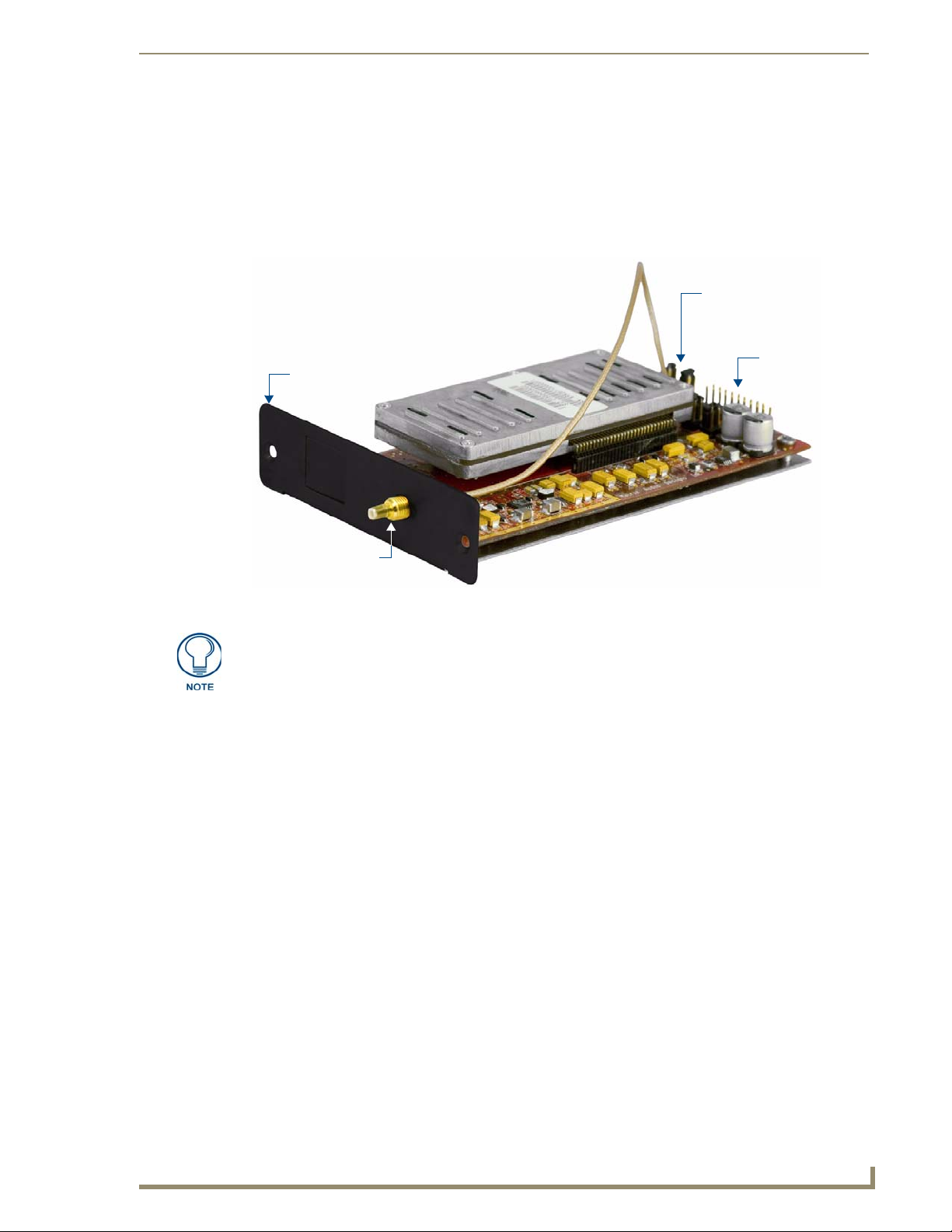
Add Sirius satellite radio functionality to your AMX Distributed Audio system with the DAS-SIRIUS Satellite
Radio Tuner Module (FG1110-02).
Tuner
Mounting
Plate
DAS-SIRIUS Tuner Module
Tuner Jumpers
20-pin Tuner
Ribbon Cable
connector
SIRIUS Antenna
connector
FIG. 1 DAS-SIRIUS Satellite Radio Tuner Module
“SIRIUS”, the SIRIUS dog logo, and channel names and logos are trademarks of
SIRIUS Satellite Radio Inc. All rights reserved.
The DAS-SIRIUS Tuner Module can be used with both Mi-Series and Tango Audio Controllers.
All Mi-Series and Tango Audio Controllers come equipped with a DAS-AMFM AM/FM Tuner
Module. Since Mi-Series and Tango Audio Controllers support 2 Tuner Modules in any
combination, the DAS-SIRIUS Module can either be installed in addition to the DAS-AMFM
Module, or the DAS-AMFM Module can be removed to allow 2 DAS-SIRIUS Modules.
Each Tuner Module uses 1 source input on the Audio Controller.
DAS-SIRIUS Sirius Satellite Radio Tuner Module
1
Page 6
DAS-SIRIUS Tuner Module
Installation
Installing/removing Tuner Modules requires removing the cover from the Audio Controller, removing the
Tuner Option cover plate from the rear panel of the Controller, installing the Tuner Module, and setting
Jumpers on both the Tuner Module to specify each Tuner as either TUNER 1 or TUNER 2, and on the rear
board pin-bus of the Audio Controller to enable/disable Tuner 1 and 2.
Disconnect all power sources before opening the chassis. Failure to disconnect
power before performing this installation may cause injury or death.
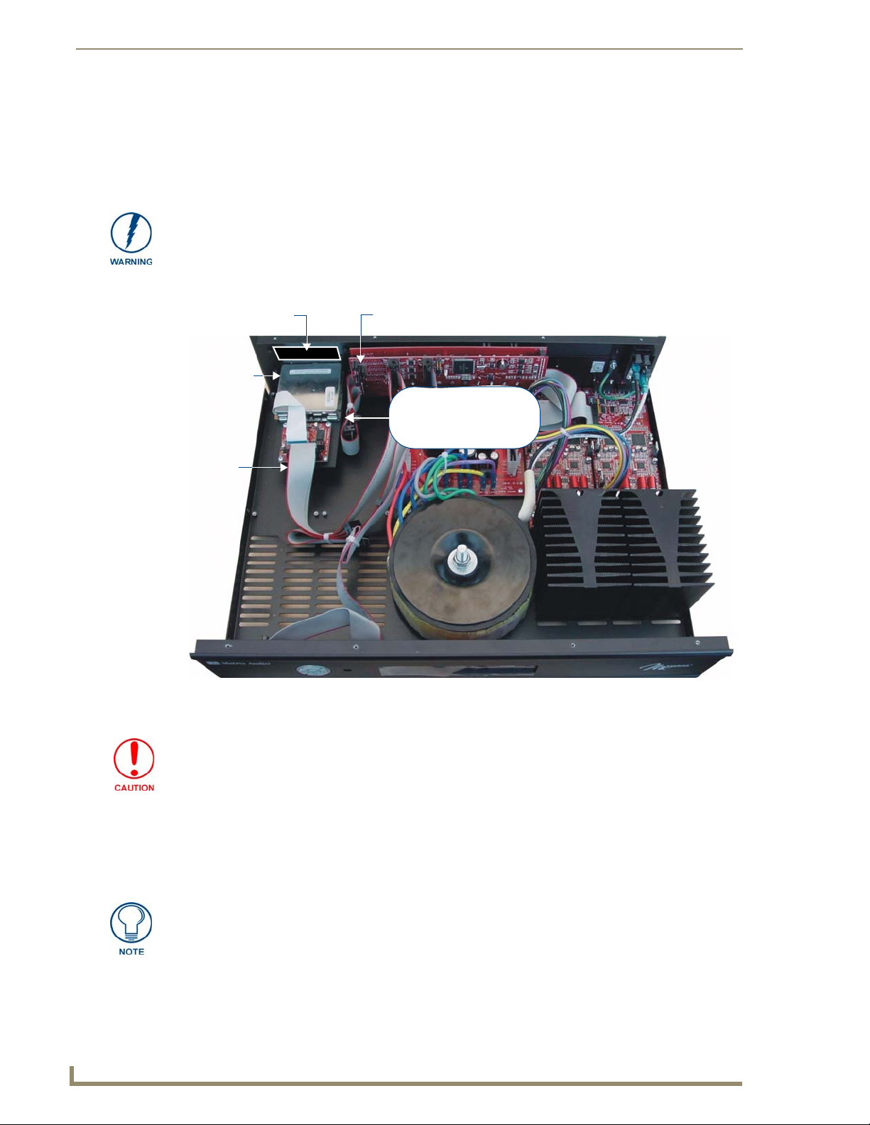
FIG. 2 provides orientation for the various internal components that must be accessed to install the Tuner and
set the Jumpers.
AMFM Tuner
installed in
(20-pin)
(with faceplate)
Module
Slot 2
Tuner
Ribbon
Cable
Slot 1
Rear-Board Pin Bus
(Controller Jumpers)
rear
Tuner slots:
Top = Slot 1
Bottom = Slot 2
front
FIG. 2 Audio Controller - Internal view
Discharge all static electricity from your body before touching any components of the
Tuner Modules or the Audio Controller. Failure to do so may lead to permanent
damage to the Tuner or Controller.
Setting the Jumpers
While Mi-Series and Tango Audio Controllers support 2 Tuner Modules in any combination, this document
describes installing the DAS-SIRIUS Tuner Module into Slot 1 (as TUNER 2), leaving the DAS-AMFM Tuner
Module in Slot 2 (as TUNER 1).
Because of the location of the Jumpers in the Controller and on the Tuner Module, it
may be easier to make all jumper settings before installing the Tuner Module in the
Controller.
2
DAS-SIRIUS Sirius Satellite Radio Tuner Module
Page 7
DAS-SIRIUS Tuner Module
Audio Controller Jumpers - Location
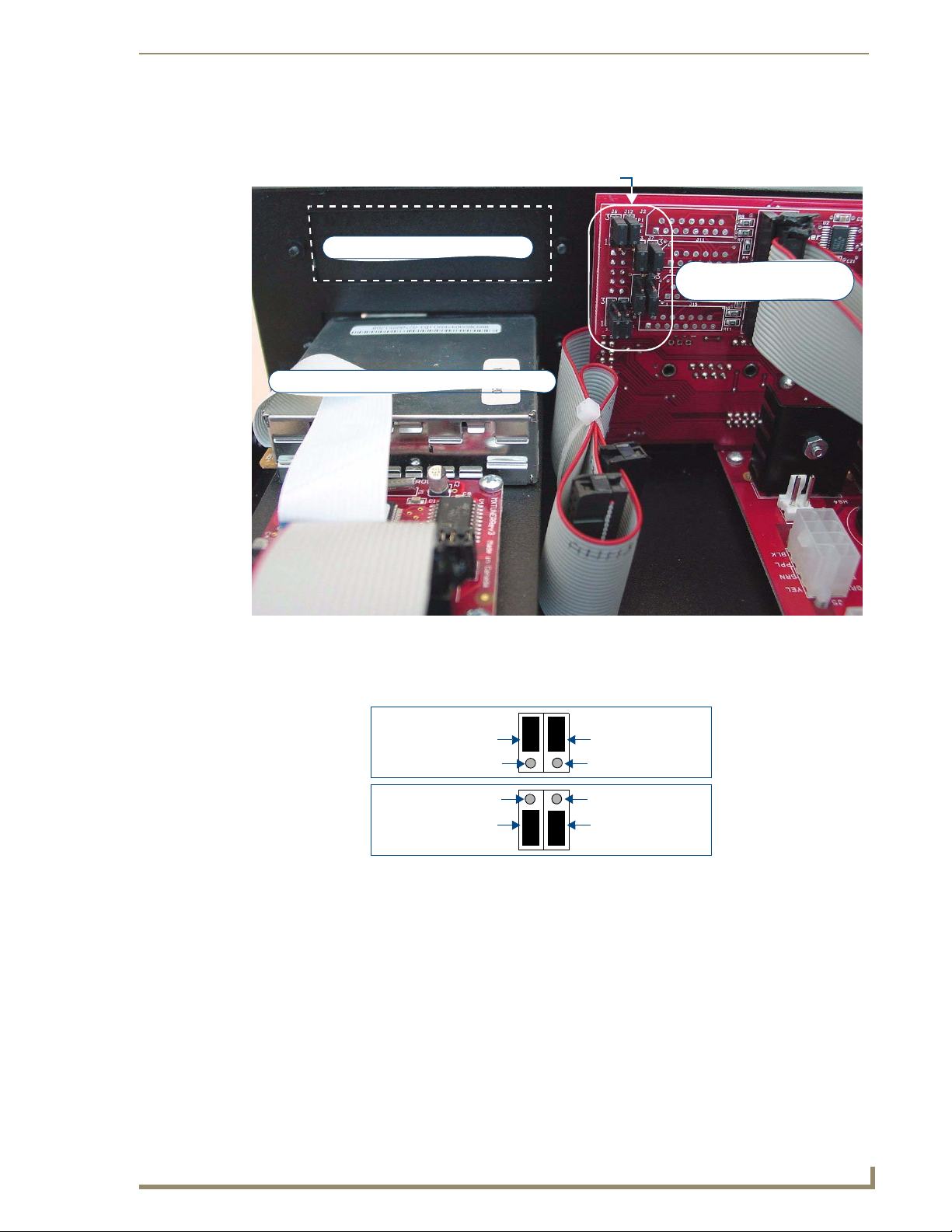
Examine the configuration of the jumpers on the left-side Rear-Board Pin Bus, as seen when viewing the rear
board from the front of the Controller (FIG. 3).
Audio Controller Jumpers
Slot 1 (with faceplate installed)
Rear-Board Pin Bus -
(see Fig 4 & 5)
Slot 2 (with AM/FM Tuner module installed)
rear panel
FIG. 3 Audio Controller - Rear-Board Pin Bus / Jumpers
Audio Controller Jumpers - ON/OFF Settings
ON position = pins 3 and 2 jumpered (with pin 1 exposed).
OFF position = pins 2 and 1 jumpered (with pin 3 exposed).
ON position
(Jumper pin 1 & 2)
OFF position
(Jumper pins 2 & 1)
FIG. 4 Controller Jumper Settings
Jumper (pins 3-2)
exposed pin (1)
exposed pin (3)
Jumper (pins 2-1)
3
1
3
1
Jumper (pins 3-2)
exposed pin (1)
exposed pin (3)
Jumper (pins 2-1)
DAS-SIRIUS Sirius Satellite Radio Tuner Module
3
Page 8
DAS-SIRIUS Tuner Module
Audio Controller Jumpers - Dual Tuner Setting
With the DAS-SIRIUS Tuner installed in Slot 1 (top), and the DAS-AMFM Tuner installed in Slot 2 (bottom),
the Audio Controller jumpers should all be set to ON, as shown in FIG. 5:
3
TUNER 1
Jumpers
TUNER 2
Jumpers
FIG. 5 Audio Controller Jumper Configuration (Dual Tuners)
1
3
1
3
Tuner 1 jumpers (in ON position)
1
3
Tuner 2 jumpers (in ON position)
1
Top Left of Rear-Board Pin Bus
Move the TUNER 2 jumpers to the ON position by connecting the top 2 sets of pins (pins 3-2) and leaving the
bottom pins (pin 1) exposed.
DAS-SIRIUS Tuner Module Jumper Settings (Standard Installation)
There are 2 sets of Jumpers on the DAS-SIRIUS Tuner Module (FIG. 6). These must be set to differentiate
Tuner 1from Tuner 2 in the Controller.
Since Mi-Series and Tango Audio Controllers are shipped with a DAS-AMFM Tuner Module pre-installed in
Slot 2 (as Tuner 1), the DAS-SIRIUS Tuner Module, is typically installed in Slot 1(as Tuner 2).
DAS-SIRIUS Tuner 1 & 2 Jumpers
20-pin Tuner
Ribbon Cable
Connector
FIG. 6 DAS-SIRIUS Tuner Module - Tuner 1 & 2 Jumper locations
4
DAS-SIRIUS Sirius Satellite Radio Tuner Module
Page 9

DAS-SIRIUS Tuner Module
Tuner 1 Jumper Settings
The DAS-SIRIUS Tuner Module defined as Tuner 1 must be set to Tuner 1 via jumpers on the Tuner, as shown
in FIG. 7:
TUNER 1 Jumpers
TUNER 1 Jumpers
FIG. 7 Tuner Module - Tuner 1 Jumper Configuration
Tuner 2 Jumper Settings
The DAS-SIRIUS Tuner Module defined as Tuner 2 must be set to Tuner 2 via jumpers on the Tuner, as shown
in FIG. 8:
TUNER 2 Jumpers
TUNER 2 Jumpers
FIG. 8 Tuner Module - Tuner 2 Jumper Configuration
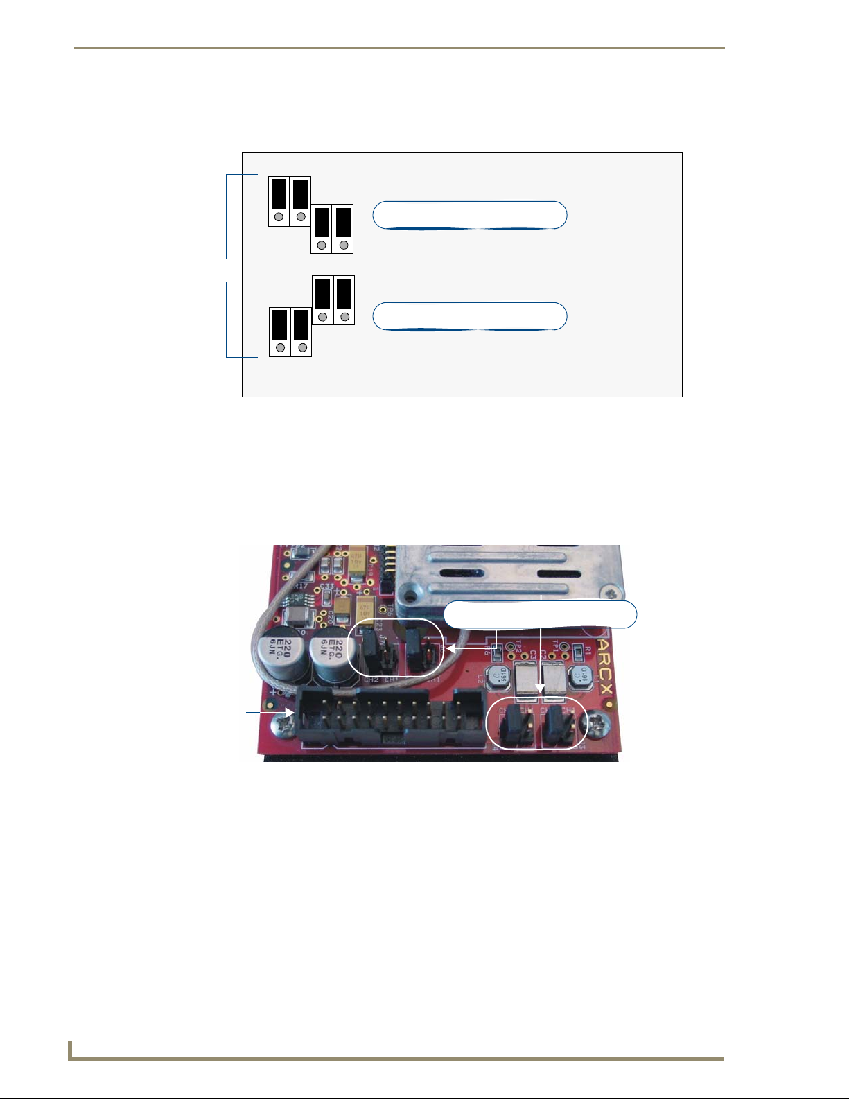
Changing the Jumper Settings on the DAS-AMFM Tuner Module
By default, a DAS-AMFM Tuner Module is installed in Slot 2. There are jumpers on the DAS-AMFM Tuner
Module that differentiate Tuner 1 from Tuner 2 in the Controller. By default, DAS-AMFM Tuner Modules are
set to the single tuner configuration.
When adding the DAS-SIRIUS Tuner Module to the Controller, it is necessary to change the jumper
settings on the pre-installed DAS-AMFM Tuner Module, to allow a second Tuner.
The jumpers on the DAS-AMFM Tuner Module (FIG. 9) must be set to differentiate Tuner 1from Tuner 2 in
the Controller.
Examine the configuration of the jumpers located on the Tuner Modules, to the right of the 20-pin ribbon cable
connector (as seen when viewing the installed modules from the front of the controller).
Note that there are two rows of 5 pins as shown in FIG. 9.
With only a single tuner, all pins are jumpered.
empty pins
(no jumpers)
FIG. 9 Tuner Module Jumper Configuration
Single Tuner
(all pins jumpered)
Dual Tuners:
TUNER 1
Dual Tuners:
TUNER 2
All DAS-AMFM AM/FM Tuner Modules are shipped in the single tuner configuration.
DAS-SIRIUS Sirius Satellite Radio Tuner Module
5
Page 10

DAS-SIRIUS Tuner Module
Installing the DAS-SIRIUS Tuner Module
The DAS-SIRIUS Tuner is typically installed into Slot 1 (see FIG. 2):
1. Remove the cover from the Audio Controller chassis.
2. Remove the cover plate (labelled “Tuner Option”) on the rear panel (FIG. 10) to expose Slot 1.
FIG. 10 Rear Panel - Tuner Slots 1 and 2
3. Carefully insert the DAS-SIRIUS Tuner Module into the Controller (electronics facing up), and replace
Be careful not to damage the white ribbon cable on the top of the Tuner Module.
Slot 1
(Tuner Option cover plate installed)
Slot 2
(DAS-AMFM installed)
the cover plate screws to secure the Module to the Controller.
The Rear Panel connector at the end of the Tuner Ribbon Cable is connected to the Controller’s rear
board pin-bus (see FIG. 2).
Keep the Tuner Ribbon Cable oriented so that the red stripe is always on top, in order to preserve
the orientation of the pins on the Tuner connectors. The red stripe on the ribbon cable indicates Pin
1 (FIG. 11):
not used
Slot 2 Slot 1
(see Note below)
FIG. 11 Tuner Ribbon Cable
RED STRIPE (to Pin 1)
Rear Panel
4. Connect the Slot 1 connector on the ribbon cable to the 20-pin Tuner Ribbon Cable connector on the
DAS-SIRIUS Module (FIG. 12).
Verify that all of the 20-pin connectors of the Tuner Ribbon Cable are securely plugged into their
respective boards.
6
DAS-SIRIUS Sirius Satellite Radio Tuner Module
Page 11

rear of Controller
(side view)
Slot 1 connector
(connect to DAS-SIRIUS
Module)
DAS-AMFM
DAS-SIRIUS Tuner Module
(shown connected to DAS-AMFM Module)
Slot 2 connector
FIG. 12 Tuner 1 / 2 Module Connections (side view of Controller)
Tuner Ribbon
Cable
While it is recommended that you use the Slot 2 connector on the ribbon cable to
connect the Tuner installed in Slot 2 (in this case, the DAS-AMFM Tuner), the ribbon
cable itself does not determine which Tuner is Tuner 1 and Tuner 2.
This determination is set by the jumper settings on each Tuner Module (see “Tuner 1
Jumper Settings” and “Tuner 2 Jumper Settings” above. Therefore, it is not required
that the connections indicated in FIG. 10 are followed exactly, as long as the Tuner
Jumper Settings are set correctly for each installed Tuner Module.
The Controller should only be powered back on once all Tuners are installed and the cover is replaced on the
chassis.
Removing Tuner Modules
In some cases it is necessary to remove the existing Tuner Module, in order to install a different Tuner. Since
each Tuner Module uses 1 source input on the Audio Controller, you may choose to use the source input for
other purposes.
1. Remove the cover from the Audio Controller.
2. Carefully remove the ribbon cable from the Tuner Module.
3. Remove the screws from the Tuner Module cover plate (on the Controller’s rear panel) and carefully slide
the Tuner Module out of the chassis.
4. To remove TUNER 1, place the TUNER 1 Audio Controller jumpers in the OFF position (FIG. 13).
Top Left of Rear-Board Pin Bus
3
TUNER 1
Jumpers
1
3
Tuner 1 jumpers (in OFF position)
FIG. 13 Audio Controller Jumper Configuration (No TUNER 1)
5. To remove TUNER 2, place the TUNER 2 Audio Controller jumpers in the OFF position (FIG. 14).
6. To remove both Tuner Modules, set all Audio Controller jumpers in the OFF position.
DAS-SIRIUS Sirius Satellite Radio Tuner Module
1
7
Page 12

DAS-SIRIUS Tuner Module
TUNER 2
Jumpers
FIG. 14 Audio Controller Jumper Configuration (No TUNER 1)
Connecting and Positioning the SIRIUS Antenna
1. Connect the provided SIRIUS Antenna to the DAS-SIRIUS (see FIG. 1).
2. Verify the Signal strength
Top Left of Rear-Board Pin Bus
3
3
1
Tuner 2 jumpers (in OFF position)
1
a. Via the programming menus via the front of the Controller, select Setup\SIRIUS.
b. Select Status. In this menu, you can check the following:
• ANT: Antenna Status
• ACT: Activation Status
• SAT: Satellite Signal
• TER: Terrestrial Signal
c. Select "SAT" to determine the Satellite Signal Strength (None, Wea k or Good).
d. Ensure the signal strength is at a minimum of "weak". Adjustments may need to be made to the
position of the Antenna in order to get a better signal.
Activating Your SIRIUS Subscription
SIRIUS Satellite Radio is a subscription service. In order to use your DAS-SIRIUS module, you will have to
activate your SIRIUS subscription.
Until you have activated your subscription, you will only be able to tune to channels
0 and 184.
1. Once you have installed the DAS-SIRIUS module, you can activate your SIRIUS subscription by phone:
Call 1.888.539.SIRIUS (7474).
2. You will be asked for a “Sirius ID”. This ID can be found in several places:
If using a Matrix LCD keypad, select channel "0" to display the Sirius ID.
If using either a Metreau or Matrix tactile keypad with the optional numeric keypad, select channel
"0". The Sirius ID will be displayed on the LCD display on the front of the Controller.
If using either a Metreau or Matrix tactile keypad without the optional numeric keypad, access the
programming menus via the front of the Controller by pressing the centre Nav button on the
Controller:
Select Setup\SIRIUS, then select ID from the SIRIUS menu, and the SIRIUS ID will be displayed.
8
DAS-SIRIUS Sirius Satellite Radio Tuner Module
Page 13

Mi Series – SIRIUS Setup screen
Accessing the SIRIUS Setup Screen
1. To access the SIRIUS menus on the Controller, press the SELECT button on the front of the Controller.
The following screen will be displayed (FIG. 15):
FIG. 15 Mi Series Controller - Main Menu
2. Select Setup to display the System Setup Mode screen. If an on-board DAS-SIRIUS module is detected,
SIRIUS is displayed on this screen.
3. Select SIRIUS (FIG. 16).
Mi Series – SIRIUS Setup screen
FIG. 16 System Setup Mode menu
Use the Navigation button array (<< / >>) on the front of the Controller to navigate
through the menus, and the “SELECT” button to make a selection.
If there are two SIRIUS modules on-board, there is an additional screen that allows you to choose
between the two (FIG. 17):
FIG. 17 SIRIUS Setup Mode menu (for Controllers with two DAS-SIRIUS modules on-board)
SIRIUS Setup
1. When SIRIUS is selected, the SIRIUS Setup screen is displayed (FIG. 18):
Exit SIRIUS Setup
Status
SIRIUS ID
Channel
Category
FIG. 18 SIRIUS Setup screen
The options on this page are described in the following sub-sections:
DAS-SIRIUS Sirius Satellite Radio Tuner Module
9
Page 14

Mi Series – SIRIUS Setup screen
SIRIUS Setup - CAT
Selecting CAT (Category) displays the following screen (FIG. 19), where the Category can be selected by
choosing PREV/NEXT. The default = 1 All.
FIG. 19 SIRIUS Category screen
Category will be updated to the LCD keypads after exiting the Controller setup
screens.
SIRIUS Setup - CH
Selecting CH (Channel) will display the following screen (FIG. 20), where a Channel can be selected by
choosing PREV/NEXT.
FIG. 20 SIRIUS Channel screen
Channel will be updated to the LCD keypads after exiting the Controller setup
screens
Presets can be set via this screen if the installer chooses. There are 10 available preset positions. Presets
can also be set at the keypad.
SIRIUS Setup - ID
Selecting ID displays the SIRIUS ID (FIG. 21).
FIG. 21 SIRIUS ID screen
SIRIUS Setup - Status
Selecting STATUS will display the following SIRIUS status screen (FIG. 22):
10
Exit SIRIUS Setup
Terrestrial Signal Level
Satellite Signal Level
Activation Status
Antenna Status
FIG. 22 SIRIUS Status screen
DAS-SIRIUS Sirius Satellite Radio Tuner Module
Page 15

Controlling SIRIUS via the LCD Keypad
Controlling SIRIUS via the LCD Keypad
Overview
The LCD keypad is a full touch screen keypad with two tactile buttons that are used for Volume
UP/DOWN. There are 3 LCD screens for the SIRIUS Source (FIG. 23):
• HOME screen User can select any of the available sources
• MAIN screen Displays metadata, including: Channel #, Channel Name, Artist, Song Title &
Composer and any SIRIUS messages.
The options on this screen allow the user to Channel UP/DOWN, recall presets,
and direct numeric control.
• MORE screen Displays metadata: Channel #, Channel Name, Artist, Song Title & Composer
and any SIRIUS messages.
The options on this screen provide access to the Channel List and Category List
screens, and allow the user to view and select Channels and Categories from a
list, set Presets and Favorites and access the NUMERIC screen for direct
numeric control
LCD Keypad - Home screen LCD Keypad - Main screen LCD Keypad - MORE screen
FIG. 23
DAS-SIRIUS Sirius Satellite Radio Tuner Module
LCD Keypad - SIRIUS screens
11
Page 16

Controlling SIRIUS via the LCD Keypad
Selecting SIRIUS as the Audio Source
On the Home screen, SIRIUS will appear in the top left touch field and is considered to be Source 1 (FIG. 24).
FIG. 24 LCD Keypad - Home screen
To turn ON the SIRIUS source, touch the text “SIRIUS”. The screen will change to the SIRIUS
Main Screen and the
Volume UP to the desired volume level.
SIRIUS SAT Main screen
There are two lines of metadata display on the LCD Keypad with a maximum display of 14 characters per line
(FIG. 25).
Select SIRIUS (Source 1)
> icon appears in front of the text to indicate that SIRIUS is ON in that room.
Display Line #1 - Channel #, Name
Display Line #2 - Artist, Song Title,
Composer
Channel NextChannel Prev
Display the Preset screen
where the user can select 1
of 10 available presets
Displays the
Home screen
FIG. 25 LCD Keypad - SIRIUS SAT Main screen
Display the Numeric screen where the
user can enter the channel number
directly
Displays the SIRIUS
MORE screen
Display Line #1 Channel # & Channel Name
Channel # + Channel Name will be displayed up to a max. of 14 characters.
This display line scrolls once and stops.
Touch the line of text to update the text and scroll the info once.
Display Line #2 Artist Name, Song Title & Composer
The Artist, Song Title & Composer are displayed up to a max. of 14 characters.
This display line scrolls once and stops.
Touch the line of text to update the text and scroll the info once.
Channel - / Channel +
Touch Channel – to select the previous channel/station and begin playing.
Touch Channel+ to select the next channel/station and begin playing.
12
DAS-SIRIUS Sirius Satellite Radio Tuner Module
Page 17

Controlling SIRIUS via the LCD Keypad
SIRIUS Preset screen
Touch Preset on the SIRIUS SAT Main screen (FIG. 25 on page 12) to display the Preset screen where the user
can select 1 of 10 available presets (FIG. 26).
Select Presets 1-10
Return to the SIRIUS
SAT Main screen
FIG. 26 LCD Keypad - SIRIUS Preset screen
SIRIUS NUMERIC screen
Touching NUMERIC on the SIRIUS SAT Main screen (FIG. 25 on page 12) displays the standard Numeric
screen where the user can directly key in the Channel of their choice (FIG. 27).
Numeric buttons
Use the "point" button
to specify channels
that use a point in their
channel number
(Ex: 90.1)
FIG. 27 LCD Keypad - SIRIUS NUMERIC screen
Selects the channel
Press the numeric buttons to specify a channel number, and press Enter to select. When the Channel is
selected:
SIRIUS Satellite Radio does not utilize points for it’s channels. Therefore, the "point"
button is used for other Source types (such as AM/FM tuner, CD, etc.), but not for
SIRIUS channels.
The SIRIUS MAIN screen is displayed, and the Channel selected begins playing.
The Channel #, Channel Name, Artist, Song Title & Composer are displayed.
DAS-SIRIUS Sirius Satellite Radio Tuner Module
13
Page 18

Controlling SIRIUS via the LCD Keypad
SIRIUS MORE>> screen
Touch MORE on the SIRIUS SAT Main screen (FIG. 25 on page 12) to display the SIRIUS MORE screen
(FIG. 28).
List Channels List Categories
Set Presets
Return to the SIRIUS
SAT Main screen
FIG. 28 LCD Keypad - SIRIUS MORE screen
Set Favorites
The options on this screen allow the user to perform the following:
List Channels
List Categories
Set Presets
Set Favorites
List - Channels
Touch CH LIST on the SIRIUS MORE screen (FIG. 28 on page 14) to display the List-Channel screen, with
the current channel displayed (FIG. 29).
Scroll down
Return to the
SIRIUS MORE screen
FIG. 29 LCD Keypad - SIRIUS List Channels screen
To scroll through the channels, touch “SCROLL +” or “SCROLL –”. When scrolling, up to 3 channels will be
displayed
Touch any channel to select it. When the Channel is selected:
The SIRIUS MAIN screen is displayed & the Channel selected begins playing.
The Channel #, Channel Name, Artist, Song Tit le and Composer are displayed.
Scroll up
14
DAS-SIRIUS Sirius Satellite Radio Tuner Module
Page 19

Controlling SIRIUS via the LCD Keypad
List - Category
Touch CAT on the SIRIUS MORE screen (FIG. 28 on page 14) to display the List-Category screen, with the
current category displayed (FIG. 30).
Scroll down
Return to the
SIRIUS MORE screen
FIG. 30 LCD Keypad - SIRIUS List Categories screen
Scroll up
To scroll through the Categories, touch SCROLL + or SCROLL –. When scrolling, up to three Categories
will be displayed.
To select a category, touch the category of choice. When the Category is selected:
The SIRIUS MAIN screen is displayed, and the default Channel (set by the SIRIUS module) within
the Category selected begins playing.
The Channel #, Channel Name, Artist, Song Title and Composer are displayed.
SIRIUS - Presets
Users can set up to 10 presets per source.
1. From the SIRIUS More screen (FIG. 28 on page 14), touch PRESET, to access the Numeric screen
(FIG. 31).
Key in a channel that you
want to set a Preset for,
using the Numeric buttons
Use the "point" button
to specify channels
that use a point in their
channel number
(Ex: 90.1)
FIG. 31 LCD Keypad - SIRIUS Presets screen
2. Use the numeric buttons to key in the Channel.
3. Touch ENTER.
4. A Preset screen is displayed. Select the Preset # you wish to assign to the selected channel.
5. To set another preset, repeat steps 2 – 3.
DAS-SIRIUS Sirius Satellite Radio Tuner Module
Selects the channel
15
Page 20

Controlling SIRIUS via the LCD Keypad
SIRIUS - Favorites
Favorites is a standard functionality of the Matrix Controller and is available for all sources.
One minute after an “ALL OFF” has been performed, or 10 Minutes after every zone/room has been turned off,
the controller will send a Power OFF command to all sources.
The first time a source is turned on in any room (after a system power off), if a favorite has been set for that
room and that source, the favorite station/channel will begin playing.
For example: A “favorite” channel of “7” is set in Room 1 for the SIRIUS source type. If Room 1 is the first
room to be turned ON after a system OFF, Channel 7 will begin playing (whether it was the last channel played
or not.
1. From the SIRIUS More screen (FIG. 28 on page 14), touch SET FAV, to access the Favorites screen
(FIG. 32).
SIRIUS MORE screen
FIG. 32 LCD Keypad - SIRIUS Favorites screen
Return to the
2. From the SIRIUS Favorites screen (FIG. 19), select SET FAV. A numeric screen will be displayed. Key in
the channel to be set as the favorite, and select ENTER.
16
DAS-SIRIUS Sirius Satellite Radio Tuner Module
Page 21

SIRIUS – Tactile Keypad
FIG. 33 shows the navigation button layout for Tactile Keypads.
SIRIUS – Tactile Keypad
Nav Up
Nav Left
FIG. 33 Tactile Keypad
Nav Right
Nav Down
SIRIUS Source Control
When the Source type = SIRIUS, the navigation buttons perform the following functions:
• NAV UP NEXT Channel/Station (Ch 9, 10, 11 etc.)
• NAV DOWN PREV Channel/Station (Ch 9, 8, 7 etc.)
• NAV RIGHT NEXT PRESET (Preset 1, 2, 3…)
• NAV LEFT PREV PRESET (Preset 1, 10, 9, 8…)
• NAV CENTRE NOT USED
• NAV CENTRE Hold NOT USED
DAS-SIRIUS Sirius Satellite Radio Tuner Module
17
Page 22

SIRIUS – Tactile Keypad
18
DAS-SIRIUS Sirius Satellite Radio Tuner Module
Page 23

SIRIUS Messages
Overview
Messages specific to the DAS-SIRIUS tuner module that can be displayed on the Controller or LCD Keypad
include:
• Loss of Signal: “Acquiring Signal”
• Antenna Error: “Antenna Error”
• Subscription Updates: “Subscription Updated”
• Channel Map Updates: “Updating Channels”
• Invalid Channel: “Invalid Channel”
• Unsubscribed Channel: “CALL 888-539-SIRIUS TO SUBSCRIBE”
When first powering ON the Controller, and the user selects the SIRIUS source, the Initializing
SIRIUS message is displayed, until the signal is detected.
Channel in Tuning is displayed until the channel is tuned, then the standard SIRIUS metadata is
displayed.
When initially powering ON the Controller, the display of metadata on the LCD
Keypad may be slower until it is buffered by the SIRIUS module. Since the Controller
is always ON, therefore, the SIRIUS module is always on, so this delay is only
noticeable when first installing the Matrix Distributed Audio system.
SIRIUS Messages
SIRIUS ID Display
The SIRIUS ID can be displayed from two places:
Controller > Setup/SIRIUS/ID
LCD Keypad by keying in channel 0 from the numeric screen (or by tuning to channel 0 using the
CH + / - buttons).
Invalid Channels
Invalid Channels will be automatically skipped when navigating channels via CH+/-.
DAS-SIRIUS Sirius Satellite Radio Tuner Module
19
Page 24

It’s Your World - Take Control™
3000 RESEARCH DRIVE, RICHARDSON, TX 75082 USA • 800.222.0193 • 469.624.8000 • 469-624-7153 fax • 800.932.6993 technical support • www.amx.com
2009 AMX. All rights reserved. AMX and the AMX logo are registered trademarks of AMX. AMX reserves the right to alter specifications without notice at any time.
©
10/09
 Loading...