

AMX DAS-M-0806, DAS-M-0606, DAS-M-0608, DAS-M-0804, DAS-M-0808 Operation/reference Manual
...Page 1

Operation/Reference Guide
Mi Series
Distributed Audio Controllers
DAS-M(I)0404/6/8 4 Source, 4/6/8 Zone Controller
DAS-M(I)0604/6/8 6 Source, 4/6/8 Zone Controller
DAS-M(I)0804/6/8 8 Source, 4/6/8 Zone Controller
Distributed Audio
Last Revised: 6/02/2008
Page 2

AMX Limited Warranty and Disclaimer
This Limited Warranty and Disclaimer extends only to products purchased directly from AMX or an AMX Authorized Partner which
include AMX Dealers, Distributors, VIP’s or other AMX authorized entity.
AMX warrants its products to be free of defects in material and workmanship under normal use for three (3) years from the date of
purchase, with the following exceptions:
• Electroluminescent and LCD Control Panels are warranted for three (3) years, except for the display and touch overlay components are warranted for a period of one (1) year.
• Disk drive mechanisms, pan/tilt heads, power supplies, and MX Series products are warranted for a period of one (1) year.
• AMX lighting products are guaranteed to switch on and off any load that is properly connected to our lighting products, as long
as the AMX lighting products are under warranty. AMX also guarantees the control of dimmable loads that are properly connected to our lighting products. The dimming performance or quality there of is not guaranteed, impart due to the random combinations of dimmers, lamps and ballasts or transformers.
• AMX software is warranted for a period of ninety (90) days.
• Batteries and incandescent lamps are not covered under the warranty.
• AMX AutoPatch Epica, Modula, Modula Series4, Modula CatPro Series and 8Y-3000 product models will be free of defects in
materials and manufacture at the time of sale and will remain in good working order for a period of three (3) years following the
date of the original sales invoice from AMX. The three-year warranty period will be extended to the life of the product (Limited
Lifetime Warranty) if the warranty card is filled out by the dealer and/or end user and returned to AMX so that AMX receives it
within thirty (30) days of the installation of equipment but no later than six (6) months from original AMX sales invoice date. The
life of the product extends until five (5) years after AMX ceases manufacturing the product model. The Limited Lifetime Warranty
applies to products in their original installation only. If a product is moved to a different installation, the Limited Lifetime Warranty
will no longer apply, and the product warranty will instead be the three (3) year Limited Warranty.
All products returned to AMX require a Return Material Authorization (RMA) number. The RMA number is obtained from the AMX
RMA Department. The RMA number must be clearly marked on the outside of each box. The RMA is valid for a 30-day period. After
the 30-day period the RMA will be cancelled. Any shipments received not consistent with the RMA, or after the RMA is cancelled, will
be refused. AMX is not responsible for products returned without a valid RMA number.
AMX is not liable for any damages caused by its products or for the failure of its products to perform. This includes any lost profits, lost
savings, incidental damages, or consequential damages. AMX is not liable for any claim made by a third party or by an AMX Authorized Partner for a third party.
This Limited Warranty does not apply to (a) any AMX product that has been modified, altered or repaired by an unauthorized agent or
improperly transported, stored, installed, used, or maintained; (b) damage caused by acts of nature, including flood, erosion, or earthquake; (c) damage caused by a sustained low or high voltage situation or by a low or high voltage disturbance, including brownouts,
sags, spikes, or power outages; or (d) damage caused by war, vandalism, theft, depletion, or obsolescence.
This limitation of liability applies whether damages are sought, or a claim is made, under this warranty or as a tort claim (including
negligence and strict product liability), a contract claim, or any other claim. This limitation of liability cannot be waived or amended by
any person. This limitation of liability will be effective even if AMX or an authorized representative of AMX has been advised of the
possibility of any such damages. This limitation of liability, however, will not apply to claims for personal injury.
Some states do not allow a limitation of how long an implied warranty last. Some states do not allow the limitation or exclusion of incidental or consequential damages for consumer products. In such states, the limitation or exclusion of the Limited Warranty may not
apply. This Limited Warranty gives the owner specific legal rights. The owner may also have other rights that vary from state to state.
The owner is advised to consult applicable state laws for full determination of rights.
EXCEPT AS EXPRESSLY SET FORTH IN THIS WARRANTY, AMX MAKES NO OTHER WARRANTIES, EXPRESSED OR
IMPLIED, INCLUDING ANY IMPLIED WARRANTIES OF MERCHANTABILITY OR FITNESS FOR A PARTICULAR PURPOSE. AMX
EXPRESSLY DISCLAIMS ALL WARRANTIES NOT STATED IN THIS LIMITED WARRANTY. ANY IMPLIED WARRANTIES THAT
MAY BE IMPOSED BY LAW ARE LIMITED TO THE TERMS OF THIS LIMITED WARRANTY. EXCEPT AS OTHERWISE LIMITED
BY APPLICABLE LAW, AMX RESERVES THE RIGHT TO MODIFY OR DISCONTINUE DESIGNS, SPECIFICATIONS, WARRANTIES, PRICES, AND POLICIES WITHOUT NOTICE.
Page 3

IMPORTANT SAFETY INSTRUCTIONS
IMPORTANT SAFETY INSTRUCTIONS
1. Read instructions.
2. Keep these instructions.
3. Heed all warnings.
4. Follow all instructions.
5. Do not use this apparatus near water.
6. Clean only with dry cloth.
7. Do not block any ventilation openings. Install in accordance with the manufacturer’s
instructions.
8. Do not install near any heat sources such as radiators, heat registers, stoves, or other
apparatus (including amplifiers) that produce heat.
9. Do not defeat the safety purpose of the grounding-type plug. The grounding plug has two
blades and a third grounding prong. The third prong is provided for your safety. If the provided
plug does not fit into your outlet, consult an electrician for replacement of the obsolete outlet.
10. Protect the power cord from being walked on or pinched particularly at plugs, convenience
receptacles, and the point where they exit from the apparatus.
11. Only use attachments/accessories specified by the manufacturer.
12. Use only with cart, stand, tripod, bracket, or table specified by the manufacturer, or sold with the
apparatus. When a cart is used, use caution when moving the cart/apparatus combination to
avoid injury from tip-over.
13. Unplug this apparatus during lightning storms or when unused for long periods of time.
14. Refer all servicing to qualified personnel. Servicing is required when the apparatus has been
damaged in any way, such as power supply cord or plug is damaged, liquid has been spilled or
objects have fallen into the apparatus, the apparatus has been exposed to rain or moisture,
does not operate normally, or has been dropped.
Warning: Shock Hazard - The lightning flash within an equilateral triangle, intended to
alert the user to the presence of un-insulated “Dangerous voltage” within the products
enclosure that may be of significant magnitude to constitute a risk of electric shock to
persons
Read Accompanying Documentation – The exclamation point within an equilateral
triangle is intended to alert the user to the presence of important operating and
maintenance (servicing) instructions in the literature accompanying the product.
15. The fuse should only be replaced with a T8AL250V fuse.
16. The RCA, RJ11and RJ45 Jacks shall only be used for their intended use. Refer to
accompanying documentation to insure that they are being used as intended.
17. The spring clip terminals and F-connector on the tuner module should only be used to connect
an AM and FM antenna.
18. A grounded power outlet is required for safe operation.
19. The grounded 3 prong power cable will be the mains disconnect and it should remain readily
available.
20. To completely disconnect the unit from the AC mains, disconnect the power supply cord plug
from the AC receptacle.
21. The main voltage for the AC mains is 120v AC (US Models) / 240v AC (Int’l models).
Warning – To reduce the risk of fire or electric shock, do not expose this apparatus to rain or
moisture. Do not expose this equipment to dripping or splashing and ensure that no objects filled
with liquids are placed on the equipment.
Mi Series Audio Controllers
a
Page 4

IMPORTANT SAFETY INSTRUCTIONS
b
Mi Series Audio Controllers
Page 5

Table of Contents
Table of Contents
IMPORTANT SAFETY INSTRUCTIONS ................................................................ a
Mi Series Audio Controllers ................................................................................1
Overview .................................................................................................................. 1
Product Specifications..................................................................................................... 2
Mi Series Features........................................................................................................... 3
Source Components.................................................................................................. 3
IR Emitters....................................................................................................................... 4
Keypad Controls ............................................................................................................. 4
DAS-IRRX-SWT Stealth IR Receiver ................................................................................. 5
IR Remote Controls................................................................................................... 6
DAS-MRC Mi Series IR Remote Control........................................................................... 6
Mi Series Audio Zone Expanders .................................................................................... 7
Tuner Antenna Installation........................................................................................ 7
Speaker Wire Technology (SWT)............................................................................... 7
Wiring and Connections .....................................................................................9
Pre-Installation Precautions and Recommendations ................................................. 9
Note to Professional Installers ........................................................................................ 9
Installing Source Equipment............................................................................................ 9
Cabling Installation Instructions................................................................................ 9
Cable Type .................................................................................................................... 10
RF Interference.............................................................................................................. 10
Distribution Wiring........................................................................................................ 10
Considerations for New Construction Installations ................................................. 10
Securing the Cables ...................................................................................................... 10
Keypad “Rough In” Locations ....................................................................................... 10
Considerations for Existing Construction................................................................ 11
Running Wires in Existing Construction......................................................................... 11
Marking the Cables ....................................................................................................... 11
Existing Electrical Boxes for Keypads ........................................................................... 11
Considerations for Outdoor Zones ......................................................................... 11
Outdoor Wiring............................................................................................................. 11
Outdoor Keypads.......................................................................................................... 12
Controller Connections ........................................................................................... 12
Audio Component and Emitter Lead Connections ........................................................ 12
RS-232 Cable .......................................................................................................... 13
Matrix MRC RS-232 Command Definition ..................................................................... 13
General ......................................................................................................................... 13
Mi Series Audio Controllers
i
Page 6

Table of Contents
Using Four Conductor Speaker Wire ............................................................................ 14
Using a Zone Expander ................................................................................................ 14
Special Wiring Configurations................................................................................. 15
Auxiliary Amplifier Configuration .................................................................................. 15
Remote Amplifier Configuration ................................................................................... 16
2 Wire Configurations – Keypad for Control Only......................................................... 16
Split Zone / Analog Volume Control (Option 1) One Keypad........................................ 17
Split Zone / Analog Volume Control (Option 2) Two Keypads ...................................... 18
Multiple Keypads in Zone.............................................................................................. 18
Connecting Matrix Keypads.................................................................................... 19
Wire Color Schemes ...................................................................................................... 19
Zone Connections.......................................................................................................... 19
Installation into the Wall Cavity..................................................................................... 19
Connecting Matrix In-Ceiling Speakers ................................................................... 20
Overview - Speaker Wire Technology (SWT) ................................................................. 20
Overview - Matrix Speakers .......................................................................................... 20
Wiring Method A........................................................................................................... 21
Method B (Retrofit) ....................................................................................................... 22
Source Power Handling ................................................................................................. 22
Quick Functionality Test ................................................................................................ 22
Programming ....................................................................................................23
Overview ................................................................................................................ 23
Source Documentation .................................................................................................. 23
Key-By-Key Programming ............................................................................................. 23
Programming Worksheets ............................................................................................. 23
Programming the Mi Series Controller ................................................................... 24
The Programming Panel ................................................................................................ 24
Main Menu screen................................................................................................... 24
System Setup Mode screen .................................................................................... 25
System Setup - MRC Setup Mode screen ...................................................................... 25
MRC Setup Mode Options screen ................................................................................. 26
Programming Source Equipment ............................................................................ 26
Learn IR Commands....................................................................................................... 30
Setting Gain/Attenuation .............................................................................................. 31
Adjusting Input Attenuation.......................................................................................... 31
Adjusting Output Gain .................................................................................................. 32
Paging ........................................................................................................................... 33
Setting Paging Volume.................................................................................................. 33
Room Control Settings .................................................................................................. 33
System Setup - Tuner Setup Mode screen .............................................................. 34
ii
Mi Series Audio Controllers
Page 7

Table of Contents
Selecting AM/FM .......................................................................................................... 34
Selecting Stereo/Mono ................................................................................................. 34
Seeking ......................................................................................................................... 34
Setting Presets .............................................................................................................. 35
System Setup - Clock Setup Mode screen .............................................................. 35
Setting System Time ..................................................................................................... 35
Setting System Date ..................................................................................................... 36
Setting the Day of the week ......................................................................................... 36
Viewing Alarms ............................................................................................................. 36
Backlight Options screen ........................................................................................ 37
Backlight - Intensity....................................................................................................... 37
Backlight - Mode ........................................................................................................... 37
About Options screen............................................................................................. 38
Device Status ................................................................................................................ 38
Program LCD KP ........................................................................................................... 39
Basic Keypad Functions ....................................................................................41
Source Selection ..................................................................................................... 41
Navigation Command Keys..................................................................................... 41
Muting the System.................................................................................................. 41
All On/Off ............................................................................................................... 41
Bass, Treble, Balance and SRS ................................................................................ 41
Bass Mode..................................................................................................................... 41
Treble Mode.................................................................................................................. 42
SRS Mode...................................................................................................................... 42
Privacy Mode .......................................................................................................... 42
Volume Control....................................................................................................... 42
Source Keypads (DAS-KP-4e-G, DAS-KP-6e-G) ....................................................... 43
Volume Control ............................................................................................................ 43
Navigation Button Functions ........................................................................................ 43
Tone Control Mode (Bass, Treble, Balance & SRS).................................................. 44
BASS control mode ...................................................................................................... 44
TREBLE control mode.................................................................................................... 45
SRS control mode (WOW, BASS BOOST, 3D & FOCUS) ............................................... 45
Privacy Feature.............................................................................................................. 46
Zone Control - On/Off................................................................................................... 46
SOURCES & how they work .......................................................................................... 46
Advanced Keypad Controls ..............................................................................47
Overview ................................................................................................................ 47
Direct Access Controls............................................................................................ 47
Mi Series Audio Controllers
iii
Page 8

Table of Contents
Direct Numeric Access - CD Player/Changer ................................................................. 47
Direct Numeric Access - Satellite Radio/Video .............................................................. 47
Direct Numeric Access – Digital Cable Music ................................................................ 47
Direct Tuning .......................................................................................................... 48
Matrix On-Board TUNER – (STATION) + (ENTER).......................................................... 48
Setting and Recalling Presets ................................................................................. 48
Setting “Presets” per Source, via Numeric Keypad (1-0) .............................................. 48
To Create a Preset......................................................................................................... 49
To Recall a Preset .......................................................................................................... 49
To Clear All Presets ....................................................................................................... 49
Zone Grouping (Buttons 1 & 2)............................................................................... 50
Group Mode.................................................................................................................. 50
To Add a Zone To a Group............................................................................................ 50
Group All Zones ............................................................................................................ 50
Un-group All Zones ....................................................................................................... 51
Group Volume Control .................................................................................................. 51
Favorites (Buttons 3 & 4) ........................................................................................ 51
Setting Favorites ........................................................................................................... 51
Creating a Favorite for a Specific Source ...................................................................... 52
Clear Favorite for a Specific Source and Specific Zone ................................................. 52
Clear All Favorites for All Sources in a Specific Zone .................................................... 52
Alarm Settings (Buttons 5 & 6) ............................................................................... 53
Alarm Clock - Overview ................................................................................................. 53
Setting System/Clock Time............................................................................................ 53
Set Alarm Time (from each Keypad) .............................................................................. 54
Clear Alarm For a Specific Zone/Room.......................................................................... 54
Clear Alarm for All Zones/Rooms .................................................................................. 54
Keypad Lockout (Buttons 7 & 8) ............................................................................. 55
Setting Keypad Lockout (Buttons 7& 8) ........................................................................ 55
Lock a Specific Keypad.................................................................................................. 55
Unlock a Specific Keypad .............................................................................................. 56
Unlock All Keypads........................................................................................................ 56
Using DAS-KP LCD-G/W Keypads ....................................................................57
Overview ................................................................................................................ 57
Labeling the Keypad Grids ..................................................................................... 57
Customizing LCD Keypad Labels ............................................................................ 58
Customizing Source Labels ..................................................................................... 58
Customizing Source Command Labels .................................................................... 59
Basic Functionality ................................................................................................. 60
iv
Mi Series Audio Controllers
Page 9

Table of Contents
Turn On a Source (single room) ..................................................................................... 60
Turn Off a Source (single room) .................................................................................... 60
Turn a Source On in All Rooms...................................................................................... 60
Turn All Rooms Off (System Off) ................................................................................... 60
KP-LCD Advanced Functionality Screen.................................................................. 61
Paging/Privacy Mode.............................................................................................. 61
Direct Entry (From The Source Main Screen) .......................................................... 62
Tuner............................................................................................................................. 62
CD ................................................................................................................................. 62
Cable / Satellite............................................................................................................. 62
Presets (Setting & Recalling) .................................................................................. 63
Setting a Preset............................................................................................................. 63
Recalling a Preset .......................................................................................................... 63
Advanced Functionality (Mi & Delta Series) ............................................................ 63
Tone Control (Bass/Treble/Balance/SRS) ...................................................................... 63
Backlight Options ......................................................................................................... 64
Advanced Functionality (Mi Series only) ................................................................. 64
Grouping Rooms .......................................................................................................... 64
Setting/Clearing the Alarm Clock ................................................................................. 65
Locking/Unlocking Keypads ......................................................................................... 66
RS-232 Commands / Messages ......................................................................... 67
RS-232 Controller Command Messages ................................................................. 67
Tango Audio Controller Status Messages .............................................................. 73
Source Command Codes......................................................................................... 79
Sirius Status Codes ................................................................................................. 80
AMX Duet Module Interface Specifications ......................................................81
Port Mapping.......................................................................................................... 81
Channels ................................................................................................................. 81
Levels...................................................................................................................... 83
Command Control .................................................................................................. 83
Command Feedback ............................................................................................... 86
Input Source Types ................................................................................................ 88
Troubleshooting ...............................................................................................89
Overview ................................................................................................................ 89
Power Connections ................................................................................................. 89
Source Unit Connections......................................................................................... 90
Zone Connection Problems..................................................................................... 90
Dead Zones ................................................................................................................... 90
Mi Series Audio Controllers
v
Page 10

Table of Contents
LED Does Not light ....................................................................................................... 90
Source Connections....................................................................................................... 91
No Keypad Activity (At All)..................................................................................... 91
Keypad Lights, No Sound ....................................................................................... 92
Programming .......................................................................................................... 92
vi
Mi Series Audio Controllers
Page 11

Mi Series Audio Controllers
Overview
The Mi Series Audio Controller allows centralized control of common audio equipment for up to 8
independently controlled music zones per Controller. Each Mi Series Controller is capable of controlling
the source via keypad, RS-232, IP address (Ethernet Module), SWT Speakers (equipped with IR
receivers), or the DAS-IRRX-SWT Stealth IR receiver used with the (optional) DAS-MRC IR remote
control. Each zone is a music environment unto itself and can be configured independently for
characteristics such as volume, bass, treble, balance left, balance right and SRS
SRS/WOW is a registered trademark of SRS labs, Inc.
The Mi Series Controllers (FIG. 1) consist of a centralized amplifier and control system, controlled
locally by a Keypad. Each zone may also be configured with 2 control keypads. Each zone can be
configured with either 2 pushbutton keypads (Numeric or Source), or 1 LCD Keypad and 1 pushbutton
Keypad, but not 2 LCD keypads.
Other sources such as Satellite Receivers, CD Players, MP3 Players, and any other IR Controlled audio
source can be patched into the RCA source inputs located on the back panel.
Mi Series Controllers are available in 120V (DAS-M0404, -M0406, -M0408, -M0604, -M0606, -
M0608, -M0804, -M0806, -M0808), or 240V versions (DAS-MI0404, -MI0406, -MI0408, -MI0604, MI0606, -MI0608, -MI0804, -MI0806, -MI0808).
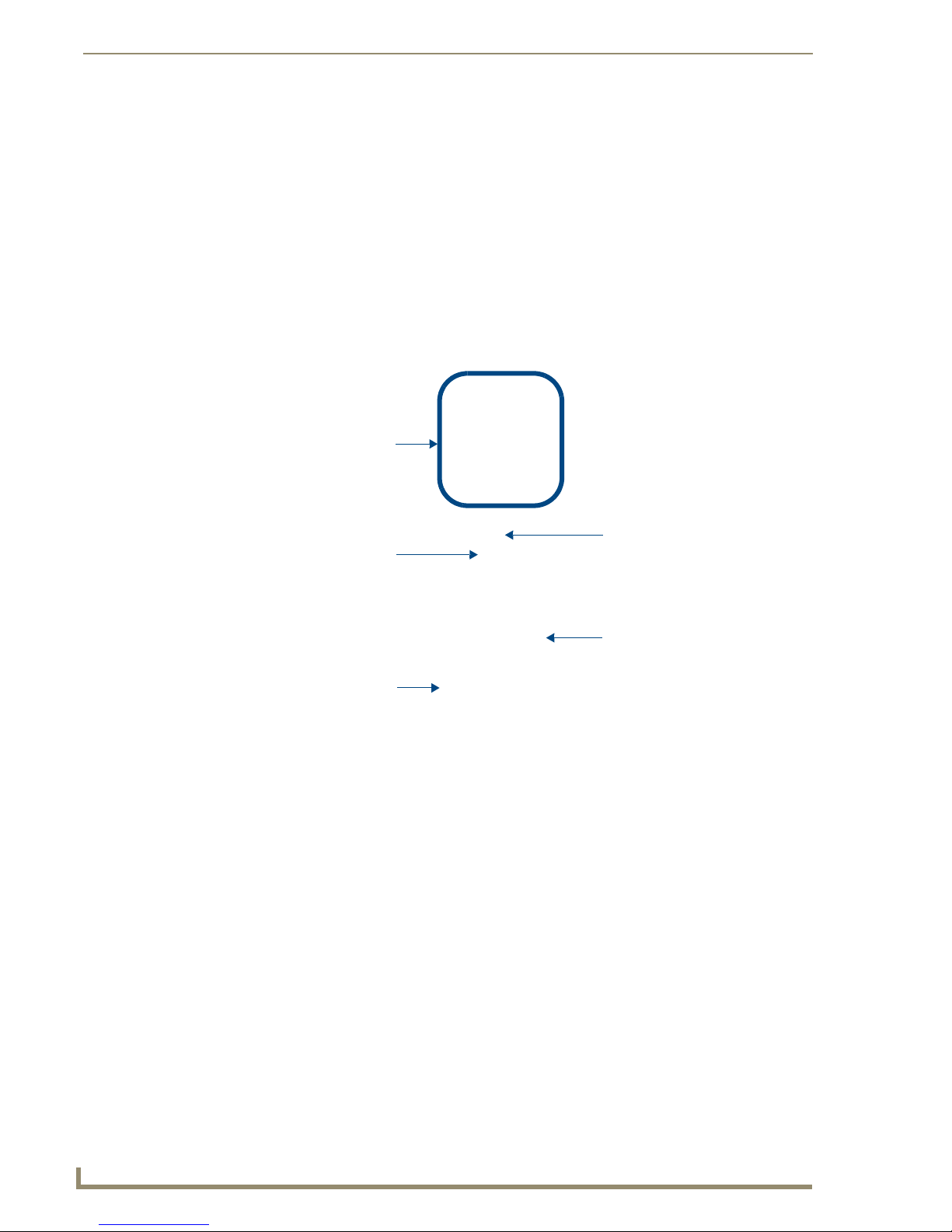
FIG. 1 illustrates the front and rear panel component layout for the Mi Series Controllers:
Mi Series Audio Controllers
®
.
Navigation Array Buttons
IR Receiver LCD Display Screen
Power Switch & Receptacle
FIG. 1 Mi Series 4 and 6 Audio Controllers
RS-232
Expansion Port (RJ45)
Paging IN/OUT ports
IR Outputs (6)
Zone Outputs (up to 8)
AM/FM
Antenna Inputs
Mi Series Audio Controllers
1
Page 12

Mi Series Audio Controllers
Product Specifications
The following table provides technical specifications for the Mi Series Controllers. Unless otherwise
noted, these specifications apply to Mi Series 4, 6 and 8 Controllers.
Mi Series Product Specifications
Models Available:
Mi Series 4 Audio Controllers
• DAS-M(I)0404(B/S) 4 Source, 4 Zone Controller (black or silver, 120V or 240V)
• DAS-M(I)0406(B/S) 4 Source, 6 Zone Controller (black or silver, 120V or 240V)
• DAS-M(I)0408(B/S) 4 Source, 8 Zone Controller (black or silver, 120V or 240V)
Mi Series 6 Audio Controllers
• DAS-M(I)0604(B/S) 6 Source, 4 Zone Controller (black or silver, 120V or 240V)
• DAS-M(I)0606(B/S) 6 Source, 6 Zone Controller (black or silver, 120V or 240V)
• DAS-M(I)0608(B/S) 6 Source, 8 Zone Controller (black or silver, 120V or 240V)
Mi Series 8 Audio Controllers
• DAS-M(I)0804(B/S) 8 Source, 4 Zone Controller (black or silver, 120V or 240V)
• DAS-M(I)0806(B/S) 8 Source, 6 Zone Controller (black or silver, 120V or 240V)
• DAS-M(I)0808(B/S) 8 Source, 8 Zone Controller (black or silver, 120V or 240V)
Stereo Output:
Power:
Zone Support:
Stereo Amplifiers:
SRS/WOW®:
Front Panel Components:
• Navigation Buttons Allow for front panel programming, selection of sources, and tuning AM/FM
• IR Receiver This is where you must aim the remotes from your audio source components
• LCD Display Displays information necessary during the programming steps and afterward
Rear Panel Components:
• Power Switch & Receptacle The master power switch will remain in the ON position
• Paging In/Out Ports RCA jacks to connect to Paging devices (any audio input can be used as a
• RJ 45 Port Ethernet Port for future expansion
• RS-232 Port 9-pin D connector to interface with NetLinx control systems.
• AM/FM Antenna Inputs Connections for the AM and FM Antennas.
• Audio Inputs Stereo Inputs, 47K impedance, buffered.
• Audio Outputs Stereo Looping Outputs, buffered.
• IR Outputs • Mi Series 4 - Four IR 3.5mm mono output jacks.
25 Watts/CH stereo (20Hz to 20Khz @ .1% THD)
960W max (Actual average usage = 300W)
• Eight independent Zones (4 X 2 Zone Modules).
• Each Zone is protected thermally.
• Zone grouping.
• Independent Volume, Bass, Treble, Balance and SRS
• 40 Watts/CH stereo amplifiers (20Hz to 20Khz @ .1% THD).
• Amplifiers are protected from overload and thermal runaway.
Standard SRS/WOW® audio enhancement technology by SRS Labs, on all zones.
Note: SRS/WOW is a registered trademark of SRS labs, Inc.
®
controls in each zone.
radio stations (when Controller is fitted with the optional tuner board). The
same array appears on the Matrix KP-4e navigational keypad.
so the Controller can learn and emulate those commands.
is the display to indicate information about the source input and zone activity.
normally.
paging device). The Paging device connects to the Controller via the "Paging
In" connector. The “Paging Out” connector is used to carry the page to Zone
Expander(s).
• Mi Series 6 - Six IR 3.5mm mono output jacks.
• Mi Series 8 - Eight IR 3.5mm mono output jacks.
2
Mi Series Audio Controllers
Page 13

Mi Series Audio Controllers
Mi Series Product Specifications (Cont.)
• Zone Outputs Connections for up to 8 zone outputs that connect to the keypads.
• Expansion Port RJ 11 Port connects main Controller with Zone Expanders.
Available Colors: Black, Silver
Dimensions (HWD):
(including feet)
Weight: Max. weight with 8 zones - 31 lbs (14.06 kg)
• 4" x 17" x 13.5"
• 10.16 cm x 43.18 cm x 34.29 cm
Mi Series Features
Mi Series Controllers are expandable up to (64) zones. When the system is expanded beyond
8 zones an Audio Zone Expander is used to achieve the desired number of zones. Audio Zone
Expanders can supply up to (8) zones each in 4 or 8 zone increments.
Balancing the system could never be easier. Mi Series Controllers have Input Attenuation
and Output Gain Settings. Each source can be leveled to approximately the same level
insuring a smooth transition between source selections.
Mi Series Controllers allow the user to setup each Keypad to take them to their favorite radio
station, satellite channel or CD when a source is selected. The “Favorite Mode” makes the
whole listening experience seamless.
Turning the system on could never be easier. Not only does the series allow you to set up any
of the rooms into “Groups”. The group mode will allow you to set up the volume and the
source for the zones in the group.
“Keypad Lockout” allows the user to lockout the Keypad in any room from any Keypad. This
stops other users from using the system from the keypads that are locked.
The “Privacy Mode” locks out the paging override. This allows a specific zone to remain
silent as required
The Alarm clock allows the system to be turned on and off at scheduled times.
Mi Series Controllers are programmed from the front panel.
Speaker Wire Technology (SWT) utilizes standard speaker cable to provide not only music
to each zone but uses the same cable to interface with the controlling Keypad. This technology
presents attractive installation options, which may allow you to utilize existing cable
distribution in retrofit applications and allows for faster quicker installations.
Source Components
The Mi Series 4 supports up to (4) stereo audio source inputs.
The Mi Series 6 supports up to (6) stereo audio source inputs.
The Mi Series 8 supports up to (8) stereo audio source inputs.
Audio components are connected to the Mi Series Controllers on the back panel. Each audio input has a
corresponding buffered output used to connect the audio sources to additional Controllers or to other
devices that share the audio sources. This device supports RC5 and RC6 IR codes. Codes that fall outside
of this range may not function with the Controller. Industry standard RCA connectors at the rear of the
unit provide line-level input and output connections for devices such as CD, DSS, MP3 players etc. Two
Tuners can be installed onboard the Mi Series Controller.
Be aware that the tuners, when installed, will take up the first and second source inputs respectively.
Each source component is selected using the appropriate button on the Keypad, remote or other interface
which corresponds to one of the Mi Series 4, 6, or 8 audio device inputs (labeled as: input 1, input 2, and
input 3 respectively).
Mi Series Audio Controllers
3
Page 14

Mi Series Audio Controllers
The Mi Series Controller is capable of learning IR commands from the audio components remote
control, allowing you to assign commands such as Channel Up or Down to keys on the system keypads.
Just as a radio is incapable of playing two different stations at the same time, if
multiple zones are listening to the same source, they will be listening to the same
music. You may wish to consider multiple components of the same type (such as the
tuner) if different zones wish to listen to different radio stations at the same time.
IR Emitters
In addition to the RCA line input / output connections for each of the audio devices, there are also
connections for IR emitters (supplied) which completes the control circuit between the Controller and
the individual audio devices attached to the system (FIG. 2). Any commands received from the remote
keypads are processed and sent down the control lead to the audio device. Commonly available IR
emitter leads are unobtrusive, and attach to the audio device’s remote control sensor with double sided
tape, and connect to the Controller by 3.5mm mono output jacks located at the back of the unit.
FIG. 2 IR Emitter
Keypad Controls
The Mi Series Controller is accessed by remote keypads that provide basic transport control, source
selection and volume up and down.
Also available is the DAS-KP-NUM-G, a direct access Numeric Keypad that provides enhanced control
over the connected audio source devices. Some of these controls include direct access capability,
favorite’s source selection, zone grouping, setting the alarm clock, and Keypad lockout (FIG. 3).
DAS-KP-4e-G DAS-KP-NUM-G DAS-KP-LCD-GDAS-KP-6e-G
FIG. 3 Matrix Keypads
Matrix Keypads are compatible with both Delta and Mi Series Audio Controller Systems. Refer to the
Audio Controller Keypads Operation/Reference Guide for details on installing and using the Keypads.
4
Mi Series Audio Controllers
Page 15

Mi Series Audio Controllers
DAS-IRRX-SWT Stealth IR Receiver
In addition to the Keypad selection, the system can be designed to include the DAS-IRRX-SWT Stealth
IR Receiver (FIG. 4), which provides zone or room control in conjunction with or in lieu of the DASKP-4e-G, DAS-KP-6e-G or DAS-KP-LCD Keypad. The DAS-IRRX-SWT is a solution based product
which allows the user to overcome either architectural or environmental constraints.
FIG. 4 DAS-IRRX-SWT Stealth IR Receiver
This IR Receiver consists of a small interface box which contains all of the control circuitry and a small
cylinder which houses the receiver. The interface box is typically installed in a wall or ceiling and is
connected to the receiver box by a 4 conductor wire.
The Receiver wire is attached by a 4-pin male plug which plugs into the 4-pin female jack on the
interface box. The location of the receiver should be positioned so that it has an unobstructed view with
the remote control.
The DAS-IRRX-SWT interface connects to the Controller in exactly the same manner as the KP series
Keypad. The Mi Series Controller can accommodate up to 2 devices per zone.
Each zone can be configured with either 1 or 2 pushbutton keypads, or 1 pushbutton
Keypad and 1 Stealth IR Receiver, or 1 LCD Keypad and 1 Stealth IR Receiver.
The DAS-IRRX-SWT offers the same level of control that a KP series Keypad provides including direct
access features. The DAS-MRC IR remote transmits all commands in exactly the same manner as the KP
Series keypads.
The DAS-MRC’s IR commands can be programmed into a learning remote.
Mi Series Audio Controllers
5
Page 16
Mi Series Audio Controllers
IR Remote Controls
The IR remote controls that are supplied by the manufacturer of the audio source equipment are used for
programming the Controller. However, the IR receiver on the DAS-KP-4e-G, DAS-KP-6e-G, DAS-KPLCD, and the DAS-IRRX-SWT user interfaces will not pass through IR commands issued by the audio
source remotes. It is intended to receive the remote IR signals generated by DAS-MRC remotes or by
learning-remotes that have stored the DAS-MRC remote codes.
DAS-MRC Mi Series IR Remote Control
The DAS-MRC Mi Series IR Remote Control (FG1101-50, 51) operates all the functions of the Mi
Series Keypads and can be used in any location where a Keypad, SWT Active speaker or Stealth IR
Receiver has been installed (FIG. 5).
Source Selection Buttons
Blue LED
Numeric Entry Buttons
Navigation Array Buttons
Volume UP/DOWN Buttons
FIG. 5 DAS-MRC IR Remote Control
Each Keypad has an integrated IR receiver to detect and process IR commands as if the Keypad had been
accessed directly.
6
Mi Series Audio Controllers
Page 17

Mi Series Audio Controllers
Mi Series Audio Zone Expanders
Mi Series Audio Zone Expanders (FIG. 6) are used to expand the number of zones in the system beyond
the 8 that are available using the Mi Series Controller. Each Audio Zone Expander has the capability of
offering (4 or 8) zones per Audio Zone Expander. Up to seven Expanders may be used in the system,
offering the ability to expand the system to 64 zones.
FIG. 6 Mi Series Audio Zone Expander (DAS-M0808X shown)
For detailed instructions on the installation and use of the Mi Series Audio Zone Expanders, please refer
to the Mi Series Audio Zone Expander Installation Guide, available at www.amx.com.
Tuner Antenna Installation
The TA-MOD tuner requires a 75ohm F-type connection to receive FM stations. Connect a
75ohm antenna source into the 75ohm antenna input located on the back of the Controller.
The TA-MOD tuner requires an AM antenna loop to receive AM stations. Connect the loop
antenna source into the AM antenna input located on the back of the Controller.
Speaker Wire Technology (SWT)
Speaker Wire Technology (SWT) allows both data and audio signals to travel over the same four
conductor wire. This remarkable technology removes the need for control wire since the control and
audio signals are shared on the same wire. The reliability and simplicity of this system has been proven
for years. AMX Matrix Audio is the only company that offers a “retrofit solution”, one which allows the
replacement of volume controls with AMX Matrix Audio keypads and Controllers, giving full control
over the sources. Additionally, the versatility of SWT also allows AMX Matrix Audio products to be
connected where the control wire has been run separately from the speaker cable.
Mi Series Audio Controllers
7
Page 18

Mi Series Audio Controllers
8
Mi Series Audio Controllers
Page 19

Wiring and Connections
Pre-Installation Precautions and Recommendations
The Mi Series system is extremely flexible. It can be installed in a number of configurations depending
on your audio needs. The capacity of a single unit is 8 independent zones and is typically wired with at
least one keypad or DAS-IRRX-SWT Stealth IR Receiver located in each zone. In some cases it is
desirable to operate a second set of speakers within the same zone controlled by the same keypad. The
Mi Controller will power 2 sets of speakers as long as the impedance does not drop below 4 ohms.
If you have two common zones such as the Master Bedroom and Master Bathroom you can use a single
keypad and multiple analog volume controls for independent control of the two areas while sharing the
same source control capability. Up to 2 Matrix keypads can also be connected in a zone with a single pair
of speakers.
A system installation will go much faster and more smoothly if job plans are completed prior to the
actual installation. Accurate record keeping will assist not only in the installation but also in training the
client in the operation of the system. This will also be a great tool for any future servicing issues that
may arise.
We recommend that you make copies of the records, and leave them behind with your client, and put one
copy in your client’s file. For your convenience, Programming worksheets are available at
www.amx.com.
Wiring and Connections
Each zone can be configured with either 2 pushbutton keypads (Numeric or Source),
or 1 LCD Keypad and 1 pushbutton Keypad, but not 2 LCD keypads.
See the Multiple Keypads in Zone section on page 18 for details.
Note to Professional Installers
AMX always recommends professional installation for our products. As with any entertainment product
in a home or commercial application, a Matrix Distributed Audio system installation will go much faster
and more smoothly if job plans are completed prior to the actual installation.
Installing Source Equipment
To meet airflow and cooling requirements, place each audio source on an individual shelf and allow a
minimum of 3” clearance on the sides and top of the unit. Stacking equipment is not recommended as
this presents situations in which airflow is restricted or component cooling may be impaired. The audio
source equipment and the Controller will generate small amounts of heat that must be dissipated to
extend component life and maintain performance.
Equipment should have adequate room in the rear for the cables to reside. If rear access, or a rack a
mounted structure has been provided then cable installation will be much easier.
Cabling Installation Instructions
Please be sure to check for any wiring restrictions required by the electrical code in your area.
This installation uses low voltage cabling similar to telephone and alarm wiring, and as such does not
commonly have very many restrictions on their installation. However rules may vary in different regions.
Please check with your local code enforcement official to determine if any specific conditions must be
met to comply with local electrical codes.
Mi Series Audio Controllers
9
Page 20

Wiring and Connections
Cable Type
The Mi Series Controller is cabled using standard 4-conductor speaker cable originating at the MRC
passing through the Keypad and terminating at the speaker location. AMX generally recommends using
a bundled 4 conductor 16 gauge stranded copper wire in a single continuous run.
RF Interference
Shielded cable is generally not required for audio installations. Although the Mi Series Controller does
generate radio emissions, it uses a digital signaling path during command entry. These emissions have
been accommodated for in design and conform to RF emission standards. There are normally no
ongoing data communications in the circuit path. Communications only occur at the time a command is
issued from a zone. However many other systems do use microprocessor systems where the cabling may
be in close proximity such as telephone and security systems, and it is possible for different systems to
interfere with each other. If you face an installation where your cable runs are in parallel to these types of
systems you may consider shielded cable to the keypads. In this case ground the drain wire by
connecting it to the chassis of the Mi Series Controller.
Distribution Wiring
In general, wiring is installed in a single continuous run between the Controller, the Keypad and the
speaker location. Other cable routing options such as a home run to a common wiring distribution point,
integration with home automation systems, or split zone applications can be significantly different than
the general information presented here. These applications are left to the installer’s discretion and
experience. Examples of common wiring options can be found in the Special Wiring Configurations
section of this document.
Considerations for New Construction Installations
It’s generally accepted to run the 2 and 4 conductor speaker cables inside walls, in the attic and between
the joists in the basement or crawl space. When installing cables within walls, drill the holes in the
middle of the studs to avoid having them damaged by screws or nails that could penetrate the cable. Use
metal nail guard plates where necessary to protect the cable from future construction damage or from
something like nails/screws that are installed to hang future pictures or shelving. When running cables in
the attic or crawl space, run them in such a way that they will be out of harm, where they will not be
stepped on, snagged, punctured, or could pose a safety hazard.
Do not run cable thru the return air path that utilizes the wall or ceiling space as the plenum.
Securing the Cables
We recommend using electrical cable straps to keep the installation neat and secure. We do not
recommend stapling the cables as a single misplaced staple can cause a short that causes trouble during
operations and set-up. Do not leave the wires lying in the dirt under the crawl space. Neatness counts in
a professional installation.
Keypad “Rough In” Locations
The keypad device itself will fit in a standard electrical box or new construction plate and you should
install 1 or 2 gang (as required) standard electrical boxes to accommodate them before the drywall has
been put into place. Keep in mind that because these are low voltage applications, plastic electrical boxes
are generally adequate for the keypad, but check local building code requirements to be sure. The high
voltage electricians on the job site will know which electrical box is appropriate and within code.These
emissions have been accommodated for in design and conform to RF emission standards.
10
Mi Series Audio Controllers
Page 21

Wiring and Connections
Considerations for Existing Construction
For existing construction, successful implementation can be achieved by using retrofit electrical boxes
that do not require stud mounting or metal electrical frames which are commonly used for telephone and
cable installations. These “afterthought” low voltage electrical boxes can be placed in a standard opening
in the wall. Care must be taken when using these frames that they must not come in contact with the back
of the unit, or provide a shorting path at the cable connections.
When installing near other switches, make sure the boxes are dead level and lined up with existing
electrical boxes.
Running Wires in Existing Construction
A neat and careful installation in an existing construction application will increase the customer
satisfaction level as well as reduce the chance of service calls in the future. Run cables inside the walls
(wherever possible) to the attic, basement, or crawl space. Some installers cut the long straight section
from a coat hanger and chuck it into a drill to help establish a reference marker through ceilings and
floors up against the edge of a wall. The coat hanger wire is tough enough to drill through most materials
without snagging the carpet fibers. The wire is fairly unobtrusive and the length makes it easy to spot on
the other side. The small hole left behind is usually hidden by the carpet, or easily repaired. Holes in the
stud wall for the wiring can then be made by taking into account the width of the baseboard, drywall, and
half the stud (usually 1/2” + 1/2” + 1- 1/ 2 or 2- 1/ 2” from the pilot hole.)
If you must run wires in a room that is carpeted, you can carefully place the cables under the baseboard
or you can lift the edge of the carpet and place the wiring between the carpet’s tack strip and the wall. Be
careful going past doorways or across a walking path. A cable doesn’t seem too big until it’s tripped over
or causes an unsightly lump in the carpet, so please consider cable diameter where necessary. In some
cases when running wire under carpet or a threshold, you may discover that multiple 2 conductor speaker
wiring will sit flatter than a single bundled 4 conductor wire.
Marking the Cables
When running each cable, carry a fine tip permanent marker with you and mark both ends of the cable.
When you get to the keypad location, mark a couple of arrows on the cable to show you in which
direction the speakers are and in which direction the Controller is. This will save you time, eliminating
the need to “Ohm-out” the cables later to find the one you’re looking for. A few additional seconds spent
during the wiring stage will save you hours of cable chasing later.
Existing Electrical Boxes for Keypads
Due to the varying manufactured sizes of electrical plates and boxes carefully mark a level and plumb
outline of the switch box using the box itself as a template and make a hole in the existing wall with a
drywall or reciprocating saw. Please be careful to ensure that the space you’re cutting into does not hide
any plumbing, electrical or heating fixtures that could be damaged or cause personal injury. Care must
also be taken when dealing with outside walls. The vapor barrier should be repaired if damaged.
Considerations for Outdoor Zones
Outdoor listening zone locations present some unique challenges, both for the wiring and for the control
keypad placement.
Outdoor Wiring
Special care should be taken when cables transit outside the home. It is not recommended that keypads
be installed in environments subject to extreme temperatures, or moisture. Typically keypads are
installed inside the home and beside the door adjacent to the outside music zone. Keypads that must be
installed outside are done at your own risk and should be installed in weatherproof electrical boxes. The
DAS-IRRX-SWT Stealth IR Receiver provides an excellent solution for outdoor use. Keypads used
Mi Series Audio Controllers
11
Page 22

Wiring and Connections
outdoors should be safely mounted inside a weatherproof electrical box with a door covering the Keypad
and adequate water barrier seals to protect the unit.
External cabling should run through conduit (plastic electrical conduit works well) to protect it from the
elements and small animals that may wish to chew on the cable. You may wish to consider a qualified
electrical contractor to install cable conduit for external applications. Cable and installation accessories
to complete your installation are not part of the system package, and can be obtained at your local
electrical supply retailer.
Outdoor Keypads
Choosing the location of the keypad control device is perhaps the most important decision. It is not
recommended that keypads be installed in environments subject to extreme temperatures, or moisture.
Typically keypads are installed inside the home and beside the door adjacent to the outside music zone,
but this may not always be possible or practical.
Keypads that must be installed outside are installed at your own risk and should be installed in
weatherproof electrical boxes.
Keypads used outdoors should be safely mounted inside a weatherproof electrical box with a door
covering the keypad and adequate water barrier seals to protect the unit. Once again, the appropriate
weather proof enclosures can be obtained at your local electrical supply house, national home
improvement centres, and even at most neighborhood hardware stores. Be sure to check what is available
and plan your installation before doing the work with an outdoor zone because the materials you have (or
do not) have available could easily influence the choices you make to execute the installation.
Keypads installed outside must be inside a weatherproof box with a cover that seals
out moisture. Keypads returned to AMX for repair that are found to be corroded will
not be covered under the AMX Warranty.
Controller Connections
Audio Component and Emitter Lead Connections
Plug the RCA audio cables from each source device into the RCA jacks provided on the back of the
Controller. Ensure that right and left are connected correctly. The balance setup will not image properly
if reversed. Then connect the IR emitter leads for each audio source into the appropriate connector on the
back of the Controller, and run the optical end of the emitter lead to the source device’s IR receiver
window (FIG. 1).
FIG. 1 Audio Component and IR Emitter Lead Connections
12
Mi Series Audio Controllers
Page 23

Wiring and Connections
RS-232 Cable
When connecting to the RS-232 port located on the back of the Mi Series Controller, it is necessary to
use a DB9 cable. The Mi Series Controller utilizes DCE protocol therefore no NULL modem adapter is
necessary. You may also use a USB to DB9 adapter.
Matrix MRC RS-232 Command Definition
Connector: DB9 Male
Communications: 9600 Baud, 8 data bits, 1 stop bit, no parity
General
All messages are sent using ASCII text strings. Every command and status message is terminated with a
line feed (0x0A or 10). All messages are case sensitive.
The MRC will respond to the command messages sent by the Host and will not send any messages
except in this case. If the Host sends a new message before the MRC has responded to the previous
message, the MRC will ignore the new message.
The Host should always start its communication with the MRC by sending a “Get Configuration”
command to determine the capabilities of the unit it is controlling.
Not all MRC products support all of the functionality which is specified in the Command Definition.
Commands must be in UPPERCASE • Valid Commands do not require CR/LF
Valid Commands are confirmed with “Command Issued”
Invalid commands are responded to with “ERROR”
A complete listing of the RS-232 commands for the Mi Series Controller is available
for download via the InConcert section of the www.amx.com website (search
"Manufacturers" for "AMX Matrix").
Mi Series Audio Controllers
13
Page 24

Wiring and Connections
Using Four Conductor Speaker Wire
IR OUT LINE IN
Mi Series
Controller
Shared 4-conductor keypad/speaker wire
FIG. 2 System Integration Drawing Using Four Conductor Speaker Wire
Using a Zone Expander
IR OUT LINE IN
Zones 1-8
Mi Series
Controller
LINE IN RJ11
Mi Series Audio Zone Expander
FIG. 3 System Integration Drawing Using a Zone Expander
Shared 4-conductor keypad/speaker wire
14
Mi Series Audio Controllers
Page 25

Wiring and Connections
Special Wiring Configurations
Auxiliary Amplifier Configuration
In some cases you may require more power for a given zone than the Mi Series Controller, or Carbon XA
can provide. You may purchase a DAS-LLC to provide a line level output to incorporate a larger external
amplifier, or you can make your own line level converter.
FIG. 4 shows the construction of a simple circuit of discrete components to reduce the "speaker level"
output of the Mi Series Controller to “line level" so that it can drive an auxiliary amplifier.
Mi Series Controller
Zone Output Terminal Connector
DATA
Ground (-)
Left Speaker
R1, R3 = 47K 1/4 Watt Resistor
R2, R4 = 10K 1/4 Watt Resistor
R1
Left RCA Jack to Amp Right RCA Jack to AMP
R2
Left Speaker (+)
Left Speaker (-)
Right Speaker (+)
Right Speaker (+)
FIG. 4 Auxiliary Amplifier Configuration
R3
R4
KP Series Keypad
Terminator
Right Speaker
This amplifier would typically be installed at the equipment rack (head end).
Mi Series Audio Controllers
15
Page 26

Wiring and Connections
Remote Amplifier Configuration
In some cases, especially where the distance between the Mi Series Controller and the zone is unusually
long, such as another building on the property i.e. cottage-to-boathouse for example, it is sometimes
desirable to have a remote amplifier at the zone end.
You may install a DAS-LLC to accomplish this task or you may build your own. FIG. 5 shows the
construction of a simple circuit of discrete components to reduce the Mi Series Controller output to
“line- level” so that it can be fed into an auxiliary amplifier.
R1
Mi Series Controller
Zone Output Terminal Connector
R1, R3 = 47K 1/4 Watt Resistor
R3
R2, R4 = 10K 1/4 Watt Resistor
Left RCA Jack to Amp Right RCA Jack to AMP
FIG. 5 Remote Amplifier Configuration
R2
R4
2 Wire Configurations – Keypad for Control Only
In some retrofit configurations it is not feasible or possible to re-route the speaker cable through the
Keypad. In cases such as this, it is possible to run a separate cable pair (CAT- 3 / CAT- 5 / Twisted Pair)
cable from the Mi Series Controller to the Keypad device for control purposes. FIG. 6 shows the
connections of the control signal path to the Keypad, and the speaker connections to the Mi Series
Controller.
LD G R
Zone Output Connector
(on Mi Series Controller)
Cat5/Cat3/Twisted Pair
KP Series Keypad
Speaker Cable
Left Right
FIG. 6 2 Wire Configurations - Keypad for Control Only
16
+-- +
Mi Series Audio Controllers
Page 27

Wiring and Connections
Split Zone / Analog Volume Control (Option 1) One Keypad
In cases of split zones where more than one set of speakers are driven from the same Keypad (such as a
Reading nook off of the master bedroom) it is sometimes desirable to place a volume control in the split
zone.
FIG. 7 shows the connections to a remote zone, and “Autoformer” volume control device. Inure that
impedance setting don’t fall below 4 Ohms.
Zone Output Connector
(on Mi Series Controller)
Volume Control
LDGR
Right
KP Series Keypad
Left
FIG. 7 Split Zone / Analog Volume control (Option 2) one Keypad
It is not recommended to install more than 2 pair of speakers per zone.
If you are installing 2 pairs of speakers in a zone and the speakers are 8Ohms It is not
necessary to use an impedance matching autoformer type volume control. A standard stereo
volume control will perform properly. The impedance will be approximately 4 Ohms.
If you are using an impedance matching volume control with 2 pairs of speakers set the
impedance matching to the 2X setting.
Right
Left
Mi Series Audio Controllers
17
Page 28

Wiring and Connections
Split Zone / Analog Volume Control (Option 2) Two Keypads
In this case, two keypads are shown (FIG. 8). Please note this does not truly split the zone, but provides
controls in two areas of the same zone. If one Keypad selects a different source or changes the volume,
the change in source and volume will in both of the common zone changes.
Zone Output Connector
(on Mi Series Controller)
LDGR
Left
KP Series
SECONDARY
FIG. 8 Split Zone / Analog Volume control (Option 3) Two Keypads
KP Series
PRIMARY
Vol ume Co ntr ol
Right
Left
Right
Multiple Keypads in Zone
Certain situations such as large rooms or rooms with more than one common entrance may require more
than one keypad control to conveniently manage the zone. This configuration allows for 2 Keypads to be
placed on the control circuit (FIG. 9).
LDGR
Zone Output Connector
(on Mi Series Controller)
Left
KP Series
SECONDARY
FIG. 9 Multiple Keypads in Zone
18
KP Series
PRIMARY
Right
Vol ume Co ntr ol
Mi Series Audio Controllers
Left
Right
Page 29

Wiring and Connections
Connecting Matrix Keypads
Wire Color Schemes
It’s not particularly important to denote any one color as any one particular conductor. What is, however,
of critical importance is consistency in your wiring scheme with respect to which color goes into which
position.
For example, if you always start left to right and use White on Pin #1, Green on Pin #2, Black on Pin #3
and Red on Pin #4, then it will always be wired correctly between the Controller and the keypad input.
Although the actual colors in the example are not absolute, it’s important that those colors follow the
same left to right position in each connector location at both the right side of the keypad and the
Controller. The most common installation errors are caused from not following a consistent wire color
and pin location format.
Speakers are wired according to their positive and negative terminals, which are usually Red and Black
for each speaker, and those will be connected into the connector on the left side of the keypad. See the
Connecting Matrix In-Ceiling Speakers section on page 20 for details.
Zone Connections
The cables that run from each of the keypads connect to the Mi Series Controller via the same Molex
connectors used at the keypads. In this case, the connectors will not already be installed in the Mi Series
Controller but will be found in a bag in the equipment box. FIG. 10 provides a Molex Connector Legend
Left +
DATA
FIG. 10 Molex Connector Legend
When stripping cable for use with the Molex connector, only strip away about ¼”
(6mm) of the insulation from each wire. The complete assembly should not have
more than 1/32” (1mm) of bare wire exposed from the bottom of the connector.
Right +
Ground (-)
Installation into the Wall Cavity
After wiring is complete, simply push the wiring back into the wall cavity and make sure there is
1.
enough room for the Matrix keypad to comfortably fit into the opening.
Do not force the keypad up against wiring or other obstructions if it cannot fit flush to
the mounting holes because damage can occur to the circuit board of the keypad.
2. Once the keypad wiring is connected and correctly plugged in, install the keypad into the wall cavity
with the supplied screws. Make sure there is no binding of the wiring and that the keypad fits
without forcing it into the opening.
3. Once the keypad had been set into the wall opening, line up the mounting holes with the receiving
threaded holes in the wall plate (or electrical box).
4. Begin threading the top and bottom screws by hand and finish with a screwdriver.
5. After the keypad is secure, proceed with the installation of the decorative trim panel (FIG. 11).
Mi Series Audio Controllers
19
Page 30

Wiring and Connections
FIG. 11 Installation into the Wall Cavity
Connecting Matrix In-Ceiling Speakers
Overview - Speaker Wire Technology (SWT)
Speaker Wire Technology (SWT) allows both data and audio signals to travel over the same four
conductor wire. This is the same four conductors that you would run (or is run) in your home wiring
installation for a standard speaker and volume control installation. This remarkable technology removes
the need for control wire since the control and audio signals are shared on the same wire. The reliability
and simplicity of this system has been proven for years in both existing homes as well as brand new
multi-room installations.
SWT simply replaces standard “rotary” or “slide” volume controls with Matrix Audio keypads and a
Controller, giving full control over the sources. Additionally, the versatility of SWT also allows Matrix
Audio products to be connected where the control wire has been run separately from the speaker cable,
so installations are easier than ever before.
Overview - Matrix Speakers
Matrix in-ceiling speakers provide exceptional acoustical performance using superior components and
crossover design. Matrix speaker enclosures incorporate a floating bridge, which houses a unique
pivoting tweeter assembly that creates directionality for the user.
The Mi Series system can be used with the Matrix Audio Active Speaker system. This speaker system is
an active design that connects directly to the Controller and has an IR receiver so there is no need for a
keypad in the zone. The remote control can handle all of the zone functions simply by pointing at the
speaker.
20
Mi Series Audio Controllers
Page 31

Wiring and Connections
FIG. 12 shows the three main types of Matrix speakers (C Series, C-DT Series and EL Series):
C Series C-DT Series
FIG. 12 Matrix In-Ceiling Speakers
EL Series
Wiring Method A
In the configuration illustrated in FIG. 13, all four wires are run to the active speaker (shown Left) and
then the second speaker (shown Right) connects to the first with 2 wires (+ and -).
FIG. 13 Wiring Matrix Active Speakers - Method A
Mi Series Audio Controllers
21
Page 32

Wiring and Connections
Method B (Retrofit)
In the configuration illustrated in FIG. 14 (typical in retrofit applications where wiring is in place), each
speaker has a 2 wire feed and a “4 wire bridge” connection must be installed between the two so that the
active (4 terminal) speaker can receive a full 4 wire input (using 2 of the 4 wires) and then bring audio
back to the second speaker through the remaining 2 wires.
22
FIG. 14 Wiring Matrix Active Speakers - Method B
Source Power Handling
The Controller learns the IR commands for power on/off during the programming setup. Source
components are turned on when they are selected on the Keypad. The source remains on until it has been
idle in all zones for a duration of 10 minutes. The source is then turned off until selected again.
Quick Functionality Test
With all the components now wired in place you should be able to power each zone on and off from the
remote keypads. To test the system connections, activate one zone, and manually activate one of the
audio sources such as the tuner (assuming that the programming has not yet taken place) and move
through each zone and test that keypads respond to the on/ off and volume commands and that the source
can be heard in all zones.
The basic functionality of the Mi Series Controller on/off, volume up/ down and treble/bass/Balance/
®
are functions performed without programming.
SRS
You may also check the status of the Keypad and what the firmware version number is by accessing the
MRC setup functions located on the front of the Controller.
Mi Series Audio Controllers
Page 33

Programming
Overview
Programming and IR Capture take place on the front panel of the Mi Series Controller. Setting such as
Favorites, Grouping, Bass, and Treble, Balance, SRS, Alarm, and Lockout functions are programmed
from within any zone using the zones interface. (i.e. Keypad)
We suggest you read this section carefully in its entirety before starting to program the Mi Series
Controller. This will allow you to obtain a general understanding of what you will see and what to expect
when you go through the programming exercise. Programming only becomes a complicated procedure
when you are trying to solve all operating issues at the same time.
Careful planning, documentation and experimentation on your part with the sources prior to taking the
programming on will allow you to experience an easy and painless installation.
Source Documentation
Make certain you have all the documentation for each source component. You may need to reference this
material to learn the operation of the equipment. The key to successful programming is to understand
how each of the source components operates. By determining how you would like the components to
function as part of the home audio system, you will spend less time on the programming phase of the
installation.
Programming
Key-By-Key Programming
The Mi Series Controller learns the specific codes for each function, one-at-a time, by recognizing the IR
signal generated by the Source Remote Control.
You do not have to program every Function. Keypad programs will be simple, functional and intuitive.
From a clients perspective, sometimes less is more.
Programming Worksheets
Before getting started, please outline how the system is intended to operate. This outline will assist you
in setting up the remote training session as well as the Favorite, Grouping and alarm functions. You will
find this worksheet will not only help you plan in advance how the Keypad Buttons will perform each
function, but they will also assist in the event that IR codes, Favorites or Groupings need to be re-learned
or changed. This will reduce the time needed to program/reprogram the Controller and keypads. It will
also be your guide should any of the audio devices need to be changed out or upgraded in the future. You
will know what the original devices configuration looked like so the keypads can be labeled in the same
configuration. Consistency during Keypad programming and clear documentation will reduce frustration
and shorten the operational learning curve for your client.
New equipment is rarely shipped with batteries installed in the remote. Be sure you’re
sources remote is functioning properly before continuing to program the Mi Series
Controller.
Tip: You should take some time to familiarize yourself with the basic operation of the audio
devices remote control to better understand the operating characteristics of the device and
which functions you wish to program into the Mi Series Controller. If you can operate and
manage the audio device as a standalone unit, it will aid you in determining which functions
you want to program into the Controller.
Technique Tip: Programming is an interactive exercise between you, the Mi Series Controller
and the audio sources remote control, which may vary from unit to unit. You will learn the
techniques to best train the Mi Series Controller through some trial and error and
Mi Series Audio Controllers
23
Page 34

Programming
n
observation. You may need to modify your programming technique on a remote-by-remote
basis. Some remotes may need to be closer to or further away from the receiver. Some may
program better with quick key presses and some with long key presses. Some may require a
change in distance and angle between the remote and the Mi Series Controller. If a particular
method doesn’t seem to be working for you, try to modify your approach to understand the
characteristic behavior of the donor device.
Programming the Mi Series Controller
The Programming Panel
The IR learning programming controls are located on the front of the Mi Series Controller. FIG. 1 shows
the front of the Mi Series Controller with the navigation array to the left of the readout. The array is used
to navigate through the programming and setup of the Controller.
Press the center navigation button ("Nav. Center") on
the front of the Controller to access the Main Menu:
FIG. 1 IR learning programming controls
Main Menu screen
Press the center navigation button on the front of the Controller to access the Main Menu screen
(FIG. 2).
Exits this screen
To the About screens
To the Backlight Options screens
To the System Setup Mode scree
FIG. 2 Main Menu screen options
Use the navigation buttons (<< / >>) on the front of the Controller to move from one
option to another, and the SELECT button to make a selection.
24
Mi Series Audio Controllers
Page 35

Programming
n
Options on the Main Menu screen include:
Setup - Accesses the System Setup Mode screen
Backlight - Accesses the Backlight Options screen
About - Accesses the About screen
Exit - Exits the Main Menu
System Setup Mode screen
Select Setup from the Main Menu screen to access the System Setup Mode screen (FIG. 3):
Exits this screen
To the Clock screens
To the Tuner screens
To the System Setup Mode scree
FIG. 3 System Setup Mode screen options
The acronym "MRC" stands for "Multi Room Controller", and refers to the Matrix
Audio Controller.
Options on the System Setup Mode screen include:
MRC - Accesses the MRC Setup Mode screen, where you can program sources and adjust
the input attenuation & output gain for each source, as well as configure Paging.
Tuner - Accesses the Tuner Setup screens, where you can set the presets for each tuner
detected.
“Tuner” will only be displayed if a tuner module(s) is detected on board the Controller.
Clock - Accesses the Clock Setup Mode screens, where you can set the time and view the
alarms that have been set for each room/zone.
Exit - Exits the System Setup Mode screen.
System Setup - MRC Setup Mode screen
Select MRC from the System Setup Mode screen (FIG. 3) to access the MRC Setup Mode screen
(FIG. 4).
The options on this screen include:
Setup - Accesses the MRC Setup Mode Options screen where you can program sources and
adjust the input attenuation & output gain for each source.
Backlight - Accesses the MRC Backlight screen.
Mi Series Audio Controllers
25
Page 36

Programming
s
Exits this screen
To the About screens
To the Backlight screens
To the MRC Setup Mode screens
FIG. 4 MRC Setup Mode screen options
About - Accesses the About screen, which displays the firmware version of the Controller,
Zone Expanders and all connected keypads.
Exit - returns to the previous screen.
MRC Setup Mode Options screen
Select Setup in the MRC Setup Mode screen (FIG. 4) to access the MRC Setup Mode Options screen
(FIG. 5).
Exits this screen
To the MRC Paging screens
To the MRC Gain/Attenuation Mode screen
To the MRC Setup Mode screens
FIG. 5 MRC Setup Mode Options screen options
Program - Access the Program Mode screen, where you can select and program an IR Source
device.
Gain/Attenuation - Access the Gain and Attenuation screens to adjust the Input Attenuation
and Output Gain for each audio source.
Paging - Access the Paging screens to set the screen volume and turn Paging ON/OFF in each
room/zone.
Exit - returns to the previous screen.
Programming Source Equipment
Placement of the Remote - The audio source remote should be located about 6 to
12 inches away from the IR port on the Mi Series Controller. The path between the
devices should be unobstructed with a clear line of sight. Fluorescent light fixtures
and bright sunlight may interfere with the learning process. When possible use only
incandescent lighting during the programming session.
1. Select Program from the MRC Setup Mode Options screen (FIG. 5) to access the Program Mode
screen (FIG. 6), where you can select a source to program.
2. Select a Source to program (1-8). This invokes the Select Source # Type screen.
26
Mi Series Audio Controllers
Page 37

Programming
FIG. 6 Program Mode (Select a Source)
FIG. 7 MRC Setup Mode - Select Source # Type
If the Source Type has not been previously selected, “Select Source Type” is
displayed.
[Quit] returns to the previous screen.
Click “Next Type” to scroll through the following available Source Types:
Select Source Type
TUNER (Tuner)
CD (CD)
DVD (DVD)
SAT (Satellite)
AUDIO (Audio Server)
OTHER (Other)
XM (Custom XM)
3. Select the “Source Type” by clicking “Learn IR” for the particular Source being programmed. The
following table lists all available Source Types and the IR to be learned for each:
Learn IR by Source Type
Source Type Learn IR commands Nav. Button Functions & Result
Select Source Type N/A N/A
TUNER (Tuner) POWER ON
Mi Series Audio Controllers
POWER OFF
SEEK + (kp UP)
SEEK – (kp DOWN)
BAND (kp CENTRE)
MO/ST (kp Cen Hold)
Direct Access:
Nav. UP
Nav. DOWN
Nav LEFT
Nav. RIGHT
Nav. CENTER
Press & Hold CENTER
= Seek UP
= Seek DOWN
= Prev. Preset
= Next Preset
= AM/FM (toggle)
= Stereo/Mono (toggle)
START DIRECT
END DIRECT
0-9
NOTE: You may SKIP the Direct Access functions if they do not pertain to the source
you are programming
27
Page 38

Programming
Learn IR by Source Type
Source Type Learn IR commands Nav. Button Functions & Result
CD (CD) POWER ON
POWER OFF
PLAY
PAU SE
TRACK + (kp UP)
TRACK – (kp DOWN)
DISC – (kp LEFT)
DISC + (kp RIGHT)
UDEF1 (kp CENTRE)
UDEF2 (kp CEN hold)
Direct Access:
DISC
END DISC
TRACK
END TRACK
0-9, (10+)
DVD (DVD) POWER ON
POWER OFF
PLAY
PAU SE
UP (kp UP)
DOWN (kp DOWN)
LEFT (kp LEFT)
RIGHT (kp RIGHT)
SELECT (kp CENTRE)
MENU (kp CEN hold)
Direct Access:
DISC
END DISC
TRACK
END TRACK
0-9
NOTE: You may SKIP the Direct Access functions if they do not pertain to the source
you are programming
SAT (Satellite) POWER ON
POWER OFF
CH + (kp UP)
CH – (kp DOWN)
GUIDE – (kp LEFT)
GUIDE + (kp RIGHT)
SELECT (kp CENTRE)
GUIDE (kp CEN hold)
Nav. UP
Nav. DOWN
Nav LEFT
Nav. RIGHT
Nav. CENTER
Press & Hold CENTER
Nav. UP
Nav. DOWN
Nav LEFT
Nav. RIGHT
Nav. CENTER
Press & Hold CENTER
Nav. UP
Nav. DOWN
Nav LEFT
Nav. RIGHT
Nav. CENTER
Press & Hold CENTER
= Next Track
= Previous Track
= Previous DISC
= Next DISC
= User Defined1
= User Defined2
= UP
= DOWN
= LEFT
= RIGHT
= Select
= Menu
= Next Channel
= Previous Channel
= Guide Down
= Guide Up
= Select
= Guide
28
Direct Access:
START DIRECT
END DIRECT
0-9
NOTE: You may SKIP the Direct Access functions if they do not pertain to the source
you are programming
Mi Series Audio Controllers
Page 39

Learn IR by Source Type
Source Type Learn IR commands Nav. Button Functions & Result
AUDIO
(Audio Server)
OTHER (Other) POWER ON
POWER ON
POWER OFF
PLAY
PAU SE
NEXT (kp UP)
PREV (kp DOWN)
PAGE – (kp LEFT)
PAGE + (kp RIGHT)
SELECT (kp CENTRE)
UDEF1 (kp CEN hold)
Direct Access:
PAG E
END PAGE
TRACK
END TRACK
0-9
NOTE: You may SKIP the Direct Access functions if they do not pertain to the source
you are programming
POWER OFF
PLAY
UP (kp UP)
DOWN (kp DOWN)
LEFT (kp LEFT)
RIGHT (kp RIGHT)
SELECT (kp CENTRE)
HOLD C (kp CEN hold)
Nav. UP
Nav. DOWN
Nav LEFT
Nav. RIGHT
Nav. CENTER
Press & Hold CENTER
Nav. UP
Nav. DOWN
Nav LEFT
Nav. RIGHT
Nav. CENTER
Press & Hold CENTER
= next
= previous
= previous Page
= next Page
= Select
= user defined
= User Defined UP
= User Defined DOWN
= User Defined LEFT
= User Defined RIGHT
= User Defined 1
= User Defined 2
Programming
Direct Access:
DISC
END DISC
TRACK
END TRACK
0-9
NOTE: You may SKIP the Direct Access functions if they do not pertain to the source
you are programming
XM (Custom XM) POWER ON
Matrix Onboard
Tun er
POWER OFF
UP (kp UP)
DOWN (kp DOWN)
LEFT (kp LEFT)
RIGHT (kp RIGHT)
SELECT (kp CENTRE)
HOLD C (kp CEN hold)
Direct Access:
0-9
N/A Nav. UP
Nav. UP
Nav. DOWN
Nav LEFT
Nav. RIGHT
Nav. CENTER
Press & Hold CENTER
Nav. DOWN
Nav LEFT
Nav. RIGHT
Nav. CENTER
Press & Hold CENTER
= User Defined UP
= User Defined DOWN
= User Defined LEFT
= User Defined RIGHT
= User Defined SELECT
= User Defined HOLD SELECT
= SEEK UP
= SEEK DOWN
= Previous PRESET
= Next PRESET
= AM/FM (toggle)
= Stereo/Mono (toggle)
Mi Series Audio Controllers
29
Page 40

Programming
e
Learn IR Commands
Select Learn IR on the Select Source # Type screen (FIG. 7) to access the Learn IR screen (FIG. 8),
1.
with the first IR to be learned for the selected Source Type:
Status of IR
Returns to the Select Source # Type scre
Clears the current IR code
Next IR code
Previous IR code
FIG. 8 Learn IR Commands
2. Hold the remote approx. 6" - 12” away from the Controller.
3. Point the remote at the IR window.
4. Press and hold the button for 2 seconds on the remote that corresponds to the IR function displayed.
“Clear” is used to clear an IR that has been previously learned.
Only learn the IR codes that apply to the particular Source Remote.
If the IR displayed is not used by the Source Remote, select Next to move to the next IR to be
learned
5. The Programming screen will display one of the following messages, indicating the accuracy of the
IR code received (FIG. 9):
FIG. 9 IR Commands - Messages
30
Mi Series Audio Controllers
Page 41

Programming
IR not taught – Error Code # (command was not received, was incomplete or could not be
learned)
IR OK – 99 percent sure (More than 2 commands were received)
IR OK – 75 percent sure (2 commands were received)
IR OK – 50 percent sure (1 command received)
Notes:
Select [OK] to proceed to the next IR code to be learned.
Some remotes may only send 1 command, in this case the accuracy of the IR learned will
never be better than “50 percent sure”, however, the IR will work correctly.
Once all IR codes have been learned, you will be returned to the Program Mode screen where
they can either select another source to program, or “Exit” program mode.
If “IR Not Taught – Error Code #” is received, try re-learning the IR. In most cases, the IR
will be re-learned correctly.
Setting Gain/Attenuation
Audio Sources tend to have varying output levels. The Mi Series Controller gives the installer the ability
to raise and lower the output gain of the audio source. The installer may attenuate the source input from
0db to -12db and may also increase output gain of the source from 0db to +18db.
Each of the source input and output adjustments are separate, allowing considerable setup flexibility.
After performing the following setup the audio level should be consistent when selecting the various
audio sources at the Keypad.
Adjusting Input Attenuation
1.
From the MRC Setup Mode Options screen (FIG. 5), select Gain/Attenuation to access the MRC
Gain/Attenuation Mode screen (FIG. 10).
FIG. 10 MRC Gain/Attenuation Mode screen
Matrix on-board (Built-in) Tuner (s) have pre-established gain/attenuation settings.
You can not change the gain when the source is an on-board tuner.
2. Select Input Attenuation. This invokes the Input Attenuation Mode screen (FIG. 11):
FIG. 11 Input Attenuation Mode screen
3. Select a source (1-8) to be adjusted for input attenuation. This selection invokes the Set Input
Attenuation For Source # screen (FIG. 12):
Mi Series Audio Controllers
31
Page 42

Programming
FIG. 12 Set Input Attenuation for Source # screen
4. Select Increase and Decrease to adjust the input attenuation for the selected device.
Increasing attenuation will have the effect of dropping the sound level, while
decreasing the attenuation will raise the sound level.
Input Attenuation can be adjusted in increments of 3dB as follows: 0, -3, -6, -9, -12.
5. Select Exit to adjust the input attenuation for another source:
Adjusting Output Gain
1.
From the MRC Gain/Attenuation Mode screen, select “Output Gain” (FIG. 13):
FIG. 13 MRC Gain/Attenuation Mode - Output Gain
2. The Output Gain Mode screen is displayed. Select the source to be adjusted for “Output Gain”
(FIG. 14).
FIG. 14 Output Gain Mode - Exit
3. The following screen is displayed (FIG. 15):
FIG. 15 Set Output Gain for Source # 3
Notes:
Increasing Output Gain will have the effect of increasing the sound level, while decreasing the
Output Gain will lower the sound level
Output Gain can be adjusted in increments of 3dB as follows:
0, +3, +6, +9, +12, +15, +18
4. Select “Exit” to set Output Gain for another source.
32
Mi Series Audio Controllers
Page 43

Programming
Paging
Select Paging from the MRC Setup Mode Options screen (FIG. 5) to access the MRC Paging Mode
screen (FIG. 10).
FIG. 16 MRC Paging Mode screen
The options on the MRC Paging Mode screen (Page Volume, Room Control) allow you to set the page
volume and specify which rooms/zones should be paged.
Setting Paging Volume
Select Page Volume to access the Set Paging Volume For All Rooms screen (FIG. 17), where the
1.
volume level for paging can be adjusted for all rooms.
FIG. 17 Set Paging Volume For All Rooms screen
Vol. level = 0 – 100
Default volume = 65
2. Select Increase or Decrease to change the volume level as desired.
Room Control Settings
Select Room Control from the MRC Setup Mode Options screen (FIG. 5) to access the Set Paging
1.
Status For Room screen (FIG. 18), where you can set the paging status of each room/zone.
FIG. 18 Set Paging Status For Room screen
The default status for all rooms is “Paging ON”
Select NextRm to view/change the status of the next room.
Select PrevRm to view/change the status of the previous room.
2. Once a room has been selected, select PageOn / PageOff to change the status for that particular
room.
Mi Series Audio Controllers
33
Page 44

Programming
System Setup - Tuner Setup Mode screen
When Tuner modules are installed (up to two tuner modules are available per Controller), they are
dynamically detected and displayed on the System Setup Mode screen.
“Tuner” will only be displayed if a tuner module(s) is detected on board the Controller.
Select Tuner from the System Setup Mode screen (FIG. 3) to access the Tuner Setup Mode screen
(FIG. 19). If there are two Tuner modules detected, "Tuner 1" and "Tuner 2" will be displayed on this
screen, otherwise only Tuner 1 is indicated here.
FIG. 19 Tuner Setup Mode screen options
Select one of the tuners and the Tuner (#) Options screen is displayed (FIG. 20):
Exits this screen
Sets a preset
Seek UP / DOWN
Toggles Mono / Stereo
Toggles AM / FM
FIG. 20 Tuner (#) Options screen
Selecting AM/FM
The AM / FM selection option on the Tuner (#) Options screen (FIG. 20) works as a toggle:
Select AM and press the Nav. Center button (on the Controller), it will change to FM.
Press Nav. Center again, and it changes back to AM.
Selecting Stereo/Mono
The Mono / Stereo option on the Tuner (#) Options screen (FIG. 20) also works as a toggle:
Select Mono and press Nav. Center, it will change to Stereo.
Press Nav. Center again, and it changes back to Mono.
Seeking
Use the Up and Down selections on the Tuner (#) Options screen (FIG. 20) to seek up or down to a
desired station.
34
Mi Series Audio Controllers
Page 45

Programming
Setting Presets
Once a desired station is tuned, select Preset on the Tuner (#) Options screen (FIG. 20) to save the
station as a preset. This selection invokes the Select Which Preset To Save screen (FIG. 21):
FIG. 21 Select Which Preset To Set screen
Select a Preset (1-10) to associate with the currently tuned station.
System Setup - Clock Setup Mode screen
Select Clock from the System Setup Mode screen (FIG. 3) to access the Clock Setup Mode screen
(FIG. 22):
Exits this screen
To the Alarms screens
To the Clock Setup screen
FIG. 22 Clock Setup Mode screen
Setting System Time
In order for Alarms to work, a System Time must be set at the Controller.
1. Select Set Time in the Clock Setup Mode screen (FIG. 22) to access the Clock Setup screen that
displays the current Time, Date, and Day (FIG. 23):
Saves Time / Date settings
and exits this screen
FIG. 23 Clock Setup screen
2. Select HH (hour) by using the Navigation buttons (<< / >>) on the front of the Controller. An arrow
is displayed in front of HH, as shown in FIG. 23.
3. Use the UP/DOWN Navigation buttons to increase/ decrease the hours (1 - 24).
4. Proceed to MM (minute) & SS (second) in the same manner (01 - 60).
Mi Series Audio Controllers
35
Page 46

Programming
Setting System Date
In the Clock Setup screen (FIG. 23), select MM (month) by using the Navigation buttons (<< / >>)
1.
on the front of the Controller. An arrow is displayed in front of MM.
2. Using the UP/DOWN Navigation buttons, increase/ decrease the month.
3. Proceed to DD (date) & YYYY (year) in the same manner.
Setting the Day of the week
In the Clock Setup screen (FIG. 23), select DDD (day) by using the Navigation buttons (<< / >>) on
1.
the front of the Controller. An arrow is displayed in front of DDD.
2. Using the UP/DOWN Navigation buttons, increase/ decrease the day of the week (MON – SUN).
When finished setting the Time, Date & Day, Exit the screen.
Viewing Alarms
Alarms set at individual keypads can be viewed from the front of the Controller.
1. Select “Alarms” from the Clock Setup Mode screen (FIG. 22).
2. If there are no alarms set for any zone/room, the following will be displayed (FIG. 24).
FIG. 24 No Alarms
3. If an alarm has been set for any room/zone, the room number, source number and alarm time are
displayed (FIG. 25):
FIG. 25 Example: Alarm Room 1
“Next” will scroll forward through all set Alarms.
36
Mi Series Audio Controllers
Page 47

Programming
Backlight Options screen
Select Backlight from the Main Menu screen to access the Backlight Options screen (FIG. 26). Use the
Backlight options to control when, and how bright the backlight will appear on the Controller’s LCD
screen.
Return to the Main Menu screen
To the Backlight Modes screen
To the Backlight Intensity screen
FIG. 26 Backlight Options screen
The options on this screen include:
Intensity - Sets the intensity of the Controller’s LCD screen (Backlight)
Mode - Sets the Backlight Mode
Quit - returns to the previous screen
Backlight - Intensity
Select Intensity to access the Backlight Intensity options screen (FIG. 27), where you can set the
intensity of the Controller’s LCD screen:
Return to the previous screen
Select an intensity setting
FIG. 27 Backlight Intensity options screen
To change the backlight intensity, select the option (i.e. 25%, 50%, 75% or Full), the backlight will dim
to the selected value.
When you return to the Backlight Intensity options screen, the selected intensity setting will
appear in brackets.
To exit the screen, select Quit.
Backlight - Mode
Select Mode to access the Backlight Mode options screen (FIG. 28):
To change the backlight Mode, select the option (i.e. Auto On, Always On, or Always Off).
Auto On (default): The backlight will remain on when accessing and using the Setup/
Programming Menus from the front of the Controller. 30 seconds after exiting the Menus, the
backlight will turn off.
Always On: backlight remains on at all times
Mi Series Audio Controllers
37
Page 48

Programming
e
Return to the previous screen
Select an mode setting
FIG. 28 Backlight Mode options screen
Always Off: backlight remains off at all times, even when accessing the Setup/Programming
Menus.
When you return to this screen, the option chosen will appear in brackets.
To exit the screen, select Quit.
About Options screen
Select About from the Main Menu screen (FIG. 2) to display the About Options screen (FIG. 29):
Return to the previous screen
To the Reprogram LCD Keypad scre
To the Device Status screen
FIG. 29 About options screen
Device Status
The Device Status menu displays the software version for the following components (where applicable):
Multi Room Controller (MRC)
Expansion Units 1 – 7 (X1 – X7)
All Main Keypads & Aux Keypads connected to the main Controller
All Main Keypads & Aux Keypads connected to each Zone Expander
1. From the System Setup Mode screen, select About (FIG. 30):
FIG. 30 System Setup Mode - About
2. The following screen is displayed (FIG. 31):
38
Mi Series Audio Controllers
Page 49

Programming
FIG. 31 About - Make a Selection
3. Select MRC to view the software version of the Main Controller and keypads. The following screen
is displayed (FIG. 32):
FIG. 32 About MRC #
Select Quit to return to the About screen, where another unit can be selected.
Select Main Keypads to view the software version of the Main Keypads. The following
screen is displayed (FIG. 33):
FIG. 33 MRC Main Keypads
“OK” returns you to the About MRC screen.
Program LCD KP
Select Program LCD KP to display the Reprogram LCD Keypad screen (FIG. 34).
FIG. 34 Reprogram LCD Keypad screen
This option puts the Controller in the correct mode to allow LCD Keypads to be programmed. The
communication on the I2C bus will be stopped so that the programming of the LCD keypads is not
interrupted.
Once the LCD KP has been programmed, select QUIT to exit the screen. Communication on the I2C bus
will resume.
Mi Series Audio Controllers
39
Page 50

Programming
40
Mi Series Audio Controllers
Page 51

Basic Keypad Functions
Source Selection
The Source Selection Key is different than the other function keys. It provides control of the Source On/
Off, System On/Off and Play/Pause. It also provides access to the “Favorite” source selection for the
zone.
Pressing the Source key turns the system on in the room you are in and also turns that source on if it has
not been previously selected in another zone. The indicator next to the source will light Red. Through
Matrix’s own Dynamic Macro process, sources that are muted or paused will be turned off after they are
idle (not selected in any zone) for ten minutes.
Navigation Command Keys
The navigation arrays consists of 5 buttons Nav up, Nav down, Nav Left, Nav Right, Center and press
and hold Center. As an example these functions provide you with track, disc, channel, station and preset
up and down. The center position provides you with function user defined functions such as random and
repeat.
Basic Keypad Functions
Muting the System
The keypads offer Dynamic Macro control for the sources used in the system.
For example the pause command: If a zone is accessing the CD player and you decide to mute the zone
or turn it off, then by selecting the source button, the CD player is paused. If there is another zone
accessing the CD player then a mute command is issued for the zone, and it is turned off or muted. The
system acts like a client server, distributing control on a “fair” Basis. This makes it easy for the system to
share the sources with all the zones.
All On/Off
ALL Zones ON - Press and Hold the active source button for 4 seconds.
ALL Zones OFF - Press and Hold Source button 1 & 2 simultaneously for 4 seconds (see the
Zone Control - On/Off section on page 46 for details).
Bass, Treble, Balance and SRS
By pressing and holding the volume up and volume down keys at the same time the Keypad will enter
into the setup mode for these functions.
Bass Mode
Bass Mode is the first action taken during the setup sequence. The source indicator lights will rotate in a
counter-clockwise direction indicating Bass Adjust Mode. Click the navigation button in the up direction
to increase the Base and down to decrease the Base. Clicking the navigation button to the left or right
will Balance the audio left and right. When you are satisfied with your adjustment, click the navigation
button in the center to save the Bass and Balance settings. Bass adjustments are provided in +/- 1dB
steps.
Mi Series Audio Controllers
41
Page 52

Basic Keypad Functions
Treble Mode
Treble Mode is the second action in the setup sequence. The source indicator lights will now rotate in a
clockwise direction indicating Treble Setup Mode. Treble Mode operates in the same manner as the bass
mode. Click the navigation button in the center to save the treble adjustment. Treble adjustments are
provided in +/- 1dB steps.
To Return Bass/Treble to 0dB and Balance to Center, press and hold the Center
Navigation Button, while in each mode.
SRS Mode
SRS/WOW is a registered trademark of SRS labs, Inc.
SRS Mode is the third action in the setup sequence. All source indicator lights will now flash on and off.
Clicking the navigation button up will initiate “WOW” Mode. Clicking the button down will initiate
“Bass Boost”.
Clicking the button to the left will initiate the “3D Mode” and clicking the button to the right will initiate
the “Focus mode”. When you are satisfied, press the center of the navigation button to save the SRS
setting and exit the setup mode.
To Turn SRS Off, Press and hold the Center Navigation button while in SRS mode.
The Balance adjustment is available in both bass and treble setup modes. However,
it is the same Balance adjustment in each.
Privacy Mode
When the privacy feature is engaged, the room/zone cannot be paged, otherwise, the room/zone will
function normally. To use the privacy feature in a specific zone, the Keypad must be OFF and NO
SOURCE can be selected. To engage the Privacy Mode press and hold the center of the navigation button
until the source LED’s dimly glow.
Volume Control
Volume is changed in increments of +/- 3db up to half volume. The increment then increases to +/- 1db
until max volume is reached.
Volume increments are where 0 is minimum and 70 is maximum.
42
Mi Series Audio Controllers
Page 53

Source Keypads (DAS-KP-4e-G, DAS-KP-6e-G)
Volume Control
Volume Control buttons
Basic Keypad Functions
DAS-KP-4e-G
FIG. 1 Source Keypads (DAS-KP-4e-G, DAS-KP-6e-G) - Volume Controls
Stepped Volume UP - Press & release VOL UP button
Stepped Volume DOWN - Press & release VOL DOWN button
Rolling Volume UP - Press & hold VOL UP button
Rolling Volume DOWN - Press & hold VOL DOWN button
Stepped Volume UP 3 dB per step up to ½ volume;
1 dB per step to full volume.
Navigation Button Functions
NAV array
*
* PRESET
. PRESET
DAS-KP-6e-G
ENTER
FIG. 2 Navigation Buttons (DAS-KP-6e-G and DAS-KP-NUM-G)
Mi Series Audio Controllers
DAS-KP-6e-G
DAS-KP-NUM-G
43
Page 54

Basic Keypad Functions
AM/FM Tuner
(External)
AUDIO
SERVER
CD PLAYER/
CHANGER
DVD
PLAYER
Matrix Onboard
TUNER
SATELLITE
Radio/Video
OTHER user def.
Tone Control Mode (Bass, Treble, Balance & SRS)
To enter Tone control mode, press VOL UP & VOL DOWN buttons simultaneously until LED’s begin to
cycle in a counter-clockwise motion.
DEVICE Navigation Buttons
UP DOWN LEFT RIGHT CENTER press & hold
seek up seek down previous
preset
next previous prev. page next page select user defined 1
next previous previous disc next disc user defined 1 user defined 2
track up track down left right select menu
seek up seek down previous
preset
next channel previous
channel
user def.
up
down
guide down guide up select guide
user def.
left
next preset am/fm stereo/mono
next preset am/fm stereo/mono
user def.
right
user def.
select
CENTER
user def.
press & hold
select
BASS control mode
NAV button Action
UP: Increases BASS (1dB increment to max. +10dB)
DOWN: Decreases BASS (1dB increment to max. -10dB)
LEFT: Adjusts BALANCE, and distributes audio to LEFT
RIGHT: Adjusts BALANCE, and distributes audio to RIGHT
CENTER: Press & hold to return bass to flat (0dB) & balance to Center (user remains in
BASS mode)
(or)
Press to save BASS & BALANCE settings. The system automatically cycles to
TREBLE Control Mode
BASS & BALANCE adjustments are stepped only.
44
Mi Series Audio Controllers
Page 55

Basic Keypad Functions
TREBLE control mode
(Source LED’s will light in a clockwise motion)
NAV button Action
UP: Increases TREBLE (1dB increment to max. +10dB)
DOWN: Decreases TREBLE (1dB increment to max. -10dB)
LEFT: Adjusts BALANCE, and distributes audio to LEFT
RIGHT: Adjusts BALANCE, and distributes audio to RIGHT
CENTER: Press & hold to return bass to flat (0dB) & balance to Center (user remains in
TREBLE mode)
(or)
Press to save TREBLE & BALANCE settings. The system automatically cycles to
SRS Control Mode if available.
TREBLE & BALANCE adjustments are stepped only.
SRS control mode (WOW, BASS BOOST, 3D & FOCUS)
SRS/WOW™ is a registered trademark of SRS labs, Inc.
Source LED’s will pulse simultaneously.
NAV button Action
UP: Engages WOW (Future Release)
DOWN: Engages BASS BOOST (Future Release)
LEFT: Engages 3D (Future Release)
RIGHT: Engages FOCUS
CENTER: Press & hold to disengage/clear SRS setting (none of the SRS modes will be
engaged)
(or)
Press to save SRS Mode & user is exited from Tone Control set-up.
Only one SRS mode can be engaged per room/zone. Each room/zone, however, can
use a different SRS mode.
SRS activation is limited to one step in each direction of the navigation array.
Moving from one SRS position to another disengages the original setting i.e. moving
from WOW (up position) to BASS BOOST (down position), disengages WOW.
Mi Series Audio Controllers
45
Page 56

Basic Keypad Functions
Privacy Feature
When the privacy feature is engaged, the room/zone cannot be paged, apart from this, the room/zone will
function normally.
To use the privacy feature in a specific zone, the Keypad must be OFF (no sources selected)
To DISENGAGE, turn on the zone by selecting one of the source buttons.
Zone Control - On/Off
NAV button Action
UP: N/A
DOWN: N/A
LEFT: N/A
RIGHT: N/A
CENTER: Press & hold to engage PRIVACY.
Source buttons will glow steadily at a low level until Privacy Mode is disengaged.
Turn a single ZONE ON - Press any Source Button
Turn a single ZONE OFF - Press the Active Source Button
Turn ALL ZONES ON - Press & Hold any Source Button for a duration of 4 seconds
(the source selected will play in ALL Zones)
Turn Source OFF in ALL ZONES - Press and Hold the Active Source Button
(The Source Selected Will Turn Off in ALL Zones)
Turn ALL ZONES OFF - Press & Hold Source Buttons 1 and 2 simultaneously for a duration
of 4 seconds.
ALL ZONES OFF: All zones will be turned off, and no sources will play. One minute
after an ALL OFF has been performed, all sources will power down and the Controller
will Default to “Standby Mode”.
SOURCES & how they work
When a source button is selected, the following occurs:
The SOURCE is turned ON & if there is a FAVORITE assigned for the zone then the favorite
begins playing.
If NO FAVORITE has been set for the source, then the following occurs:
If source = On-board TUNER, the 1st preset will begin playing. If there are NO presets, then
the last station listened to will begin playing.
If source = External TUNER, then the last station listened to will begin playing.
If source = CD, then the 1st Track of the first CD will begin playing, unless the source has the
ability to retain its previous settings
If source = SATELLITE, then the last station listened to will begin playing.
46
Mi Series Audio Controllers
Page 57

Advanced Keypad Controls
Overview
These functions are associated with the DAS-KP-NUM-G Numeric Keypad, and are labeled 0 through 9
plus the “Star or Dot” and “Enter” button. This Keypad allows for the use or programming of the
Favorites Mode, Grouping Mode, Direct Access Tuning, Alarm Settings and Lockout Functions.
Direct Access Controls
The user can use the Numeric Keypad to directly select favorite discs, tracks, stations and channels.
Direct Numeric Access - CD Player/Changer
To select a specific Disc & Track, the format is DDD•TTT + ENTER.
(DDD=Disc & TTT=Track)
Example:
DDD•TTT + ENTER
52•3 + ENTER = Disc 52, Track 3.
1•22 + ENTER = Disc 1, Track 22.
103•2 + ENTER = Disc 103, Track 2.
To select a specific track on the current disk, enter TTT + ENTER.
(TTT=Track)
Example:
TTT + ENTER
3 + ENTER = current disk, Track 3.
19 + ENTER = current disk, Track 19.
Advanced Keypad Controls
Direct Numeric Access - Satellite Radio/Video
Using the Numeric Keypad, enter the Station Number followed by Enter.
Strings of 2 to 4 numbers are recognized.
(CCC=Channel #)
Example:
CCC+ ENTER
202 + ENTER = Channel 202 CNN DTV.
501 + ENTER = Channel 501 HBO DTV.
Direct Numeric Access – Digital Cable Music
Using the Numeric Keypad, Enter the Station Number Followed By Enter.
Strings of 2 to 4 numbers are recognized.
(DCM=Channel #)
Mi Series Audio Controllers
47
Page 58

Advanced Keypad Controls
Example:
DCM+ ENTER
Direct Tuning
The Numeric Keypad is used in conjunction with the DAS-KP-4e-G, DAS-KP-6e-G, or DAS-KP-LCD
Keypads to provide enhanced functionality, such as:
Matrix On-Board TUNER – (STATION) + (ENTER)
Using the Numeric Keypad, enter the station identification and press ENTER
Example: STATION + ENTER:
405 + ENTER = Channel 405.
328 + ENTER = Channel 328.
Direct Numeric Access
Setting and Recalling Presets
Zone Grouping
Favorites
Alarm (setting)
Keypad Lockout
Strings of 3 to 4 numbers are recognized
If an “* “ (asterisk) or “ • “ (dot) is part of the string, then an FM station is assumed, otherwise
an AM station is assumed
1050 + ENTER = 1050AM
104•5 + ENTER = 104.5FM
88•8 + ENTER = 88.5FM
Setting and Recalling Presets
Setting “Presets” per Source, via Numeric Keypad (1-0)
The Numeric Keypad (1-0) can be used to store 10 presets for each source. The presets are source
specific but NOT Room Specific.
Any Source that utilizes Direct Access can have presets programmed:
Matrix on-board AM/FM Tuners
External Tuners
Satellite
CD Players
DVD Players/Changers
Audio Servers
Satellite Radio
48
Mi Series Audio Controllers
Page 59

Advanced Keypad Controls
To Create a Preset
Select the source
1.
2. Direct Tune to the station of choice (enter station # + ENTER)
3. Select the “dot/asterisk” key
4. Key in the Preset Number (1 – 10)
5. Press & Hold ENTER
Examples:
1. Direct Tune to Station + (•) + (preset #)
2. Then press & hold ENTER
Tune to 1050AM then press • + 5 + Press & Hold ENTER (Stores 1050AM as preset #5)
To Recall a Preset
Select the source
1.
2. Select the “dot/asterisk” key
3. Key in the preset # (1 – 10)
4. press ENTER
Examples:
* + preset # + ENTER
* + 5 + ENTER - Recalls Preset #5
* + 1 + ENTER - Recalls Preset #1
* + 4 + ENTER - Recalls Preset #4
To Clear All Presets
1.
Select the source.
2. Select the “dot/asterisk” key.
3. Key in “00”.
4. Press & Hold ENTER.
Example:
Press the “dot” key + 00 + press & hold ENTER - All presets will be cleared.
Mi Series Audio Controllers
49
Page 60

Advanced Keypad Controls
Zone Grouping (Buttons 1 & 2)
This feature is specifically designed to accommodate a situation where it is desirable to link a
combination of rooms (zones) to a common source. For example when hosting a party and you wish to
have the common areas all linked to the same audio source. When initially creating a zone group, all
members of the group will have the volume set to the same level. The volume can then be adjusted on an
individual zone basis, by using the Volume UP/DOWN buttons in each zone. Group Volume may be
adjusted at any time.
Zone Grouping buttons
FIG. 1 Zone Grouping (Buttons 1 & 2)
Group Mode
In this state, zones can be “grouped” together & controlled as a single zone.
To enter GROUP MODE, press buttons 1 & 2 simultaneously (all source LED’s turn ON).
To Add a Zone To a Group
Press buttons 1 & 2 simultaneously (Source LED’s will turn ON).
1.
2. Key in zone # to add to group.
3. Press ENTER (source LED’s turn OFF).
Examples: (From Keypad in Zone 1…):
Press 1&2 + 2 + ENTER - zone grouping now includes Zone 1 & 2.
Press 1&2 + 4 + ENTER - zone grouping now includes Zone 1,2 & 4.
The zone from which zone grouping is being administered, is assumed to be the 1st
zone in the grouping. It should, therefore, not be added to the grouping.
Group All Zones
1.
Press buttons 1 & 2 simultaneously - (source LED’s will turn ON).
2. Key in “99”.
3. Press ENTER - (source LED’s turn OFF).
Example:
Press 1&2 + 99 + ENTER - ALL zones will be grouped.
50
Mi Series Audio Controllers
Page 61

Advanced Keypad Controls
Un-group All Zones
Press buttons 1 & 2 simultaneously (source LED’s will turn ON).
1.
2. Key in “00”.
3. Press ENTER (source LED’s turn OFF).
Example:
Press 1&2 + 00 + ENTER - NO group active.
Group Volume Control
To bring all zones to the same volume level (after individual zone adjustments have been made), enter
Zone Grouping mode (Buttons 1&2) and decrease the volume to 0db, then increase the volume to
desired level.
All zones will have the volume incremented by the adjustment being made.
Adjusting Volume for the entire Group can be made at any time, as follows:
1. Press buttons 1 & 2 simultaneously to enter Group Mode.
2. Volume UP / DOWN as required.
3. Press ENTER to exit Group Mode.
Favorites (Buttons 3 & 4)
The user can store a favorite for each source in each zone. Favorites might include your favorite station,
channel, or CD. This makes selecting your favorite music a breeze.
Favorites buttons
FIG. 2 Favorites: (Buttons 3 & 4)
Setting Favorites
One “Favorite” can be programmed via the Numeric Keypad for each source in each zone. If a
“Favorite” is set for a specific source in a specific zone, when that source is turned on (after System has
been OFF), the favorite will begin playing in that zone.
Mi Series Audio Controllers
51
Page 62

Advanced Keypad Controls
Favorites can only be set for Sources that utilize “Direct Access” functionality.
Creating a Favorite for a Specific Source
1.
Select Source.
2. Key in a direct entry string.
3. Press buttons 3&4 simultaneously (LED’s will turn ON).
4. Press ENTER (LED’s will turn OFF).
Examples:
Clear Favorite for a Specific Source and Specific Zone
Select Source.
1.
2. Press buttons 3&4 simultaneously (LED’s will turn ON).
3. Key in “00”.
4. Press ENTER (LED’s will turn OFF).
Examples:
Tuner - 104.5 ENTER + 3 & 4 + ENTER - 104.5FM is saved as the Favorite.
CD - 2.4 ENTER + 3 & 4 + ENTER - Disc 2/Track 4 is saved as the Favorite.
Tuner + 3&4 + 00 + ENTER - Favorite for the Tuner will be cleared.
CD + 3&4 + 00 + ENTER - Favorite for the CD will be cleared.
Clear All Favorites for All Sources in a Specific Zone
1.
Press buttons 3&4 simultaneously (LED’s will turn ON).
2. Key in “00”.
3. Press and hold ENTER (LED’s will turn OFF).
Example:
Press 3&4 + 00 + Press and Hold ENTER - ALL favorites for ALL sources for this zone will
be cleared.
52
Mi Series Audio Controllers
Page 63

Advanced Keypad Controls
Alarm Settings (Buttons 5 & 6)
Alarm Clock - Overview
In order to use the Alarm feature, a System Time must first be entered on the Main Controller, via the
Front LCD (see below). Then, from each keypad for which alarm clock functionality is required, the user
can select a Source, adjust the volume and set the alarm time (using the 24HR clock).
When the alarm time is reached, the source selected will turn ON and the volume will ramp up to the set
volume and begin playing. At this point the source will behave normally.
If a favorite has been set, the favorite will begin playing, else, the last station/CD will
begin playing.
Setting System/Clock Time
From the front of the Main Controller, select “CLOCK”, then select “Set Time”. This action invokes the
following screen (FIG. 3):
FIG. 3 Set System/Clock Time
Press “Hour” to increment the HH (hours) from 1 through 24.
Press “Minute” to increment the MM (minutes) from 01 through 60.
Press “Second” to increment the SS (seconds) from 01 through 60.
Press “Set” to set the clock to the time displayed.
To use the Alarm feature, a System Time must first be entered on the Main Controller, via the front LCD.
Mi Series Audio Controllers
53
Page 64

Advanced Keypad Controls
Set Alarm Time (from each Keypad)
Select Source & adjust the Volume to desired level.
1.
2. Press buttons 5 & 6 simultaneously (source LED is turn ON).
FIG. 4 Alarm Settings Buttons (Buttons 5 & 6)
Alarm Settings buttons
3. Key in 24 hour alarm time (use "•" to separate Hours and Minutes).
4. Press ENTER (source LEDs turn OFF).
Examples:
press 5&6 + 6•30 + ENTER - alarm set for 6:30 AM.
press 5&6 + 18•30 + ENTER - alarm set for 6:30 PM.
Clear Alarm For a Specific Zone/Room
Press buttons 5 & 6 simultaneously (source LEDs turn ON).
1.
2. Key in "00".
3. Press ENTER (source LEDs turn OFF).
Clear Alarm for All Zones/Rooms
1.
Press buttons 5 & 6 simultaneously (source LED’s turn ON).
2. Key in "00".
3. Press & Hold ENTER (source LEDs turn OFF).
54
Mi Series Audio Controllers
Page 65

Advanced Keypad Controls
Keypad Lockout (Buttons 7 & 8)
If the user wants to lockout a Keypad’s ability to control the system, it can be setup from any Keypad in
any zone that has a DAS-KP-NUM-G Keypad installed.
Keypad Lockout buttons
FIG. 5 Keypad Lockout (Buttons 7& 8)
You may not lockout the same Keypad that you have accessed to setup the lockout
Feature.
Setting Keypad Lockout (Buttons 7& 8)
The Keypad Lockout functionality allows the user to lock any Keypad from any other Keypad in the
system.
For example, if the user wants to lock the Keypad in their children’s rooms the user can access the
lockout feature from any Keypad in the house. Once the keypads are locked the children can no longer
control the system from the Keypad in their rooms.
The Keypad that is accessing the lockout feature cannot lockout itself.
Lock a Specific Keypad
Press buttons 7 & 8 simultaneously (source LED’s turn ON).
1.
2. Enter the room/zone # to lock.
3. Press ENTER (source LEDs turn OFF).
Examples:
Press 7&8 + 2 + ENTER - Keypad in zone #2 will be locked.
Press 7&8 + 4 + ENTER - Keypad in zones #2 & #4 will be locked.
Mi Series Audio Controllers
55
Page 66

Advanced Keypad Controls
Unlock a Specific Keypad
Using the Keypad that originally locked out the Keypad:
1. Press buttons 7 & 8 simultaneously (source LED’s turn ON).
2. Enter the room/zone # to UNLOCK.
3. Press & hold ENTER (source LED’s turn OFF).
Examples:
Unlock All Keypads
Press buttons 7 & 8 simultaneously (source LED’s turn ON).
1.
2. Enter “00”.
3. Press & Hold ENTER (source LED’s turn OFF).
Examples:
Press 7&8 + 2 + ENTER - Keypad in zone #2 will be locked.
Press 7&8 + 4 + ENTER - Keypad in zones #2 & #4 will be locked.
Press 7&8 + 2 + ENTER - Keypad in zone #2 will be UNLOCKED, Keypad in zone #4
remains LOCKED.
Press 7&8 + 2 + ENTER - Keypad in zone #2 will be locked.
Press 7&8 + 4 + ENTER - Keypad in zones #2 & #4 will be locked.
Press 7&8 + 00 + ENTER - Keypads in Zones #2 & 4 will both be UNLOCKED.
56
Mi Series Audio Controllers
Page 67

Using DAS-KP LCD-G/W Keypads
Overview
Matrix DAS-KP LCD keypads have a unique, touch-sensitive LCD panel that has 12 individual “grids”
(also called “touch fields”) that become different command buttons depending on what source and
previous command was selected (FIG. 1). It’s really the best of a DAS-KP-4e-G /-6e-G and
DAS-KP-NUM-G keypad all in a single unit, yet with even more customizable features as well as visual
user feedback.
Using DAS-KP LCD-G/W Keypads
DAS-KP-LCD-G DAS-KP-LCD-W
Flush-Mount LCD Keypad
FIG. 1 DAS-KP-LCD-G Flush Mount LCD Keypad
While this section of the Mi Series manual has some information about the user functions, full
programming information can be found in the DAS-KP-LCD G/W manual (included with the Keypad).
Surface-Mount LCD Keypad
Labeling the Keypad Grids
The Matrix touch panel keypads provide the ability to customize the following labels in the grids (also
called “touch fields 1-12” - see FIG. 2):
Source Names (from the Controller)
IR command labels (from the Controller)
The above customized field labels are stored on the Mi Series Controller so that it can be shared with
other LCD keypads, the Network Interface application, or anyone using RS-232 commands to control
the Mi Series Controller.
Mi Series Audio Controllers
57
Page 68

Using DAS-KP LCD-G/W Keypads
FIG. 2 Touch Panel Keypad - 12 Touch Fields
Customizing LCD Keypad Labels
Customization of labels displayed on the LCD keypad is done via the Setup menu on the front of the
Controller. Both Source labels and Source Control labels can be customized (FIG. 3).
Source Labels
Source Control
Labels
FIG. 3 Source Labels and Source Control labels
Customizing Source Labels
1. Enter the Setup menu from the front of the Matrix Controller, by pressing the SELECT button
(FIG. 4).
58
Mi Series Audio Controllers
Page 69

Using DAS-KP LCD-G/W Keypads
FIG. 4 Press the SELECT button on the front of the Matrix Controller
2. From the menu displayed, select SETUP / MRC / PROGRAM.
3. Select the source # of which you wish to customize the source name. The default Source name will
be displayed.
4. Select Label. The first letter of the Source Name will be highlighted. Use the UP/DOWN buttons to
change the letters in the source name.
To move from letter to letter, use the FORWARD >> button.
To delete a letter, use the << BACK button.
Press the CENTER button to save the label.
Source Names are limited to 6 characters.
Customizing Source Command Labels
1. Enter the Setup menu from the front of the Matrix Controller, by pressing the SELECT button.
2. From the menu displayed, select SETUP / MRC / PROGRAM.
3. Select the source # of which you wish to customize the source command name.
4. Select Learn IR. The first IR command for the source will be displayed.
5. Select Next until the IR command you wish to customize is displayed.
6. Select Label. The first letter of the IR Command Name will be highlighted. Use the UP/DOWN
buttons to change the letters in the IR command name.
To move from letter to letter, use the FORWARD button.
To delete a letter, use the BACK button.
Press the CENTER button to save the label.
Source Command Names are limited to 6 characters.
Mi Series Audio Controllers
59
Page 70

Using DAS-KP LCD-G/W Keypads
Basic Functionality
HOME Screen Source MAIN Screen Source MORE
FIG. 5 Basic Functionality - Home, Source MAIN and Source MORE screens
Turn On a Source (single room)
Touch (select) the desired source. The LCD screen will switch to the Source MAIN screen and the source
will begin playing. An arrow will be displayed beside the source name to indicate that the source is ON
(see FIG. 5).
Turn Off a Source (single room)
Select the source that is currently On. The source will no longer play and the arrow will no longer be
displayed beside the source name.
Turn a Source On in All Rooms
From the HOME screen, touch ALL ON. The text Select Source will flash. Select the desired source.
All rooms will begin playing the selected source.
Turn All Rooms Off (System Off)
From the HOME screen, touch ALL OFF. Audio in all rooms will be turned off.
60
Mi Series Audio Controllers
Page 71

KP-LCD Advanced Functionality Screen
FIG. 6 shows the Advanced Functionality screen for KP-LCD Keypads.
Room Grouping options
Alarm Clock options
Keypad Lock options
Tone Control settings
Backlight settings
FIG. 6 KP-LCD Advanced Functionality screen
Using DAS-KP LCD-G/W Keypads
Paging/Privacy Mode
To access Privacy mode:
1. Select MORE>> in the Setup Main screen (FIG. 7).
Main Setup screen Privacy Mode screen
FIG. 7 Advanced Functionality screen and Privacy Mode screen
2. Select PRIVACY MODE to display the Privacy Mode-More screen (FIG. 8).
Mi Series Audio Controllers
61
Page 72

Using DAS-KP LCD-G/W Keypads
Privacy Mode - More screen Privacy Mode
FIG. 8 Privacy Mode - More screen / Privacy Mode
<<BACK will return you to the Setup-Main screen (FIG. 6).
3. Selecting OK on the Privacy Mode-More screen will set the room to Privacy Mode: no pages will
be heard in this room
4. Select CANCEL to return to the Main Screen where you can select a Source.
Direct Entry (From The Source Main Screen)
Tuner
To enter a specific station, touch NUMERIC. The numeric screen will be displayed. Select the station
numbers plus ENTER.
Examples:
104.5 (use the "dot" for FM stations)
1050 (if "dot" is not used, station = AM)
CD
To enter a specific Disc & Track, touch "NUMERIC" and enter the Disc #, touch the dot, then enter the
Track #, plus ENTER (disc and track must be separated by "dot").
To enter a specific Track while listening to a Disc, touch "NUMERIC" and enter the Track # plus
ENTER.
Cable / Satellite
To enter a specific channel, touch "NUMERIC" and enter the Channel # plus ENTER.
62
Mi Series Audio Controllers
Page 73

Using DAS-KP LCD-G/W Keypads
Presets (Setting & Recalling)
Source MORE Screen Set Preset Screen Recall Preset Screen
FIG. 9 Basic Functionality - Setting and Recalling Presets
Setting a Preset
Presets can only be set from the Source MORE screen.
1. Access the Source MORE screen from the source MAIN screen by touching "MORE>>".
2. Select PRESETS. A numeric screen will be displayed.
3. Enter the Station, CD & Track, Channel plus ENTER.
4. A Presets screen will be displayed with 10 possible preset positions.
5. Select any preset position.
Recalling a Preset
From the Source MAIN screen, touch "PRESETS" and select the desired preset.
Advanced Functionality (Mi & Delta Series)
Tone Control (Bass/Treble/Balance/SRS)
Tone Control Screen
FIG. 10 Advanced Functionality -Tone Control
SRS/WOW is a registered trademark of SRS labs, Inc.
Bass/Treble/Speaker Balance & SRS® can be adjusted for each room by accessing the Advanced screen
and selecting "TONE CONTROL".
Mi Series Audio Controllers
63
Page 74

Using DAS-KP LCD-G/W Keypads
SRS is supported only on Mi Series Audio Controllers.
To adjust Bass touch BASS "+" or "-".
To adjust Treble touch TREBLE "+" or "-".
To adjust Speaker Balance touch BAL "<L>" or "<R>".
To add/change an SRS option, touch SRS and select one of the following options:
To remove or turn SRS off select "SRS OFF" from the SRS screen.
Backlight Options
BASS BOOST
3D
WOW
FOCUS
Backlight Options Screen
FIG. 11 Advanced Functionality -Backlight Options
The Intensity and Mode can be adjusted for the LCD keypad by accessing the Advanced screen and
selecting "BACKLIGHT".
To adjust Intensity, touch the % to increase/decrease the brightness of the screen
(range = 5% - 95%).
To adjust the Mode, touch the text to scroll through the following options:
ALWAYS ON
ALWAYS OFF
AUTO O N (backlight turns off after 30 seconds)
Advanced Functionality (Mi Series only)
Advanced functionality such as Room Grouping, Alarm Clock, and Room Locking are only available on
Mi Series Controllers.
These advanced functions are accessed by simultaneously pressing & holding the Vol - / Vol+ buttons for
3 seconds.
Grouping Rooms
With the desired source ON, access the Advanced screen and select "GROUP ROOMS".
1.
64
Mi Series Audio Controllers
Page 75

Using DAS-KP LCD-G/W Keypads
Advanced Screen Group Screen Create Group Screen
FIG. 12 Advanced Functionality - Creating Groups
2. Select "Create a Group" to specify the rooms to be included in the Group.
3. Select "Group ALL" to group all rooms.
When a group is created all rooms included in the group will behave as one room
(same source & volume)
To adjust the Group Volume, Select Vol - / Vol+ while on the Group screen.
To adjust the Volume for an individual room, exit the Group screen, and touch Vol - / Vol+
from the keypad in each room.
To clear a Group, access the Group Room screen and touch "Clear Group".
Setting/Clearing the Alarm Clock
Set Alarm Screen
FIG. 13 Advanced Functionality - Setting/Clearing the Alarm Clock
1.
To set an Alarm for a specific room, access the Advanced screen and select "ALARM CLOCK".
2. Select "Set Alarm".
3. Select the source by touching "Source" to scroll through the available sources
4. Set the time & adjust the volume and touch SET.
When the selected time is reached, the room will turn on to the selected source and the volume will ramp
up to the set volume.
To clear an Alarm for a specific room, select "Clear Alarm" from the Alarm Clock screen.
To clear all Alarms for all rooms, select "Clear All Alarms" from the Alarm Clock screen.
Mi Series Audio Controllers
65
Page 76

Using DAS-KP LCD-G/W Keypads
Locking/Unlocking Keypads
Lock/Unlock Screen
FIG. 14 Advanced Functionality - Locking/Unlocking Keypads
When a keypad is locked, touching the screen or buttons will have no effect until the keypad is unlocked.
1. To lock a keypad, select "LOCK KEYPADS" from the Advanced screen and select "LOCK/
UNLOCK".
2. Select the room to be locked/unlocked and touch SAVE or MORE.
To unlock all keypads, select "UNLOCK ALL" from the Lock Keypads screen.
66
Mi Series Audio Controllers
Page 77

RS-232 Commands / Messages
RS-232 Controller Command Messages
RS-232 Controller Command Messages
MVER Get Firmware Version Firmware Status Version
MCGF Get Configuration Configuration Status
FNIC Get Number of IIC devices Num IIC Devices Status
FGICx Get IIC Device Status, where:
‘x’ is the IIC device index, valid values range from 1 to the
number of available IIC devices as reported in the ‘Num IIC
Devices Status’
AMX AMX Beacon Poll AMX Beacon Response
MGBD Get Baud Rate Baud Rate Status
BDHI Set Baud Rate to 9600 Baud Rate Status
BDLO Set Baud Rate to 4800 Baud Rate Status
MSVLr,v Set Volume, where:
•‘r’ is the desired room, (1-64)
•‘v’ is the desired volume level, valid values are:
101: Mute
0....70: 0....-70 dB
MGVLr Get Volume, where:
‘r’ is the desired room, (1-64)
MSBSr,b Set Bass, where:
•‘r’ is the desired room, (1-64)
•‘b’ is the desired bass level, valid values are:
0: level
1....10: -10....-1 dB
11....20: 1....10 dB
MGBSr Get Bass, where:
‘r’ is the desired room, (1-64)
RS-232 Commands / Messages
- or ERR
- or ERR
- or ERR
IIC Device Status
- or ERR
- or ERR
- or ERR
- or ERR
- or ERR
Volume Stat us
- or ERR
Volume Stat us
- or ERR
Bass Status
- or ERR
Bass Status
- or ERR
Mi Series Audio Controllers
67
Page 78

RS-232 Commands / Messages
RS-232 Controller Command Messages (Cont.)
MSTRr,t Set Treble, where:
MGTRr Get Treble, where:
MSSCr,s Select Source, where:
MGSCr Get Source, where:
MSSRr,s Select SRS, where:
MGSRr Get SRS, where:
MSGLs,i,o Set Gain Level, where:
MGGLs Get Gain Level, where:
•‘r’ is the desired room, (1-64)
• ‘t’ is the desired treble level, valid values are:
0: level
1....10: -10....-1 dB
11....20: 1...10 dB
‘r’ is the desired room, (1-64)
•‘r is the desired room, (1-64)
•‘s’ is the desired source, valid values are:
0: no source selected
1-8: for sources 1 to 8
‘r’ is the desired room, (1-64)
•‘r’ is the desired room, (1-64)
•‘s’ is the SRS state, valid values are:
0: Off
1: Bass Boost
2: SRS 3D
3: Focus
4: WOW
‘r’ is the desired room, (1-64)
• ‘s’ is the desired source
• ‘i’ is the desired input gain, valid values are:
0: 0 dB
1: -3 dB
2: -6 dB
3: -9 dB
4: -12 dB
•‘o’ is the desired output gain, valid values are:
0: 0 dB
1: +3 dB
2: +6 dB
3: +9 dB
4: + 12 dB
5: + 15 dB
6: + 18 dB
‘s’ is the desired source (1-8)
Treble Status
- or ERR
Treble Status
- or ERR
Source Status
- or ERR
Source Status
- or ERR
SRS Status
- or ERR
SRS Status
- or ERR
Gain Status
- or ERR
Gain Status
- or ERR
68
Mi Series Audio Controllers
Page 79

RS-232 Controller Command Messages (Cont.)
MSSRr,s Select SRS, where:
•‘r’ is the desired room, (1-64)
•‘s’ is the SRS state, valid values are:
0: Off
1: Bass Boost
2: SRS 3D
3: Focus
4: WOW
MGSRr Get SRS, where:
‘r’ is the desired room, (1-64)
MSGLs,i,o Set Gain Level, where:
•‘s’ is the desired source
•‘i’ is the desired input gain, valid values are:
0: 0 dB
1: -3 dB
2: -6 dB
3: -9 dB
4: -12 dB
•‘o’ is the desired output gain, valid values are:
0: 0 dB
1: +3 dB
2: +6 dB
3: +9 dB
4: + 12 dB
5: + 15 dB
6: + 18 dB
MGGLs Get Gain Level, where:
‘s’ is the desired source (1-8)
MSPGr,s Select Paging, where:
• ‘r’ is the desired room, (1-64)
• ‘s’ is the Paging state, valid values are:
0: Off
1: On
MGPGr Get Paging, where:
‘r’ is the desired room, (1-64)
MSPVr,v Set Paging Volume, where:
•‘r’ is the desired room, (1-64)
•‘v’ is the desired volume level, valid values are:
101: Mute
0...70: 0...-70 dB
MGPVr Get Paging Volume, where:
‘r’ is the desired room, (1-64)
MGSTr Get General Status, where:
‘r’ is the desired room, (1-64)
RS-232 Commands / Messages
SRS Status
- or ERR
SRS Status
- or ERR
Gain Status
- or ERR
Gain Status
- or ERR
Paging Status
- or ERR
Paging Status
- or ERR
Paging Volume Status
- or ERR
Paging Volume Status
- or ERR
General Status
- or ERR
Mi Series Audio Controllers
69
Page 80

RS-232 Commands / Messages
RS-232 Controller Command Messages (Cont.)
MSSTs,x Set Source State, where:
MCMDs,x Send Source Command, where:
MSBLr,x Set Room Balance, where:
MGBLr Get Room Balance, where:
MSPRr,x Set Room Privacy, where:
MGPRr Get Room Privacy, where:
MSRGs,b8,b7,
b6,b5,b4,b3,
b2,b1
• ‘s’ is the desired source, (1-8)
•‘x’ is the desired state, valid values are:
2: Pause
1: On
0: Off
•‘s’ is the desired source, (1-8)
•‘x’ is the desired command index, valid values depend on the
source type.
•‘y’ is the play option for the Sirius internal tuner only. Other
source types will ignore. (1=play, 0=browse).
•‘r’ is the desired room, (1-64)
•‘x’ is the balance value, valid values are:
0: balanced evenly
1...10: Full Left...10% Left
11...20: 10% Right... Full Right
‘r’ is the desired room, (1-64)
•‘r’ is the desired room, (1-64)
•‘x’ is the desired privacy state, valid values are:
0: Off
1: On
‘r’ is the desired room, (1-64)
Create Room Grouping, where:
• ‘s’ is the source which to associate the rooms, (1-8)
• ‘b8’.... ‘b1’ is a binary room selection bitmap where all rooms to
be grouped have a binary 1 in the room position. The most
significant bit in ‘b8’ is for room 64 and the least significant bit in
‘b1’ is for room 1.
Notes:
A room grouping will be considered invalid if there are not at least
two rooms selected for the group.
Only one room group can be associated with any given source.
Example:
MSRG,1,0,0,0,0,0,0,0,37
Groups zones 1, 3, and 6 to source 1.
Note: The number 37 is calculated by applying a binary mask on
the bits to be grouped.
• Zone 1 represents the Least Significant Bit and zone 8, the MSB.
• The binary bitmask for 1,3, and 6 is 0010 0101 which is 37 in
decimal.
Source State Status
- or ERR
ACK
- or Sirius Channel Number
(Sirius Type Only)
- or ERR
Balance Status
- or ERR
Balance Status
- or ERR
Privacy Status
- or ERR
Privacy Status
- or ERR
Room Grouping Status
- or ERR
70
Mi Series Audio Controllers
Page 81

RS-232 Commands / Messages
RS-232 Controller Command Messages (Cont.)
MARGgg,r Add Room to Group, where:
•‘g’ is any room already in the group, (1-64)
• ‘r’ is the room, (1-64)
MRRGr Remove Room from Group, where:
‘r’ is the room to remove, (1-64)
Note: The Room Grouping will be removed if less than 2 rooms
are associated with the given source.
MDRG Dissolve all Room Groupings ACK
MGRGr Get Room Grouping, where:
‘r’ is any room in the grouping, (1-64)
MIGVr,i Increment the Volume for a Room Grouping, where:
• ‘r’ is any room in the grouping, (1-64)
• ‘i’ is the increment value or 0 for system default
MDGVr,i Decrement the Volume for a Room Grouping, where:
• ‘r’ is any room in the grouping
• ‘i’ is the decrement value or 0 for system default
MSGVr,v Set the Volume for a Room Grouping, where:
•’r’ is any room in the grouping
•‘v’ is the desired volume level, valid values are:
101: Mute
0...55: 0...-55 dB
MGRSs Get the Rooms currently listening to a source, where:
‘s’ is the desired source, (1-8)
MSFVr,s,f Set the favorite, where:
•‘r’ is the desired room, (1-64)
•‘s’ is the desired source, (1-8)
•‘f’ is the direct tuning string; it can be from 0 to 7 characters long
and is translated as specified in the ‘Send Source Direct Data’
command: Zero length data will clear the favorite.
MGFVr,s Get the favorite, where:
• ‘r’ is the desired room, (1-64)
• ‘s’ is the desired source, valid values are 1-8
MSLOr Lock out the keypad in a room, where:
‘r’ is the room to lock out, (1-64)
MCLOr Clear the keypad lock out in a room, where:
‘
r’ is the room to clear the lock out in, (1-64)
MGLO Get the keypad lock out status for the system. Lock Out Status
MSPSs,n,p Set the preset, where:
•‘s’ is the desired source, (1-8)
•‘n’ is the desired preset, (1-10)
•‘p’ is the direct tuning string; it can be from 0 to 7 characters long
and is translated as specified in the ‘Send Source Direct Data’
command: Zero length data will clear the preset
Room Grouping Status
- or ERR
Room Grouping Status
- or ERR
- or ERR
Room Grouping Status
- or ERR
ACK
- or ERR
ACK
- or ERR
ACK
- or ERR
Source Grouping Status
- or ERR
Favorite Status
- or ERR
Favorite Status
- or ERR
Lock Out Status
- or ERR
Lock Out Status
- or ERR
- or ERR
Preset Status
- or ERR
Mi Series Audio Controllers
71
Page 82

RS-232 Commands / Messages
RS-232 Controller Command Messages (Cont.)
MGPSs,n Get the preset, where:
MSTPs Get the source type, where:
MSSDs,d Send Source Direct Data, where:
MGSSs Get Source Status, where:
CSSTh,m,s Set the Clock Time, where:
CGST Get the Clock Time Clock Status
CSALr,s,v,h,m Set the Clock Alarm, where:
CCALr Clear the Clock Alarm, where ‘r’ is the desired room. Valid values
CGALr Get the Clock Alarm, where
•‘s’ is the desired source, (1-8)
•‘n’ is the desired preset, (1-10)
‘s’ is the desired source, valid values are 1-8
•‘s’ is the desired source, valid values are 1-8
•‘d’ is the direct tuning string, the meaning of the data depends on
the source type:
0: undefined – direct data is not processed
1: AM/FM Tuner – station frequency; if FM then there will be a ‘.’
in the frequency string
2: CD Changer – disk and track, in the format ‘ddd.ttt’ where
‘ddd’ is the disk and ‘ttt’ is the track
3: DVD Player – disk and track, in the format ‘ddd.ttt’ where ‘ddd’
is the disk and ‘ttt’ is the track
4: Satellite Receiver – ‘ssss’ where ‘ssss’ is the station number
5: Audio Server - disk and track, in the format ‘ddd.ttt’ where
‘ddd’ is the album and ‘ttt’ is the title
6: Other – direct data sent as received
7: Custom XM – ‘sss’ for channel
8: Internal Sirius Tuner – ‘ccc.ssss’ where ‘ccc’ is Category and
‘ssss’ is channel number
20: Internal AM/FM Tuner– station frequency; if FM then there
will be a ‘.’ in the frequency string
‘s’ is the desired source, (1-8)
•‘h’ is the desired hour, (0-23)
•‘m’ is the desired minute, (0-59)
•‘s’ is the desired second, (0-59)
•‘
r’ is the desired room, (1-64)
•‘s’ is the desired source, (1-8)
•‘v’ is the desired volume, valid values are:
101: Mute
0...55: 0...-55 dB
•‘h’ is the desired hour, (0-23)
•‘m’ is the desired minute, (0-59)
are:
• 0: clear the alarm for all rooms
• 1-64: clear the alarm for the specified room
‘r’ is the desired room (1-64)
Preset Status
- or ERR
Source Type Status
- or ERR
Source Status
- or Sirius Radio Channel
Number Status
(Sirius Type Only)
- or ERR
Source Status
- or ERR
Clock Status
- or ERR
- or ERR
Alarm Status
- or ERR
Alarm Status
- or ACK
- or ERR
Alarm Status
- or ERR
72
Mi Series Audio Controllers
Page 83

RS-232 Controller Command Messages (Cont.)
MV++r Increment Volume, where:
‘rr’ is the desired room, (1-64)
MV--r Decrement Volume, where:
‘r’ is the desired room, (1-64)
SGSTx,y Get General Sirius Status, where:
•‘x’ = Sirius number (1-2)
•‘y’ = status selection (0-7)
SGID Get Sirius Radio ID, where
‘x’ = Sirius number (1-2)
SGCIx Get Sirius Channel Information, where
‘x’ = Sirius number (1-2)
SGCTx Get Sirius Category Information, where
‘x’ = Sirius number (1-2)
Tango Audio Controller Status Messages
RS-232 Commands / Messages
Volume Stat us
- or ERR
Volume Stat us
- or ERR
Sirius Radio Status
- or ERR
Sirius Radio ID Status
- or ERR
Sirius Channel Status
- or ERR
Sirius Category Status
- or ERR
Controller Status Messages
ERR Error
ACK Acknowledge Status
PON Power On Status
Note: Not used
POFF Power Off Status
Note: Not used
MVERx Firmware Version Status, where ‘x’ is the current firmware version (4 digits)
MCFr,s,z,c Configuration Status, where:
•‘r’ is the number of rooms connected, valid values are 2-64
•‘s’ is the number of sources connected, valid values are 4,6,8
•‘z’ is the number of groups available, valid values are 1 or ‘r’/2
•‘c’ is the clock available status, where:
0: no clock installed
1: clock module is present
Mi Series Audio Controllers
73
Page 84

RS-232 Commands / Messages
Controller Status Messages (Cont.)
FNICxx Num IIC Devices Status, where ‘xx’ denotes the number of IIC devices available in the
FSICx,a,v,p,d IIC Device Status, where:
AMXB
<-UUID=v>
<-SDKClass=w>
<-Make=x>
<-Model=y>
<-Revision=z>
BAUD:x Baud Rate Status, where, ‘x’ is the current Baud Rate (4 digits).
MSAAs,b8,b7,b6,b5,
b4,b3,b2,b1
MSAOb8,b7,b6,b5,b4,
b3,b2,b1
MAO System Off (All zones off)
MVLr,v Volume Status, where:
MBSr,b Bass Status, where:
MTRr,t Treble Status, where:
MSCr,s Source Status, where:
MRC
‘x’ is the IIC device index, valid values range from 1 to the number of IIC devices as
denoted in the ‘Num IIC Devices Status’
•‘a’ is the device ID (3 digits)
•’v’ is the version (4 digits)
•‘p’ is the product ID (4 digits)
•‘d’ is a descriptive string for the device, the string is of variable length
AMX Beacon Response, where
•‘v’ = ‘MATRIX-CTRL’
•‘w’ is ‘DCTRL’
•‘x’ is ‘AMX’
•‘y’ is ‘MI-4’, ‘MI-6’, OR ‘MI-8’ depending on controller hardware
•‘z’ denotes the current firmware version.
Source All On Status, where s = source (1-8)
Source All Off, where s = source (1-8)
•‘r’ denotes the room, (1-64)
•‘v’ denotes the volume setting, valid values are:
101: Mute
0...100: 0...-100 dB
•‘r’ denotes the room, (1-64)
•‘b’ denotes the bass level, valid values are:
0: level
1...10: -10...-1 dB
11...20: 1...10 dB
•‘r’ denotes the room, (1-64)
•‘t’ denotes the bass level, valid values are:
0: level
1...10: -10...-1 dB
11...20: 1...10 dB
• ‘r’ denotes the room, (1-64)
• ‘s’ denotes the source, valid values are:
0: no source selected
1-8: for sources 1 to 8 selected
74
Mi Series Audio Controllers
Page 85

Controller Status Messages (Cont.)
MSRr,s SRS Status, where:
• ‘r’ denotes the room, (1-64)
• ‘s’ denotes the SRS state, valid values are:
0: Off
1: Bass Boost
2: SRS 3D
3: Focus
4: WOW
5: SRS not Available
MGLs,i,o Gain Status, where:
• ‘s’ denotes the source
• ‘i’ denotes the input gain, valid values are:
0: 0 dB
1: -3 dB
2: -6 dB
3: -9 dB
4: -12 dB
• ‘o’ denotes the output gain, valid values are:
0: 0 dB
1: +3 dB
2: +6 dB
3: +9 dB
4: + 12 dB
5: + 15 dB
6: + 18 dB
MPGr,s Paging Status, where:
•‘r’ denotes the room, (1-64)
•‘s’ denotes the Paging state, valid values are:
0: Off
1: On
MPVr,v Paging Volume Status, where:
•‘r’ denotes the room, (1-64)
•‘v’ denotes the volume setting, valid values are:
101: Mute
100...0: -100...0 dB
MBALr,x Balance Status, where:
• ‘r’ denotes the room, (1-64)
• ‘x’ denotes the balance, valid values are:
0: balanced evenly
1...10: 100%.... 10% Left
11...20: 10%... 100% Right
MPRVr,x Privacy Status, where:
•‘r’ denotes the room, (1-64)
•‘x’ denotes the privacy status, valid values are:
0: Off
1: On
RS-232 Commands / Messages
Mi Series Audio Controllers
75
Page 86

RS-232 Commands / Messages
Controller Status Messages (Cont.)
MGSTr,v,bb,t,s,
r,z,l,p
MGSTr,v,bb,t,s,
r,z,l,p
(Cont.)
MRGSz,s,b8,b7,b6,
b5,b4,b3,b2,b1
MGRSs,b8,b7,b6,
b5,b4,b3,b2,b1
MFAVr,s,f Favorite Status, where:
General Status, where:
•‘r’ denotes the room, (1-64)
•‘v’ denotes the volume setting, valid values are:
101: Mute
100...0: -100...0 dB
•‘b’ denotes the bass level, valid values are:
0: level
1...10: -10...-1 dB
11...20: 1...10 dB
•‘t’ denotes the treble level, valid values are:
0: level
1...10: -10...-1 dB
11...20: 1...10 dB
•‘s’ denotes the source, valid values are 1-8
•‘r’ denotes the SRS state, valid values are:
0: Off
1: Bass Boost
2: SRS 3D
3: Focus
4: WOW
5: SRS not available for this room
•‘z’ denotes the zone, valid values are:
0: not connected to a zone
1...32: zone ID
•‘l’ denotes the balance, valid values are:
0: balanced equally
1...10: 100% … 10% Left
11...20: 10% … 100% Right
•‘p’ denotes the privacy status, valid values are:
0: Off
1: On
Room Grouping Status, where:
•‘z’ is the group ID, valid values are:
0: no group ID – all rooms in selection are not in a grouping
1-32: group ID
•‘s’ is the source the rooms are currently associated with
•‘b8’…’b1’ is a binary room selection bitmap where all rooms to be grouped have a
binary 1 in the room position. The most significant bit in ‘b8’ is for room 64 and the
least significant bit in ‘b1’ is for room 1.
Note: If none of the bits are set in the room selection bitmap, then the room grouping
has been removed.
Source Grouping Status, where:
•‘s’ is the source who the rooms are listening to
•‘b8’…’b1’ is a binary room selection bitmap where all rooms listening to ‘s’ have a
binary 1 in the room position. The most significant bit in ‘b8’ is for room 64 and the
least significant bit in ‘b1’ is for room 1
•‘r’ is the room, (1-64)
•‘s’ is the source, valid values are 1-8
•‘f’ is the direct tuning string; it can be from 0 to 7 characters long and is translated as
specified in the ‘Send Source Direct Data’ command: Zero length data is returned if
the favorite is not set
76
Mi Series Audio Controllers
Page 87

Controller Status Messages (Cont.)
MLOTb8,b7,b6,
b5,b4,b3,b2,b1
MPRSs,n,p Preset Status, where:
MSTPs,t Source Type Status, where:
MSSTs,p,x Source Status, where:
CSTv,h,m,s Clock Status, where:
Lock Out Status, where:
‘b8’…’b1’ is a binary room selection bitmap where all rooms blocked out have a
binary 1 in the room position. The most significant bit in ‘b8’ is for room 64 and the
least significant bit in ‘b1’ is for room 1
•‘s’ is the source, valid values are 1-8
•‘n’ is the preset, valid values are 1-10
•‘p’ is the direct tuning string; it can be from 0 to 7 characters long and is translated
as specified in the ‘Send Source Direct Data’ command: Zero length data is
returned if no preset is set
•‘s’ is the source, valid values are 1-8
•‘t’ is the source type, valid values are:
0: undefined
1: AM/FM Tuner
2: CD Changer
3: DVD Player
4: Satellite Receiver
5: Audio Server
6: Other 1
20: Internal AM/FM Tuner
•‘s’ is the source, valid values are 1-8
•‘p’ is the source state, valid values are:
0: Off
1: On
2: Paused
3: Mute off (Sirius module only)
4: Mute on (Sirius module only)
5: Sleep on (Sirius module only)
•‘x’ is a variable length data string that varies with the type of source:
0: undefined – p where:
1: AM/FM Tuner – b,m,f where:
‘b’ is the band: 1 = AM, 2 = FM
‘m’ is the mono/stereo status: 1 = mono, 0 = stereo
‘f’ is the currently tuned frequency (if it is known) (5 digits max)
2: CD Changer - none
3: DVD Player - none
4: Satellite Receiver - none
5: Audio Server - none
6: Other 1 – none
7: Custom XM – none
8: Internal Sirius Tuner - none
20: Internal AM/FM Tuner– b,m,s,fffff where:
‘b’ is the band: 1 = AM, 2 = FM
‘m’ is the mono/stereo status: 1 = mono, 0 = stereo
‘s’ is the seek/tune status: ‘1’ = seek, ‘0’ = tune
‘f’ is the currently tuned frequency (5 digits max)
•‘v’ is the clock version
•‘
h’ is the hour, valid values are from 0-23
•‘m’ is the minute, valid values are from 0-59
•‘s’ is the second, valid values are from 0-59
RS-232 Commands / Messages
Mi Series Audio Controllers
77
Page 88

RS-232 Commands / Messages
Controller Status Messages (Cont.)
CALMr,s,v,h,m Alarm Status, where:
RSSTx,y,z General Sirius Radio Status, where:
RSIDx,y Sirius Radio ID Status, where:
RSCIx,y,s,z,
c,t,a,p
RSCTx,y Sirius Radio Category Status, where:
RSCHs,x,y,z Sirius Radio Channel Number Status, where:
•‘r’ is the room, valid values are from 1-64
•‘s’ is the source, valid values are:
0: no alarm is set
1-8: alarm is set for the corresponding source
•‘v’ is the volume, valid values are:
101: Mute
0-55: 0-(-55) dB
•‘h’ is the hour, valid values are from 0-23
•‘m’ is the minute, valid values are from 0-59
•‘x’ is the Sirius number (1-2)
•‘y’ is the Sirius Status Index (0-7)
•‘z’ is the Status Message
•‘x’ is the Sirius number (1-2)
•‘y’ is the Sirius Radio ID String (36 characters max)
Sirius Radio Channel Status, where:
•‘x’ is the Sirius number (1-2)
•‘y’ is the Channel number (3 digits)
•‘s’ is the Service ID (3 digits)
•‘z’ (0=play, 1=no play)
•‘c’ is the Channel Name (36 characters max)
•‘t’ is the Title (36 characters max)
•‘a’ is the Artist (36 characters max)
•‘p’ is the Composer (36 characters max)
•‘x’ is the Sirius number (1-2)
•‘y’ is the Category number (0-99)
•‘s’ is the Sirius number (1-2)
•‘x’ is the Category number (0-99)
•‘y’ is the Channel number (3 digits)
•‘z’ is the Service ID (3 digits)
78
Mi Series Audio Controllers
Page 89

RS-232 Commands / Messages
Source Command Codes
Source Command Codes referenced by Source Type and Command Index:
Source Command Codes
Source Type 1 2 3 4 5 6 7 8
Internal Tuner
Internal Sirius
AM/FM Tuner
CD Changer
DVD Player
Satellite
Audio Server
Other
Custom XM
Seek Down Seek Up Stop Seek Seek/Tune Toggle Band Mono/Stereo
Prev
Channel
Seek Down Seek Up Band Mono/Stereo
Prev
Trac k
Nav
Down
Channel
Down
Previous Next Previous
Previous Next Left Right SEL SEL+Hold Prev
UP
Preset
Next
Channel
Next
Track
Nav
Up
Channel
Up
Down
Preset
Prev
Category
Prev
Disc
Nav
Left
Page
Left Right SEL SEL+Hold Prev Next
Next
Category
Next
Disc
Nav
Right
Next
Page
Play Prev
Select Menu Prev
Select Guide Prev
Play Prev
Toggle
Toggle
Prev
Preset
Prev
Preset
Prev
Preset
Preset
Preset
Preset
Preset
Preset
Next
Preset
Next
Preset
Next
Preset
Next
Preset
Next
Preset
Next
Preset
Next
Preset
Next
Preset
Mi Series Audio Controllers
79
Page 90

RS-232 Commands / Messages
Sirius Status Codes
Sirius Status Codes referenced by Status Type:
Sirius Status Codes
Status Index Status Message Notes
0 = Tune Status • 0 = Tune Complete
1 = Audio Status • 0 = Audio/Data Present
2 = Antenna Connection • 0 = Antenna Present
3 = Health Status • 0 = Health OK
4 = Activation Status • Bit 0 = Individualized (0=No, 1=Yes)
5 = Composite Signal Strength • 0 = None
6 = Satellite Signal Strength • 0 = No Signal
7 = Terrestrial Signal Strength • 0 = No Signal
• 1 = Tune Executed
• 2 = No Tune Executed
• 1 = Audio/Data Loss
• 1 = No Antenna Present
• Other Value = Sirius Module Err Code
• Bit 1 = Enabled (0=No, 1=Yes)
• Bit 2 = Activated (0=No, 1=Yes)
• Bit 3-7 = For Future Use
• 1 = Weak
• 2 = Good
• 3 = Excellent
• 1 = Weak Signal
• 2 = Good Signal
• 3 = Excellent Signal
• 1 = Weak Signal
• 2 = Good Signal
• 3 = Excellent Signal
8 bit message
Example: 0000 0111
80
Mi Series Audio Controllers
Page 91
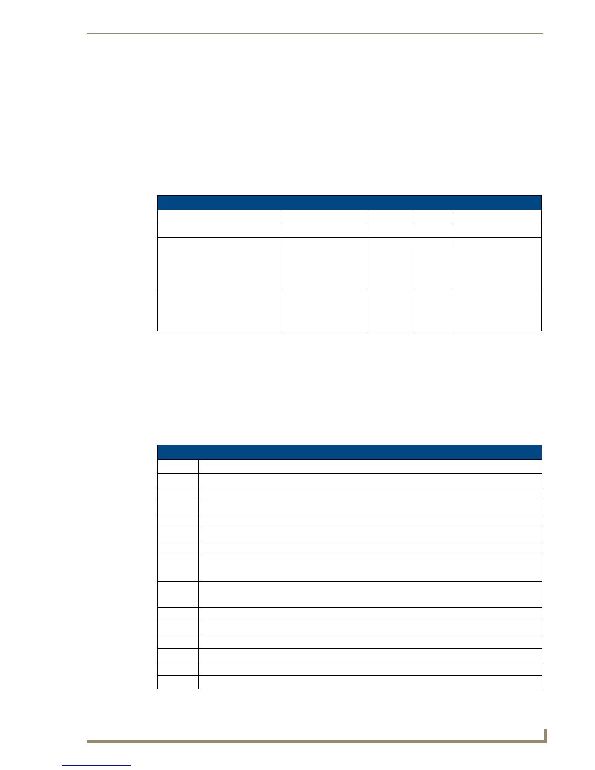
AMX Duet Module Interface Specifications
AMX Duet Module Interface Specifications
Port Mapping
This module uses multiple virtual devices in order distinguish events for one zone from another or to
distinguish one input source from another.
Input Sources use ports 1 - 8.
Rooms/Zones use ports 1 - 64.
Mi Series - Port Mapping
Virtual Device Channels Levels Control Feedback
41001:1:0 All All All All
41001:2:0 - 41001:8:0 (inputs) 1,3,9,21,22,23,27,28,
40,44,45,46,47,48,49,
81,82,225,226,255,301,
303
41001:2:0 - 41001:64:0 (rooms) 24,25,26,164,
165,166,167,
168,169,196,
199,302,304, 305,306
none ?BAND
?XCH
XCH-
1, 2,3,4,8 ?INPUT
INPUT-
BAND-
XCH-
TUNE_MODE-
TUNERPRESETSAVE
INPUT-
Channels
The UI module controls the Mi Series via channel events (NetLinx commands pulse, on, and off) sent to
the COMM module. The channels supported by the COMM module are listed below. These channels are
associated with the virtual device(s) and are independent of the channels associated with the touch panel
device. Depending on how the device is programmed each source has it’s own set of applicable
commands/channels (see the Input Source Types section on page 88).
An asterisk ( * ) indicates an extension to the standard API.
Mi Series - Channels
Channel Description
1 PULSE: Play
3 PULSE: Pause
9 PULSE: Cycle Source Power
21 PULSE: Enter Button
22 PULSE: Next Station Preset
23 PULSE: Previous Station Preset
24 ON: Ramp Volume Up – used for feedback also
OFF: Stop Ramping
25 ON: Ramp Volume Down – use for feedback also
OFF: Stop Ramping
26 PULSE: Cycle Volume Mute
27 PULSE: Set Source Power On
28 PULSE: Set Source Power Off
40 PULSE: Cycle Tuner Band
44 PULSE: Menu Button
45 PULSE: Move Menu Cursor Up
Mi Series Audio Controllers
81
Page 92

AMX Duet Module Interface Specifications
Mi Series - Channels (Cont.)
Channel Description
46 PULSE: Move Menu Cursor Down
47 PULSE: Move Menu Cursor Left
48 PULSE: Move Menu Cursor Right
49 PULSE: Select Menu Item
81 PULSE: Back Button
82 PULSE: Forward Button
164 PULSE: Increment Balance
165 PULSE: Decrement Balance
166 PULSE: Increment Bass
167 PULSE: Decrement Bass
168 PULSE: Increment Treble
169 PULSE: Decrement Treble
196 PULSE: Cycle Input Source
199 ON: Set Volume Mute On – used for feedback also
OFF: Set Volume Mute Off
225 PULSE: Increment Station
226 PULSE: Decrement Station
251 ON: Device is Online – used for feedback only
OFF: Device is not Online
252 ON: Data is Initialized – use for feedback only
OFF: Data is not Initialized
255 ON: Set source power on – used for feedback also
OFF: Set source power off
*301 ON: Tuner in Seek Mode
OFF: Tuner Seek Mode off
*302 ON: Lock Keypad
OFF: UnLock Keypad
*303 ON: Stereo Tuner mode
OFF: Mono Tuner mode
*304 ON: Room Privacy On
OFF: Room Privacy Off
*305 ON: Page Enable
OFF: Page Disable
*306 ON: Page Mute On
OFF: Page Mute Off
82
Mi Series Audio Controllers
Page 93

AMX Duet Module Interface Specifications
Levels
The UI module controls the Mi Series via level events (NetLinx command SEND_LEVEL) sent to the
COMM module. The levels supported by the COMM module are listed below. These levels are
associated with the virtual device(s) and are independent of the levels associated with the touch panel
device.
An '*' indicates an extension to the standard API.
Mi Series - Levels
Level Description
1 Volume Level (range 0…255)
2 Balance Level (range 0…255)
3 Bass Level (range 0…255)
4 Treble Level (range 0…255)
*8 Page Volume Level (range 0…255)
Command Control
The UI module controls the Mi Series via command events (NetLinx command SEND_COMMAND)
sent to the COMM module. The commands supported by the COMM module are listed below. Not all
sources will work with all the commands listed below. Depending on how the device is programmed
each source has it's own set of applicable commands/channels (see the Input Source Types section on
page 88). An '*' indicates an extension to the standard API.
Mi Series - Command Control
Command Description
?BAND Get the currently selected tuner band.
This query should be issued on the port matching the source number you want to query.
Replies with BAND-<band>
Example:
?BAND
?DEBUG Request the state of the module debug feature.
This query should be issued on port 1.
Replies with DEBUG-<value>
Example:
?DEBUG
DEBUG-<value> Set the state of debugging messages in the module.
This command should be issued on port 1.
<value>:
• 1 = set only error messages on
• 2 = set error and warning messages on
• 3 = set error, warning & info messages on
• 4 = set all messages on
Example:
DEBUG-1
?FWVERSION Get the device's firmware version.
This query should be issued on port 1.
Replies with FWVERSION-<version>
Example:
?FWVERSION
Mi Series Audio Controllers
83
Page 94

AMX Duet Module Interface Specifications
Mi Series - Command Control (Cont.)
Command Description
?INPUT Get the currently selected input source.
INPUT-<source>,<number> Set the current input source.
PASSBACK-<state> Enable or disable response reporting from the device. When
PASSTHRU-<string> Allows user the capability of sending commands directly to what-
?PROPERTY-<key> Get the value of a property <key>. If the value is not initialized, an
This query should be issued on the port matching the room number
you want to query.
Replies with INPUT-<source>,<number>
Example:
?INPUT
This command should be issued on the port matching the room/
zone you want to affect.
The <source> parameter is not used by the module due to the
device protocol and you may use it only as a place holder.
The module will select the input according to the <number> parameter.
<source> : INTERNAL TUNER,EXTERNAL TUNER, CD,
DVD, SATELLITE, DELPHI XM, AUDIO SERVER, OTHER
<number> : 1...8 = valid input source number
0 = disconnect
Example:
INPUT-INTERNAL TUNER,1 (connect to input 1)
INPUT-INTERNAL TUNER,0 (disconnect)
enabled device responses will be sent as strings to the virtual
device.
This command should be issued on port 1.
Note: By default, this is set to off at startup.
<state> : 0 = Off (default)
1 = On
Example:
PASSBACK-0
ever unit is attached with minimal processing by the Duet module.
User must be aware of the protocol implemented by the unit to use
this command. This gives the user access to features that may not
be directly supported by the module.
For more information, see the "Adding Functions to Modules" section below.
This command should be issued on port 1.
<string> : string to send to unit
Example:
PASSTHRU-MSSC1,0
empty string is returned.
This query should be issued on port 1.
<key> : SourceX (where X=1...8) = tells you what
the source is programmed as on the actual
device.
RoomsAvailable = # of rooms in the system
SourcesAvailable= # of sources available
Example:
?PROPERTY-Source2
?PROPERTY-RoomsAvailable
84
Mi Series Audio Controllers
Page 95

AMX Duet Module Interface Specifications
Mi Series - Command Control (Cont.)
Command Description
REINIT Re-initializes the communication link and data.
This command should be issued on port 1.
Note: This command deletes any messages waiting to go out to
the device.
Example:
REINIT
*TUNERPRESETSAVE-<preset>,<freq> Saves a tuner preset.
This command should be issued on the port matching the input
number.
To clear a preset use a space character as frequency.
Replies with TUNERPRESETSAVE-<preset>,<freq>
<preset> : 1...8 = valid preset range
<freq> : string = new frequency (or space to
clear)
Example:
TUNERPRESETSAVE-1,106.5
?VERSION Query for the current version number of the Duet module.
This query should be issued on port 1.
?VERSION
?XCH Get the current tuner station.
This query should be issued on the port matching the input number
you want to query.
Example:
?XCH
XCH-<station> Set the current tuner station.
This command should be issued on the port matching the input
number you want to query.
<station>: string
Example:
XCH-101.1 (for FM stations)
XCH-550 (for AM stations)
Mi Series Audio Controllers
85
Page 96

AMX Duet Module Interface Specifications
Command Feedback
The COMM module provides feedback to the User Interface module for receiver changes via command
events.
Feedback is only provided when there is a state change. If no state change resulted
from the command sent in, then no feedback will be returned.
The commands supported are listed below.
Mi Series - Command Feedback
Command Description
BAND-<band> Returns the current tuner band.
DEBUG-<value> Returns the state of debugging messages in the UI module and the Comm.
FWVERSION-<version> Returns the device's firmware version.
INPUT-<source>,<number> Returns the currently selected input source. This reply is received on the port
PRODUCT_ID-<val> Reports the current product id. This reply is received on port 1 after the module
This reply is received on the port matching the source number.
<band> : FM
AM
INVALID
Example:
BAND-FM
module.
This reply is received on port 1.
<value> : 1 = set only error messages on
2 = set error and warning messages on
3 = set error, warning and info messages on
4 = set all messages on
Example:
DEBUG-1
This reply is received on port 1.
<version> : firmware version number
Example:
FWVERSION-501
matching the room number.
<source> : INTERNAL TUNER,EXTERNAL TUNER, CD, DVD,
SATELLITE, DELPHI XM, AUDIO SERVER, OTHER,
NONE, INVALID
<number> : 1...8 = valid input source number
0 = disconnected
Example:
INPUT-INTERNAL TUNER,1
INPUT-NONE,0
is re-initialized.
<val>: string
Example:
PRODUCT_ID-M104
86
Mi Series Audio Controllers
Page 97

AMX Duet Module Interface Specifications
Mi Series - Command Feedback (Cont.)
Command Description
PROPERTY-<key>,<value> Feedback on the value of property <key>. This reply is received on port 1.
Note: An empty string is returned if the property has no value.
<key> : RoomsAvailable, SourcesAvailable, SourceX
where X=1...8
<value> : string
Example:
PROPERTY-Source3,CD
PROPERTY-Source4,Audio Server
TUNE_MODE-<val> Reports the current tuner tune mode. This reply is received on the port match-
ing the source number and is only reported if the source is an internal tuner.
<val>: 0 = Tune
1 = Seek
Example:
TUNE_MODE-0
TUNERPRESETSAVE<preset>,<freq>
VERSION-<version> Reports the version number of the module. This reply is received on port 1.
XCH-<station> Returns the current tuner station. This reply is received on the port matching the
Reports the current setting for a preset. This reply is received on the port
matching the source number.
<preset>: 1...8 = valid preset range
<freq> : string = frequency
Example:
TUNERPRESETSAVE-1,106.5
<version> : xx.yy.zz = module version number
Example:
VERSION-1.0.0
source number and is only reported if the source is an internal tuner.
<station> : string
Example:
XCH-101.1
Mi Series Audio Controllers
87
Page 98

AMX Duet Module Interface Specifications
Input Source Types
Source Commands referenced by Source Type
Other External
Tun er
225,226 45,46,47,48 45,46,47,48 45,46,47,48 45,46,47,48 225,226
40 1,3 21,49 21,49 1,3 40
303 44 44 303
22,23 22,23 22,23 22,23 22,23 22,23 22,23
9,27,
28,255
For more detailed information on the Duet Module Interface Specification, including
Device and Protocol notes, refer to the "Duet Module Interface Specification for
Matrix Audio Mi Series" document, available for download from the InConcert section
of the www.amx.com website.
9,27,
28,255
TUNERPRESETSAVE
CD Player DVD Player Satellite
Receiver
9,27,
28,255
9,27,
28,255
9,27,
28,255
Audio Server Delphi XM Internal
Tun er
301
9,27,
28,255
9,27,
28,255
9,27,
28,255
TUNERPRESETSAVE
88
Mi Series Audio Controllers
Page 99

Troubleshooting
Overview
Symptom Possible Causes Section
Everything is dead Power Power
All keypads are dead Power-cabling between MRC and keypad incorrect. Power
(No lights) Keypad connections reversed. Keypad cabling
Some keypads ok, some dead. Cabling between MRC & keypad shorted. Keypad con-
Sources don’t work manually or
automatically
Sources and keypads work but
no sound in zone.
Sources and keypads work but
no sound in zone.
Sources work manually but keypads don’t control device.
Sources power off when
selected.
Sources don’t start playing when
selected.
Troubleshooting
Keypad Cabling.
nections reversed. Defective keypad. Defective cable.
Power Power
Speakers not connected. Problem between keypad and
speakers. Problem with speakers. Volume too low.
RCA cables from source inserted into the source outputs. Source Cabling
Device programming incomplete. Infrared emitter lead
missing. Infrared emitter lead connected to wrong device.
Program error in ON/ OFF function. Programming
Program error in device select function. Programming
Restart system.
Keypad Cabling
Source Cabling
Programming.
Source cabling.
Restart system.
Power Connections
Tracking down problems that are power related are somewhat easy because the unit either powers up or
it doesn’t. If it does not, there are several things to check.
1. Check to make sure you are attached to a functioning live electrical circuit. If the branch circuit is
dead check the breaker or there may be a light switch controlling the power to the outlet. If it’s on a
switched circuit try to obtain power elsewhere.
2. Ensure that both ends of each power cord are firmly seated in all of the source components.
3. If you’re plugged into power strips, check them for operation as well. Be aware these often have
mini-breakers on them and you should check to ensure that power is functioning in EACH outlet.
It is not uncommon for the inexpensive power strips to fail at one plug-in but not the others.
4. There is a power switch located at the rear of the Controller, check to see that it is in the ON or (1)
position.
5. There is a fuse beside the power switch at the back of the Controller. Remove the fuse and inspect it
to see that it is intact. If you have an ohm meter, test for continuity across the fuse (sometimes they
look good, but they’re really broken near one of the ends). If you are using a power bar they often
have mini-breakers on them, and you should check to ensure that all is well. The fuse in the rear of
the Unit is a T8AL250v.
Mi Series Audio Controllers
89
Page 100

Troubleshooting
Source Unit Connections
Problems in source cabling can often be traced to symptoms where the source cannot be heard in any
zone and/or when the source doesn’t seem to respond to keypad commands.
1. Ensure that the source component’s LINE OUT connections are connected to the Controller’s LINE
IN connections for the correct device. These can sometimes be mismatched.
2. Take a look at the source component to ensure that MUTE functions have not accidentally been
activated.
3. Check to see that the IR emitter lead is securely fastened to the IR receiver on the source component
and that you have the lead plugged into the appropriate IR output jack. These can sometimes be
mismatched. When a keypad command is received and communicated to the source device, there is
a LED that lights on the front of the Controller indicating the processing of the command. If the
LED does not light with a keypad press, then it is possible that the device has not been programmed.
If the LED does light, there may be a problem with the IR emitter lead.
When testing IR problems, it is helpful to carry a blinking emitter or a test emitter to ensure that the
commands are being sent to the source. Techniques you can use to help isolate a sources problem
include swapping the source with another on the Controller to see if the problem stays with the
Controller or follows the movement of the source. Also try swapping IR emitter leads.
Zone Connection Problems
If there is wall power and both the source components and the Controller seem to be powering up OK,
but one or more of the zones are not working, there may be a problem at the individual zone or with the
cabling connecting to the zone. Begin by checking each zone keypad for functionality by pressing the
desired source button. The LED should light red next to the source on the KP-4e keypads or should
“wake up” with a screen menu on the touch panel keypad.
Dead Zones
There is power and the source devices and the Mi Series Controller seem to be powering up OK, but one
or more of the zones are not working.
Check each zones keypad for functionality by pressing the desired source button. The LED should light
Red next to the source.
LED Does Not light
You are not getting power and command connectivity to the zone. Check other zones and select each
source to determine if this is specific to the source or the room in general. If the problem is in a particular
room then there may be an issue with cabling to your speakers or it may be the keypad itself. If you get
similar results for a particular source in multiple zones then there may be an issue with the source
equipment and you should check to see that the selected source is ‘playing’. If every other zone is ok,
check to make sure cables to the speakers are secure and that you have tried to increase the volume level
in the zone.
Possible Causes:
Zone connectors at Mi Series Controller are not secure.
Connector at Keypad to Mi Series Controller is not secure.
Wiring standard not followed. Make certain the center two wires are in the same orientation at
the Mi Series Controller and the keypad. They may have been inadvertently reversed during
the installation.
Input and output connectors on keypad are reversed.
Keypad not recognized by system. Restart system.
90
Mi Series Audio Controllers
 Loading...