

Page 1
Installation Guide
Mi Series Audio Controllers
Overview - Mi Series Audio Controllers
The Mi Series system is an audio control and distribution system by AMX Matrix
Distributed Audio. It allows centralized control of common audio equipment, and
provides for up to 8 independently controlled music zones per chassis - each
capable of controlling the source via keypad, RS-232, IP address (Ethernet
Module), SWT Speakers (equipped with IR receivers), or the DAS-IRRX-SWT
Stealth IR receiver used with the (optional) DAS-MRC IR remote control.
Mi Series controllers consist of a centralized amplifier and control system,
controlled locally by a Keypad. Each zone may also be configured with 2 control
keypads.
Other sources such as Satellite Receivers, CD Players, MP3 Players, and any
other IR Controlled Audio Source can be patched into the RCA source inputs
located on the back panel.
Mi Series Audio Controllers are available in 120V (DAS-M0404, -M0406, M0408, -M0604, -M0606, -M0608, -M0804, -M0806, -M0808), or 240V versions
(DAS-MI0404, -MI0406, -MI0408, -MI0604, -MI0606, -MI0608, -MI0804, MI0806, -MI0808).
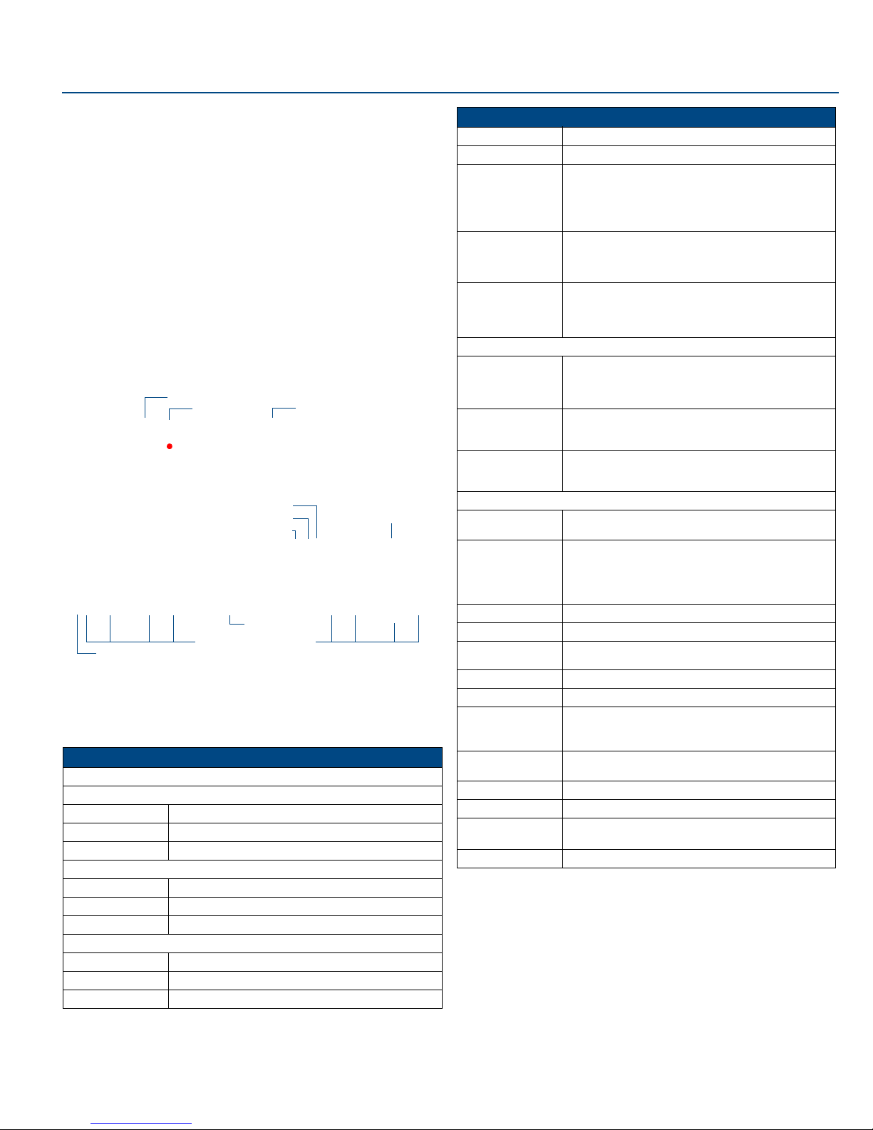
FIG. 1 illustrates the front and rear panel component layout for the Mi Series
controllers:
Navigation Buttons
IR Receiver LCD Display Screen
Expansion Port (RJ45)
RS-232
Paging IN/OUT ports
IR Outputs (6)
Zone Outputs (up to 8)
Power Switch & Receptacle
FIG. 1 Mi Series Controller Layout - Front and Rear Panel Details (DAS-M0404B shown)
Mi Series - Product Specifications
The following table provides technical specifications for the Mi Series
Controllers. Unless otherwise noted, these specifications apply to Mi Series 4, 6
and 8 Controllers.
Mi Series Product Specifications
Models Available:
Mi Series 4 Audio Controllers
• DAS-M(I)0404(B/S) 4 Source, 4 Zone Controller (black or silver, 120V or 240V)
• DAS-M(I)0406(B/S) 4 Source, 6 Zone Controller (black or silver, 120V or 240V)
• DAS-M(I)0408(B/S) 4 Source, 8 Zone Controller (black or silver, 120V or 240V)
Mi Series 6 Audio Controllers
• DAS-M(I)0604(B/S) 6 Source, 4 Zone Controller (black or silver, 120V or 240V)
• DAS-M(I)0606(B/S) 6 Source, 6 Zone Controller (black or silver, 120V or 240V)
• DAS-M(I)0608(B/S) 6 Source, 8 Zone Controller (black or silver, 120V or 240V)
Mi Series 8 Audio Controllers
• DAS-M(I)0804(B/S) 8 Source, 4 Zone Controller (black or silver, 120V or 240V)
• DAS-M(I)0806(B/S) 8 Source, 6 Zone Controller (black or silver, 120V or 240V)
• DAS-M(I)0808(B/S) 8 Source, 8 Zone Controller (black or silver, 120V or 240V)
AM/FM
Antenna Inputs
Mi Series Product Specifications (Cont.)
Stereo Output: 25 Watts/CH stereo (20Hz to 20Khz @ .1% THD)
Powe r : 960W max (Actual average usage = 300W)
Zone Support: • Eight independent Zones (4 X 2 Zone Modules).
Stereo Amplifiers: • 40 Watts/CH stereo amplifiers (20Hz to 20Khz @ .1%
Receptacle
Inputs
®
: Standard SRS/WOW® audio enhancement technology by
SRS/WOW
Front Panel Components:
• Navigation Buttons Allow for front panel programming, selection of sources, and
• IR Receiver This is where you must aim the remotes from your audio
• LCD Display Displays information necessary during the programming
Rear Panel Components:
• Power Switch &
• Paging In/Out Ports RCA jacks to connect to Paging devices (any audio input
• RJ 45 Port Ethernet Port for future expansion
• RS-232 Port 9-pin D connector to interface with NetLinx control systems.
• AM/FM Antenna
• Audio Inputs Stereo Inputs, 47K impedance, buffered.
• Audio Outputs Stereo Looping Outputs, buffered.
• IR Outputs • Mi Series 4 - Four IR 3.5mm mono output jacks.
• Zone Outputs Connections for up to 8 zone outputs that connect to the
• Expansion Port RJ 11 Port connects main Controller with Zone Expanders.
Available Colors: Black, Silver
Dimensions (HWD):
(including feet)
Weight: Max. weight with 8 zones - 31 lbs (14.06 kg)
• Each Zone is protected thermally.
• Zone grouping.
• Independent Volume, Bass, Treble, Balance and SRS
controls in each zone.
THD).
• Amplifiers are protected from overload and thermal
runaway.
SRS Labs, on all zones.
Note: SRS/WOW is a registered trademark of SRS labs,
Inc.
tuning AM/FM radio stations (when Controller is fitted with
the optional tuner board). The same array appears on the
Matrix KP-4e navigational keypad.
source components so the Controller can learn and emulate
those commands.
steps and afterward is the display to indicate information
about the source input and zone activity.
The master power switch will remain in the ON position
normally.
can be used as a paging device). The Paging device connects to the Controller via the "Paging In" connector. The
“Paging Out” connector is used to carry the page to Zone
Expander(s).
Connections for the AM and FM Antennas.
• Mi Series 6 - Six IR 3.5mm mono output jacks.
• Mi Series 8 - Eight IR 3.5mm mono output jacks.
keypads.
• 4" x 17" x 13.5"
• 10.16 cm x 43.18 cm x 34.29 cm
®
Page 2

System Integration Drawings
Using Four Conductor Speaker Wire
10-pin Ribbon Cable connecting
the KP Keypad to the
DAS-KP-NUM-G Keypad.
Wire must be straight
across (no twist)
IR OUT LINE IN
Mi Series
Controller
Shared 4-conductor keypad/speaker wire
FIG. 2 System Integration Drawing Using Four Conductor Speaker Wire
Using the Audio Zone Expander
IR OUT LINE IN
Zones 1-8
Mi Series
Controller
LINE IN RJ11
Mi Series Audio Zone Expander
FIG. 3 System Integration Drawing Using the Audio Zone Expander
Shared 4-conductor
keypad/speaker wire
RS-232 Cable
When connecting to the RS-232 port located on the back of the Mi Series
Controller, it is necessary to use a DB9 cable. The Mi Series Controller utilizes
DCE protocol therefore no NULL modem adapter is necessary. You may also
use a USB to DB9 adapter.
• Connector: DB9 Male
• Communications: 9600 Baud, 8 data bits, 1 stop bit, no parity
Keypad Installation
Connections points at the Mi Series Controller and Keypad are solder-less and
they are completed by spring-loaded Molex connectors (provided).
Note: Each zone can be configured with either 2 pushbutton keypads (Numeric
or Source), or 1 LCD Keypad and 1 pushbutton Keypad, but not 2 LCD
keypads.
Molex Wiring Connections
Looking at the rear of the Keypad with the connectors at the bottom, you will
see (2) plug type Molex connectors. Generally the mating part is already
installed on the unit when shipped. Lifting gently and pulling the connector
away from the Keypad will remove it.
The Connector on the Right Side terminates the 4 conductor wire from the Mi
Series Controller and the connector on the Left Side passes the audio to the
speakers in the zone (FIG. 4).
To Speakers
Right
Right
Left
Left
FIG. 4 KP Series Keypad: (Rear View)
Note: Ensure that wire strands do not touch neighboring wires on the
connectors, as this could result in malfunction or impede system performance.
From Controller
Right
Common
Data
Left
Source Equipment
To meet airflow and cooling requirements, place each audio source on an
individual shelf and allow a minimum of 3” clearance on the sides and top of the
unit. Stacking equipment is not recommended as this presents situations in
which airflow is restricted or component cooling may be impaired. Equipment
should have adequate room in the rear for the cables to reside.
Zone Connections
The cables that run from each of the keypads connect to the Mi Series
Controller via the same Molex connectors used at the keypads. In this case,
the connectors will not already be installed in the Mi Series Controller but will
be found in a bag in the equipment box. FIG. 5 provides a Molex Connector
Legend
Left +
DATA
FIG. 5 Molex Connector Legend
Note: When stripping cable for use with the Molex connector, only strip away
about ¼” (6mm) of the insulation from each wire. The complete assembly
should not have more than 1/32” (1mm) of bare wire exposed from the bottom
of the connector.
Right +
Ground (-)
Source Power Handling
The series Controller learns the IR commands for power on/off during the
programming setup. Source components are turned on when they are selected
on the Keypad. The source remains on until it has been idle in all zones for a
duration of 10 minutes. The source is then turned off until selected again.
Audio Component and Emitter Lead Connections
Plug the RCA audio cables from each source device into the RCA jacks
provided on the back of the Mi Series Controller. Ensure that right and left are
connected correctly. The balance setup will not image properly if reversed.
Then connect the IR emitter leads for each audio source into the appropriate
connector on the back of the Mi Series Controller, and run the optical end of the
emitter lead to the source device’s IR receiver window.
Quick Functionality Test
With all the components now wired in place you should be able to power each
zone on and off from the remote keypads. To test the system connections,
activate one zone, and manually activate one of the audio sources such as the
tuner (assuming that the programming has not yet taken place) and move
through each zone and test that keypads respond to the on/ off and volume
commands and that the source can be heard in all zones.
The basic functionality of the Mi Series Controller on/off, volume up/ down and
treble/bass/Balance/SRS® are functions performed without programming.
You may also check the status of the Keypad and what the firmware version
number is by accessing the MRC setup functions located on the front of the Mi
Series Controller.
Additional Information
Refer to the Mi Series Audio Controllers Operation/Reference Guide and Quick
Start Guide (available online at www.amx.com) for important safety
instructions, additional product information, programming instructions, and
detailed installation information.
For full warranty information, refer to the AMX Instruction Manual(s) associated with your Product(s).
©2007 AMX. All rights reserved. AMX and the AMX logo are registered trademarks of AMX.
3000 RESEARCH DRIVE, RICHARDSON, TX 75082 • 800.222.0193 • fax 469.624.7153 • technical support 800.932.6993 • www.amx.com
AMX reserves the right to alter specifications without notice at any time.
93-1101-01 REV: B
4/07
 Loading...