

Page 1

CSG SIP Communications Gateway Operation/Reference Guide
Operation/Reference Guide
SIP Communications Gateway
CSG-500, CSG-544, CSG-580
CSG
Network/Communication
Last Updated: 08/10/2011
Page 2

AMX Limited Warranty and Disclaimer
All products returned to AMX require a Return Material Authorization (RMA) number. The RMA number is
obtained from the AMX RMA Department. The RMA number must be clearly marked on the outside of each
box. The RMA is valid for a 30-day period. After the 30-day period the RMA will be cancelled. Any shipments
received not consistent with the RMA, or after the RMA is cancelled, will be refused. AMX is not responsible
for products returned without a valid RMA number.
Warranty Repair Policy
• AMX will repair any defect due to material or workmanship issues during the applicable warranty period at no cost to the AMX
Authorized Partner., provided that the AMX Authorized Partner is responsible for in-bound freight and AMX is responsible for
out-bound ground freight expenses.
• The AMX Authorized Partner must contact AMX Technical Support to validate the failure before pursuing this service.
• AMX will complete the repair and ship the product within five (5) business days after receipt of the product by AMX. The AMX
Authorized Partner will be notified if repair cannot be completed within five (5) business days.
• Products repaired will carry a ninety (90) day warranty or the balance of the remaining warranty, whichever is greater.
• Products that are returned and exhibit signs of damage or unauthorized use will be processed under the Non-Warranty Repair
Policy.
• AMX will continue to provide Warranty Repair Services for products discontinued or replaced by a Product Discontinuance
Notice.
Non-Warranty Repair Policy
• Products that do not qualify to be repaired under the Warranty Repair Policy due to age of the product or Condition of the product may be repaired utilizing this service.
• The AMX Authorized Partner must contact AMX Technical Support to validate the failure before pursuing this service.
• Non-warranty repair is a billable service.
• Products repaired under this policy will carry a ninety (90) day warranty on material and labor.
• AMX will notify the AMX Authorized Partner with the cost of repair, if cost is greater than the Standard Repair Fee, within five (5)
days of receipt.
• The AMX Authorized Partner must provide a Purchase Order or credit card number within five (5) days of notification, or the
product will be returned to the AMX Authorized Partner.
• The AMX Authorized Partner will be responsible for in-bound and out-bound freight expenses.
• Products will be repaired within ten (10) business days after AMX Authorized Partner approval is obtained.
• Non-repairable products will be returned to the AMX Authorized Partner with an explanation.
• See AMX Non-Warranty Repair Price List for minimum and Standard Repair Fees and policies.
Page 3

Safety Certification and Agency Approvals
iii
CSG SIP Communications Gateway
Safety Certification and Agency Approvals
Safety
US/CSA 60950
IEC 60950
AS/NZS 60950
EN 60950
Other
A-Tick (Australia)
CE Mark (European Union)
2002/95/EC Restrictions on Hazardous Substances (RoHS), 2005/747/EC
lead free exemption (Annex C)
Telecom
FCC Part 68, ANSI/ITA-968-A, Including Amendment A1 and A2
AS/ACIF S002
AS/ACIF S003
PTC220
EMC
FCC Part 15 Class A
EN55022/CISPR22 Class A
EN55025
IEC 61000
AS/NZS CISPR22 Class A
Page 4

Safety Certification and Agency Approvals
iv
CSG SIP Communications Gateway
Page 5

Table of Contents
v
CSG SIP Communications Gateway Operations/Reference Guide
Table of Contents
Safety Certification and Agency Approvals ....................................................... iii
Safety....................................................................................................................... iii
Other ....................................................................................................................... iii
Telecom ................................................................................................................... iii
EMC ......................................................................................................................... iii
CSG SIP Communications Gateway ....................................................................1
Overview .................................................................................................................. 1
CSG Specifications.................................................................................................... 2
CSG Interface............................................................................................................ 3
Installation ..........................................................................................................5
Unpacking the Unit ................................................................................................... 5
Inspecting Your Shipment......................................................................................... 5
Identifying Communication Ports.............................................................................. 5
Understanding the LEDs ........................................................................................... 7
Using the Configuration Reset Switch ...................................................................... 7
Pin Assignments .............................................................................................................. 8
Installing the Hardware............................................................................................. 9
Mounting the CSG .................................................................................................. 10
Instructions for Wall Mounting ...................................................................................... 10
Instructions for Wall Mounting Using DIN Rail Mounting Brackets ............................... 10
Telephone System Configuration .....................................................................15
Logging On to the CSG .......................................................................................... 15
Subsequent Logins to the CSG ..................................................................................... 15
Bonjour (Zero-Configuration) Client .............................................................................. 16
The CSG Interface................................................................................................... 17
Analog Hardware Configuration ............................................................................. 18
Advanced Analog Options ............................................................................................ 19
Trunk Configuration ...................................................................................................... 20
Analog Trunks ............................................................................................................... 21
Adding Service Providers .............................................................................................. 24
Adding VoIP Trunks....................................................................................................... 25
Outgoing Calling Rules ........................................................................................... 27
Dial Plans ................................................................................................................ 29
User Extensions ...................................................................................................... 30
Editing Multiple User Definitions .................................................................................. 33
Ring Groups............................................................................................................ 33
Page 6

vi
CSG SIP Communications Gateway Operations/Reference Guide
Table of Contents
Music on Hold ......................................................................................................... 34
Call Queues............................................................................................................. 35
Creating a Queue .......................................................................................................... 35
Agent Login Settings .............................................................................................. 37
Voice Menus ........................................................................................................... 37
Creating a Voice Menu .................................................................................................. 39
Voicemail Menu ............................................................................................................. 40
Creating the Required Voice Menus for DTMF.............................................................. 41
Record a Voice Menu.............................................................................................. 44
Time Intervals ......................................................................................................... 45
Incoming Calling Rules............................................................................................ 46
Voicemail ................................................................................................................ 48
General Settings............................................................................................................ 48
E-mail Settings .............................................................................................................. 49
SMTP Settings ............................................................................................................... 49
Paging/Intercom ..................................................................................................... 50
Conferencing .......................................................................................................... 52
Follow Me ............................................................................................................... 53
Directory................................................................................................................. 55
Call Features ........................................................................................................... 56
Feature Codes ............................................................................................................... 56
Call Parking ................................................................................................................... 58
Parking a Call ................................................................................................................ 58
Application Map ............................................................................................................ 58
Dial Options .................................................................................................................. 60
Voicemail Groups.................................................................................................... 60
System Info ............................................................................................................. 61
Networking............................................................................................................. 61
G.729 Codec........................................................................................................... 63
Backup .................................................................................................................... 64
Update.................................................................................................................... 64
Options ................................................................................................................... 66
General Preferences ...................................................................................................... 66
Language....................................................................................................................... 67
Change Password .......................................................................................................... 67
Factory Reset ................................................................................................................ 67
Reboot .......................................................................................................................... 68
Device Configuration ........................................................................................69
Touch Panel Setup Pages........................................................................................ 69
Page 7

Table of Contents
vii
CSG SIP Communications Gateway Operations/Reference Guide
Other Settings Slide Out Menu ..................................................................................... 69
Setting Up Your Touch Panel to Work with Your CSG .................................................. 71
MET-ECOM Web Console ....................................................................................... 72
Configuration Page - SIP Settings Tab .......................................................................... 73
Configuring VoIP ........................................................................................................... 74
Installing the NetLinx Module ....................................................................................... 74
Page 8

viii
CSG SIP Communications Gateway Operations/Reference Guide
Table of Contents
Page 9
CSG SIP Communications Gateway
1
CSG SIP Communications Gateway Operation/Reference Guide
CSG SIP Communications Gateway
Overview
The CSG SIP Communications Gateway is a stand alone Private Branch Exchange (PBX). It is suitable
for the desktop, or mounting in a typical network closet or restricted access location. The CSG is ideal
for small office environments or as an extension to a central CSG PBX.
The CSG can function not only as a PBX, but also as VoIP ATA, or VoIP gateway. It has eight analog
ports that can be configured (via modules) as Foreign Exchange Office (FXO) or Foreign Exchange
Station (FXS) ports.
The CSG enables you to transform an intercom-enabled Modero Touch Panel into a full-featured IP
phone. With the CSG and an intercom-enabled Modero Touch Panel you can make and receive local,
long distance, and international phone calls, and have access to phone features like call waiting, caller
ID, call forwarding, call queuing, and voice mail.
The CSG comes in three different models: the CSG-500, CSG-544, and CSG-580. The CSG-500
supports up to 50 users, but offers no analog lines. In addition to supporting up to 50 users, you can
integrate the CSG-544 and CSG-580 to outside PSTN or POTS networks. The CSG-544 allows for up to
four phones and four PSTN lines. The CSG-580 allows for up to eight PSTN lines. The CSG supports
AMX Session Initiated Protocol (SIP)-enabled touch panels—such as the MVP-8400i, MVP-5200i,
NXD-1000Vi, NXD-700Vi, and NXD-500i—and the MET-ECOM Metreau Entry Communcator, as
well as 3rd party IP phones.
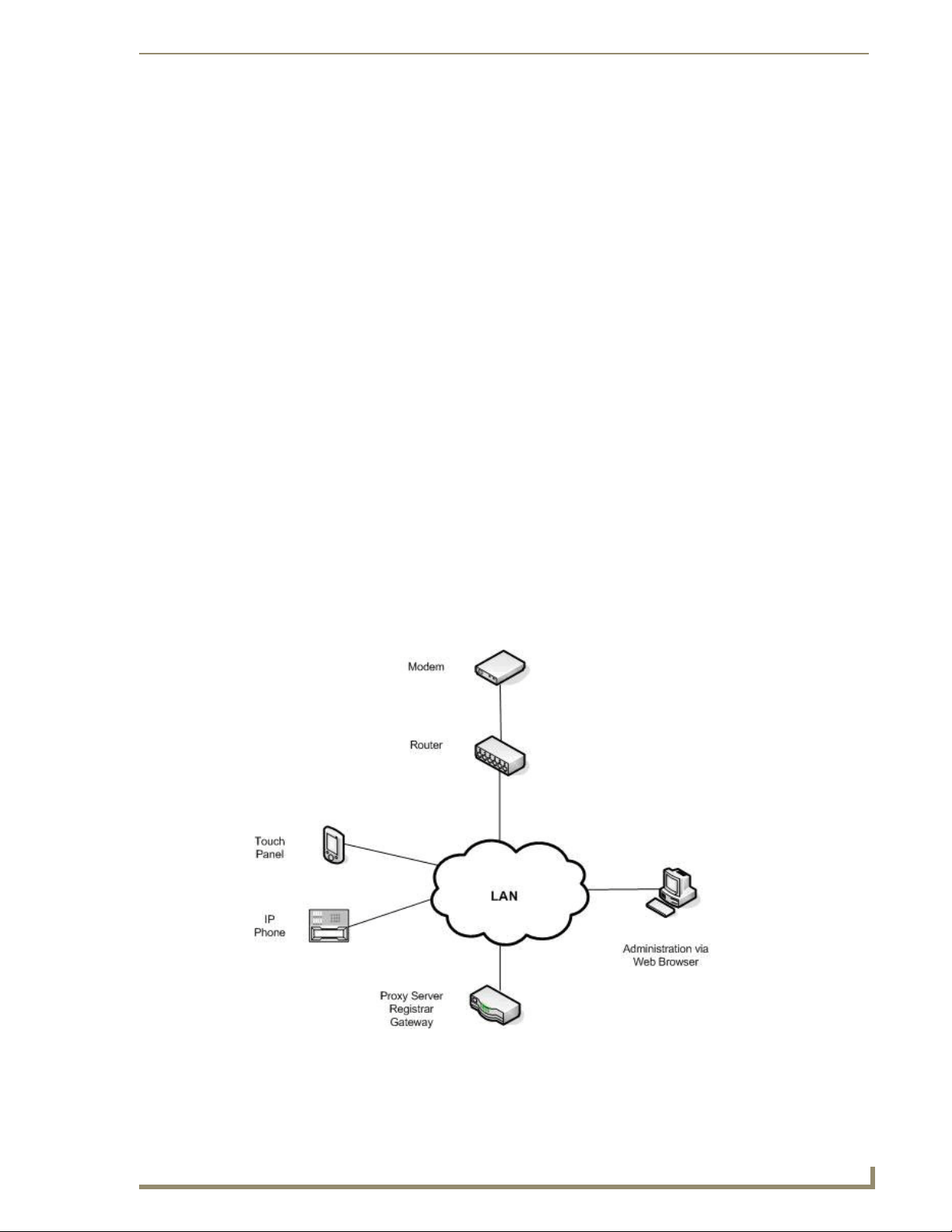
In a typical network, the CSG acts as proxy server, registrar, and gateway. A SIP-enabled touch panel
acts as a user agent, which allows the touch panel to act as an IP phone. FIG. 1 displays a high-level
diagram of the recommended network infrastructure for using the CSG.
FIG. 1 Recommended Network Infrastructure
Page 10

CSG SIP Communications Gateway
2
CSG SIP Communications Gateway Operation/Reference Guide
CSG Specifications
The following table lists the specifications for the CSG.
CSG Specifications
Dimensions (HWD): 1.74” x 11.45” x 5.44” (4.41 cm x 29.09 cm x 13.82 cm)
Weight: 2.25 lbs (1.02 kg)
Enclosure Metal with black matte finish
Power Requirements Constant current draw: 2.6 A @ 12 VDC
Memory • 8MB on board serial Flash memory
Certifications FCC (Class A), CE, IEC60950, and RoHS
Operating/Storage
Environment
Front Panel Components:
Powe r LE D Indicates whether the unit is turned on and receiving power.
Network LED Indicates whether a network cable is connected and the speed of the network.
IP Phones LEDs Indicates whether the corresponding link is connected and the speed of the
Analog LEDs Indicates whether the analog port is installed and the type of port (FXO/FXS)
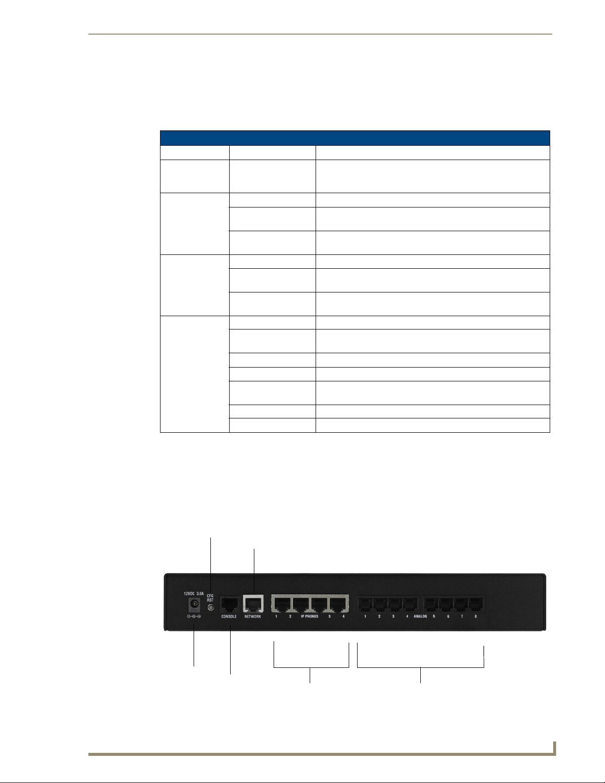
Rear Panel Components:
Power connector 5.1mm OD, 2.1mm pin, 12V 3.0A center positive
Configuration Reset Switch Resets the current configuration to the factory default when pressed
Console port 1 RJ45 port for console (craft) port serial control
Network port 1 RJ45 10/100baseT port for a general (WAN) connection
IP Phones ports 4 RJ45 10/100baseT ports for IP phone connections
Analog ports • 8 RJ11 ports: 4 for FXO and 4 for FXS connections
Compatible Devices • MVP-8400i
Included Accessories • PSN3.0 Power Supply, 3.0A, 12.0VDC (FG423-31)
Other AMX Equipment • DIN Rail Mounting Bracket (FG532-06)
• 64MB 16-bit parallel SDRAM
• Operating Temperature: 0° C (32° F) to 40° C (104° F)
• Operating Humidity: 5% to 85% RH Non-Condensing
• Storage Temperature: -20° C (-4° F) to 70° C (158° F)
• Storage Humidity: 0% to 85% RH Non-Condensing
link.
installed. (Not available on all models.)
continuously during the boot process.
(CSG-544 only)
• 8 RJ11 ports for FXO connections (CSG-580 only)
Note: The CSG-500 does not use analog ports.
• NXD-500i
• NXD-700Vi
• NXD-1000Vi
• MVP-5200i
• MET-ECOM Metreau Entry Communicator
• CSG SIP Communications Gateway Installation Guide (93-2182-01)
• 2 Surface mounting brackets (62-2182-04)
• 4 #4-40 X .250 PPH screws (80-0112)
Page 11

CSG SIP Communications Gateway
3
CSG SIP Communications Gateway Operation/Reference Guide
CSG Interface
The CSG interface enables you to create a PBX solution that rivals the features and functionality of
traditional telephony switches. Current PBX solutions are expensive and proprietary. Using the CSG,
you can replace an existing small business PBX. Since it runs on Linux, it inherits all of the power and
stability of that operating system. The CSG works with most standards-based IP telephone handsets and
software. The CSG also supports analog phones and ADSI-screen phones.
Page 12

CSG SIP Communications Gateway
4
CSG SIP Communications Gateway Operation/Reference Guide
Page 13

5
CSG SIP Communications Gateway Operation/Reference Guide
Installation
Unpacking the Unit
When you unpack your unit, carefully inspect it for any damage that may have occurred in shipment. If
damage is suspected, file a claim with the carrier and contact your reseller from which the unit was
purchased or AMX Technical Support.
Keep the original shipping container to use for future shipment or proof of damage during shipment.
Only qualified service personnel should install the unit. Users should not attempt to
perform this function themselves.
Inspecting Your Shipment
The following items are included in shipment of the CSG:
CSG unit.
Power supply (FG423-31)
CSG Installation Guide (93-2182-01)
2 Surface mounting brackets (62-2182-04)
4 #4-40 X .250 PPH screws (80-0112)
Installation
Identifying Communication Ports
The CSG unit consists of up to eight RJ11 analog ports which can be configured as either FXO or FXS
ports, depending on the type of modules installed in the CSG model. These ports provide 16ms of analog
port echo cancellation. The unit is rated for a total of 8 REN across all FXS ports. Each individual port is
rated for up to 3 REN @ 1500ft (450m).
Four 10/100BaseT LAN ports and one 10/100BaseT WAN port provide the functionality to connect to
the local network as well as allowing the CSG to act as a router. All the Ethernet ports support
auto-MDI/MDX.
An RS-232 console port is also available for additional configuring of the pre-loaded CSG software via
direct physical access. The preferred method for configuring the unit is by using the web based interface.
You can also configure it remotely using SSH. The CSG is shipped fully configured, but it may be
altered for specific applications.
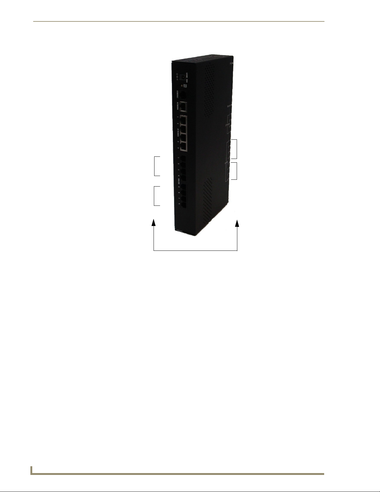
FIG. 2 displays the ports and their corresponding LEDs.
The example shown is configured with four FXO and four FXS ports, model CSG-544.
Page 14
Installation
6
CSG SIP Communications Gateway Operation/Reference Guide
FXS
FXO
FXS
FXO
Port/LED Correlation
FIG. 2 CSG - Ports/LEDs
Page 15
Installation
7
CSG SIP Communications Gateway Operation/Reference Guide
Analog ports
IP Phones ports
Network port
Config Reset
Console port
Power
Understanding the LEDs
There are 14 LEDs on the front panel of the CSG. The eight LEDs corresponding to the analog ports on
the rear panel, indicate the type of interface installed. The definition of each LED and its color
representation is explained below.
LED Definitions
LED Color Description
Power: • Blue (pulsing) On when the unit boots up after the bootload process has
completed. The LED pulses at a rate which is proportional to the
processor load.
Network: • Off No line is connected or the interface is inactive.
• Green (flashing) Link is up at 100Mbps. LED flashes at 1/10 second intervals as
traffic is detected.
• Red (flashing) Link is up at 10Mbps. LED flashes at 1/10 second intervals as
traffic is detected.
IP Phones
(4 ports):
Analog (8 ports): • Off No analog port is installed in the corresponding port.
• Off No line is connected or the interface is inactive.
• Green (flashing) Link is up at 100Mbps. LED flashes at 1/10 second intervals as
traffic is detected.
• Red (flashing) Link is up at 10Mbps. LED flashes at 1/10 second intervals as
traffic is detected.
• Green (solid) Port is configured for FXS operation and is enabled. An analog
telephone may be connected to this port.
• Green (flashing) Telephone is ringing.
• Green (slow blinking) Telephone is in use.
• Red (solid) Port is configured for FXO operation and is enabled. A telephone
line may be connected to this port.
• Red (flashing) Telephone line is ringing.
• Red (slow blinking) Telephone line is in use.
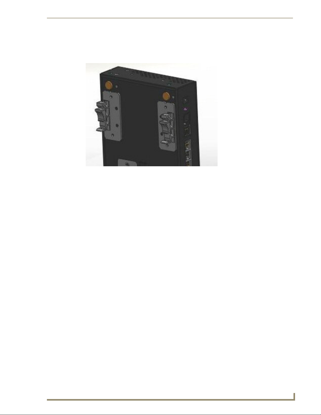
Using the Configuration Reset Switch
The Configuration Reset (CFG RST) switch (rear panel - see FIG. 3) resets the current configuration to
the factory defaults when pressed. The switch must be continuously pressed during the boot process.
This will force the unit to delete all configuration data.
FIG. 3
Rear panel connectors
Page 16
Installation
8
CSG SIP Communications Gateway Operation/Reference Guide
If you press the RST CFG button, you to lose all configuration settings.
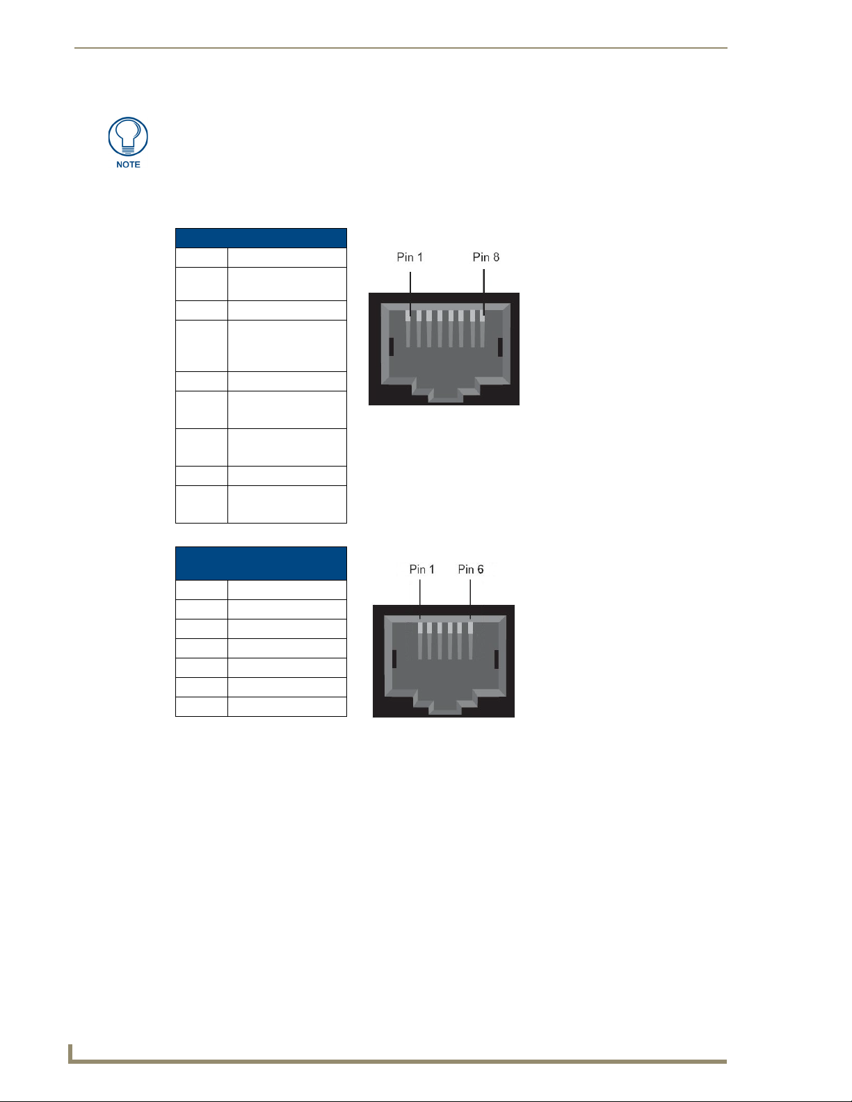
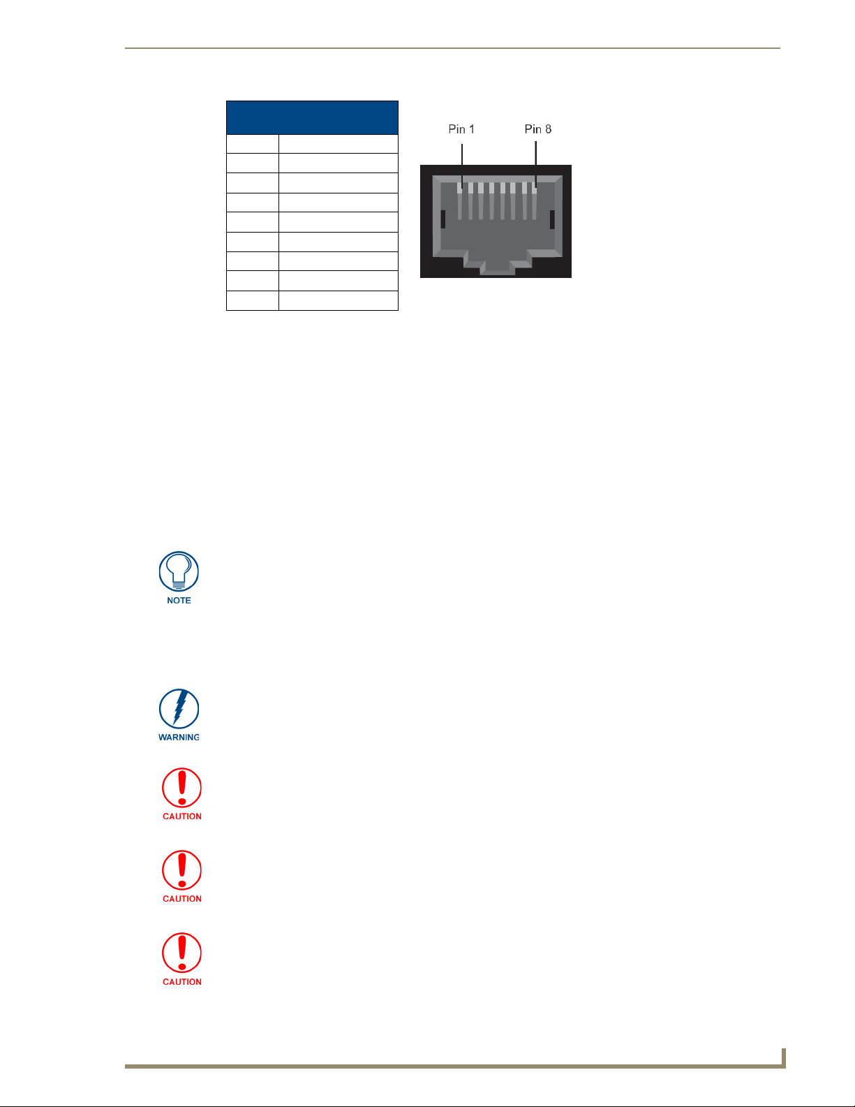
Pin Assignments
The following tables describe the pin assignments for the different ports on the CSG.
Console Port Pinouts
Pin Description
1 Ground (Connect to
DB9 pin 5)
2 Unused (Leave Open)
3 Primary RxD (To
CSG)
Connect to DB9 Pin 3
4 Unused
5 Tx (From CSG)
Connect to DB9 Pin 2
6 CTS (To CSG)
Connect to DB9 Pin 7
7 Open
8 RTS (From CSG)
Connect to DB9 Pin 8
RJ11 Analog Port Connector
Pinouts
Pin Description
1 Unused
2 Unused
3 Tip
4 Ring
5 Unused
6 Unused
Page 17
Installation
9
CSG SIP Communications Gateway Operation/Reference Guide
IP Phone and Network
Ethernet Port Pinouts
Pin Description
1 Rx Receive Negative
2 Rx Receive Positive
3 Tx Transmit Negative
4 Unused
5 Unused
6 Tx Transmit Positive
7 Unused
8 Unused
Installing the Hardware
1. Connect an Ethernet cable connected to your network to the Network port on the back of the CSG.
2. Connect an Ethernet cable an IP Phone port. This will be used during the initial configuration of the
CSG.
3. Connect the provided power supply to the unit’s DC connector. The unit immediately receives
power once you connect a power source to it.
4. When the unit completes the boot process, the left-most eight LEDs indicate how the analog ports
are configured. A red light indicates the port is FXO, and a green light indicates the port is FXS. If
the light for a port is off, the port is not installed.
The analog port configuration is selected when purchasing your CSG unit.
5. Connect telephones to the analog ports that are configured as FXS ports and connect phone lines to
the analog ports that are configured as FXO ports. If you are using the CSG-500, you can skip this
step.
If you are using the CSG-544, do NOT connect analog ports 1-4 to a phone line.
Since both the FXS ports and the phone lines supply power, the hardware could
sustain damage. This damage is not covered under the AMX standard warranty.
This unit must be connected to the Telecommunications Network in your country
using an approved line cord, e.g.: for Australia use only line cords complying with
ACA Technical Standard TS008.
This unit must be connected only to the appropriate Telecommunications Network
port (as approved for use in your specific country).
To reduce the risk of fire, use only No. 26 AWG or larger telecommunication wiring for
network connections.
Page 18
Installation
10
CSG SIP Communications Gateway Operation/Reference Guide
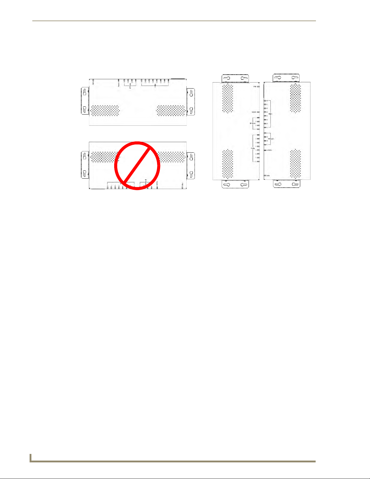
LEDs pointing UP
DO NOT point the LEDs DOWN
LEDs pointing SIDEWAYS
Mounting the CSG
FIG. 4 illustrates the proper mounting installation options for wall mounting the unit:
FIG. 4 Acceptable Mounting Orientation options (wall mounting)
Instructions for Wall Mounting
Select the area to mount the CSG unit (refer to FIG. 4). The unit should be mounted at or below eye
1.
level to properly view the LEDs.
2. Line up one of the surface mounting brackets with the two holes on one side of the CSG. Install two
#4-40 X .250 PPH screws into the holes in the bracket to secure the bracket to the CSG.
3. Repeat step 2 to attach the second bracket to the other side of the unit.
4. Affix one screw to the wall. Leave approximately 1/4-inch of the screw protruding from the wall to
allow the head of the screw to slide into the settings on the mounting bracket, mounting the unit to
the wall.
5. Repeat step 4 to attach the second bracket to the wall.
Instructions for Wall Mounting Using DIN Rail Mounting Brackets
The AC-DIN-CS3 DIN Rail Mounting Brackets (FG532-06) allow you to install the CSG on a standard
DIN rail (or “top-hat” rail). The DIN Rail Mounting Bracket comes in a kit that includes everything you
need to mount a single device on a standard (35 MM. wide) metal DIN rail. Follow these steps to mount
the CSG using the DIN rail mounting brackets:
1. Use the four supplied flat-head screws to secure the DIN mounting clips to the bracket.
2. Use the two supplied pan-head screws to secure the bracket/mounting clip assembly to the CSG.
Use the mounting holes on either side panel of the enclosure to mount the bracket/mounting clip
assembly.
3. Snap the bracket/clamp onto the DIN rail.
Page 19
Installation
11
CSG SIP Communications Gateway Operation/Reference Guide
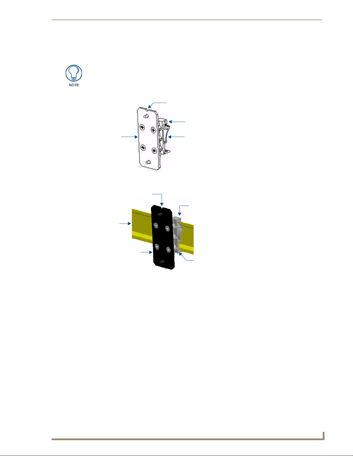
Notch indicates top of the bracket
Bracket DIN Mounting Clips
(2 per bracket)
Drilled holes indicate
top of the clip
DIN Rail
DIN Mounting Clip
attached to the bracket
Bracket
(mounts to the CSG)
This notch indicates
These two holes indicate
the top of the bracket
the top of the mounting
clips
(2 clips per bracket)
(35mm)
There are indicators on both the bracket and the mounting clips to show which end is the “top” to ensure
correct mounting orientation (see FIG. 5).
The bracket has a notched side to indicate the top of the piece. The DIN mounting
clips also have two holes drilled in the top portion of the clips that indicate the top of
the clip.
FIG. 5 AC-DIN-CS3 - Clip/Bracket assembly (attach to CSG)
FIG. 6 illustrates the correct mounting orientation of the DIN Rail Mounting Bracket:
FIG. 6 AC-DIN-CS3 DIN Rail Mounting Bracket - mounted on a DIN rail
Page 20
Installation
12
CSG SIP Communications Gateway Operation/Reference Guide
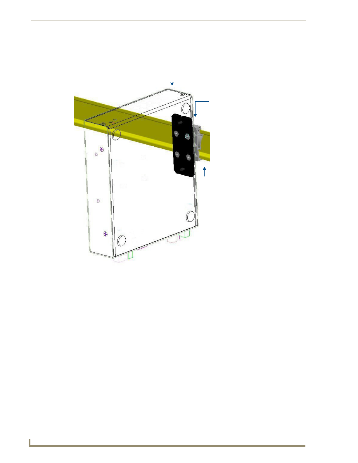
Mounted Device
(front panel facing UP)
Bracket/Clamp
assembly
mounted to
device
DIN Rail
Note: Mount devices
with visual indicator
(LCD displays, LEDs)
facing up, for ease of use.
FIG. 7 illustrates the correct mounting orientation of the DIN Rail Mounting Bracket and the orientation
of the mounted device.
FIG. 7 Device mounted on a DIN rail using the DIN Rail Mounting Bracket kit
Page 21
Installation
13
CSG SIP Communications Gateway Operation/Reference Guide
You can also mount the CSG by attaching the mounting brackets to the bottom of the unit. FIG. 8
displays the CSG with mounting brackets attached to its underside. The bracket clamps attach to the DIN
rail as shown in FIG. 6.
FIG. 8 DIN Rail Mounting Brackets attached to the bottom of the CSG unit
Page 22

Installation
14
CSG SIP Communications Gateway Operation/Reference Guide
Page 23
15
CSG SIP Communications Gateway Operation/Reference Guide
Telephone System Configuration
This chapter provides information on how to initially set up your telephone system via the CSG Interface. The
CSG Interface gives you the ability to set up your telephone system without the need to use command line
configuration. After connecting to the CSG, the primary menu is displayed, giving you the ability to configure
your system, as well as add features to your call system as your needs change.
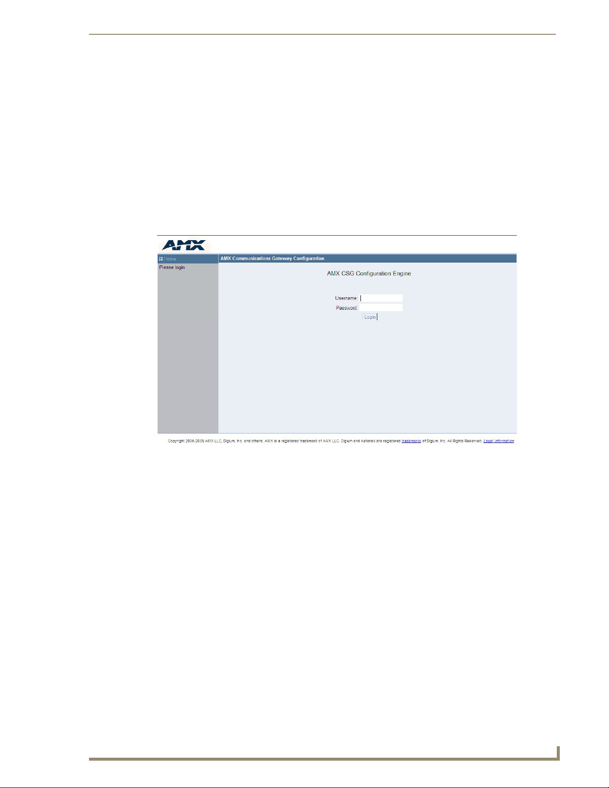
Logging On to the CSG
Your CSG should already be connected to an internet or network connection, as described in the Installing the
Hardware section on page 9. In the address field of a CSG supported web browser, enter the IP address
assigned to your CSG. The default LAN IP address is 192.168.69.1.
Telephone System Configuration
FIG. 9 CSG Interface Login
To log on to the system enter the following credentials:
Username: admin
Password: <password>
The first time you log on you will be prompted to change your password from the default. You should have
already chosen a new password during the installation process. Once the log on process is complete the CSG
Interface home page will be displayed.
Subsequent Logins to the CSG
The method described above will work to log onto the configuration tool of the CSG. In addition, you
can log onto the CSG using the CSG's Network port once it has been enabled. In this case, open a web
browser on a computer which is located on the same network as the CSG. In the address field of the web
browser, enter the IP address of the CSG as defined during the initial installation.
Page 24
Telephone System Configuration
16
CSG SIP Communications Gateway Operation/Reference Guide
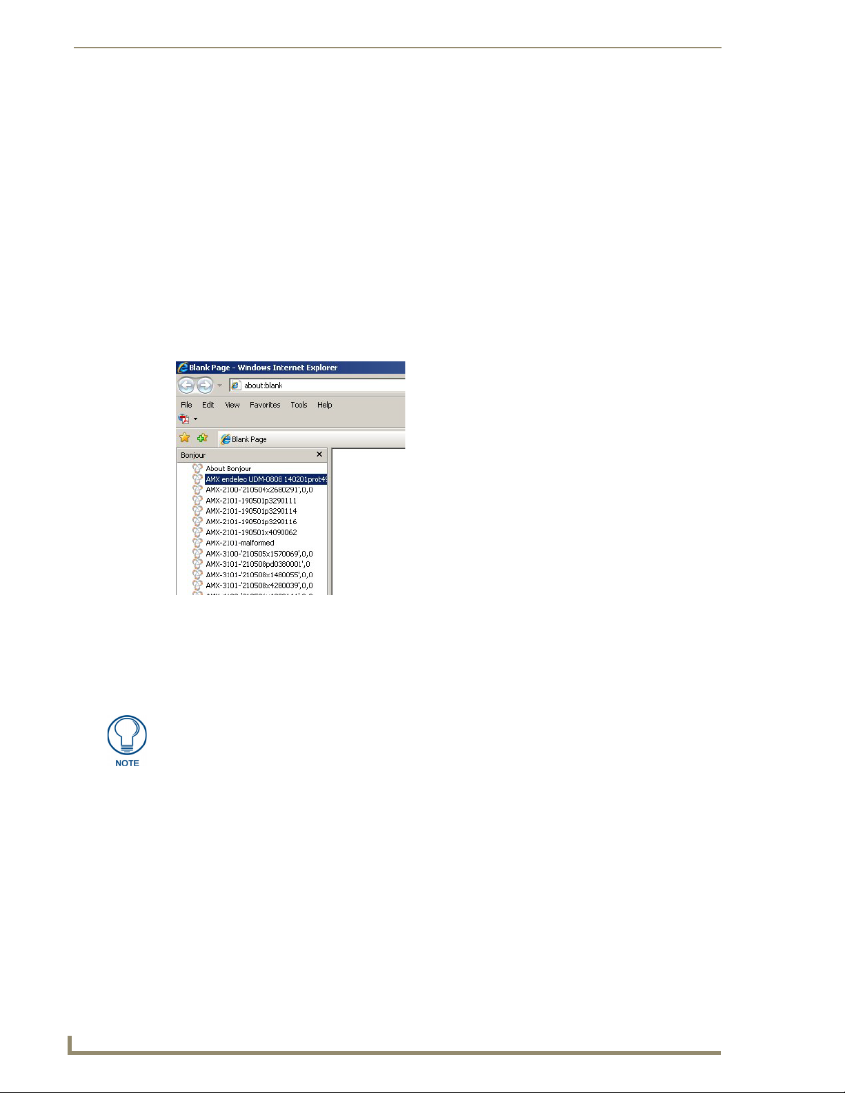
Bonjour (Zero-Configuration) Client
You can also log on to the CSG by using a zero-configuration networking client that allows you to determine
the unit’s IP address, such as Bonjour or a similar zero-configuration client. Zero-configuration (or Zeroconf,
also known as "Bonjour") technology provides a general method to discover services on a local area network.
In essence, it allows you to set up a network without any configuration, as described below.
You may need a zero-configuration client to determine the IP address of the CSG. There are many
zero-configuration clients available. However, for the purposes of this document, we will refer to Bonjour for
Windows. It is free, and widely available for download. If you don’t already have it installed on your PC,
download and install Bonjour for Windows before you begin.
Perform these steps to log on to the CSG through Bonjour for Windows:
1. With Bonjour for Windows running on a PC that has access to the LAN on which the CSG resides,
connect the CSG to the network (see the Installing the Hardware section on page 9.)
2. In Bonjour, you will see the unit join the network at power up (FIG. 10). Double-click the CSG link
to access the CSG Login page (FIG. 9).
FIG. 10 Bonjour for Windows - screen
3. To log on to the system, enter the following user name and password:
Username: admin
Password: 1988
As shown in FIG. 10, Bonjour for Windows operates as a plug-in to Internet Explorer
(version 7 shown), and is displayed in the IE Explorer Bar. If you have installed
Bonjour for Windows, but don’t see the Bonjour toolbar icon, you may need to
"unlock" and expand the toolbars to see it.
Page 25
Telephone System Configuration
17
CSG SIP Communications Gateway Operation/Reference Guide
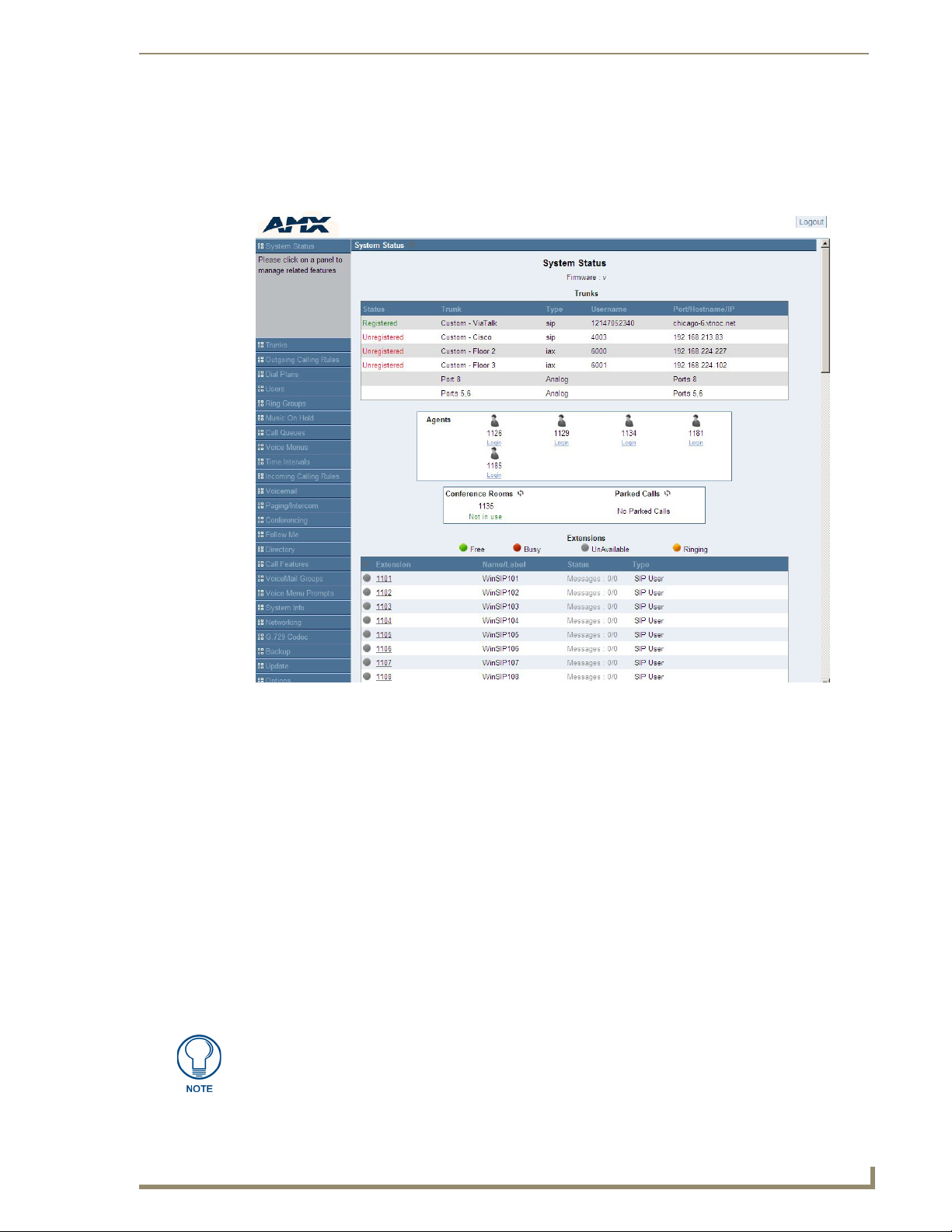
The CSG Interface
The CSG Interface gives you the ability to configure the basic hardware and dial plan elements you need when
initially setting up your system. You must create trunks, system users, conferencing, voice mail, etc. After
logging into the CSG Interface, you’re presented with a variety of options on the left side of the page.
FIG. 11 System Status Page
The CSG Interface supports the following browsers:
Firefox 1.5 through 3.0
IE 7
Safari 3.x
Opera 9.x
Every page of the CSG Interface has two columns. The left column identifies all the elements for which you
can program the CSG. The elements listed begin with System Status, which is the first page you see upon
logon, and proceed down to Options. Clicking any of the tabs on the left of the page opens the corresponding
page in the right column. Many pages have additional information. Click on the information symbol, a blue “i”
enclosed in a circle, to get more information about a field or page.
The System Status page is the default page. This page shows you the current version of firmware you are
using, the status of any trunk lines you have configured, the realtime status and additional details of all user
extensions, including the new and old voicemail message count for each user extension (e.g. Messages: new/
old), and the realtime status of all agents, conference rooms, and parked calls. You can click on most extension
definitions to get more information. In addition, the System Status page gives you the ability to log in, log out,
pause, and unpause an agent that is associated with one or more call queues.
A user extension will have the status of “Unavailable” when the VoIP account
associated with it is not registered to the CSG. The status will not change to
“Unavailable” when a user extension has both an analog port and a VoIP account
associated with it.
Page 26
Telephone System Configuration
18
CSG SIP Communications Gateway Operation/Reference Guide
In the upper right corner of each page you will see the Apply Changes and Logout buttons. Click Apply
Changes to save and activate any changes you have made on a page so that you can utilize the changes. Click
Logout on any page to exit the CSG Interface.
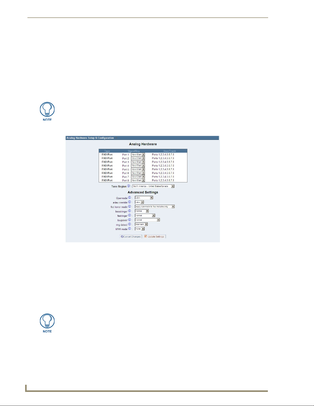
Analog Hardware Configuration
You must configure your analog hardware according to the needs of your system as part of your initial CSG
configuration. The Configure Hardware page gives you the ability to configure both your FXS and FXO
ports, as well as your Tone Region, operation mode, message waiting indicator mode (MWI), etc. The number
of FXS and FXO ports available for configuration will depend on the CSG model you purchased. Click the
Configure Hardware tab to configure your analog hardware.
The Configure Hardware tab will not be available if you ordered a VoIP only model.
FIG. 12 displays the Configure Hardware page.
FIG. 12 Configure Hardware
FXS and FXO ports provide the ability to receive and send calls through the traditional telephone network, or
POTS (Plain Old Telephone System). FXS modules provide both dial tone and ringing voltage to an analog
phone. FXO modules accept dial tone and provide an interface to the traditional phone lines. You plug a
telephone line into an FXO port, and an analog telphone into an FXS port.
On this page you can specify the signalling type for your FXS and FXO ports. You have two choices; either
Kewl Start or Loop Start. The Loop Start method uses a short to request a dial tone. All North American home
phone lines use loop start signalling. Kewl Start is the same as Loop Start, but is better able to detect
disconnects. Select either Kewl Start or Loop Start for each FXS and FXO module. Kewl Start is the default
and is preferred for analog circuits in the CSG.
Ground Start signalling is not supported.
You also need to select a tone region, which defines the set of tones (dial tones, ringing tone, busy tone, etc)
used in your region. Select your country, or the nearest neighboring country, from the Tone Region drop-down
list. The default setting is North America (United States/Canada).
Page 27

Telephone System Configuration
19
CSG SIP Communications Gateway Operation/Reference Guide
Advanced Analog Options
There are also some advanced settings which are applied to your analog hardware. Specify them as needed, or
accept the default values.
Advanced Analog Options
Option Description
Opermode Setting operation mode, or Opermode, sets the On Hook Speed,
a-law Override This option enables you to set the audio compression scheme.
fxs Honor Mode This option enables you to choose whether you apply the
Boost Ringer This option enables you to set the voltage used for ringing an
Fast Ringer This option enables you to set the fast ringer tone to normal or to
Low Power This option enables you to set the low power to normal or to a fast
Ring Detect This option enables you to select the ring detect mode. Users
MWI Mode This option enables you to specify the type of Message Waiting
Ringer Impedance, Ringer Threshold, Current limiting, Tip/Ring
voltage adjustment, Minimum Operational Loop current, and and
AC Impedance selection as predefined for each countries analog
line characteristics. Select the country in which your CSG is operating.
The setting you choose is dependent on the country of operation.
U-law is used in the United States and Canada. A-law is used in
most other countries. If possible, confirm the scheme which is
best for operation of your CSG.
opermode setting to your FXO modules only, or to both FXS and
FXO modules.
analog phone. You can choose from normal and peek(89V).
Normal sets the ring voltage to a normal level. Peek sets the
voltage to 89v.
a 25Hz tone.
ringer peak of 50v.
who are experiencing trouble detecting caller ID from analog
service providers or whose lines exhibit a polarity reversal before
the provider transmits caller ID should select Full Wave.
Otherwise, choose Standard.
Indicator detection to be done on trunk (FXO) interfaces. The
options are None, which performs no detection, FSK, which
performs Frequency Shift Key detection, or NEON, which perform
Neon MWI detection. The default value is None.
Page 28

Telephone System Configuration
20
CSG SIP Communications Gateway Operation/Reference Guide
Advanced Analog Options (Cont.)
Echo
Cancellation NLP
Type
Echo
Cancellation NLP
Threshold
Echo
Cancellation NLP
Max Suppression
This option enables you to specify the type of Non Linear
Processor (NLP) you want applied to the post echo-cancelled
audio reflections received from analog connections. There are
several options:
• None - This setting disables NLP processing and is not a
recommended setting. Under most circumstances, choosing
None will cause some residual echo.
• Mute - This setting causes the NLP to mute inbound audio
streams while a user connected to the appliance is speaking.
For users in quiet environments, Mute may be acceptable.
• Random Noise - This setting causes the NLP to inject random
noise to mask the echo reflection. For users in normal
environments, Random Noise may be acceptable.
• Hoth Noise - This setting causes the NLP to inject a low-end
Gaussian noise with a frequency spectrum similar to voice. For
users in normal environments, Hoth Noise may be acceptable.
• Suppression NLP - This setting causes the NLP to suppress
echo reflections by reducing the amplitude of their volume.
Suppression may be used in combination with the Echo
cancellation NLP Max Suppression option. For users in loud
environments, Suppression NLP may be the best option. This is
the default setting for the Echo Cancellation NLP Type option.
This option enables you to specify the threshold difference, in dB,
between the received audio (post echo cancellation) and the
transmitted audio, at which time you want the NLP to engage.
The default setting is 24 dB.
This option, only functional when the Echo Cancellation NLP
Type option is set to Suppression NLP, specifies the maximum
amount of dB that the NLP should attenuate the residual echo.
Lower numbers mean that the NLP will provide less suppression
(the residual echo will sound louder). Higher numbers, especially
those approaching or equaling the Echo Cancellation NLP
Threshold option, will nearly mute the residual echo. The default
setting is 24 dB.
The VPM Settings section will not be visible on older hardware revisions of the CSG.
Once you have made the configuration changes to your hardware which you require, click Save Changes. A
message will display letting you know that for these changes to be completed, you must reboot your CSG.
Click Options on the left menu, select the Reboot tab, and then click Reboot Now to reboot your appliance.
Rebooting your CSG will terminate any active calls.
Trunk Configuration
Now that you have configured your analog hardware (assuming your unit had any) you are ready to set up your
trunk lines. Trunks are outbound lines used to make calls. Trunks can be either analog or VoIP. Click Trunks
from the main menu to access the trunk configuration page.
FIG. 13 Trunk Configuration Page
Page 29

Telephone System Configuration
21
CSG SIP Communications Gateway Operation/Reference Guide
Trunk definitions are used in calling rules, dial plans, and call routing, etc. You can use a mixture of both
analog and VoIP trunks.
Analog Trunks
Select the Analog Trunks tab to access the Manage Analog Trunks page. Here you can create an analog
trunk definition for each analog port on your CSG. Click New Analog Trunk to open the New Analog Trunk
definition page.
FIG. 14 New Analog Trink Definition
The following options appear on the New Analog Trunk page:
New Analog Trunk Page Options
Option Description
Channels Select one or more analog channel (port) to be associated with
Trunk Name Specify a unique name to help you identify this trunk when it is
Busy Detection This setting is used to detect far end hangup or for detecting busy
Busy Count If Busy Detection is enabled it is also possible to specify how
Busy Pattern If Busy Detection is enabled, it is also possible to specify the
Ring Timeout Trunk (FXO) devices must have a timeout to determine if there
this trunk.
referred to in other areas such as calling rules.
signal. Select Yes to enable this feature.
many busy tones to wait for before hanging up. The default is 4,
but better results may be achieved by setting to 6 or 8. The higher
the number, the longer it will take to hangup a channel. A higher
number also lowers the possibility of false detections.
cadence of your busy signal. In many countries it is 500
milliseconds on, 500 milliseconds off. Without Busy Pattern
specified, the CSG will accept any regular sound-silence pattern
that repeats multiple times as a busy signal. If you specify Busy
Pattern, then the CSG will check the length of the sound (tone)
and silence, which will further reduce the chance of a false
positive.
was a hangup before the line was answered. This value can be
configured to shorten how long it takes before the CSG considers
a non-ringing line to have hung up.
Page 30

Telephone System Configuration
22
CSG SIP Communications Gateway Operation/Reference Guide
New Trunk Analog Page Options (Cont.)
Answer on
Polarity Switch
Hangup on
Polarity Switch
Call Progress On trunk interfaces it can be useful to follow the progress of a call
Progress Zone This option defines the call progress zone for the trunk interfaces.
Use CallerID If this option is enabled Caller ID detection is also enabled.
Caller ID Start This option allows one to define the start of a caller ID signal.
Caller ID This option allows the lines to report the caller ID string as
Pulse Dial If this option is enabled, pulse dialing, instead of DTMF, will be
CID Signalling This option defines the type of caller ID signalling to use.
Mailbox This setting allows any message waiting indicator received
Flash Timing Flash Timing defines the duration, in milliseconds, that the CSG
Receive Flash
Timing
If this option is enabled the reception of a polarity reversal will
mark when an outgoing call is answered by the remote party.
In some countries, a polarity reversal is used to signal the
disconnect (or hang up) on a phone line. If the Hangup on Polarity
Switch option is enabled, the call will be considered “hung up” on
a polarity reversal.
through Ringing, Busy, and Answering. If turned on, Call Progress
attempts to determine answer, busy, and ringing on phone lines.
This feature is highly experimental and can easily detect false
answers and hang-ups. This may cause a hang up during the
middle of a call. Few zones are supported, but can be selected
with the Progress Zone option.
Select Ring from the drop-down list to start caller ID when a ring
is received, or Polarity, to start caller ID when a polarity reversal is
detected.
received from the telco, or as a fixed value by using the advanced
option.
used.
• bell - Bell202 as used in the United States
• v23 - Used in the UK
• v23_jp - Used in Japan
• dtmf - Used in Denmark, Sweden, and Holland
across the associated trunk to be forwarded to a local User, such
as a SIP phone.
will use if it is sending a flash signal to another system.
Receive Flash Timing defines the duration, in milliseconds, that
the CSG requires to consider a flash operation it receives to be
valid.
Once you have completed the Analog Trunk definition, click Add. A message will display letting you know
that for these changes to be completed, you must reboot your CSG. Before doing so, you may wish to click the
Edit button associated with an analog trunk to configure additional options for tuning the audio.
Page 31

Telephone System Configuration
23
CSG SIP Communications Gateway Operation/Reference Guide
FIG. 15 Edit Analog Trunk
The Audio Tuning section will allow you to calibrate your analog ports for optimum performance. Please
ensure that your analog lines are plugged in before clicking the Easy Calibrate button. Your CSG must not
have any active calls for the calibration process to complete successfully on all analog ports. If you wish to
reset the calibration, click the Reset Calibration button.
The Easy Calibration feature can take approximately 90 seconds per port to
complete.
In addition, an option to configure the gain level for each port will be listed. This option can be used to raise or
lower the audio level on your ports. Normally, you should not have to adjust your analog ports beyond the
initial calibration. Should you still need to fine tune your audio settings, please select one of the following:
Low
Soft
Normal
Loud
Louder
Once you have completed the Analog Trunk definition, click Update. For these changes to be completed, you
must reboot your CSG. Click Options on the left menu, select the Reboot tab, and then click Reboot Now to
reboot your appliance. Rebooting your CSG will terminate any active calls.
Page 32

Telephone System Configuration
24
CSG SIP Communications Gateway Operation/Reference Guide
Adding Service Providers
You must configure a VoIP service provider to connect to the Public Switched Telephone Network (PSTN) via
a VoIP connection. Access to the PSTN gives you the ability to place calls to telephone numbers no matter
how they connect to the PSTN (VoIP or standard analog system). Click the Service Providers tab to add a
VoIP (SIP or IAX) service provider.
FIG. 16 Add New Service Provider
The list of VoIP service providers and corresponding configuration information is pulled dynamically from a
secure AMX webservice. If you are already a VoIP provider customer, select the provider from the list, click
Add, and input your user name and password. Once you have added a service provider it will appear in the
Service Providers list. There are Edit and Delete buttons associated with each Service Provider listing. Click
Edit to further refine your service provider definition. A detailed definition will be displayed.
FIG. 17 Edit VoIP Service Provider
The Edit Service Provider page gives you the ability to change your caller ID, as well as select a range of
codecs.
Edit Service Provider Page Options
Option Description
Username/
Password
Caller ID The caller ID sent to the PSTN will be set to the value specified in
Codecs Codecs provide the ability for your voice to be converted to a
You will need to provide your log on credentials to update your
service provider information.
this field.
digital signal and transmitted across the Internet. The quality of
your call can be affected by the choice you make. The codecs
available to you will depend on what is supported by the service
provider you choose. You can select the order in which the
codecs are used. The codecs commonly available are u-law,
a-law, GSM, G.726, G.722, and G.729A. A registered G.729A
license is required to use the G.729A codec.
Click Update when you have completed your changes, or Cancel to discard your changes.
Page 33

Telephone System Configuration
25
CSG SIP Communications Gateway Operation/Reference Guide
Adding VoIP Trunks
If you do not have a subscription with one of the VoIP providers listed above, or you have a special VoIP setup,
you can add a custom VoIP trunk. Click the VoIP Trunks tab to add a VoIP (SIP or IAX) service provider. The
Create New SIP/IAX Trunk page will be displayed.
FIG. 18 Create New SIP/IAX Trunk Definition
Fill in the initial SIP/IAX trunk definition with the following information:
Create New SIP/IAX Trunk Page Options
Option Description
Type Select either the SIP or IAX protocol:
• SIP - Identifies that the trunk sends and receives calls using the
VoIP protocol SIP.
• IAX - Identifies that the trunk sends and receives calls using the
VoIP protocol IAX.
Provider Name The hostname or IP address assigned to the VoIP provider or
server.
Username/
Password
You will need to provide your log on credentials to the VoIP trunk
server.
Note: If your VoIP trunk does not require a username, you may
leave the username field blank.
Click Add once you have completed your definition, or Cancel to discard your changes.
Once you have added a VoIP trunk it will appear in the SIP/IAX trunks list. There are Edit and Delete buttons
associated with each VoIP trunk listing. Click Edit to further refine your trunk definition.
FIG. 19
Edit VoIP Trunk
Page 34

Telephone System Configuration
26
CSG SIP Communications Gateway Operation/Reference Guide
The following options will be available:
Edit VoIP Trunk Page Options
Option Description
Provider Name Enter a unique name to help you identify this trunk for use in
Hostname The hostname or IP address assigned to the VoIP provider or
Username/
Password
Codecs Codecs provide the ability for your voice to be converted to a
Caller ID This is the number the trunk will try to use when making outbound
From Domain If required by your provider, specify your primary domain identity
From User If required by your provider, specify the user to show in the user
Insecure This is a SIP parameter used to determine peer matching. The
Enable Remote
MWI
calling rules, etc.
server.
You will need to provide your log on credentials to update your
service provider information.
digital signal and transmitted across the Internet. The quality of
your call can be affected by the choice you make. The codecs
available to you will depend on what is supported by the service
provider you choose. You can select the order in which the
codecs are used. The codecs commonly available are u-law,
a-law, GSM, G.726, G.722, and G.729A. A registered G.729A
license is required to use the G.729A codec.
calls. For some providers it is not possible to set the CallerID with
this option. Thus this option may be ignored. When making
outbound calls the following rules are used to determine which
Caller ID is used, if they exist:
• The first Caller ID used is the Global CID defined in the Options
tab.
• The Caller ID set in the VoIP Trunks configuration, if defined,
takes precedence over the Global CID.
• The Caller ID set for the user making the call as defined in the
Users page will take precedence over the Global CID and the
CID set in VoIP trunks.
to show in the domain field of the From header for outgoing SIP
invites. Otherwise, only your IP address will be sent in the From
header.
field of the From header for outgoing SIP invites. Otherwise, only
your IP address will be sent in the From header.
setting determines whether or not an insecure connection will be
allowed, or if authentication is required. The valid options are:
• port - Enter this value to match against only an IP address. This
setting is useful if you have multiple endpoints behind a NAT
device.
• very - Specify this value if you do not want to require
authentication upon an initial invite.
• no - Specify this value if you do not want to allow an insecure
connection.
When you select this option, you enable voicemail from your
remote provider. Typically a user’s voicemail is stored locally on
the CSG. The notification of new voice mail is provided by the
same local CSG. If you would like to receive voicemail
notifications from a remote provider, this option is available. To
enable this option, click the check box, and in the Remote Mail
Box field, specify the remote mail box number or identity to which
you wish to subscribe, e.g. 6001. Select the local user who should
receive this MWI notification. Please note: enabling this option for
a local user will disable the local user’s CSG voice mail. It is not
possible to provide local voice mail and remote MWI
simultaneously.
Page 35

Telephone System Configuration
27
CSG SIP Communications Gateway Operation/Reference Guide
Click Add when you have completed your changes, or Cancel to discard your changes.
Outgoing Calling Rules
An outgoing calling rule pairs an extension pattern with a trunk used to dial the pattern. This allows different
patterns to be dialed through different trunks (e.g. "local" 7-digit dials through an analog line but "long
distance" 10-digit dials through a low-cost SIP trunk). You can optionally set a failover trunk to use when the
primary trunk fails. The Outgoing Calling Rules give you the ability to use basic pattern matching to
differentiate outbound calls and route them accordingly. The tab displays each outgoing calling rule
established and the service providers assigned.
FIG. 20 Outbound Calling Rules
Outbound Calling Rules manages only individual outgoing call rules. See the Dial
Plans section to associate multiple outgoing calling rules to be used for User
outbound dialing.
Page 36

Telephone System Configuration
28
CSG SIP Communications Gateway Operation/Reference Guide
The Calling Rules menu shows every rule name established, the pattern the rule will match against, the trunk
used to complete the call, and the failover trunk to be used. of call. Several default calling rules will be
available when you initially set up your CSG. Click on Add a Calling Rule to define a new calling rule. The
following dialog appears.
FIG. 21 New CallingRule
The New CallingRule page contains the following items:
New CallingRule Page Options
Option Description
Calling Rule
Name
Pattern The Pattern field gives you the ability to use basic pattern
Send to Local
Destination
Destination Specify a destination, such as voicemail or main menu, for calls to
Choose a name that describes the type of rule you are creating,
e.g. “Local” or “Long Distance”.
matching to differentiate calls and route them accordingly. For
instance, if a number begins with _9256, and is followed by 7 or
more digits, that would define a call within the state of Alabama. If
a call began with _9 followed by 7 digits, it would be a local call
that probably doesn’t require a long distance charge. Instead of
adding a rule for every extension or phone number you call,
specify the pattern in this rule similar to the example. All patterns
begin with the underscore “_” character. There are special
characters which can be used in patterns:
• X - Any digit from 0-9
• Z - Any digit from 1-9
• N - Any digit from 2-9
• [1,2,3,6-9] - Any digit within the brackets, in this instance 1, 2, 3,
6, 7, 8, 9.
• . - The period is the wildcard which will match anything
remaining. For example, _9011. matches anything starting with
9011.
• ! - The exclamation point is a wildcard which causes the
matching process to complete as soon as it can determine that
no other matches are possible.
Calls matching the pattern specified will be routed to the
destination specified in Destination if this checkbox is selected.
be routed to when the Send to Local Destination checkbox is
selected.
Page 37

Telephone System Configuration
29
CSG SIP Communications Gateway Operation/Reference Guide
New CallingRule Page Options (Cont.)
Use Trunk Specify the trunk through which calls, matching the specified
Strip This option gives you the ability to remove specified number of
Prepend These
Digits
Use Failover
Trunk
pattern, will be placed.
digits from the front of the call string before the call is dialed and
placed through the trunk specified in Use Trunk.
This option gives you the opportunity to add digits to the front of
the call string before the call is dialed and placed through the fail
over trunk. For example, a 3 digit area code could be prepended
to a 7 digit string for calls to a service provider which requires 10
digit dialing.
Note: You may also prepend the ‘w’ character for analog trunks to
provide a 500ms delay before dialing. This is useful if your
telecommunications provider does not immediately provide dial
tone after going off hook.
Failover trunks can be used to ensure that a call goes through if
the primary trunk is busy or down. If the Use Failover Trunk
checkbox is selected and Fail Over Trunk is specified, then calls
that can not be placed through the primary trunk will be placed
through this alternate route. If your primary trunk is a VoIP trunk,
but you want calls to be placed through the PSTN when the VoIP
trunk isn’t available, then this option will suit your needs.
Once you have completed the calling rule definition click Save to accept the rule or Cancel to abandon your
changes. Click Apply Changes in the upper right corner of the page to make your changes immediately
available. Click Edit next to a rule on the calling rule list to edit a previously defined rule, or Delete to delete
the rule.
Dial Plans
A Dial Plan is a collection of Outgoing Calling Rules. Dial Plans are assigned to user extensions to specify the
dialing permissions associated with that extension. For example, you might have one Dial Plan for local
calling that only permits extensions associated with that Dial Plan to dial local numbers, via the "local"
outgoing calling rule. Another extension may be permitted to dial long distance numbers, and so would have a
Dial Plan that includes both the "local" and "longdistance" outgoing calling rules.
Click New at the top of the Calling Rules page and create a new dial plan name. You can then add calling
rules for that dial plan definition.
FIG. 22
The default dial plan, the collection of your calling rules, is Default_Dialplan. You can create more than one
dial plan, especially if you want to have different dial plans for different user extensions. Change the
DialPlanName, and then select the checkbox for each Outgoing Calling Rule associated with this plan. You
can also select which local contexts, such as conferences, voicemenu, and queues should be part of the dial
plan.
Once you have completed the dial plan definition click Save to accept the plan, or Cancel to abandon your
changes. Click Apply Changes in the upper right corner of the page to make your changes immediately
available. Click Edit next to a dial plan on the list list to edit a previously defined plan, or Delete to delete a
dial plan.
Create New DialPlan
Page 38

Telephone System Configuration
30
CSG SIP Communications Gateway Operation/Reference Guide
User Extensions
The User Extensions page is used to create individual user accounts on the system. Each user definition
includes an extension, name, password, etc. User extension definitions are the basic components of your phone
system. They are needed for voicemail, conferencing, call queues, dial plans, etc. Click the Users tab to view
the main User Extensions page.
FIG. 23 User Extensions
The main page lists all previously created user extensions. You can edit individual users as well as change
attributes of several users at the same time. Your first step when setting up a new system will be to create one
or more users. Click Create New User to create a new user extension.
FIG. 24 Create New User
Create New User Page Options
Option Description
Extension The numbered extension, e.g. 6000, assigned to the defined
user. The extension must be a number within the range specified
in Extension Preferences on the Options page.
Name The first and last name of the individual assigned to this
extension. The name can also be that of a department, such as
Sales or Support, for example. This is important because the Dial
By Name Directory function of the CSG uses this information to
route calls.
Page 39

Telephone System Configuration
31
CSG SIP Communications Gateway Operation/Reference Guide
Create New User Page Options (Cont.)
Dial Plan This option references the Dial Plans option on the left tool bar.
Caller ID Identifies the Caller ID presented when the listed extension dials
Outbound Caller IDIdentifies the Caller ID presented when the listed extension dials
Enable Voicemail Builds a voice mail box for the extension that can be reached by
Voicemail Access
PIN Code
E-Mail Address Voice mails received by this extension can be sent as audio file
SIP Identifies whether the extension sends and receives calls using
IAX Identifies whether the extension sends and receives calls using
In Directory CSG establishes a directory of all extensions so that inbound
SIP Identifies whether the extension sends and receives calls using
IAX Identifies whether the extension sends and receives calls using
Analog Station A drop-down menu is available to identify the analog phone port
Flash Flash Timing defines the duration, in milliseconds, that the CSG
RXFlash Receive Flash Time defines the duration, in milliseconds, that the
Codec
Preference
MAC Address The MAC Address field is used to specify the MAC address of a
Based on the calling rules you’ve created, you can restrict the
outbound dialing of this extension to local calls, emergency calls,
and standard long-distance calls for North America. This option
also possibly allows blocking or allowing international (011 prefix
dialed) calls.
an internal extension.
an extenal number. Your ability to manipulate your outbound CID
may be limited by your VoIP provider. Manipulation of CID across
analog trunks is not possible.
dialing the Check Voicemail extension. The Voicemail extension
can be configured. The current default is 6050.
The password used to access voicemail for the specified
extension.
attachments e-mailed to a specific address.
the VoIP protocol SIP.
the VoIP protocol IAX.
callers can reach someone in your office by dialing the first few
digits of the person’s first or last name. The company directory
includes only the name of the extension if you check this option.
the VoIP protocol SIP.
the VoIP protocol IAX.
which this extension will access. If more than one phone is connected to your CSG you may need to confirm the port number
listed on the back of the CSG.
will use if it is sending a flash signal to another system.
CSG requires to consider a flash operation that it receives to be
valid.
Codecs provide the ability for your voice to be converted to a
digital signal and transmitted across the Internet. The quality of
your call can be affected by the choice you make. The codecs
available to you will depend on what is supported by the service
provider you choose. You can select the order in which the
codecs are used. The codecs commonly available are u-law,
a-law, GSM, G.726, G.722, and G.729A. A registered G.729A
license is required to use the G.729A codec.
PolyCom® phone connected to the CSG. The MAC address
associates the phone with this extension and enables the
auto-synchronization of provisioning information.
Page 40

Telephone System Configuration
32
CSG SIP Communications Gateway Operation/Reference Guide
Create New User Page Options (Cont.)
Line Number Polycom brand VoIP phones are capable of servicing 1 to 6
Line Keys Polycom brand VoIP phones include multiple line keys. The
SIP/IAX
Password
NAT Try this setting when your CSG is on a public IP, communicating
Can Reinvite By default, the CSG will route the media streams from SIP
DTMF Mode Set the default DTMF mode for sending DTMF (touch tone). The
Insecure Insecure is a SIP parameter used to determine peer matching.
3-Way Calling Allows the extension to receive a call and then dial out to another
In Directory Check this option if you want a user to be searchable using the
separate VoIP phone lines, depending on the model of the phone.
If you are using the Polycom Auto-provisioning feature of the
CSG, this option can be used to define which line of your phone
will be used by the user. No more than one user can be assigned
to a line on a phone.
Note: Each phone must be configured with a user that has Line
Number set to 1. Additionally, assigned line numbers must be in a
contiguous range.
number of line keys available will depend on the model of the
phone. If you are using the Polycom Auto-provisioning feature of
the CSG, this option can be used to define how many line keys on
the phone should be associated with this user (e.g. Let’s says you
configure a single Polycom phone with two users. User 6000 with
Line Number set to 1 and Line Key set to 2 will display user 6000
on line keys 1 and 2 on the phone. User 6001 with the same
MAC, Line Number set to 2, and Line Key set to 4 will display
user 6001 on line keys 3, 4, 5 and 6 on the phone.). Be sure not
to select more line keys than your phone supports.
The password used if the user has a SIP/IAX account.
with devices behind a NAT device (broadband router). If you have
one-way audio problems, you usually have problems with your
NAT configuration or your firewall's configuration of SIP and RTP
ports.
endpoints through itself. Enabling this option causes the CSG to
attempt to negotiate the endpoints to route the media stream
directly. It is not always possible for the CSG to negotiate
endpoint-to-endpoint media routing. This option can be used to
tell the CSG whether or not to issue a reinvite to the client.
default setting is rfc2833. Other options include:
• info - Used to display SIP Info messages
• inband - Inband audio (requires 64 kbit codec - alaw, ulaw)
• auto - Use rfc2833 if offered, inband otherwise.
The setting determines whether or not an insecure connection will
be allowed, or if authentication is required. The valid options are:
• port - Enter this value to match against only an IP address. This
setting is useful if you have multiple endpoints behind a NAT
device.
• invite - Enter this value to match against both the IP address
and port number provided in the Contact field of the SIP
header. A call will be allowed without authentication if a match
is found.
• very - Specify this value if you do not want to require
authentication upon an initial invite.
• no - Specify this value if you do not want to allow an insecure
connection.
phone number to conference with the inbound call and the
recipient of the outbound call.
system telephone directory.
Page 41

Telephone System Configuration
33
CSG SIP Communications Gateway Operation/Reference Guide
Create New User Page Options (Cont.)
Call Waiting If call waiting is not enabled, the extension accepts only one call
CTI Selecting this option (Computer Telephony Integration) allows the
Is Agent Call queuing is made up of a bank of agents who receive calls. An
Pickup Group A Pickup Group is a group of user extensions. Each member of a
before it is identified as busy.
user to connect applications to the Asterisk Management
Interface.
extension listed as Is Agent can be added to queues from the Call
Queues option.
pickup group can answer another member’s phone by dialing *8.
Select the pickup group to associate with the user extension.
Once you have completed the user extension definition click Save to accept the definition, or Cancel to
abandon your changes. Click Apply Changes in the upper right corner of the page to make your changes
immediately available. Click Edit next to a user extension on the list to edit a previously defined extension, or
Delete to delete the user definition.
Editing Multiple User Definitions
You can edit multiple user definitions by selecting one or more user’s checkboxes and then click Modify
Selected Users. You will be able to edit the definition attributes common to all users such as Dial Plan,
voicemail PIN, or Pickup Group setting. Click Update to update the selected users, or Cancel to abandon your
changes. You can also delete multiple users by selecting one or more users from the displayed list and clicking
Delete Selected Users. Click OK to complete the deletion, or Cancel.
Ring Groups
Ring groups allow a group of phones, or devices, to ring simultaneously or in sequence (ring order). This
provides the opportunity for multiple people to answer a call (ring all) or one person can answer a call from
any phone. The CSG does not come with a default ring group. To create a new ring group, click New Ring
Group at the top of the Ring Groups page.
FIG. 25
New RingGroup
You need at least one member to be able to define a ring group. You will not be able
to define a ring group without any user extensions.
Page 42

Telephone System Configuration
34
CSG SIP Communications Gateway Operation/Reference Guide
To create a ring group, use the following procedure.
1. Define the Name of the group. The name can be any mnemonic such as Sales or Technical Support.
2. Specify an extension to associate with the ring group. This is the extension that can be dialed to ring all
members of the group simultaneously or in order of listing.
Go to Options, General Preferences to see which range of numbers have been
specified for ring groups.
3. Choose the members of the ring group from the Available Users list. Click on a user extension or trunk,
and then click the arrow pointed at the Ring Group Members list to transfer. Select a user extension or
trunk in the Ring Group Members list and then click the arrow pointing toward Available Users to
transfer the selected item back to the list. Click the double arrow symbol to transfer all group members
back to the Ava i l ab l e Us e r s list.
4. Choose a ring group strategy from the Strategy drop-down list. You can choose either Ring All which
will ring all phones in the defined group simultaneously, or Ring Order which will ring phones in
sequence determined by the order of the users or trunks in the group.
5. Specify the number of seconds that each phone (or all phones) should ring before ringing the next phone
in order.
6. Lastly, determine which action you want the system to take if no one answers the call. You can either
direct the call to the voicemail of a user, go to an IVR menu, or end the call.
Music on Hold
Music on hold is the music played to individuals on hold or during conference calls while conference members
are waiting for the call to begin. The CSG comes with a default group, or class, of sound files which can be
used for music on hold. Click Music on Hold and then select the default class to see the list of default sound
files.
FIG. 26 Music on Hold
If you think the default music is acceptable, but you’d like to give your system a more customized feel, you
can also upload your own music or sound files. Each file uploaded must be less than 10 megabytes, in 8KHz
mono, and in ulaw, alaw, g722, or gsm format.
Click New MOH Class to create a new label for a new group of music on hold files. Select the newly created
class from the Music on Hold list, and then use the upload form to upload new music on hold files to the list.
Once you have uploaded your files, click Apply Changes to make the files available. You can now use them
for call queues, parked calls, conferences, etc.
Page 43

Telephone System Configuration
35
CSG SIP Communications Gateway Operation/Reference Guide
Call Queues
A call queue lines up callers and allows them to wait to speak to any group of employees taking a high volume
of calls. The feature allows you to speak to more people rather than send callers back to voice mail to leave a
message and receive a call back when time permits.
The CSG identifies which extensions under the Users tab are capable of belonging to a call queue by whether
the Is Agent option is selected. The Is Agent option indicates that the user is available to answer customer
calls. If a check mark does not appear next to Is Agent, that extension won’t appear in the list of agents in the
configuration for this option.
FIG. 27 New Queue
The Call Queues page, with the Queues tab selected, lists the existing queues. None will be listed if you have
not yet created a queue. To create a new queue, click Create New Queue. Use the following steps to create a
queue. Keep in mind the purpose of the queue and how it should operate.
Creating a Queue
The extension for the queue will automatically populate in the Queue field with the next available
1.
extension. If you want the number to be something other than the automatically chosen one, enter it in the
Queue field.
Go to Options, General Preferences to see which range of numbers have been
specified for ring groups.
2. Next, give the queue a name that will be meaningful. The queue will be referenced by this name, so be
sure to make it sufficiently descriptive as well. For example, “Technical Support” for the technical
support queue, “Sales”, and so on.
3. You now should choose the strategy used in your queue call logic. Using the Strategy drop-down list,
choose one of the following options for routing calls:
Ring All - Rings every agent who isn’t on an active call when a new call arrives. The first agent to
answer the call receives it.
Round Robin - Every available agent receives a call in turn, akin to how cards are dealt in a poker
game.
Least Recent - The agent who has been without a call the longest receives the next call.
Fewest Calls - The agent who has handled the fewest calls receives the next incoming call.
Random - Goes by the luck of the draw; any agent can receive the next incoming call.
Page 44

Telephone System Configuration
36
CSG SIP Communications Gateway Operation/Reference Guide
RrMemory - This option is Round Robin with Memory. It’s similar to Round Robin, but smarter
4. The Agents box lists all Users that are designated as an agent that can receive calls as part of a call queue.
All users listed have the Is Agent checkbox selected on their user profile. Many Users may be listed as
potential agents, but some may be assigned to a sales queue and some for a service queue. This box lists
all agents and enables you to choose which users you assign to the queue.
You have now filled in the basic information necessary to create a call queue. There are additional queue
options available to control the timing and managing of the calls, as well as the agents. You may not want to
work with these finer points of call queuing until after your call queue has been working for a while, and you
have an idea of call volume and the turnover of calls by each agent.
New Call Queue Options (Cont.)
Music on Hold Select the music on hold class to associate with this call queue. Music
Join Empty This option allows callers to enter a queue even if no agents are
Leave When
Empty
Timeout The default for this option is 15, representing 15 seconds that an
Wrapup Time This is a buffer of time allowing your agents to finish work on one call
Max Len This option sets the maximum number of callers allowed in the queue
Auto Fill This option allows multiple calls that arrive at the same time to be
Auto Pause If an agent fails to answer a call, this option temporarily postpones
Report Hold Time The Report Hold Time tells the agent how long the call was holding in
— it remembers over the course of days, weeks, or years which agent received the last call so that it
can commence with the next agent in sequence when calls begin again.
on hold can be managed on the Music on Hold page.
logged into it. There are three options available:
• Ye s - Callers can join a queue with no agents or only unavailable
agents.
• No - Callers can not join a queue with no agents. This is the default
option.
• Strict - Callers cannot join a queue with no agents or if all agents are
unavailable.
This option mirrors the Join Empty, but it represents a queue in which
agents had been logged in but are now gone. At 5:00 pm, when your
employees go home, you can program the queue to shut down when
the agents log out. The existing callers in queue are forced to exit, and
no new callers are granted access to the queue. There are three
options available:
• Yes - Callers are forced out of a queue when no agents are logged
in.
• No - Callers will remain in a queue with no agents.
• Strict - Callers are forced out of a queue with no agents logged in, or
if all agents logged in are unavailable. This is the default option.
agent’s phone will ring before the call is forwarded on to another agent.
and remain unavailable in the queue. The default on this option is 0
seconds, providing no buffer time for your agents and allowing the next
call to ring through immediately after a call is complete.
before they are sent to voice mail or receive a busy signal. The default
is “0,” which allows for an unlimited number of calls in queue before
they are sent elsewhere.
immediately forwarded on to agents.
sending calls to that agent.
queue before it was sent to the agent. If the hold time was short, the
agent will probably be happy to accept the call. If the hold time was 10,
15, or 20 minutes, the agent might want to brace for a frustrated
customer, but at least the agent isn’t overwhelmed.
Click Update to add the new queue, or Cancel to abandon your changes. Once saved the new queue will be
displayed on the Manage Queues page. You can edit or delete any previously created queue from the Manage
Queues page.
Page 45
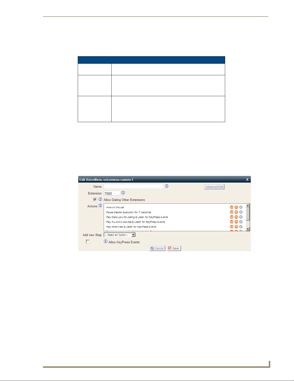
Telephone System Configuration
37
CSG SIP Communications Gateway Operation/Reference Guide
Agent Login Settings
The Agent Login Settings tab, accessible from the Manage Queues page, lets you specify the extensions for
agents to log into their queue, as well as callback login. Click Save to retain the agent login settings.
Agent Login Settings Options
Agent Login
Extension
Agent Callback
Login Extension
Agent Logout To logout of Agent Login just hang up your phone. To logout of
Use this field to specify the extension which all agents can dial to
log into the queue(s) associated with their extension.
Use this field to specify the extension which all agents can dial to
log into the queue(s) associated with their extension. This is the
same as Agent Login, but the agent does not have to remain on
the line.
Agent Callback Login, dial the same extension used to login,
specify your extension and password when prompted, and press
# when asked for your callback extension. This will successfully
log you out of all queues.
Voice Menus
A valuable feature of the CSG is the ability to create Interactive Voice Response (IVR) or voice menus. Voice
menus are designed to allow for more efficient call routing. The menus provide a caller with specific
instructions, receive responses from the caller, and process those responses into an action. Using IVR menus
for DTMF makes it easy for you to control your AMX system.
Each CSG ships with a default voice menu already created. To better understand the creation and operation of
these menus, this section examines the default menu.
FIG. 28
Default Voice Menu
Voice menus are constructed depending on your needs. Just like your business you need to create the solution
best suited to your customers. The best way to understand how a voice menu is constructed is to examine the
default “Welcome” menu provided with your CSG. Click Voice Menus - Welcome in the Voice Menus list.
The options for the welcome menu are displayed similar to the example shown in the above illustration. The
Welcome menu consists of the following steps:
Answer the Call
Wait ‘1’ Sec
Play ‘thank-you-for-calling & Listen for KeyPress
Play ‘if-u-know-ext-dial’ & Listen for KeyPress
Play ‘otherwise’ & Listen for KeyPress
Play ‘to-reach-operator’ & Listen for KeyPress
Play ‘pls-hold-while-try’ & Listen for KeyPress
WaitExten ‘6’ Sec
Page 46

Telephone System Configuration
38
CSG SIP Communications Gateway Operation/Reference Guide
In the example, when a caller dials your company number ending in 7000, the call is answered, and after a
pause of one second the caller is greeted in the following manner: “Thank you for calling. If you know your
party’s extension, please dial it now. Otherwise to reach an operator please dial 0.” If the caller tries an
extension, the menu will respond with “Please wait while I try that extension.” If no action is taken by the
caller, the menu will repeat after 6 seconds.
This is an example of a basic voice menu. In the example, each action is a step chosen from the list of available
menu options. The available menu options are as follows:
Add New Step Options
Answer This step is automatically added when creating a new menu. This step
Authenticate The Authenticate step is used to restrict access to one or more areas of your
Background This step is used to play an audio file in the background while waiting for the
Busytone The Busytone option should be selected if there is a step in the process in
Congestion The Congestion option is similar to the Busytone option. The Congestion
Digit Timeout The Digit Timeout option is used to set the maximum amount of time
DISA DISA (Direct Inward System Access) is an application which allows callers
Response
Timeout
Playback The Playback option is similar to the Background option because it will
Set Music on
Hold Class
Wait The Wait option pauses the execution of steps in the voice menu list for the
WaitExten The WaitExten option is specified to give a caller a specified amount of time
Goto Destination The Goto Destination option lets a caller choose to go to either a voice
answers the incoming call.
system. This is useful when one wants users to have to enter a PIN code to
proceed to a particular part of the current menu, to a different menu, or to
ring an extension.
caller to enter an extension or number. Playback is terminated once the user
begins to enter an extension. To select a file to play, click and hold in the
field next to the Background choice to scroll through a list of pre-recorded
sound files. In the example above, “Play ‘otherwise’ & Listen for KeyPress”
is an example of using the Background option.
which you want to play a busy signal to the caller. You would play the
busyone to the caller, for instance, if the call is over.
option should be selected if there is a step in the process in which you want
to play a congestion signal to the caller. You would play the congestion
signal to the caller, for instance, if you want to indicate the line is not
available.
allowed between key presses. If a full extension is not entered in the
specified time, the entry will be considered invalid. A field for entering the
number of seconds before timeout appears next to the option.
from outside the system to get access to an internal dial tone and place calls
from within your internal system. A passcode is required. If the passcode
entered is correct, the user is given a system dial tone on which a call may
be placed.
Note: Use caution when choosing this option. This option can pose a
security risk.
If a caller does not enter a response with the time specified in this field, the
call will terminate. This step could be put at the end of a series of menu
choices.
play a sound file you select. However, this option does not allow interruption
from a KeyPress event, and will move on to the next step in your list.
Set the group of music on hold files to be associated with this voice menu.
number of seconds you specify.
to enter an extension.
menu, a specific extension, voicemail box, or a ring group from a list of
destinations.
Page 47

Telephone System Configuration
39
CSG SIP Communications Gateway Operation/Reference Guide
Add New Step Options (Cont.)
Set Language This option gives you the ability to set the language for voice prompts in
Goto Directory The Goto Directory option sends a caller to the system phone directory.
Dial a Number via
Trunk
User Event This option gives you the ability to send an arbitrary event to the manager
Hangup The Hangup option terminates the call.
Custom App This option allows you to specify a CSG application, along with the
your voice menu. This option is especially useful if you want to begin with
the default language, and then give the option of setting a different language
for the rest of the menu. For example, voice prompts will begin in English,
but if a user is given a choice, and presses 2 for Spanish, all further voice
menu prompts will be in Spanish (provided that language module is loaded).
This gives the user the chance to select a user name from the directory if the
extension is unknown.
This option allows you to specify an external number to dial, including the
trunk that should be used for the call.
interface, with an optional body representing additional arguments. Specify
the eventname in the User Event field. If necessary, specify additional
arguments in the Body field.
application’s corresponding parameters, which is not already listed in the
Add new Step drop-down menu (e.g. ‘NoOp(hello world)’ to echo “hello
world” on the CSG CLI).
Note: The Custom App option is only visible when Advanced Options are
enabled under the Options menu item. This option should only be
configured by experienced CSG administrators.
Creating a Voice Menu
Use the following procedure as a guide to creating a voice menu.
1. On the Voi c e Me n u page, click New to create a new voice menu.
2. Specify a Name and an Extension. The extension will be the direct dial to the voice menu.
3. Specify the Steps of your voice menu using the welcome menu example and step descriptions as guides.
4. Select the Dial Other Extensions check box if you want to give a user the ability to break out of the
menu selections and dial an extension within your system.
The Dial Other Extensions option is important. This option allows an inbound caller to
break out of the listed Keypress Events and dial another extension. A malicious
person may be able to hack through your CSG implementation to find an outside dial
tone and use it for fraud. Any extensions that are known to the public should be
completely handled by the Keypress Events; callers should not be allowed to dial
other extensions. Sticking to this policy protects your CSG system from being
compromised.
5. Specify the Keypress Event actions for digits 0-9 as well as *, #, t, and i. The options available for a
Keypress Event are:
None - The associated key is not enabled.
Goto Menu - Pressing a key with this option will send the caller to a specified menu.
Goto Extension - Pressing a key with this option will send the caller to a specified extension.
Goto Queue - Pressing a key with this option will send the caller to the specified queue.
Operator - This option will send the caller to the designated operator.
Hangup - Pressing a key with this option will terminate the call.
Congestion - Pressing a key with this option will play a busy signal.
Both the t key and i key should be used for specific actions. The action associated with the t key
should be the desired action if a user response has timed-out. The action associated with the i key
should be the desired action if a user makes an invalid entry.
6. Once you have constructed your voice menu, click Save. You can then click Apply Changes to add the
voice menu to your current configuration.
Page 48

Telephone System Configuration
40
CSG SIP Communications Gateway Operation/Reference Guide
Voicemail Menu
This section lists the default voicemail menu for the CSG. You can use this menu as a guideline for
creating your own voicemail menu.
1 Read voicemail messages
2 Change folders
3 Advanced Options
0 Mailbox options
* Help
# Exit
After recording a message (incoming message, busy/unavailable greeting, or name)
While listening to a recorded voicemail message: Press # to fast forward, or * to rewind by 3 second
increments.
3 Advanced options
1 Reply
3 Envelope
5 Send Message
4 Play previous message
5 Repeat current message
6 Play next message
7 Delete current message
8 Forward message to another mailbox
1 Prepend before sending the message
2 Send without prepending
9 Save message in a folder
0 Save in new Messages
1 Save in old Messages
2 Save in Work Messages
3 Save in Family Messages
4 Save in Friends Messages
* Help; during msg playback: Rewind
# Exit; during msg playback: Skip forward
0 Switch to new Messages
1 Switch to old Messages
2 Switch to Work Messages
3 Switch to Family Messages
4 Switch to Friends Messages
# To cancel and return to main menu
5 Send Message
* Return to main menu
1 Record your unavailable message
2 Record your busy message
3 Record your name
4 Record your temporary message
1 Record your temporary message
2 Erase your temporary message (going back to the standard message)
5 Change your password
* Return to the main menu
1 - Accept
2 - Review
3 - Re-record
Page 49

Telephone System Configuration
41
CSG SIP Communications Gateway Operation/Reference Guide
Creating the Required Voice Menus for DTMF
The following procedure describes how to create IVR menus on the CSG. These menus generate DTMF
events that are consumed by the Voice & Video Communications Module to facilitate the DTMF feature.
The DTMF feature allows for remote activation of control functions defined for a NetLinx Master. If a
user calls remotely into a defined extension on the CSG, the IVR menus associated with this extension
accept touch tones which pass to the running Voice & Video Communications Module on the NetLinx
Master. The module interprets the incoming tones and processes the associated action, as applicable.
There are 14 required Voice Menus to enable complete functionality of the DTMF feature.
Required Voice Menus for DTMF
Label Function
Press 1 Generates tone for "1"
Press 2 Generates tone for "2"
Press 3 Generates tone for "3"
Press 4 Generates tone for "4"
Press 5 Generates tone for "5"
Press 6 Generates tone for "6"
Press 7 Generates tone for "7"
Press 8 Generates tone for "8"
Press 9 Generates tone for "9"
Press 0 Generates tone for "0"
Press * Generates tone for "*"
Press # Generates tone for "#"
Answer DTMF Voice menu which answers incoming
call
DTMF Voice Menu that waits for DTMF code
input
Voice Menus cannot be completely defined until all required voice menus are defined. To create the 14
required Voice Menus, perform the following steps.
1. Open a web browser, use the IP address of the CSG to navigate to the Administrative webpage of
the CSG, and login. See the Logging On to the CSG section on page 15 for more information.
2. Select Voice Menus from the left pane of the browser window.
Page 50

Telephone System Configuration
42
CSG SIP Communications Gateway Operation/Reference Guide
Steps 3 through 11 create voice menus for digits 0-9 and the * and # symbols.
3. Click Create New VoiceMenu. The Create New VoiceMenu dialog box opens (FIG. 29).
FIG. 29 Create New VoiceMenu dialog box
4. Enter Press 1 in the Name field.
5. Select User Event from the Add new Step options menu. A series of new options appear (FIG. 30).
FIG. 30 Add new Step - User Event options
6. Enter AMX in the User Event field. This field must be entered exactly as shown for the DTMF feature to
function properly.
7. Enter Press1 in the Body field. This field must be entered exactly as shown for the DTMF feature to
function properly.
8. Click the Add new Step button. The information you entered appears in the Actions area.
9. Leave the Allow Dialing Other Extension and Allow KeyPress Events check boxes unchecked.
10. Click Save.
11. Repeat Steps 3 through 10 for digits 2, 3, 4, 5, 6, 7, 8, 9, 0, *, and #, replacing "1" in the instructions with
the appropriate digit or symbol. For example, to configure #, enter Press# in the Body field. When
finished entering all remaining digits and symbols, proceed to step 12.
Steps 12 through 16 create the DTMF voice menu.
12. Click Create New VoiceMenu on the main Voice Menus screen. The Create New VoiceMenu dialog box
opens (FIG. 29).
13. Enter DTMF in the Name field.
14. Select Wai t from the Add new Step options menu. A series of new options appear (FIG. 31).
FIG. 31 Add new Step - Wait options
15. Enter 45 in the Wait field.
16. Click the Add new Step button. The information you entered appears in the Actions area.
Page 51

Telephone System Configuration
43
CSG SIP Communications Gateway Operation/Reference Guide
Steps 17 through 24 set up the KeyPress Events for each voice menu.
17. Click the Allow KeyPress Events check box.
18. Click on the "--" to the right of the "0". A drop-down menu appears (FIG. 32).
FIG. 32 Allow KeyPress Events
19. Select the VoiceMenu created above for 0, VoiceMenu -- Press0. Click Update. The drop-down menu
disappears and your selection appears in its place.
20. Repeat steps 18 - 20 for 1, 2, 3, 4, 5, 6, 7, 8, 9, *, and #.
21. Click on the "--" to the right of the "t". A drop-down menu appears.
22. Select Hangup call from the drop-down menu.
23. Click Update. The drop-down menu disappears and your selection appears in its place.
24. Click Save.
Steps 25 through 40 create the Answer DTMF voice menu.
25. Click Create New VoiceMenu on the main Voice Menus screen. The Create New VoiceMenu dialog box
opens (FIG. 29).
26. Enter Answer DTMF into the Name field.
27. Enter the extension you want to use for DTMF in the Extension field.
28. Select Answer from the Add new Step options menu.
29. Click the Add new Step button. The information you entered appears in the Actions area.
30. Select Wai t from the Add new Step options menu. A series of new options appear (FIG. 31).
31. Enter 1 in the Wait field.
32. Click the Add new Step button. The information you entered appears in the Actions area.
Steps 33 through 35 add authentication to the Answer DTMF voice menu. These steps are optional.
33. Select Authenticate from the Add new Step options menu. A series of new options appear (FIG. 33).
FIG. 33 Add new Step - Authenticate options
34. Enter the passcode you want in the Authenticate field.
35. Click the Add new Step button. The information you entered appears in the Actions area.
36. Select Goto Destination from the Add new Step options menu. A series of new options appear (FIG. 34).
FIG. 34 Add new Step - Goto Destination options
37. Select VoiceMenu -- DTMF from the To Destination options menu.
38. Click the Add new Step button. The information you entered appears in the Actions area.
39. Leave the Allow Dialing Other Extension and Allow KeyPress Events check boxes unchecked.
Page 52

Telephone System Configuration
44
CSG SIP Communications Gateway Operation/Reference Guide
40. Click Save.
Steps 41 through 46 add the DTMF destination to each voice menu.
41. On the Voice Menus screen, click the Edit button associated with "Press 0". The Edit New VoiceMenu
dialog box appears.
42. Select Goto Destination from the Add new Step options menu. A series of new options appear (FIG. 34).
43. Select VoiceMenu -- DTMF from the To Destination options menu.
44. Click the Add new Step button. The information you entered appears in the Actions area.
45. Click Save.
46. Repeat steps 41 - 45 for 1, 2, 3, 4, 5, 6, 7, 8, 9, *, and #.
Record a Voice Menu
If you want to record custom menu prompts for CSG which can be used in a voice menu, you can use the
Voice Menu Prompts tab.
FIG. 35 Custom Voice Menu Prompts Page
A list of previously recorded menus is displayed on the Custom Voice Menu Prompts page. Here, the user
may modify several options:
Custom Voice Menu Prompts Page Options
Record Again Clicking this button allows the user to make another attempt at
recording and replacing an existing custom sound file.
Play Clicking this button brings up a dialog entry box to allow the input
of an extension that the CSG will dial and play the prompt.
Delete Clicking this button will delete the selected prompt.
FIG. 36
Record Menu Prompts
Click Record a new Voice Menu Prompt to record a custom voice menu prompt. The following options will
be available:
Custom Voice Menu Prompts Page Options
File Name This text entry box specifies the saved name of the file that is to be recorded.
Format Select whether the recording will be in GSM or WAV format.
Extension Used
for Recording
Record Clicking this button causes the CSG to launch the call that will record a file.
This drop-down select box allows the user to choose which extension the CSG will
dial to wait for the user to speak the prompt.
Page 53

Telephone System Configuration
45
CSG SIP Communications Gateway Operation/Reference Guide
FIG. 37 Upload Menu Prompts
Click Upload a Voice Menu prompt to upload a custom voice menu prompt. You will be prompted to specify
the path to the audio file that you wish to upload. Each file uploaded must be less than 10 megabytes, in 8KHz
mono, and in GSM or WAV format.
Once your recording or upload of a custom voice menu prompt is finished, it will be listed on the Custom
Voice Menu Prompts page. You will be able to play back the prompt, re-record the prompt, or delete the
prompt. The prompts can now be included when creating voice menus.
Time Intervals
Time intervals are definitions of a period of time during a day, week, month, etc. which are used to route calls.
Time interval definitions are utilized in the Incoming Calling Rules section. To define a time interval, select
Time Intervals from the left menu, and then New Time Interval from the Time Intervals page.
FIG. 38 New Time Interval
Creating a Time Interval definition is fairly simple. You just need to define a range of time in which you expect
to receive calls. The following fields are used to create the definition:
New Time Interval Page Options
Time Interval
Name
By Day of Week Select this radial button if you wish to specify one or more days of any week. Select the
By Days of a
Month
Time You need to specify a time during which this interval should be applied. Select either the
Specify a unique name to help you identify this time interval when it is referred to in the
creation of calling rules. A name can be anything such as BusinessHours, OffHours, or
Holiday.
range of days using the drop-down lists. For example, if you were creating the time
interval “Business Hours” you would specify Monday in the first drop-down list and
Friday in the second drop-down list. For time intervals that occur on a single day, select
that day in both drop-down lists.
Select this radial button if you wish to specify a day of a specific month instead of a day
of a week. Enter the day of the month, and then select the month from the drop-down
list. For example, if you were creating a time interval named Christmas, you would enter
“25” and then select “December” from the drop-down list.
Entire Day checkbox, or a Start Time and End Time. In the Business Hours example,
which is from Monday to Friday, you would specify a start time of 8:00 AM and an end
time of 5:00 PM. In the “Christmas” example you would select the Entire Day checkbox.
Page 54

Telephone System Configuration
46
CSG SIP Communications Gateway Operation/Reference Guide
Click Update to save your time interval definition, or Cancel to discard your changes. Click Apply Changes
to make the new time interval active. Once a time interval definition is created, you can either Edit or Delete
the definition from the Time Interval page.
Incoming Calling Rules
Incoming Calling Rules give you the ability to use basic pattern matching to route incoming calls based on
time intervals for each analog or VoIP trunk with which you receive inbound calls. Click Incoming Calling
Rules to access the Incoming Calling Rules page.
FIG. 39 Incoming Calling Rules
The main page displays the incoming calling rules created for each trunk. No rules are displayed if you have
just setup your CSG. Click New Incoming Rule to create a new incoming calling rule. The new incoming rule
form will be displayed.
FIG. 40 Incoming Calling Rules
There are only a few options you will need to define to create a new rule.
New Time Interval Page Options
Trunk Select the trunk which the incoming rule should apply to from the
Time Interval Select the time interval from the list available in the drop-down
drop-down list. The trunk can be either an analog or VoIP trunk.
list. You may have created time intervals for business hours,
weekend hours, holiday time, etc. You can also select None if you
want to bypass any time intervals or patterns.
Page 55

Telephone System Configuration
47
CSG SIP Communications Gateway Operation/Reference Guide
New Time Interval Page Options
Pattern The Pattern field gives you the ability to use basic pattern
Destination Select the Destination for the incoming call. You can choose to
matching to differentiate calls and route them accordingly. For
instance, if a number begins with _9256, and is followed by 7 or
more digits, that would define a call within the state of Alabama. If
a call began with _9 followed by 7 digits, it would be a local call
that probably doesn’t require a long distance charge. Instead of
adding a rule for every extension or phone number you call,
specify the pattern in this rule similar to the example. All patterns
begin with the underscore “_” character. There are special
characters which can be used in patterns:
• X - Any digit from 0-9
• Z - Any digit from 1-9
• N - Any digit from 2-9
• [1,2,3,6-9] - Any digit within the brackets, in this instance 1, 2, 3,
6, 7, 8, 9.
• . - The period is the wildcard which will match anything
remaining. For example, _9011. matches anything starting with
9011.
• ! - The exclamation point is a wildcard which causes the
matching process to complete as soon as it can determine that
no other matches are possible.
Note: If you have selected an analog trunk, this field will be
grayed and populate with an s. This is not a pattern, but an
indication that the analog phone should proceed to the
destination.
send the call to to either a voice menu, a specific extension,
voicemail box, ring group, the operator, or even hang up the call.
• The Local Extension by DID destination setting allows you to
route the incoming call to a local extension based on the DID
(Direct Inward Dialing) number that is sent to you by your
telecommunications provider. Upon selecting Local Extension
by DID, you will notice the Local Extension by DID Pattern
option appear. This option gives you the ability to remove a
specified number of digits from the front of the DID number
string before routing the call to a local extension.
Note: The Local Extension by DID destination setting is not
applicable for analog trunks.
The rules you need to create are dependent on your needs. If you are configuring your system for a business,
for example, you’ll probably want to set up rules for business hours, off hours, weekend hours, etc. In any
case, you should also create a calling rule which utilizes the time interval and uses a catch all pattern to route
any calls that don’t fit the other rules you’ve created. This will insure that you don’t miss any calls.
Once you have completed the definition of each incoming calling rule, click Update. Click Apply Changes in
the upper right corner of the page to make your changes immediately available. Each rule you create will be
listed on the Incoming Calling Rules page, organized by trunk. From the main page you can either Edit or
Delete the rule.
Page 56

Telephone System Configuration
48
CSG SIP Communications Gateway Operation/Reference Guide
Voicemail
Voicemail is an option available for every extension. The relationship between the extension and voicemail is
established in Users. In that section you can specify whether voicemail is enabled for an extension, as well as
the PIN for retrieving voicemail. The Voicemail page lets you specify voicemail parameters, as well as
settings for sending voicemail notices to e-mail.
FIG. 41 Voicemail
There are three tabs on the Voicemail page used for configuration: General Settings, Email Settings, and
SMTP Settings.
General Settings
The General Settings page is the primary page used to configure CSG voicemail. Standard configuration
information is present, allowing you to confirm the extension used to check messages, as well as general
parameters such as the following:
General Voicemail Settings Options
Extention for
Checking
Messages
Direct Voicemail
Dial
Max Greeting
(seconds)
Dial "0" for
Operator
Message Options
Maximum
Message per
Folder
Maximum
Message Time
Minimum
Message Time
This option defines the extension which Users call to access their
voicemail account.
Select this checkbox to enable direct voicemail dialing. For
example, someone would be able to dial *6001 to directly dial the
voicemail box and leave a message for the person at extension
6001 if this checkbox is selected.
With this option, you specify the maximum amount of time
available to record your voicemail greeting.
Callers who are sent to voicemail can press “0” for the operator
and be transferred either during the voicemail salutation, or after
recording the message. If this option is not enabled, a caller’s
pressing “0” will be ignored.
This field sets the maximum number of messages that a user can
have in any over their voice mail box folders.
The maximum duration of a message left by a caller. Time is
specified in seconds.
The minimum duration of a message specified in seconds. Any
message left that’s under the listed duration is discarded and isn’t
processed or retrievable.
Page 57

Telephone System Configuration
49
CSG SIP Communications Gateway Operation/Reference Guide
General Voicemail Settings Options
Playback Options
Say Message
Caller-ID
Say Message
Duration
Play Envelope Turn on/off playing introductions about each message when
Allow Users to
Review
The Say Message Caller ID option reads the caller ID before the
voice mail message is played.
If this option is enabled the duration of the message, in minutes,
will be played back before the voicemail message is played.
accessing them from the voicemail application.
This option provides incoming callers the option to review their
message before it is saved and can be played back by the owner
of the voicemail extension. Standard options are presented to the
caller, allowing them to discard the message or re-record it.
E-mail Settings
The E-mail Settings page is used to set e-mail options for voicemail, as well as the format of the e-mails sent.
You must specify SMTP settings to send e-mail.
E-mail Settings Options
Send Messages
by E-mail Only
Attach
Recordings to
E-mail
Template for
E-mails
If this option is set, voicemail messages will only be accessible by
e-mail.
This option is used to choose whether voicemail is sent to a users
e-mail address as an attachment. Click the check box to enable
this option. Messages will be sent in the .wav format.
The e-mail template gives you the ability to specify the general
content for each e-mail sent with a voicemail alert. To load a
sample template, click the Load Defaults button. Be sure to
change the From address to a valid e-mail address before
saving.
SMTP Settings
The SMTP Settings page is used to enable sending voicemail alerts through e-mail.
SMTP Settings Options
SMTP Server The IP address or a hostname of an SMTP server which the CSG
can connect to, without authentication, to send voicemail
notifications to an e-mail address.
Port The port number on which the SMTP server is running. The
default port is 25.
Use SMTP
Authentication
Auth User The username used for authentication to the SMTP server.
Auth Password The password used for authentication to the SMTP server.
Click this checkbox if the SMTP server requires a username and
password for authentication.
Once you have completed specifying the settings on a tab, click Save to keep your settings, or Cancel to
discard your settings. Click Apply Changes in the upper right corner of the page to make your changes
immediately available.
Page 58

Telephone System Configuration
50
CSG SIP Communications Gateway Operation/Reference Guide
Paging/Intercom
The Paging/Intercom tab allows you to set up 1-way paging or 2-way intercom for calling an individual or a
group of extensions. This can be used to make an announcement over the speakerphone of a group of phones.
Phones which are part of a page/intercom group will not ring, but will immediately answer into speakerphone
mode. AMX recommends no more than four users in a simultaneous page/intercom group.
This functionality is dependent on a compatible and correctly configured handset. For
a user to be able to dial a page/intercom group, the ‘pagegroups’ local context must
be included in the user’s dialplan.
FIG. 42 Paging & Intercom
Click New Page/Intercom Group to define which available users will be part of a page/intercom group.
FIG. 43 New Page/Intercom Group
The following options are available when defining a new page/intercom group:
New Page/Intercom Group Options
Extension for this
Page/Intercom
Group
Type Specify the type of group for this extension.
Play a beep If this option is checked, a beep sound will be played when the intercom call is
Page/Intercom
Group Members
Available Users This is the list of users which are available to be assigned to this page/intercom group.
Specify the extension associated with this page/intercom group.
• 2-Way Intercom - The person initiating the call and all members of the intercom
group will be able to speak to each other during the call.
• 1-Way Page - Only the person initiating the call will be able to speak during the call.
All members of the paging group will be muted.
connected to inform users that they can begin talking.
This is the list of available users which are part of this page/intercom group.
Page 59

Telephone System Configuration
51
CSG SIP Communications Gateway Operation/Reference Guide
The double left arrows will move all available users to this page/intercom group. The double right arrows will
remove all page/intercom group members. The single left arrow will be move an individual available user to
the page/intercom group. The single right arrow will remove an individual page/intercom group member.
Click Save to retain your page/intercom group, or Cancel to abandon your changes. From the Paging &
Intercom page, you can either Edit or Delete a page/intercom group.
Click Page an Extension along the top to configure a key sequence which initiates a page or intercom call to a
specific extension.
FIG. 44 Settings for Paging Individual Extensions
The following settings are available:
Page an Extension Options
Prefix for Paging
an Extension
Prefix for Dialing
an Extension as
intercom
Specify the key sequence used to prefix a page call to a specific
extension. For example, setting this value to ** would allow you to
initiate a page call to extension 6000 by dialing **6000.
Specify the key sequence used to prefix an intercom call to a
specific extension, For example, setting this value to *# would
allow you to initiate an intercom call to extension 6000 by dialing
*#6000.
Click Save to retain your changes, or Cancel to abandon them.
Then click Settings along the top to specify additional settings for paging and intercom.
FIG. 45
Paging & Intercom Settings
The following setting is available:
Settings Options
Alert-Info Header This is the value that is sent in the alert info header to the phone
for an intercom call. It is not recommended that this value be
changed from the default of Intercom.
Click Save to retain your changes, or Cancel to abandon them. Once you have completed making changes to
the Paging & Intercom sections, click Apply Changes to make them immediately available.
Page 60

Telephone System Configuration
52
CSG SIP Communications Gateway Operation/Reference Guide
Conferencing
Every company reaches the point of needing more people on a phone call than it can effectively include
through three-way calling. Conference bridges allow you to include more people as well as project a
professional image. The configuration of the conference bridge and standard features is very straightforward.
Click New Conference Bridge on the Conferencing page to design a conference bridge.
FIG. 46 New Conference Bridge
The CSG Interface auto-populates the extension with the next available extension in sequence, but can be
changed to any extension number that is available. After establishing the extension for the bridge, you need to
specify the password settings for the conference. Assign the PIN Code used by participants to enter the
conference as well as the Administrator PIN Code used by the moderator of the conference to open the
conference bridge.
Now that you have established the conference bridge extension and password codes, you can set your
conference room options.
Settings Options
Marked/Admin
User Extension
Play hold music
for first caller
Enable caller
menu
Quiet Mode Do not play enter/leave sounds when callers join or leave the
Close Conference
When Last
Marked User
Exits
This option works in conjunction with the Wait for Marked User
feature. If the conference bridge is to have marked users or
admin users, those users should enter the conference from a
separate extension. Admin users can lock and unlock the
conference, and can kick the most recent conference participant.
Marked users are special users whose entrance and exit, if the
Wait for Marked User or Close Conference When Last Marked
User Exits are selected, can either begin or end the conference.
If the CEO of the company, for example, doesn’t want anyone
chatting in the conference bridge until he or she arrives, these
options are set to keep everything quiet. The main conference
extension of 6003 is configured with Wait for Marked User
selected. Everyone in the conference arriving from extension
6003 remains silent until the CEO arrives.
Checking this option makes music play for the first caller entering
a conference until another caller joins. Some people don’t like
sitting in a quiet room — even a virtual room — alone, and this
feature prevents anyone from being in that position.
This feature allows callers to access the Conference Bridge Menu
by pressing the asterisk (*) key.
conference.
When this option is selected, the conference call will be closed
when the last marked user exits the call.
Page 61
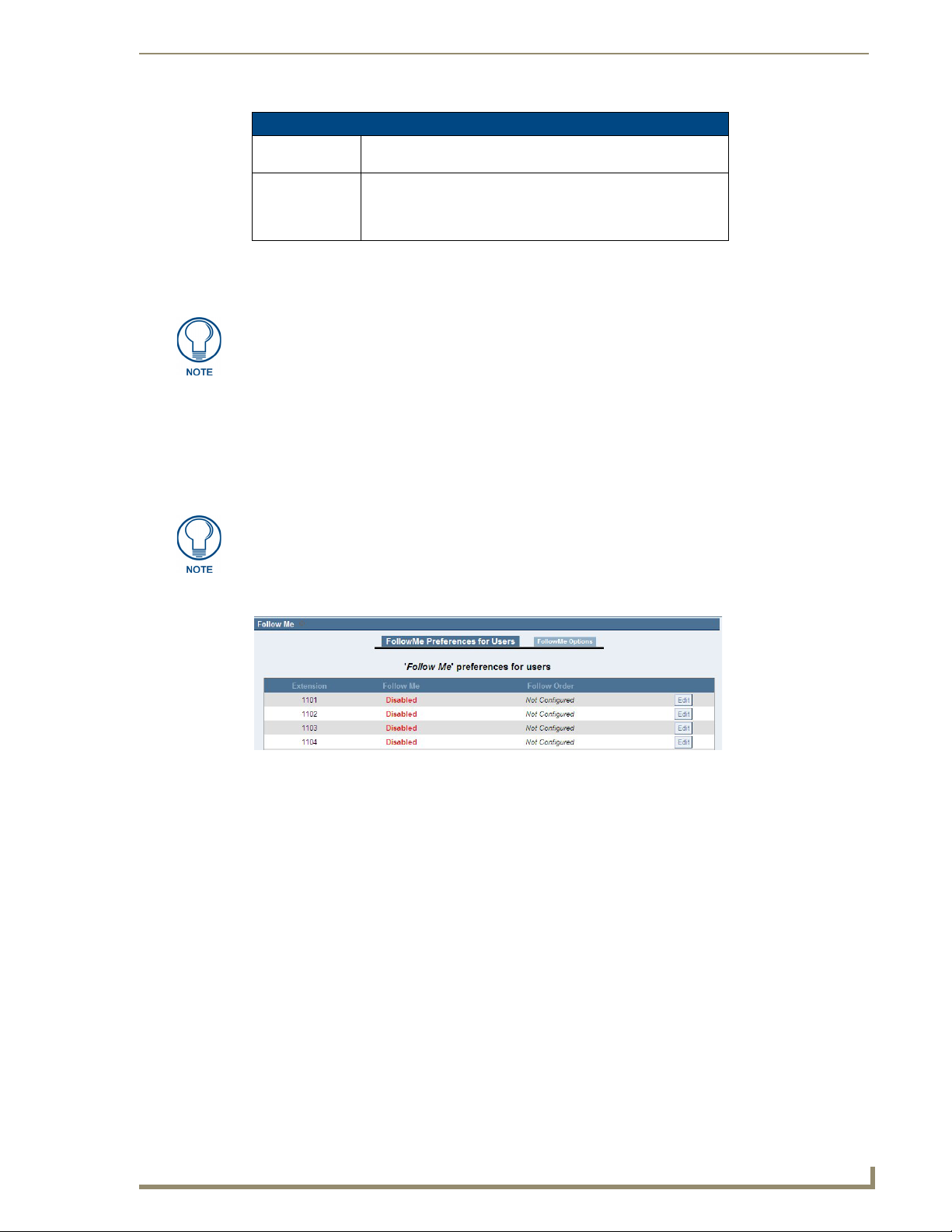
Telephone System Configuration
53
CSG SIP Communications Gateway Operation/Reference Guide
Settings Options (Cont.)
Announce callers All new callers to a conference are identified when they arrive
Wait for Marked
User
when this feature is selected.
This is a feature that keeps all participants in quiet mode until a
special participant, using a unique extension, arrives. Only after
the marked user arrives is the audio activated so that all of the
participants can speak to each other.
Click Update to retain your conference bridge definition, or Cancel to abandon your changes. From the
Conferencing page, you can either Edit or Delete a bridge definition. Once you have saved a conference
bridge definition, click Apply Changes to make the bridge immediately available.
For conference users, AMX recommends no more than 6 concurrent users in any
conference (1 each in 6 rooms, 6 users in 1 room, 2 in 3, etc). Ring group members
do not affect the concurrent call count, as the answering phone qualifies as a single
call once it's answered. The maximum number of concurrent calls with no
transcoding (such as with voicemail or conference rooms) is 12.
Follow Me
Follow Me is a feature which allows a caller to reach you wherever you may be by forwarding your calls to a
list of predefined numbers until you are reached. If you cannot be reached, Follow Me will transfer the caller
to your voicemail box. The Follow Me feature may also be referred to as Find Me.
The Follow Me feature will only function for user extensions which have voicemail
enabled.
FIG. 47 Follow Me
The following is an example scenario of using the Follow Me feature:
1. Dusty dials extension 6000 from his mobile phone to call Buddy.
2. Buddy’s office phone rings several times, but is not answered.
3. Dusty hears, “After the tone, say your name, and then press the pound key,” followed by a beep tone.
4. Dusty says his name, and then presses the pound key.
If Dusty had not said his name and/or pressed the pound key, the call would have continued on to
the next step as normal.
5. Dusty hears, “Thank you. Please hold while I try to locate the person you are calling.”
6. Then Buddy’s mobile phone and home phone begin to ring simultaneously.
7. Buddy’s android at home answers the phone and hears, "Incoming call from”. Then it hears Dusty state
his name. Then it hears, “Press 1 to accept this call, or 2 to reject it.”
This occurs while Buddy’s mobile phone continues to ring.
8. Buddy’s android quickly hangs up the phone instead of pressing 1 or 2.
If Buddy’s android had pressed 1, it would have begun speaking with Dusty, and Buddy’s mobile
phone would have stopped ringing.
Page 62

Telephone System Configuration
54
CSG SIP Communications Gateway Operation/Reference Guide
If Buddy’s android had pressed 2, the call would have been rejected, Buddy’s mobile phone would
If Buddy’s android had not hung up the phone and not pressed anything, the message would have
If the ring timeout for the Follow Me number had been met while Buddy’s android was listening to
If Buddy would have answered and accepted the call from his mobile phone while his android was
9. Buddy answers his mobile phone and hears, "Incoming call from”. Then he hears Dusty state his name.
Then he hears, “Press 1 to accept this call, or 2 to reject it.”
10. Buddy presses 1 to accept the call.
11. Lastly, Buddy begins speaking with Dusty.
If no one had answered and accepted the call, Dusty would have been transferred to
Buddy’s voicemail box.
have stopped ringing, and Dusty would have been transferred to Buddy’s voicemail box.
looped itself until either the ring timeout for the Follow Me number had been met or Buddy had
answered his mobile phone, whichever would have come first.
the accept/reject message, it would have been disconnected from the call, Buddy’s mobile phone
would have stopped ringing, and Dusty would have been transferred to Buddy’s voicemail box.
listening to the accept/reject message, it would have been disconnected from the call, and Buddy
would have begun speaking with Dusty.
FIG. 48 New Follow Me Definition
Use the following procedure as a guide to configure Follow Me for an user extension.
1. Click Edit for the user extension which you wish to configure. The edit box for the Follow Me definition
will appear.
2. To enable the Follow Me feature, select Enable for the Status option.
3. Select the ‘Music On Hold’ Class which you would like for the caller to hear while Follow Me attempts
to reach you.
4. Select the DialPlan that should be used for dialing the Follow Me numbers. The dial plan associated with
the user extension will be selected by default.
5. Click the Add Follow Me Number button toto create a list of Follow Me numbers which will be dialed
to reach the user. Upon doing so, additional options will appear near the bottom of the edit box.
6. Select Dial Local Extension if you would like to specify a local extension on the system to be dialed, or
Dial Outside Number if you would like to specify an outside number to be dialed.
To properly match one of the patterns in your Outgoing Calling Rules, be sure to
prepend the necessary digits when specyfing the outside number to be dialed.
Page 63

Telephone System Configuration
55
CSG SIP Communications Gateway Operation/Reference Guide
7. Specify the number of seconds before the ring timeout occurs for the new Follow Me number. The ring
timeout for the new Follow Me number is the total amount of time from when the Follow Me feature is
initiated to when the call is accepted.
The ring timeout is not reset or cancelled when the prompt is played to allow
someone to accept or reject the call. If the ring timeout is met while that prompt is
being played, the call will be rejected and sent to voicemail.
8. Select the Dial Order in which this Follow Me number should be dialed to reach the user.
Selecting Ring after trying previous extension/number will cause the defined Follow Me number to
be called after the last entry listed in the Destinations box.
You must select Ring after trying previous extension/number if no other Follow Me number
exists in the Destinations box. Otherwise, you will be unable to save the Follow Me definition.
Selecting Ring along with previous extension/number will cause the defined Follow Me number
to be called simultaneously along with the last entry listed in the Destinations box.
9. Click Add to add this Follow Me number to the Destinations box, or Cancel to discard it.
You may reorder the entries in the Destinations box by using the up and down arrows located to the far right
of each entry. If you wish to delete an entry, simply click the X located next to the up arrow.
Click Save to retain your changes or Cancel to discard them.
Then click FollowMe Options along the top to configure additional options for Follow Me.
FIG. 49 Follow Me Options
The following self-explanatory options can be enabled or disabled:
Playback the incoming status message prior to starting the follow-me step(s).
Record the caller’s name so it can be announced to the callee on each step.
Playback the unreachable status message if we’ve run out of steps to reach the callee, or if the
callee has elected not to be reachable.
Click Save to retain your changes or Cancel to discard them. Then click Apply Changes to make the changes
available.
Directory
The Directory settings page gives you the ability to set your preferences for the Dial by Names Directory.
Dialing the directory extension gives callers the opportunity to search the telephone directory by first or last
name.
FIG. 50 Directory Settings
Page 64

Telephone System Configuration
56
CSG SIP Communications Gateway Operation/Reference Guide
On this page you specify the extension for dialing the system directory, as well as announcement and search
preferences.
Settings Options
Directory
Extension
Also read the
extension number
Use first name
instead of last
name
Click Save to retain your changes or Cancel to discard them. Click Apply Changes to make the changes
available. To add or remove a user from the system telephone directory, edit the In Directory field of user’s
extension accessible from the Users page.
Call Features
The Call Features tab gives you the ability to configure feature codes, call parking, application maps, and dial
options. These are explained in the following sections.
Feature Codes
The Feature Codes tab gives you the ability to define a keypress sequence which will initiate a blind transfer,
attended transfer, call park, or call disconnect.
The extension to dial to access the names directory.
Select this checkbox if you would like the extension number as
well as user name to be read before presenting dialing options to
the caller.
Select this checkbox if you want to give callers the ability to
search on first name instead of last name.
Feature codes will only function when two channels are answered and bridged
together. They cannot be used while the remote party is ringing or in progress.
FIG. 51 Feature Codes
The checkbox must be selected for any feature for which you wish to define a custom key sequence. The
feature code options are described below.
Take care when specifying the key sequence for each feature code. The key
sequence detection will stop as soon as it finds a possible match (e.g. If you have the
key sequence for Blind Transfer set to ‘#’ and Attended Transfer set to ‘#2’, pressing
‘#2’ during a call will initiate a blind transfer instead of an attended transfer because
DTMF detection will stop after pressing ‘#’. An example of properly configuring two
feature codes starting with ‘#’ would be to set the key sequence for Blind Transfer to
‘#1’ and Attended Transfer to ‘#2’.)
Page 65

57
CSG SIP Communications Gateway Operation/Reference Guide
Feature Codes & Call Parking Preferences Options
Blind Transfer
Feature Code
Disconnect
Feature Code
Attended Transfer
Feature Code
Call Parking
Feature Code
Specify the key sequence to initiate the Blind Transfer feature during an
active call. The default key sequence is ‘#’. Blind Transfer may also be
referred to as an unannounced, unsupervised, or cold transfer.
When initiated, this feature will prompt you to enter the destination
extension for the blind transfer. You must then enter the destination
extension within a few seconds, otherwise the blind transfer will be
cancelled. After entering the destination extension within the alloted
time, the calling party will be transferred to the destination extension
without prior notification and the initiator of the transfer will be
disconnected. The calling party’s Caller ID will be preserved when the
call is transferred to the destination extension.
Note: The T Option and/or t Option must be enabled under Dial
Options for this to function.
Specify the key sequence to initiate the Disconnect feature during an
active call. The default key sequence is ‘*’.
When initiated, this feature will disconnect the active call.
Note: The H Option and/or h Option must be enabled under the Dial
Options tab for this to function.
Specify the key sequence to initiate the Attended Transfer feature
during an active call. A default key sequence is not defined for this
feature. Attended Transfer may also be referred to as an announced,
supervised, consult, full-consult, or warm transfer.
Initiating this feature will prompt you to enter the destination extension
for the attended transfer. You must enter the destination extension within
a few seconds, otherwise the attended transfer will be cancelled. After
entering the destination extension within the alloted time, you will hear
ringback if the destination extension is available. If the destination
extension answers, you will be given the opportunity to announce the
call transfer. Simply hang up the phone to complete the call transfer. If
you hang up before the destination extension answers, the calling party
will be transferred to the destination extension without prior notification
(i.e. similar to blind transfer, but without CallerID preservation). If the
destination extension does not answer and you do not hang up the
phone, the attended transfer will be cancelled after 15 seconds. The
calling party’s Caller ID will not be preserved when the call is transferred
to the destination extension.
Note: The T Option and/or t Option must be enabled under the Dial
Options tab for this to function.
Specify the key sequence to initiate the Call Parking feature during an
active call. A default key sequence is not defined for this feature.
Initiating this feature will prompt you with the first available parking
extension. This is the number that can be dialed to retrieve the call from
the parking lot. The caller will be immediately transferred to the specified
parking extension, and the initiator of the call park will be disconnected.
To retrieve the call, dial the parking extension that was specified by the
CSG prompt.
The amount of time that the call remains parked is determined by the
number of seconds specified in the Number of seconds a call can be
parked for field on the Call Parking tab. If the call is not retrieved within
this time, the call will be redirected to the user that originally parked the
call.
Note: The K Option and/or k Option must be enabled under the Dial
Options tab for this to function. This method of Call Parking may also be
referred to as one step parking.
Telephone System Configuration
Page 66

Telephone System Configuration
58
CSG SIP Communications Gateway Operation/Reference Guide
Call Parking
Call Parking is an CSG feature which allows a user to place a call on hold so that it can be taken off hold from
another extension. Click the Call Parking tab from the Call Features page to configure this feature. The Call
Parking page gives you the ability to define the call parking options which will enable use of this feature.
FIG. 52 Call Parking Preferences
The following options must be configured to enable call parking.
Feature Codes & Call Parking Preferences Options
Extension to Dial
to Park a Call
What Extensions
to Park Calls On
Number of
Seconds a Call
Can Be Parked
Specify the extension to call when transferring a call to hold or the
“parking lot”.
The extensions specified here will be the “parking lot”
designations for the calls you place on hold. The call on hold will
be retrieved by dialing one of these extensions.
The number of seconds a call can be placed on hold. After the
time has elapsed the call will ring the originating extension.
Parking a Call
You can park a call using either an analog or VoIP phone. To use an analog phone, hit the flash button, or
quickly press the hook switch, wait for a dial tone, then dial the extension (700). With a VoIP phone, initiate
the transfer, dial the call parking extension (e.g. 700), then complete the transfer (such as by pressing send).
The method using a VoIP phone will vary depending on the phone.
At this point, the CSG will prompt you with a number. The number it prompts you with is the number from the
pool specified. This is the number that can be entered to retrieve the call. To retrieve the call, pickup a phone,
and dial the parking number that was previously specified by the CSG prompt. The amount of time that the
call remains parked is determined by the number of seconds specified. If the call is not retrieved in this time,
the call will be redirected to the user that originally parked the call.
To properly park a call, you must use attended transfer functions. Using a blind
transfer function will not provide the parking number to the person parking the call.
This makes recovery of the call impossible, except for the fall through timeout.
Application Map
The Application Map tab gives you the ability to define a keypress sequence which will execute a specific
application, along with the application’s arguments. One example of using this feature would be to allow the
caller or callee to playback a specific sound file on demand when pressing a predefined key sequence. Click
New Application Map to define a new application map.
FIG. 53 Application Map
Page 67

Telephone System Configuration
59
CSG SIP Communications Gateway Operation/Reference Guide
The options associated with an application map are described below.
Application Map Options
Enabled Select whether or not this application map is enabled.
Feature Name Specify a unique name to be associated with this application map.
Digits Specify the key sequence used to activate this feature.
Activate On/By Select which channel of the call that the application will be
App Name Select the application to execute once the defined key sequence
Arguments Specify the arguments to be passed to the application defined in
executed on, and which channel is allowed to activate this
feature. The available settings are describe below.
• self - Run the application on the same channel that activated
this feature. This feature will be accessible by both the caller
and callee.
• peer - Run the application on the opposite channel from the one
that has activated this feature. This feature will be accessible
by both the caller and callee.
• self / caller - Run the application on the same channel that
activated this feature. This feature will be accessible by the
caller only.
• peer / caller - Run the application on the opposite channel from
the one that has activated this feature. This feature will be
accessible by the caller only.
• self / callee - Run the application on the same channel that
activated this feature. This feature will be accessible by the
callee only.
• peer / callee - Run the application on the opposite channel from
the one that has activated this feature. This feature will be
accessible by the callee only.
• self / both - Refer to the description for self.
• peer / both - Refer to the description for peer.
is detected.
Note: The application map feature is not intended to be used for
all CSG applications. Applications which are statically defined in
the extensions.conf are executed by the PBX core. In contrast,
applications which are dynamically called from an application
map are executed outside of the PBX core. It is not appropriate to
use any application which has any concept of dialplan flow when
using an application map. Examples of this would be applications
such as Macro, Goto, Background, and WaitExten.
App Name.
Enabling the application map feature will cause the CSG to remain in the media
stream during all calls. This will occur regardless of whether two endpoints are
configured to redirect their media stream from the CSG to each other after the call
setup has completed (e.g. two SIP phones with reinvite enabled).
Click Save when you are done configuring this section. Then click Apply Changes to make these changes
immediately available for new calls.
Page 68

Telephone System Configuration
60
CSG SIP Communications Gateway Operation/Reference Guide
Dial Options
The Dial Options tab gives you the ability to configure feature code permissions for the called party and the
calling party. Either party can be allowed or restricted access to the transfer, hang up, and call parking feature
codes.
FIG. 54 Dial Options
These permission options are explained below.
t Option - Allows the called party to transfer the calling party by sending the DTMF sequence
T Option - Allows the calling party to transfer the called party by sending the DTMF sequence
h Option - Allows the called party to hang up by sending the DTMF sequence defined on the
H Option - Allows the calling party to hang up by sending the DTMF sequence defined on the
k Option - Allows the called party to enable parking of the call by sending the DTMF sequence
K Option - Allows the calling party to enable parking of the call by sending the DTMF sequence
Click Save when you are done configuring this section. Then click Apply Changes to make these changes
immediately available for new calls.
defined on the Feature Codes page.
defined on the Feature Codes page.
Feature Codes page.
Feature Codes page.
defined on the Feature Codes page.
defined on the Feature Codes page.
Voicemail Groups
A voicemail group gives you the ability to create a voicemail box that can be shared by any of the users on an
CSG system. A group message can thus be sent by dialing one extension and leaving a message. Click
Voicemail Group to access the Voicemail Group page.
FIG. 55 New Voicemail Group
Page 69

Telephone System Configuration
61
CSG SIP Communications Gateway Operation/Reference Guide
Click New Voicemail Group to create a voicemail group.
New Voice Mail Group Options
Voicemail Group
Extension
Label Specify a unique name for the voicemail group which can be
User Mailboxes Click the checkbox of each user voicemail box which should be
Specify the group voicemail extension.
referred to in the configuration of your CSG.
part of the group voicemail box.
Click Save when you have completed the voicemail group definition, and then Apply Changes to make the
voicemail box immediately available. You can either Edit or Delete the voicemail group from the main
Voicemail Group page.
System Info
The general system information of the CSG is displayed from this tab, as well as tabs for your network
interfaces, disk usage, memory usage, and DHCP leases allocated on the LAN side by the CSG’s DHCP
server. If you do not have an NTP server specified, you can set your default time zone from within the General
tab. The CSG Config tab describes the exact model information. This information will be useful for technical
support.
FIG. 56
System Information
Networking
The Networking page is used to configure your general network settings, as well as your Wide Area Network
(WAN) settings, Local Area Network (LAN) settings, and Timezone settings.
FIG. 57 Networking Configuration
Page 70

Telephone System Configuration
62
CSG SIP Communications Gateway Operation/Reference Guide
The General tab, which is the default selection on the Networking page, is used to specify the following
settings:
General Tab Options
Hostname The hostname assigned to the CSG. This name will be used to
NTP Server This field gives you the ability to specify the URL or IP address of
SSH Select the SSH checkbox to activate the SSH server on the CSG.
URL for
Auto-Provisioning
The WAN tab is used to specify the settings which will enable connection to the Internet, or to an internal,
private network.
identify the CSG on your network.
an NTP server. This is useful if you wish to regularly synchronize
the CSG time setting with that of an NTP server.
The default root password is AMX. Enabling this option will cause
your unit to provide SSH access on both WAN and LAN
interfaces, which can pose a security risk.
Note: It is suggested that you change the default root password
the first time you SSH into the CSG. Use the “passwd” utility from
the shell to change the password. Changing the default password
will increase security.
The URL specified in this field is used to enable auto-provisioning
for Polycom phones. The default for this field is http://0.0.0.0/
phoneprov. The 0.0.0.0 will resolve to the IP of the CSG with the
LAN IP for requests from the LAN ports, and the WAN IP for
requests over the WAN port.
WAN Tab Options
DHCP The DHCP setting enables the automatic assignment of an IP
Enable GUI on
WAN Interface
Enable WAN Side
Provisioning
address to the CSG. This checkbox is selected by default.
Select this checkbox only if you are certain you want to enable
access to the CSG Interface via the WAN interface.
Select this option to enable the provisioning of Polycom phones
connected through the WAN.
If you have difficulty obtaining an IP address dynamically, deselect the DHCP checkbox and specify the IP
address, Subnet, Gateway, and DNS settings. This information should be available from your company
network administrator or Internet Service Provider (ISP).
The LAN tab is used to specify the settings for your local network. A local network is usually a smaller
network which is part of a WAN. The information specified here is used to access your CSG. The default IP
address specified, 192.168.69.1, is used to access the CSG Interface. You can change this address to an IP
address specified in the IP start and end ranges. In most cases, the default should be used.
The Timezone tab is used to specify the default timezone for your CSG. The time zone information is used to
set the date and time on the CSG. The time zone files are located on the flash card which comes with your
CSG. Select the appropriate timezone from the list. Click Set as Default to set the corresponding time zone as
your default time zone. Clicking the Update Timezones button will download and install the latest timezone
files from AMX’s website. You will need to restart your CSG to complete setting the time zone as your default.
To reboot your appliance, go to Options, Reboot, and click Reboot Now.
The time zone files are named after cities that adhere to the time zone you need.
Page 71

Telephone System Configuration
63
CSG SIP Communications Gateway Operation/Reference Guide
G.729 Codec
The G.729 Codec page allows you to register and manage your G.729 codec license keys. The G.729 Codec is
an industry standard algorithm that compresses and decompresses a digital audio stream. Applied to Voice
over IP (VoIP) calls, G.729 compresses the audio data to use significantly less network bandwidth than a
standard or uncompressed VoIP call. This compression allows for more calls to be carried without increasing
network capacity and allows voice to travel on limited-bandwidth connections that would otherwise not
support VoIP.
The CSG can support a maximum of 8 simultaneous calls being transcoded with
G.729. Calls using G.729 which are not being transcoded (pass-thru) do not count
towards that total.
FIG. 58 G.729 Codec Registration
Click Register a G729 License key on this Appliance to cause the CSG to download the End User License
Agreement (EULA). Read the EULA carefully. If you agree to its terms, click I agree to the above License.
FIG. 59 G.729 Codec License Information
Complete the G.729 Codec License Information form in full. The G.729 License Key field should begin with
“G729-”. Then click Register. Your registration information will be securely sent to AMX’s registration
server.
The registration process may take a few minutes to complete. A message box will appear to let you know once
the firmware has finished updating. You must reboot your CSG for these changes to take effect. Click Options
on the left menu, select the Reboot tab, and then click Reboot Now to reboot your appliance. Rebooting your
CSG will terminate any active calls.
If the registration process fails, please confirm that you have entered the G.729 license key correctly, and that
a firewall is not blocking the CSG from communicating with AMX’s registration server on TCP port 443.
If you do not currently own a G.729 codec license, click Buy new G729 Codec Licenses to be directed to a
page where you can purchase G.729 codec licenses.
Page 72

Telephone System Configuration
64
CSG SIP Communications Gateway Operation/Reference Guide
Backup
This is a housekeeping tab which allows you to back up your CSG configuration to preserve your changes. To
create a backup, click Create New Backup, specify a file name (e.g. the backup date), and select whether you
want to also backup voicemails and custom prompts. You can then download a previously created backup,
restore from the backup, delete the backup file, or upload a backup from another machine.
FIG. 60 Backup Page
Update
The Updates tab provides an interface for downloading or uploading newer CSG firmware images, and for
downloading newer Polycom firmware and bootrom images to the CSG. Visit the Tech Center at
www.amx.com to download firmware updates for the CSG.
FIG. 61 CSG Update
There are two interfaces for putting a new CSG firmware image on the CSG. The first section provides the
user the ability to specify a location from which the CSG will connect and download the updated software.
You can specify an absolute HTTP location such as: http://company.com/downloads/software.img, or the
address and filename on an accessible TFTP server. The second section provides a web-based interface for
uploading software updates. Here, you can click Browse, select a local copy of the new software, and click
Upload Image.
FIG. 62
Page 73

Telephone System Configuration
65
CSG SIP Communications Gateway Operation/Reference Guide
Click Update Polycom firmware to update the Polycom firmware or bootrom images on the CSG. A link is
provided under the Download new Firmware button to get the latest archive names. The firmware and
bootrom archive names must be specified exactly as they are at that link for the update to complete
successfully. Click Download new Firmware after you have specified the latest archive names in the
firmware and bootrom fields.
The download process may take a few minutes to complete, and even longer if your network bandwidth is
limited. A message box will appear once the firmware has finished downloading.
The Polycom firmware and bootrom images will be installed during the next reboot cycle of the CSG.
Click Options on the left menu, select the Reboot tab, and then click Reboot Now to reboot your appliance.
Rebooting your CSG will terminate any active calls.
The next reboot cycle will be increased by approximately 5 minutes during the
installation process. In addition, you must reboot your Polycom phones for them to
download the new firmware and bootrom images from the CSG.
Following an update or a restore of a backup, there may be a loss of user-created
extensions. This occurs because the settings revert back to default extension ranges
on the Options tab. If the ranges do not match the user-created extensions, they will
not be visible in the UI. Changing the User Extensions option to fit your unique range
restores the extensions to the UI. See the Options section on page 66 for more
information.
Page 74

Telephone System Configuration
66
CSG SIP Communications Gateway Operation/Reference Guide
Options
The options tab provides several options which allow you to change the password for your CSG Interface
logon, modify local extension and agent settings, as well as reboot the CSG.
FIG. 63 CSG Options
General Preferences
The General Preferences tab gives you several useful global settings for your CSG.
General Preferences Tab Options
Global Outbound
CID
Global Outbound
CID Name
Operator
Extension
Ring Timeout Specify the number of seconds to ring a device before sending a
Enable Idle
Image Display
This setting specifies the default global CallerID that is used for all
outgoing calls when no other CallerID of a higher priority is
specified.
This setting specifies the default CallerID name that is used for all
outgoing calls. You may wish to set this to your company’s name.
Leave this value blank if you want the user’s CallerID name to
appear on outbound calls.
Select the user extension from the drop-down list which will be
dialed when a user or caller presses “0” to exit voicemail. It is also
available as a Voice Menu option.
call to a user’s voicemail box or Follow Me numbers.
Select this option to enable the display of an image on a phones
LCD display when the phone is idle.
Page 75

67
CSG SIP Communications Gateway Operation/Reference Guide
General Preferences Tab Options
VoIP Phone Digit
Map
VoIP Phone Digit
Timeout
Extension
Preferences
This option gives you the ability to define a global digit mapping
string compatible with RFC 3435, section 2.1.5, to be used with
VoIP phones provisioned by this system. There is no default
setting, and this option does not sync with the dialplan assigned
to an individual user. The following examples should assist in
writing an acceptable digit mapping string.
• [2-9]11 - Calls beginning with digits 2-9, followed by digits 11,
are dialed immediately.
• 0T - Calls beginning with digit 0 are dialed after the Digit
Timeout is reached.
• +011xxx.T - Calls beginning with the + character, followed by
011 digits, and then at least three more digits before any
arbitrary number is matched, are dialed after the Digit Timeout
is reached.
• 0[2-9]xxxxxxxxx - Calls beginning with 0, followed by any digit
from 2-9, followed by 9 more digits, are dialed immediately.
• +1[2-9]xxxxxxxx - Calls beginning with the + character,
followed by 1, followed by any digit from 2-9, followed by 8
more digits, are dialed immediately.
• [2-9]xxxxxxxxx - Calls beginning with any digit from 2-9,
followed by 9 more digits, are dialed immediately.
• [2-9]xxxT - Calls beginning with any digit from 2-9, followed by
three more digits, are dialed after the Digit Timeout is reached.
These examples would be represented in this option entry box as:
[2-9]11|0T|+011xxx.T|0[2-9]xxxxxxxxx|+1[2-9]xxxxxxxx|[29]xxxxxxxxx|[2-9]xxxT
Each entry is separated by the | character. For more information,
please refer to RFC 3435.
This option specifies the number of seconds the phone will wait
after a digit is dialed before trying to establish a call when a digit
map pattern has not been matched. This must be defined as an
integer.
This section gives you the ability to define the numerical range for
all extension types.
Telephone System Configuration
Language
The Language tab gives you the ability to specify the default language for all prompts for phone to phone,
inbound, and outbound calls. If a soundpack selection is made, but the soundpack is not already installed, the
soundpack will be downloaded from the AMX website. English, Spanish, and French prompts are loaded by
default.
Change Password
The Change Password tab gives you the ability to change your administrator password.
Factory Reset
The Factory Reset tab gives you the ability to reset your CSG to the factory defaults.
If you reset your CSG to factory defaults, you will lose all configuration changes. Be
sure to make a backup of your configuration before resetting your CSG.
Page 76

Telephone System Configuration
68
CSG SIP Communications Gateway Operation/Reference Guide
Reboot
The Reboot tab gives you the ability to reboot your CSG. Some configuration changes you make may require
a system reboot.
Rebooting the appliance will terminate all active calls.
Page 77

69
CSG SIP Communications Gateway Operation/Reference Guide
Device Configuration
AMX Modero panels feature on-board Setup pages and Metreau Entry Communicators use a web
console that you can use to access device information and make various configuration changes. The
MVP-8400i, MVP-5200i, NXD-700Vi, NXD-1000Vi panels and the MET-ECOM entry communicator
support SIP calls, so you can use these models with your CSG. This chapter only covers the pages
necessary to help you configure your touch panel or entry communicator for use with the CSG. For more
information about other features on these setup pages, consult the instruction manual for your specific
device at www.amx.com.
Touch Panel Setup Pages
On the main Setup page on your touch panel, press Protected Setup (FIG. 64) to access the Protected
Setup page.
FIG. 64 Protected Setup button
Device Configuration
The Protected Setup page provides secure access to advanced panel configuration options, including
communication and security settings. Enter your password or the factory default password (1988) into
the password keypad to access this page.
The Protected Setup Navigation buttons appear on the left of the panel screen when the Protected Setup
page is active.
Other Settings Slide Out Menu
The Other Settings button (FIG. 65) provides a slide out menu with the option to select the SIP Settings
page. Select SIP to access the SIP Settings page.
FIG. 65 Other Settings slide out menu
The options on the SIP Settings page (FIG. 66) enable you to establish network settings for using your
touch panel as an IP phone. You may need to load a Duet module to enable the touch panel to receive SIP
calls. The Duet module translates between the standard interface and the device protocol. It parses the
buffer for responses from the device, sends strings to control the device, and receives commands from
the UI module or telnet sessions. Refer to the documentation supplied with the Duet Module for more
details.
A sample UI module is provided in the Voice and Video Communications Module
package. It is not intended to cover every possible application, but can be expanded
as needed by a dealer to meet the requirements of a particular installation.
Page 78

Device Configuration
70
CSG SIP Communications Gateway Operation/Reference Guide
FIG. 66 SIP Settings page
The following table describes the features on this page:
SIP Settings Options
Option Description
Back Returns you to the previous page. If you make a change on this
Connection
Status icon
Status This option enables the SIP Stack on startup. If you disable this
Connection State This option displays whether you are connected to the proxy
Proxy Address This option enables you to enter the IP address or DNS name of
page, the Back button appears dimmed and is unavailable until
you press either Save or Cancel.
The icon in the upper-right corner of each Setup page shows
online/offline state of the panel to the master.
• Bright red - disconnected
• Bright green - connected. Blinks when a blink message is
received to dark green every 5 seconds for half a second then
go back to bright green.
• Bright yellow - panel missed a blink message from the master. It
will remain yellow for 3 missed blink messages and then turn
red. It will return to green when a blink message is received.
Note: A lock appears on the icon if the panel is connected to a
secured NetLinx Master.
option, the panel will not attempt to read the rest of the
configuration and will not register with a proxy server. However,
point-to-point SIP will still be enabled allowing for existing
intercom functionality.
server.
the proxy server that you want to use to register. The IP address
depends on whether you connect the touch panel to one of the IP
Phone ports or through the LAN with the CSG.
Page 79

Device Configuration
71
CSG SIP Communications Gateway Operation/Reference Guide
SIP Settings Options (Cont.)
Option Description
Port Number The option displays UDP the port you use to connect to the proxy
server. The standard SIP port is 5060, but some providers use
different ports.
STUN Address This option enables you to enter the IP address or DNS name of
Local Domain This is the authentication domain or realm used for
User Name This option enables you to enter the user name used for
Password This option enables you to enter the password for the user at the
the Simple Traversal of UDP through NATs (STUN) server. STUN
is used for NAT tunneling of SIP messages. This field is optional.
authentication. This field is optional.
authentication to the proxy server. Normally, the user name is the
same as the phone number assigned to the extension you are
using.
proxy server.
Setting Up Your Touch Panel to Work with Your CSG
Follow these steps to configure your touch panel to work with your CSG:
1. From the main Setup page on your touch panel, press Protected Setup. The Protected Setup page
opens.
2. Press Other Settings. A slide out menu appears.
3. Press SIP. The SIP Settings page opens (FIG. 66).
4. In the Proxy Address field, enter the IP address or DNS name of the server you want to access.
5. In the Port Number field, enter the port number of the server you want to access.
6. In the User Name field, enter a user name you can use for authentication to the server.
7. In the Password field, enter the password for the user name.
8. Press Enable to have your panel read the configuration and attempt to connect to the proxy server.
9. Press Save.
10. Press Back to return to the previous page.
The firmware for your panel must be up-to-date to use SIP. Refer to your panel’s user manual for
information on upgrading its firmware.
Page 80

Device Configuration
72
CSG SIP Communications Gateway Operation/Reference Guide
Click to Login/Logout
Click to refresh Click to access the four main
the Configuration
sections of the Configuration Manager
(initial view = Summary) Manager
Click to Reboot the device
MET-ECOM Web Console
Metreau Entry Communicators have a built-in web console (FIG. 67) that allows you to easily make
various configuration settings via a web browser on any PC that has access to the device. The web
console consists of a series of web pages that separate device configuration options by category.
Collectively, the pages in the web console are referred to as the Configuration Manager. Each page of the
Configuration Manager is described in the following sub-sections.
FIG. 67 Configuration Manager - Summary of Settings Page (initial view)
Page 81

Device Configuration
73
CSG SIP Communications Gateway Operation/Reference Guide
Configuration Page - SIP Settings Tab
The options on the SIP Settings tab of the Configuration page are used to set the proxy server address
and port and the username and password to log into the server. These settings enable VoIP and enable
you to give your Metreau Entry Communicator phone capabilities to contact other units, such as
intercom-enabled touch panels and IP phones.
FIG. 68 Configuration page - SIP Settings tab
Configuration Page - SIP Settings Tab
Username This option enables you to enter the user name used for authentication to the proxy
server. Normally, the user name is the same as the extension you are using.
Password This option enables you to enter the password for the user at the proxy server.
Server Address This option enables you to enter the IP address or DNS name of the proxy server that
you want to use to register. The IP address depends on whether you connect the entry
communicator to one of the IP Phone ports or through the LAN with the CSG.
Server Port The option displays UDP the port you use to connect to the proxy server. The standard
SIP port is 5060, but some providers use different ports.
STUN Address This option enables you to enter the IP address or DNS name of the Simple Traversal of
UDP through NATs (STUN) server. This field is optional.
Local Domain This is the realm used for authentication. This field is optional.
Enable Phone This option enables the SIP Stack on startup. If you disable this option, the Metreau
Entry Communicator will not attempt to read the rest of the configuration and will not
register with a proxy server. However, point-to-point SIP will still be enabled allowing for
existing intercom functionality
Connection Displays whether your connection to the proxy server is registered. This field is
view-only.
Page 82

Device Configuration
74
CSG SIP Communications Gateway Operation/Reference Guide
Configuring VoIP
On the Configuration page, select the SIP Settings tab.
1.
2. In the Username field, enter the user name used for authentication to the proxy server.
3. In the Password field, enter the password for the user name.
4. In the Server Address field, enter the IP address or DNS name of the proxy server you want to use to
register.
5. In the Server Port field, enter the port of the proxy server.
6. In the STUN Address field, enter the IP address or DNS name of the STUN server. This step is
optional.
7. In the Local Domain field, enter the realm used for authentication. This step is optional.
8. Click the Enable option button to activate the SIP settings.
9. Click Accept.
You can load a Duet module to enable the entry communicator to utilize SIP to
contact other units and touch panels. The Duet module translates between the
standard interface and the device protocol. It parses the buffer for responses from the
device, sends strings to control the device, and receives commands from the UI
module or telnet sessions. Refer to the documentation supplied with the Duet Module
and the Communications Module User Guide (available at www.amx.com) for more
details.
Installing the NetLinx Module
Each panel has an available module which may be helpful with getting the panel to work with the CSG.
Download the module for the intercom panel from the Tech Center at www.amx.com. Unzip the file, and
include it in your NetLinx project file. For information on using the NetLinx Module, consult the
Communications Module User Guide available at www.amx.com.
Page 83

Device Configuration
75
CSG SIP Communications Gateway Operation/Reference Guide
Page 84

It’s Your World - Take Control™
3000 RESEARCH DRIVE, RICHARDSON, TX 75082 USA • 800.222.0193 • 469.624.8000 • 469-624-7153 fax • 800.932.6993 technical support • www.amx.com
2011 AMX. All rights reserved. AMX and the AMX logo are registered trademarks of AMX. AMX reserves the right to alter specifications without notice at any time.
©
8/11
 Loading...