

Page 1
instruction manual
CP4/A - 4" Color Touch
Panels with Audio
(Firmware version G3)
To u c h Panels and Accessories
Page 2

AMX Limited Warranty and Disclaimer
AMX Corporation warrants its products to be free of defects in material and workmanship under normal use for three
(3) years from the date of purchase from AMX Corporation, with the following exceptions:
• Electroluminescent and LCD Control Panels are warranted for three (3) years, except for the display and touch
overlay components that are warranted for a period of one (1) year.
• Disk drive mechanisms, pan/tilt heads, power supplies, and MX Series products are warranted for a period of one
(1) year.
• AMX Lighting products are guaranteed to switch on and off any load that is properly connected to our lighting
products, as long as the AMX Lighting products are under warranty. AMX Corporation does guarantee the
control of dimmable loads that are properly connected to our lighting products. The dimming performance or
quality cannot be guaranteed due to the random combinations of dimmers, lamps and ballasts or transformers.
• Unless otherwise specified, OEM and custom products are warranted for a period of one (1) year.
• AMX Software is warranted for a period of ninety (90) days.
• Batteries and incandescent lamps are not covered under the warranty.
This warranty extends only to products purchased directly from AMX Corporation or an Authorized AMX Dealer.
All products returned to AMX require a Return Material Authorization (RMA) number. The RMA number is
obtained from the AMX RMA Department. The RMA number must be clearly marked on the outside of each box.
The RMA is valid for a 30-day period. After the 30-day period the RMA will be cancelled. Any shipments received
not consistent with the RMA, or after the RMA is cancelled, will be refused. AMX is not responsible for products
returned without a valid RMA number.
AMX Corporation is not liable for any damages caused by its products or for the failure of its products to perform.
This includes any lost profits, lost savings, incidental damages, or consequential damages. AMX Corporation is not
liable for any claim made by a third party or by an AMX Dealer for a third party.
This limitation of liability applies whether damages are sought, or a claim is made, under this warranty or as a tort
claim (including negligence and strict product liability), a contract claim, or any other claim. This limitation of
liability cannot be waived or amended by any person. This limitation of liability will be effective even if AMX
Corporation or an authorized representative of AMX Corporation has been advised of the possibility of any such
damages. This limitation of liability, however, will not apply to claims for personal injury.
Some states do not allow a limitation of how long an implied warranty last. Some states do not allow the limitation or
exclusion of incidental or consequential damages for consumer products. In such states, the limitation or exclusion of
the Limited Warranty may not apply. This Limited Warranty gives the owner specific legal rights. The owner may
also have other rights that vary from state to state. The owner is advised to consult applicable state laws for full
determination of rights.
EXCEPT AS EXPRESSLY SET FORTH IN THIS WARRANTY, AMX CORPORATION MAKES NO
OTHER WARRANTIES, EXPRESSED OR IMPLIED, INCLUDING ANY IMPLIED WARRANTIES OF
MERCHANTABILITY OR FITNESS FOR A PARTICULAR PURPOSE. AMX CORPORATION
EXPRESSLY DISCLAIMS ALL WARRANTIES NOT STATED IN THIS LIMITED WARRANTY. ANY
IMPLIED WARRANTIES THAT MAY BE IMPOSED BY LAW ARE LIMITED TO THE TERMS OF THIS
LIMITED WARRANTY.
Page 3

Table of Contents
Table of Contents
Product Information .................................................................................................1
Specifications ................................................................................................................ 1
Cleaning the Touch Overlay.............................................................................................. 5
AC-CP4A/WRB Water-Resistant Faceplate for AXD-CP4/A............................................. 5
Specifications ....................................................................................................................... 6
Installation .................................................................................................................7
Mounting the AXD Wall Mount Panels .............................................................................. 7
Wall Mount installation using a pre-wall CB-CP4/A Conduit Box............................................. 7
Wall Mount panel installation into Drywall using Expansion Clips ......................................... 10
Wall Mount panel installation onto a flat surface using solid-surface screws......................... 13
Installation of the AC-CP4A/WRB Faceplates................................................................. 16
Drywall Surface upgrade installation ...................................................................................... 17
Solid Surface upgrade installation.......................................................................................... 18
Removing the AXT Faceplate/Bezel ............................................................................... 19
Removing and replacing AXT pushbuttons............................................................................ 20
Wiring the Touch Panel ................................................................................................... 21
Wiring guidelines.................................................................................................................... 21
Wiring the CP4/A terminal connectors and cables................................................................. 22
Additional CP4/A wiring configurations .................................................................................. 23
Using the CP4/A Programming Jacks ............................................................................. 25
Designing Touch Panel Pages ..............................................................................27
Buttons ............................................................................................................................ 27
Activating Edit Mode........................................................................................................ 28
Setting the Device Base .................................................................................................. 29
Setting the Device Used.................................................................................................. 30
Adding a Page................................................................................................................. 30
Setting the page color ............................................................................................................ 30
Adding a Button............................................................................................................... 30
Resizing a button ................................................................................................................... 31
Defining On-Screen Button Properties............................................................................ 31
Setting the channel code........................................................................................................ 31
Setting the variable text code................................................................................................. 32
Setting the page flip ............................................................................................................... 32
Setting the button colors for channel-off conditions ............................................................... 32
Adding text, icons, and bitmaps to a button ........................................................................... 33
4" Color Touch Panels with Audio
i
Page 4

Table of Contents
Creating a Bargraph and Joystick................................................................................... 33
Adding a bargraph or joystick button...................................................................................... 33
Setting Bargraph and Joystick Properties....................................................................... 33
Setting the level code............................................................................................................. 34
Using the Adjust Sensors Setup Page ............................................................................ 34
Using the Audio and IR Device Setup page.................................................................... 37
External PushButtons...................................................................................................... 38
Setting the pushbutton LED illumination ................................................................................ 38
Light Sensor .................................................................................................................... 39
Passive Infrared Sensor.................................................................................................. 39
IR Receiver ..................................................................................................................... 39
Audio Tones .................................................................................................................... 39
Speaker Volume.............................................................................................................. 39
Microphone ..................................................................................................................... 39
Using TPDesign3 to Download Bitmaps, Icons, and Fonts............................................. 40
Programming ..........................................................................................................41
Serial Commands............................................................................................................ 41
System Send_Commands .............................................................................................. 43
Programming Numbers ................................................................................................... 52
Shorthand Send Commands........................................................................................... 53
Color Send_Commands.................................................................................................. 58
Variable Text Send_Commands ..................................................................................... 60
Shorthand Variable Text Commands .............................................................................. 62
Button String Commands................................................................................................ 65
Upgrading the Firmware ........................................................................................67
Communication Methods for CP4/A Firmware Update ................................................... 67
Upgrading the Firmware Using NetLinx Studio ............................................................... 69
Upgrading Firmware through a COM port.............................................................................. 69
Upgrading the Firmware through an IP Address.................................................................... 71
Upgrading the Firmware Using SOFTROM .................................................................... 73
Configuration.......................................................................................................................... 73
Downloading the Firmware .................................................................................................... 74
Replacing the Battery ............................................................................................75
AXT-CP4/A Battery Replacement ................................................................................... 75
AXD-CP4/A Battery Replacement................................................................................... 77
ii
4" Color Touch Panels with Audio
Page 5
Product Information
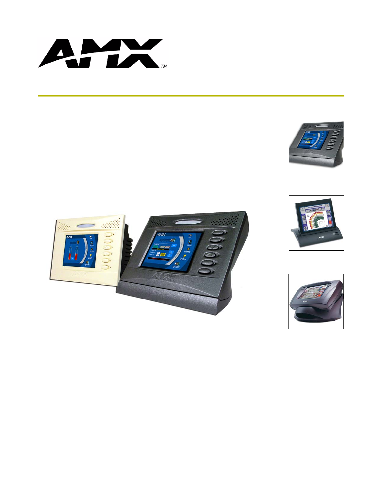
The Color Passive-Matrix Audio Mini-Touch Panels (AXD-CP4/A and AXT-CP4/A) contain a
4-inch 256-color passive-matrix liquid crystal display (LCD). These panels are equipped with an
infrared motion sensor, light sensor, IR receiver, internal audio speakers, internal microphone,
external LED buttons, and removable buttons. Using the TPDesign3 Touch Panel Design program,
you can create custom pages with buttons, icons, sliders, bargraphs, time displays, logos, and
drawings.
The AXD-CP4/A is designed for wall mounting with a Wall Mount faceplate. The AXD unit also
uses an optional CB-CP4/A conduit/wall box for "pre-wall" surfaces.
The AXD-CP4/A panels come inserted within a plastic backbox (mountable into most
surfaces) that should not be confused with the optional metal CB-CP4/A conduit box
(metallic optional component).
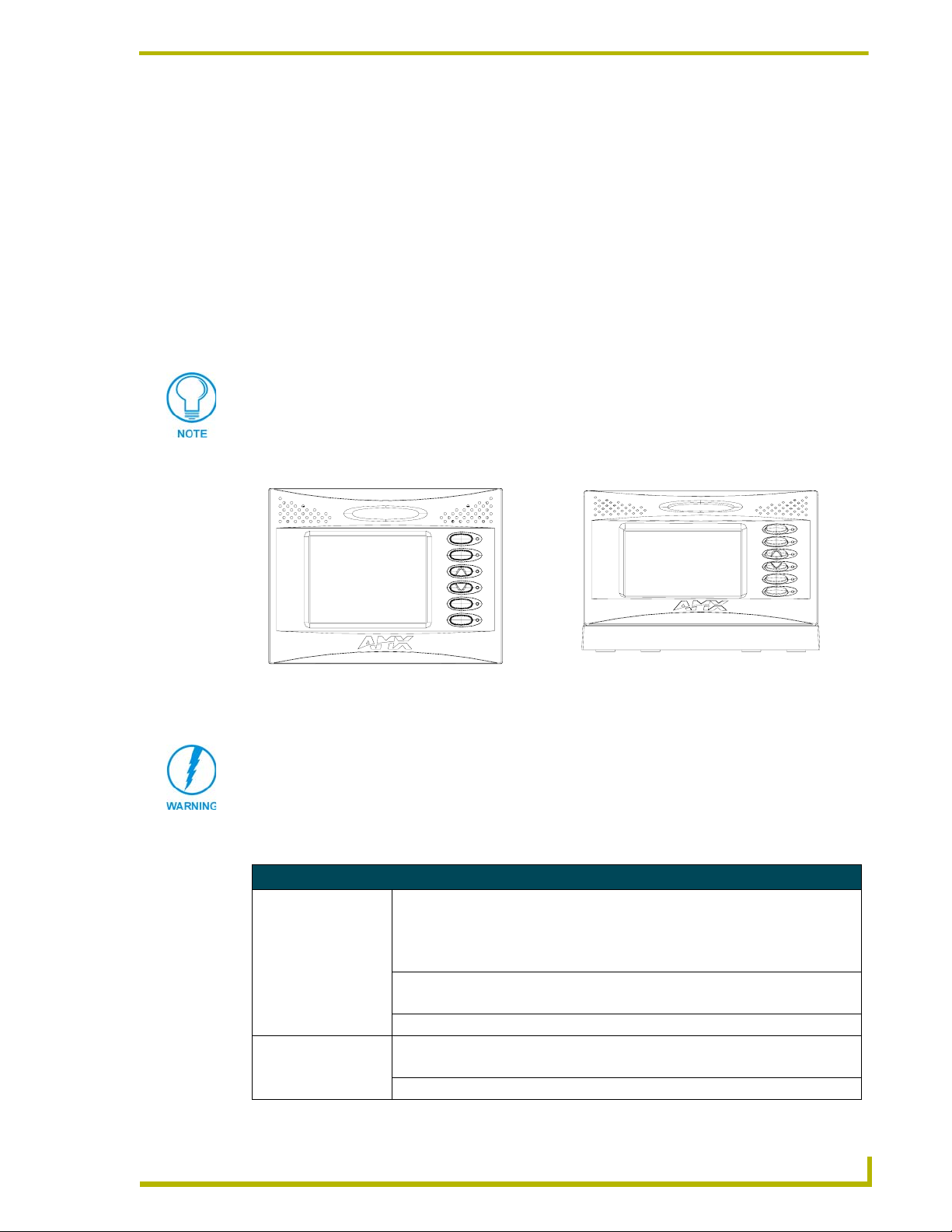
FIG. 1 shows the AXD-CP4/A and AXT-CP4/A panels.
Product Information
AXD-CP4/A (Front view)
FIG. 1 Sample AXD-CP4/A and AXT-CP4/A
Verify the TPDesign3 program being used is Version 3.16 build 193 or higher.
The Updated EXE for TPDesign3 can be found at AMX.com > Tech Center >
Downloadable Files > Application FIles > TPDesign3. Earlier versions of TPD3
will not correctly function with these panels.
AXT-CP4/A (Front view)
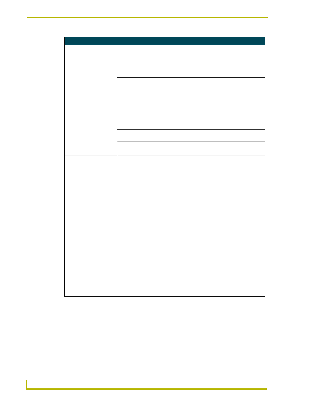
Specifications
Specifications
Dimensions (HWD):
AXD-CP4/A • Housing: 4.60" x 5.34" x 1.87" (11.68 cm x 13.56 cm x 4.75 cm)
• Faceplate: 4.60" x 6.13" x 0.35" (11.68 cm x 15.57 cm x 0.89 cm)
• CB-CP4/A Conduit/wallbox: 4.09" x 5.51" x 3.40" (10.39 cm x 13.99 cm x 8.64 cm)
AXT-CP4/A • Tabletop unit: 4.22" x 6.24" x 4.99" (10.72 cm x 15.85 mm x 12.67 mm)
• Faceplate: 4.60" x 6.13" x 0.35" (11.68 cm x 15.57 cm x 0.89 cm)
CB-CP4/A • Conduit/wallbox: 3.92" x 5.51" x 3.40" (9.96 cm x 13.99 cm x 8.64 cm)
Weight:
AXD-CP4/A 2.23 lbs. (1.02 kg)
AXT-CP4/A 2.26 lbs. (1.03 kg)
4" Color Touch Panels with Audio
1
Page 6
Product Information
Specifications (Cont.)
Enclosures:
AXD-CP4/A
(FG5921-23)
AXT-CP4/A • Table Top enclosure is available in either Dark Grey (FG5921-30) or Platinum
Power Requirements: • Constant current draw: 770 mA @ 12 VDC
Minimum power supply
required:
Memory
(factory default):
• BackBox with black matte finish
• Detachable front panel bezel are available in White (default), Black, and Beige
(FG5921-31)
• Startup current draw: 1.2 A @ 12 VDC
• PSN2.8 Power Supply (FG423-17)
- Includes U.S. power cord, with a 5mm captive-wire connector
• 512 KB of SRAM and 2 MB of Flash for a total memory of 2.5 MB.
The following is a detailed explanation of the on-board memory parameters:
• Graphics Buffer Memory:
- SGRAM
- 1 Mbit x 32 ==> 4 MByte
- Non-user accessible
- Volatile
• Flash Memory:
- CMOS Flash
- 16 MBit x 8 ==> 2 MByte
- Partially user accessible
- Non-volatile
Note: ~400 kByte is used by the firmware and is accessible only to the
firmware during both normal operation and firmware downloads.
Note: ~1600 kByte is used by the user program and is used by TPD3
designs for bitmaps, icons, and fonts. This can be cleared using either the
external "ZAP!" command or the on-panel Factory Reset button.
• RAM:
- SRAM
- 256 kByte x 16 ==> 512 kByte
- Partially user accessible
- Non-volatile via the battery backup (volatile when batteries are removed)
Note: 256 kByte is used by firmware and is accessible only to the firmware
during normal operation.
Note: 256 kByte is used by the user program and is used by TPD3 designs
for buttons, pages, and everything else not listed in the above Flash
parameter. This can be cleared using the external "ZAP!" command or
on-panel Factory Reset button.
• Clock Chip:
- RAM
- 31 Byte
- Non-user accessible
- Non-volatile via the battery backup (volatile when batteries removed)
- 31 bytes are used by the firmware to store AMX configuration information.
Note: If the battery is removed to clear the memory, it wipes out the AMX
configuration information.
•EPLD:
- EEPROM
- 32 Macrocells
- Non-user accessible
- Non-volatile
- Used by hardware for board logic (unable to clear or update)
2
4" Color Touch Panels with Audio
Page 7
Product Information
Specifications (Cont.)
Panel LCD Parameters: • Contrast ratio: 17:1
• Display area: 3.8 inches (9.65 cm)
• Screen resolution (HV): 320 x 240 pixels
• Viewing angles (100° total viewing angle):
Horizontal: +
Ver tic a l : +
IR Reception Angle: • 45° up on the AXT (30° on the AXD) from the horizontal plane
• 15° down on the AXT (30° on the AXD) from the horizontal plane
• 40° right of the vertical plane (both AXD and AXT units)
• 40° left of the vertical plane (both AXD and AXT units)
IR Reception Range: • Maximum range - 15 feet (4.57 m) for the AXT and 22 feet (6.71 m) for the AXD
Front Panel Components:
External Buttons: • 6 inter-changeable external pushbuttons. Pushbutton assignments can include
the typical Device/Channel numbers, Flip to Page option, and String/Macro.
• Buttons are used as interface tools that operate on-screen menus or turn On/
Off the controlled equipment.
• Both AXD and AXT panels come shipped with 6 blank buttons.
External LEDs: • 6 LEDs are located alongside each external pushbutton.
• Independently operated and programmed
• Used as status indicators. Along with the buttons, these can have the following
feedback types assigned to them in TPDesign3 - Channel, Inverted Channel,
Always On, Momentary, Channel Feedback, Inverted Channel, and Blink.
• They can then be used in many of the same ways as any other on-screen
button.
Button Caps: • Set of 18 changeable button caps consisting of: 6 blanks, 2 embossed with
Up/Down arrows, and 10 pad-printed labels. These buttons match the bezel
coloring.
• Custom engraved buttons are available through your AMX sales representative
• AXD buttons: Black set (60-5921-41BK), Beige set (60-5921-41BG), and
White set (60-5921-41WH)
• AXT buttons: Dark Grey set (60-5921-37) and Platinum set (60-5921-38)
Button Labels: • 10 pad-printed labels
• These buttons contain 10 symbols covering the following functions: MENU,
LIGHTS, AUDIO, VIDEO, ENVIRONMENT, SECURITY, INTERCOM, MUTE,
DRAPES, and POWER
• Refer to the Mounting the AXD Wall Mount Panels - FIG. 10 on page 13 for
more information.
Light Detector: • Photosensitive light detector for adjustment of the panel brightness.
Motion Sensor (PIR): • Proximity Infrared Detector to wake the panel when the panel is approached.
• Activation range: +
center.
IR Receiver: • 38 KHz, one-way IR reception (for AMX codes only)
Microphone: • Used for audio conferencing applications (intercom functionality)
50° (left and right from center)
50° (up and down from center)
20° vertically from center and + 45° horizontally from
4" Color Touch Panels with Audio
3
Page 8
Product Information
Specifications (Cont.)
Front Panel Components
(Cont.):
Speakers: • Frequency response 450 Hz - 7 KHz
• 8 ohm
• 1 watt
Audio Levels: • Microphone output:
Line level audio
Differential drive
Programmable gain from 7dB to 50db in 31 steps of 1.5 db (linear taper)
• Audio input:
Line level audio
Differential drive
Programmable gain from -26dB to +34 dB in 31 steps of 2dB each.
Rear Connectors:
AXlink/PWR: • 4-pin 3.5 mm mini-Phoenix connector for communication to the AMX Central
Controller providing both data and power
Audio: • 8-pin 3.5 mm mini-Phoenix connector for audio input/output
Programming Port: • 2.5 mm stereo conductor jack (side mounted)
Compatibility: • Axcess, NetLinx, and Landmark systems
Character Support: • Unicode
• Characters for middle-eastern languages such as Arabic are not supported
Operating / Storage
Environment:
Included Accessories: • Installation Kit for AXD panels (KA5921-02)
• Indoor Operating Temperature: 10° C (50° F) to 40° C (104° F)
• Indoor Operating Humidity: 5% to 90% RH (non-condensing)
• Installation Kit for AXT panels:
®
character support for far-eastern languages such as Chinese.
within the Unicode fonts because they are bi-directional. Buttons with Unicode
fonts can only be created and edited using TPDesign3.
- 2.5 mm stereo conductor programming cable (FG10-817)
- 4-pin 3.5 mm mini-Phoenix data/power connector (41-5047)
- 8-pin 3.5 mm mini-Phoenix audio connector (41-5083)
- Drywall clip set:
2 -drywall clamps and 2- #6 (2" long) screws (62-5924-05)
- 6 included blank buttons (pre-mounted into the AXD chassis)
- One bag containing 12 custom buttons (2 embossed/10 pad-printed)
(65-6004)
- Set of three Detachable Faceplates with corresponding buttons:
- White faceplate (60-5921-40WH) and White button set (60-5921-41WH)
- Black faceplate (60-5921-40BK) and Black button set (60-5921-41BK)
- Beige faceplate (60-5921-40BG) and Beige button set (60-5921-41BG)
- 2.5 mm stereo conductor programming cable (FG10-817)
- 6 included blank buttons (pre-mounted into the AXT chassis)
- 10’ (3.05 m) custom Table Top cable (CA5921-01)
- One bag containing 12 custom buttons (2 embossed/10 pad-printed)
4
4" Color Touch Panels with Audio
Page 9
Product Information
Specifications (Cont.)
Optional Accessories: • AC-CP4A/WRB, Water resistant bezel set for AXD-CP4/A (beige, black, white)
(FG5921-24)
• Axcess programming cable (DB9 to DB9) (FG10-727)
• CB-CP4/A (FG033-10) Conduit/wallbox (includes drywall clips and screws for
installation to studs during the construction phase).
- Conduit/Wallbox should only be mounted to a beam before a drywall is
installed (pre-wall).
• PSN2.8 Power Supply (12 VDC) (FG423-17)
• PSN6.5 Power Supply (12 VDC) (FG423-41)
(recommended for use on the CP4/A)
Cleaning the Touch Overlay
You should clean the touch screen overlay often. Always use clean cotton cloths, and a spray bottle
of cleaning solution consisting of 50% isopropyl alcohol and 50% water.
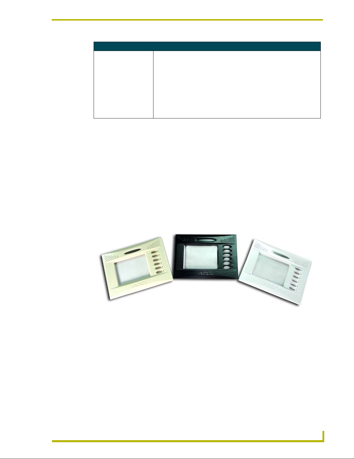
AC-CP4A/WRB Water-Resistant Faceplate for AXD-CP4/A
AMX now offers a new option - a set of water-resistant bezels for AXD-CP4/A touch panels:
AC-CP4A/WRB (FIG. 2). The faceplate set includes all three (3) color configurations - beige,
black, and white - covered with a thin transparent water-resistant film that covers the entire surface
of the bezel including the touch screen, sensor lens, and pushbuttons. It also includes a rubber-foam
gasket to "seal" the gap between the bezel, the back box and the wall. It is a perfect solution that
brings the power of AMX touch panels into wet and splashy environments inside your house or
office building.
FIG. 2 Sample AXD-CP4/A and AXT-CP4/A
4" Color Touch Panels with Audio
AC-CP4A/WRB faceplates (Beige, Black, and White)
FG5921-24
5
Page 10
Product Information
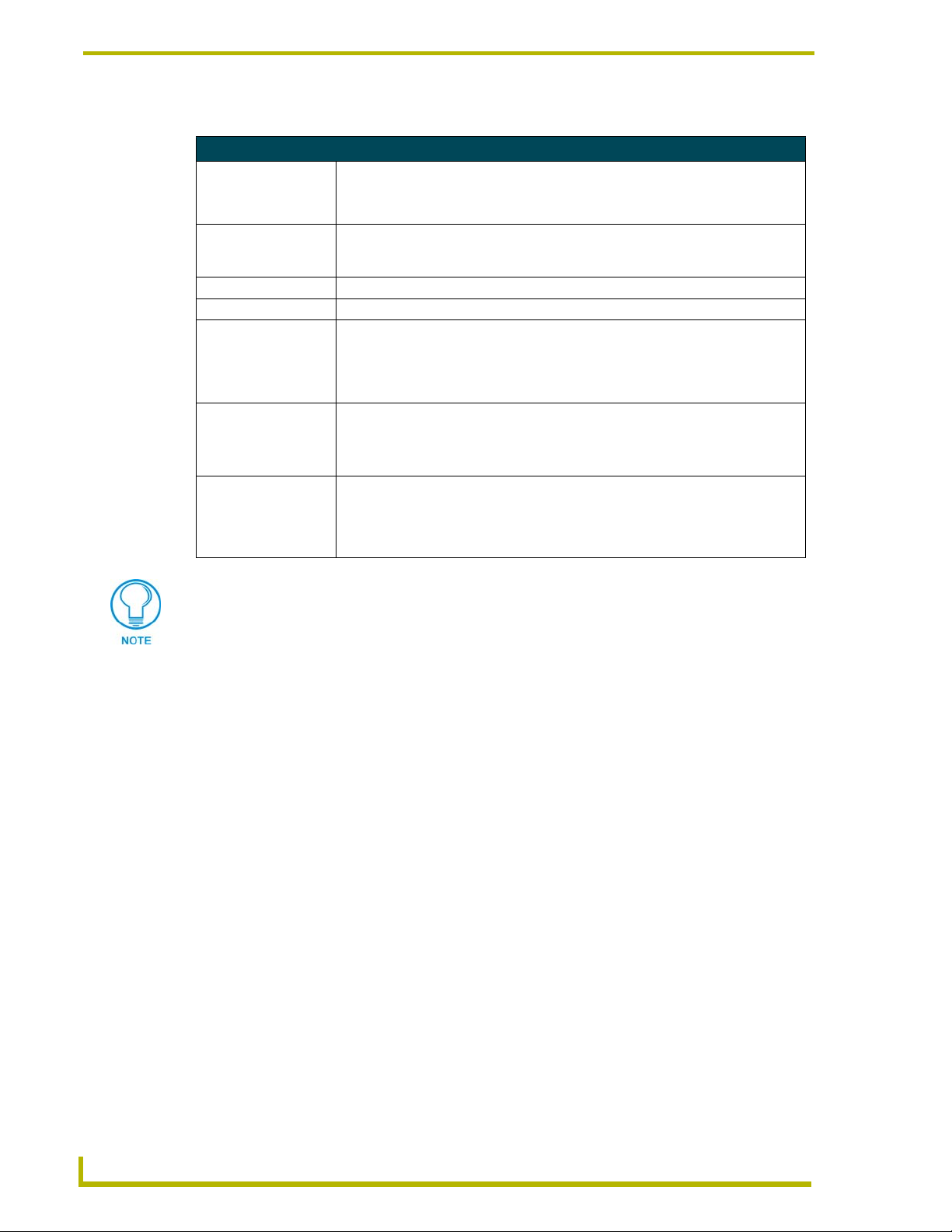
Specifications
Specifications (Cont.)
Dimensions (HWD):
AC-CP4A/WRB
Foam Insulation
Description: • Water- resistant faceplate for existing AXD-CP4/A touch panels. This faceplate
Compatibility: • All AXD-CP4/A (Wall Mount) Touch Panels
Weight: • 75 grams
Features: • Faceplate mounts to any existing AXD-CP4/A.
Included
Accessories:
Operating /Storage
Environments:
• 4.59" x 6.13" x 0.35" (11.66 cm x 15.57 cm x 1.27 cm)
• Thickness: 0.125" (3.12 mm)
covers the LCD and buttons. The included foam insulation is placed around and
behind the edges of the AXD housing (along the screw locations).
• Provides three different faceplate colors (Beige/Black/White).
• Foam insulation protects the internal circuitry from moisture and the elements.
• Insulator cutouts fit perfectly around existing housing screws.
• Three (3) faceplates: Beige (60-5921-44BG), Black (60-5921-44BK), and White
(60-5921-44WH)
• One strip of foam insulation (with screw cutouts) that mounts around the inside
border of the AXD housing
• Operating Temperature: 10° C (50° F) to 40° C (104° F)
• Operating Humidity: 20 - 100% RH
• Storage Temperature: -20° C (-4° F) to 60° C (140° F)
• Storage Humidity: 5 - 85% RH
NOTE: The AC-CP4A/WRB is intended for installation to AXD units.
The two main installation environments where this accessory can be used are: Solid
surface (using four #4-40 solid surface screws) and Drywall surface
(using 2 - #6 drywall clips and screws).
6
4" Color Touch Panels with Audio
Page 11
Installation
Mounting the AXD Wall Mount Panels
The following paragraphs describe mounting the touch panel directly into a drywall, solid surface,
and into a Conduit Box. Wall Mount panels (AXDs) are contained within a plastic back box. This
back box is not removed in either the Conduit Box (CB-CP4/A) or solid surface installation
methods.
The CP4/A has a 4-pin mini-Phoenix AXlink connector (for data and power) and 8-pin
mini-Phoenix Audio connector (for audio/microphone communication) locations on the rear of the
unit. The AXT-CP4/A comes shipped with a pre-wired tabletop cable (CA5921-01). Manual wiring
of the connector ports is recommended for any AXD or custom installations.
The AXD and AXT CP4/A touch panels have different IR reception angle
specifications based on either their location, elevation, and/or distance from the IR
transmission source.
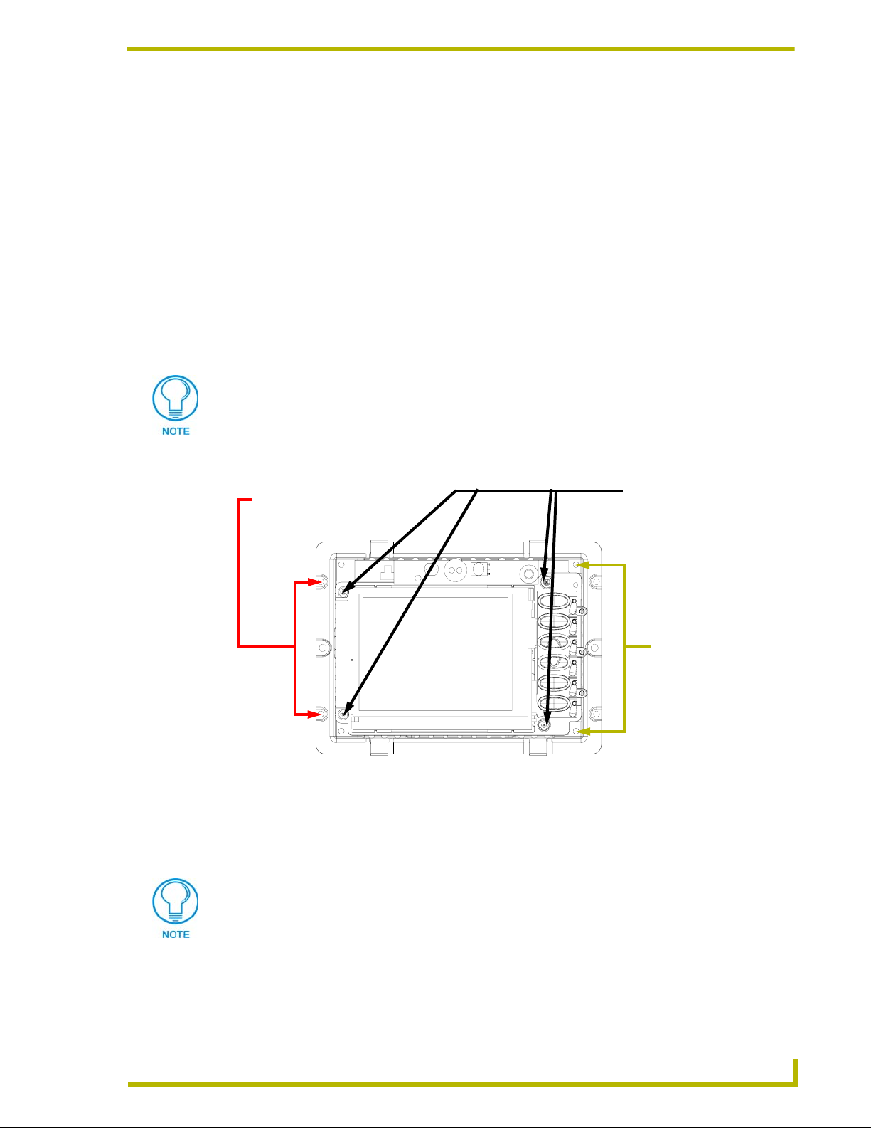
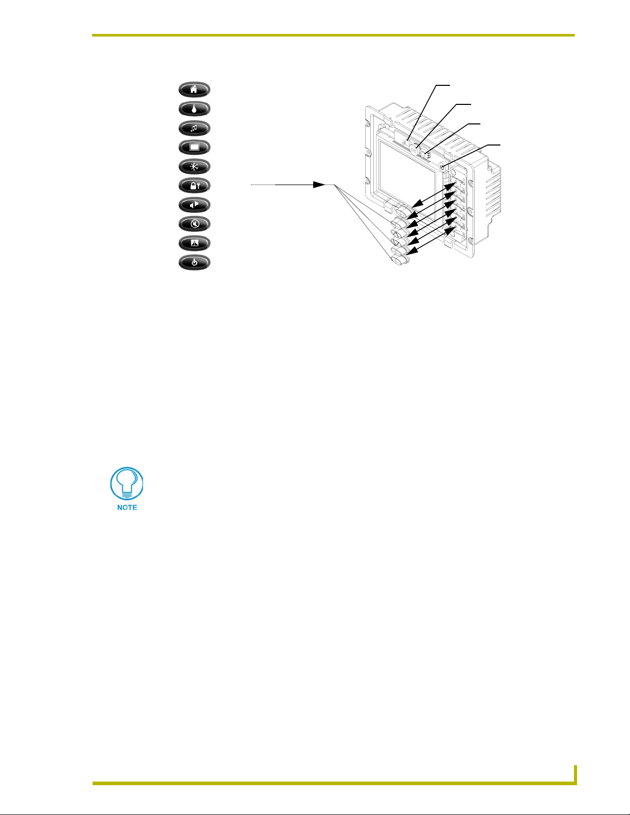
The following graphic (FIG. 3) indicates the locations of the different Wall Mount screw types.
Installation
Four Solid Surface
screws are used here
to secure the
housing/unit to a solid
surface
FIG. 3 Wall Mount panel (AXD) showing the secure locations for all screws types
Four (4) #4-20 screws
(thread-forming screws)
- these are used to secure
the internal components
to the housing
Four (4) #4-40 screws
(machine screws)
- these are used to
secure the housing to
a CB-CP4/A
Wall Mount installation using a pre-wall CB-CP4/A Conduit Box
The CP4/A Conduit/wallbox is an optional metallic housing that is installed onto a beam in a
pre-wall setting. The touch panels are housed in a default backbox that ships with each unit.
This installation (using the CB-CP4/A) must be done prior to any wall
installation.
To install a Wall Mount touch panel into a conduit/wallbox for pre-mounted surfaces:
1. Fasten the CB-CP4/A to the stud through the stud fastening holes shown in FIG. 4 on page 8.
The wallbox can be secured to the stud by using either nails or screws.
4" Color Touch Panels with Audio
7
Page 12
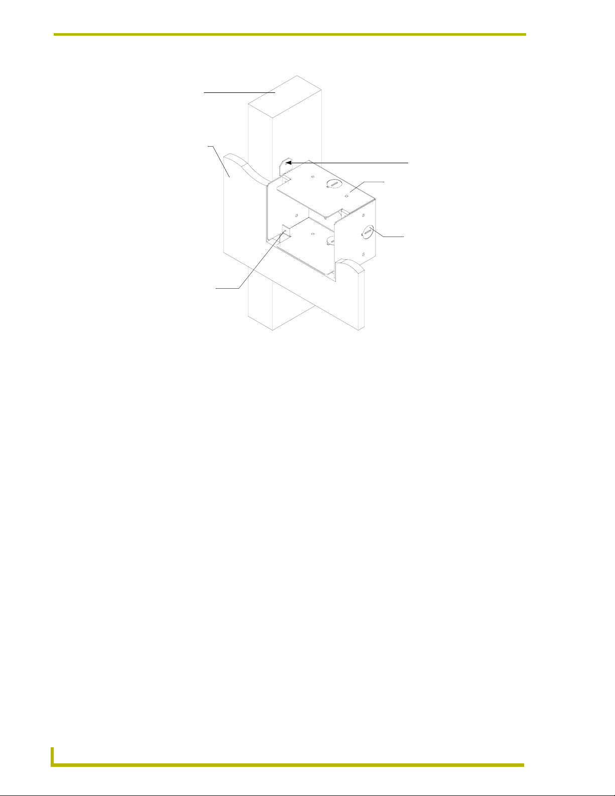
Installation
Stud
Surface
Stud fastening holes
CB-CP4/A Conduit Wallbox
Knockouts
AXD-CP4/A touch
panel housing secure
locations using four
#4-40 screws
Do not use these tabs
to mount a Conduit/
Wallbox
FIG. 4 Screw location for attachment on a sample conduit box for a drywall installation
2. Remove any necessary wiring knockouts from the pre-installed (optional) conduit box
(C in FIG. 4 on page 8) where the necessary cables are threaded through for connection to the
touch panel and external devices. The snaps located along the side of the conduit/wallbox can
be snapped off or used to mount the unit to a hard surface (like a wooden beam).
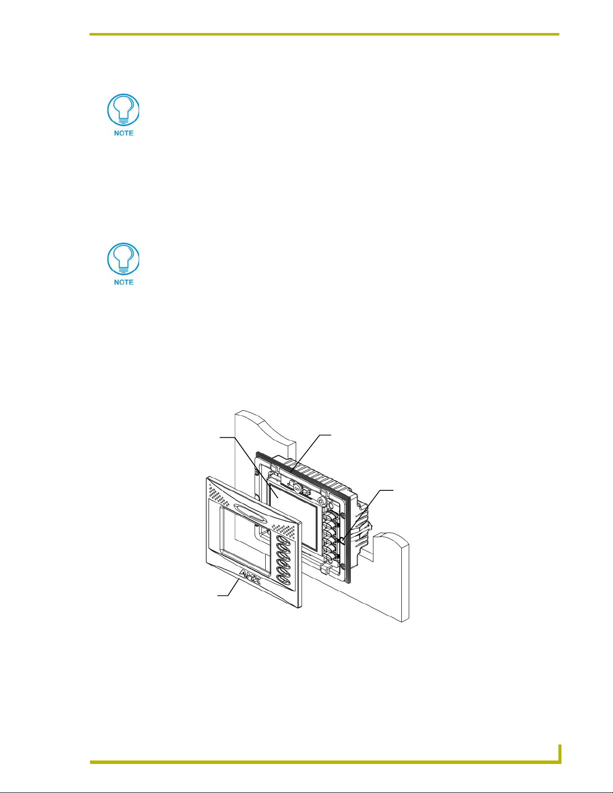
3. Carefully remove the attached AMX faceplate/bezel (A in FIG. 5) from the main AXD unit
(B in FIG. 5) by gripping the faceplate from the notches (located along the underside of the
plate) and pulling with gentle force.
4. Thread the incoming 4-pin mini-AXlink and 8-pin mini-Audio wiring through the cutout
opening in the wall.
5. Test the wiring by connecting the 4-pin mini-Phoenix connector from the rear AXlink
connector to a PSN6.5 power supply or Central Controller. Verify that the panel is receiving
power and functioning properly to prevent repetition of the installation.
6. Connect both the AXlink and Audio connectors to the rear of the touch panel. Refer to the
Wiring the Touch Panel section on page 21 for more detailed wiring instructions.
7. Disconnect the power connector from the PSN6.5 or Central Controller until the installation is
complete.
8
4" Color Touch Panels with Audio
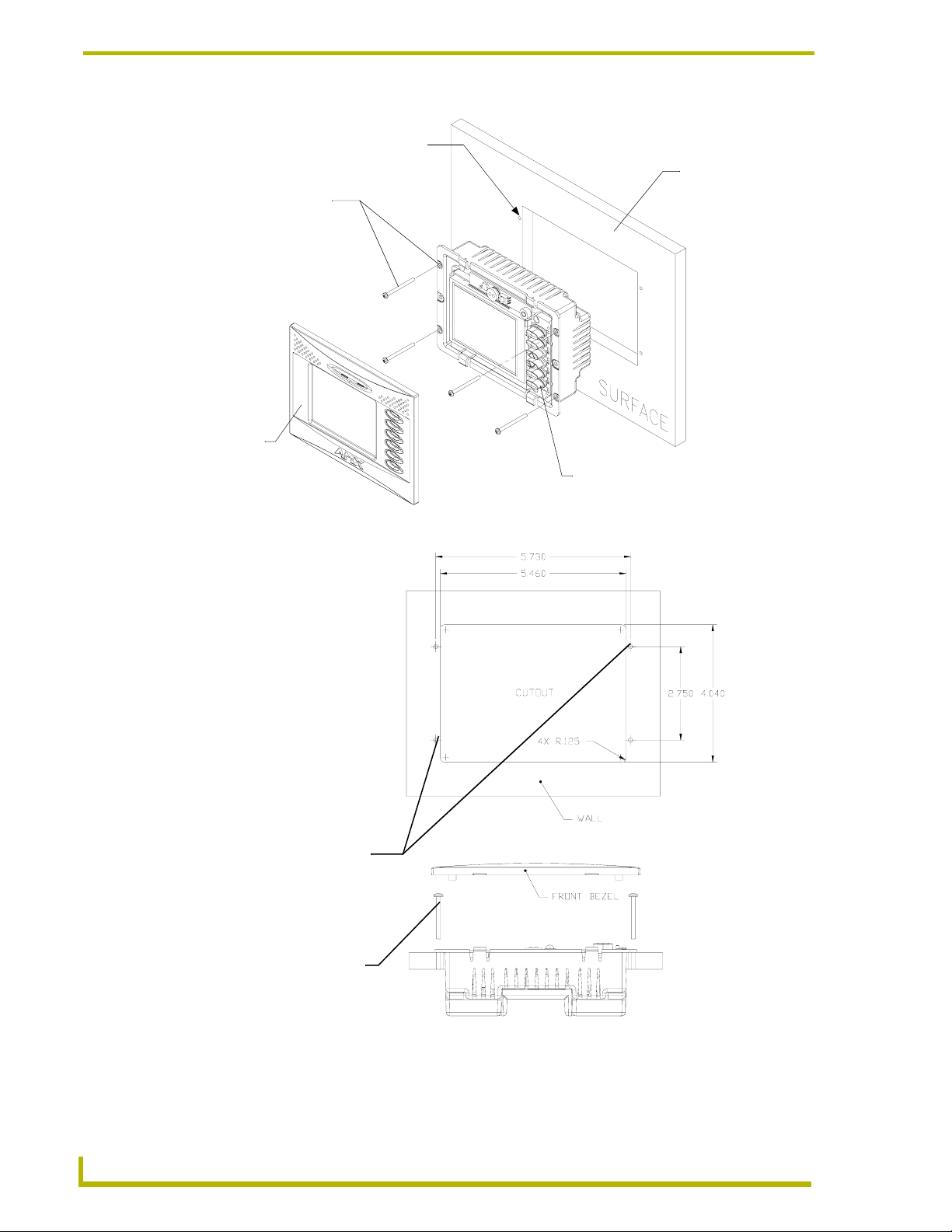
Page 13
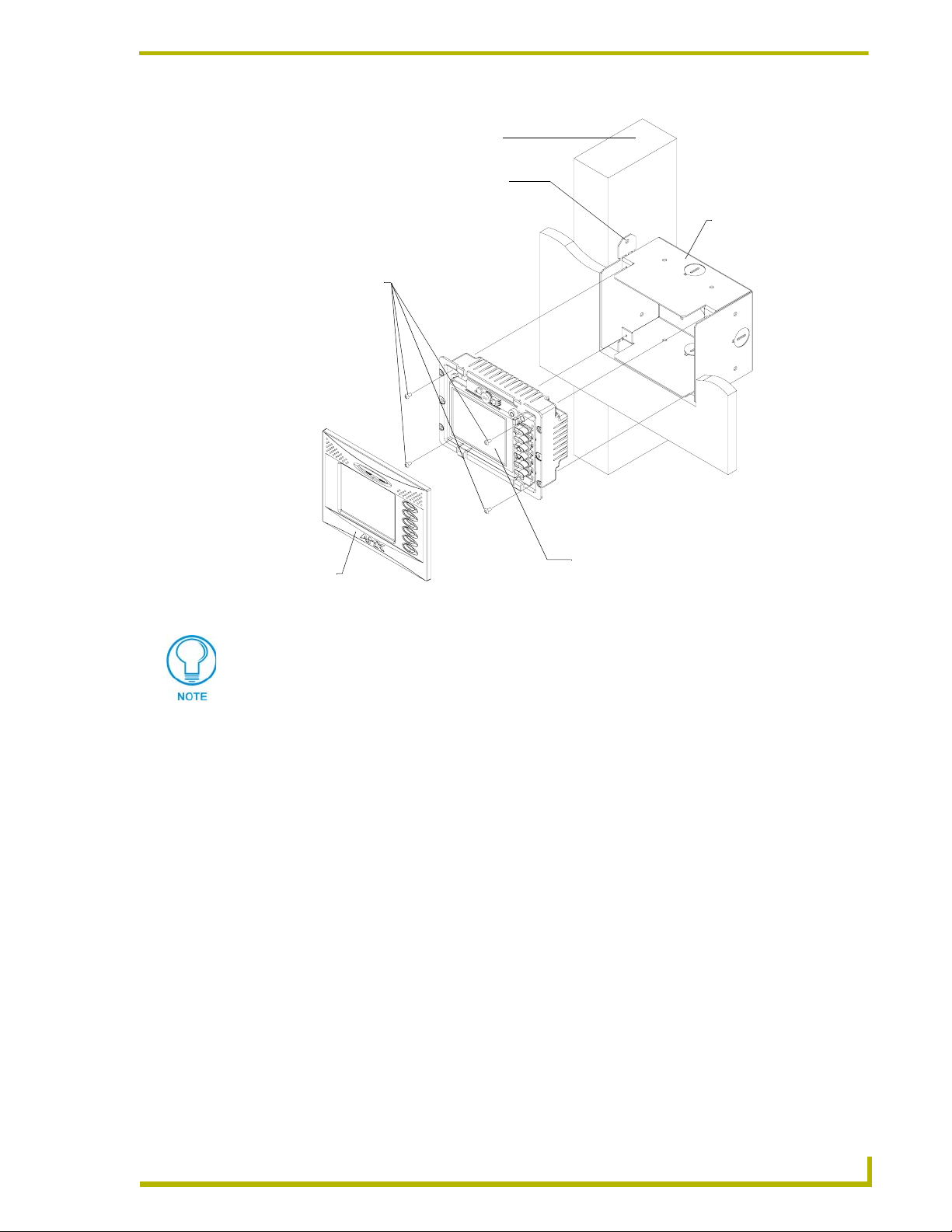
Attachment site for beam
Install the (4) #4-40
machine screws into
into the places
indicated
Installation
Stud beam
C - Optional CB-CP4/A
conduit/wallbox
SURFACE
A - Faceplate
(bezel)
FIG. 5 Wall Mount panel installation configuration for pre-existing conduit/wall box in a pre-wall construction
B - Main AXD unit consists of
the touch panel and backbox housing
Don’t disconnect the connectors from the touch panel. The unit must be installed with
the necessary connectors before being inserted into the drywall. Verify that the panel
is receiving power and functioning properly to prevent repetition of the installation.
8. Fasten the CB-CP4/A to the stud through the tabs shown in FIG. 5. The wallbox can be secured
to the stud by using either nails or screws. This installation must be done prior to any wall
installation.
9. Carefully slide the main unit (B in FIG. 5) into the conduit/wallbox (C in FIG. 5) until it slides
in completely and flush against the wallbox.
10. Use the four (4) securing screws (#4-40 screws) to attach the main AXD unit to the conduit
wallbox. Refer to B in FIG. 5 on page 9 for more information.
11. Use a grounded Phillips screwdriver to tighten the screws in a clockwise direction
12. Fasten the main AXD unit to the surface using the four (4) surface screws (not provided with
unit) until the housing is securely fastened and flush against the wall.
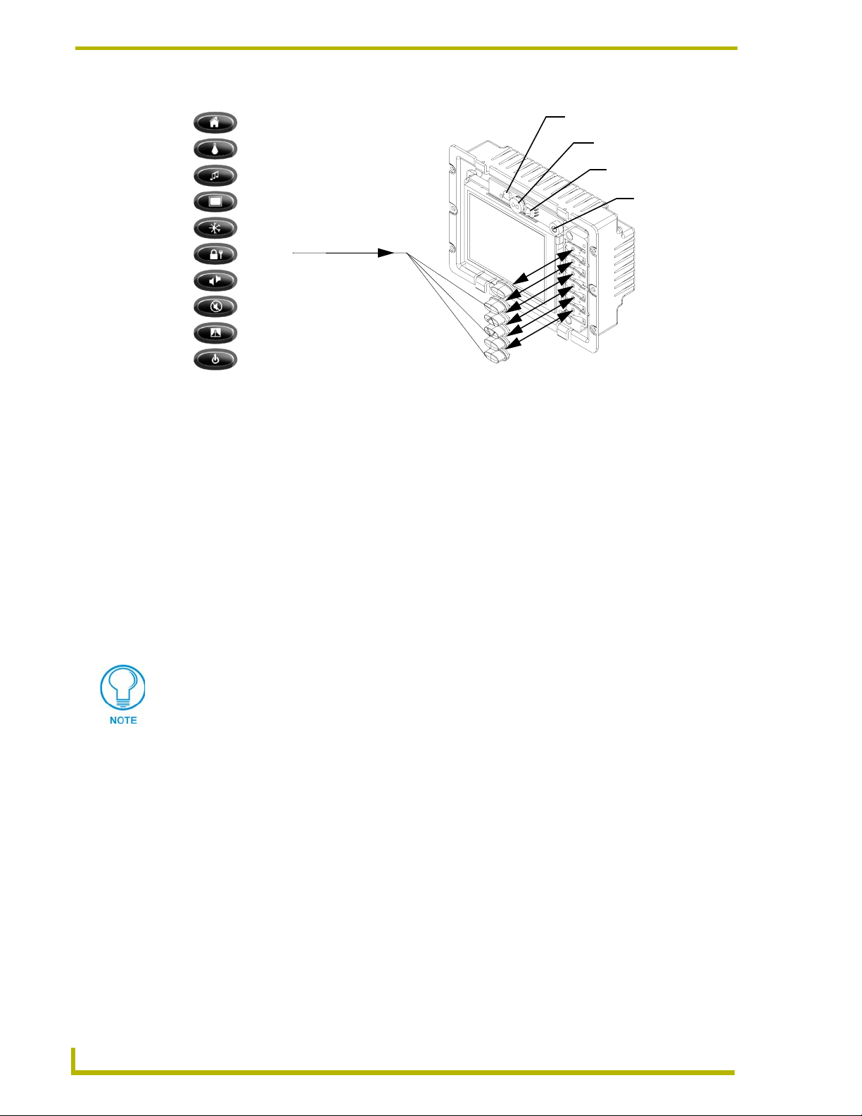
13. Carefully remove any of the blank pre-installed plastic pushbuttons by pushing the top rim of
the button towards the LCD panel and applying a small amount of force.
14. Carefully insert the six (6) desired replacement pushbuttons (up to 12 other pre-labeled buttons
come in the accessory button kit) by grabbing the button at either sides, inserting the
attachment pegs into their respective connector holes, and pressing down firmly (FIG. 6 on
page 10).
4" Color Touch Panels with Audio
9
Page 14
Installation
Menu
Lights
Audio
Video
Environment
Security
Intercom
Mute
Drapes
Powe r
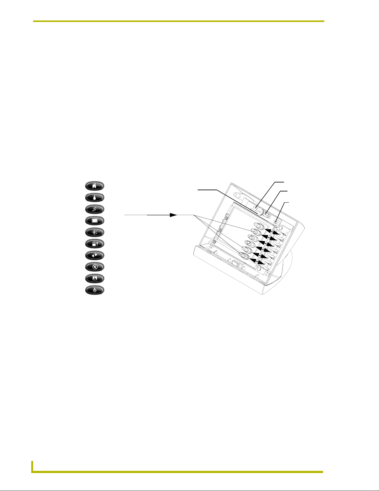
FIG. 6 Plastic pushbutton replacement locations
Standard pushbutton
icons (come in 3 colors
Black, Beige, and White)
Light Sensor
PIR (Passive Infrared)
Sensor
IR Receiver
Microphone
15. Place the faceplate (A in FIG. 5 on page 9) onto the main AXD unit (B in FIG. 5 on page 9) by
gripping the object at both sides, resting the top rim of the faceplate to the top rim of the
housing, then applying gentle downward force. Make sure to align the Light, IR receiver, and
PIR Motion sensor locations to their respective openings on the front bezel/faceplate. Make
sure the buttons are flush against the faceplate.
16. Reconnect the audio wiring to its respective terminal locations on the selected external audio
equipment for use in conferencing.
17. Reconnect the 4-pin mini-AXlink connector from the panel to the Central Controller and
provide power to the unit.
Wall Mount panel installation into Drywall using Expansion Clips
To install Wall Mount touch panels into plasterboard/drywall:
Expansion clips are mounted through pre-drilled notches located at the sides of the
panel. These clips are one-time use pieces. If and error occurs during the installation
process, a replacement clip must be ordered through your AMX representative.
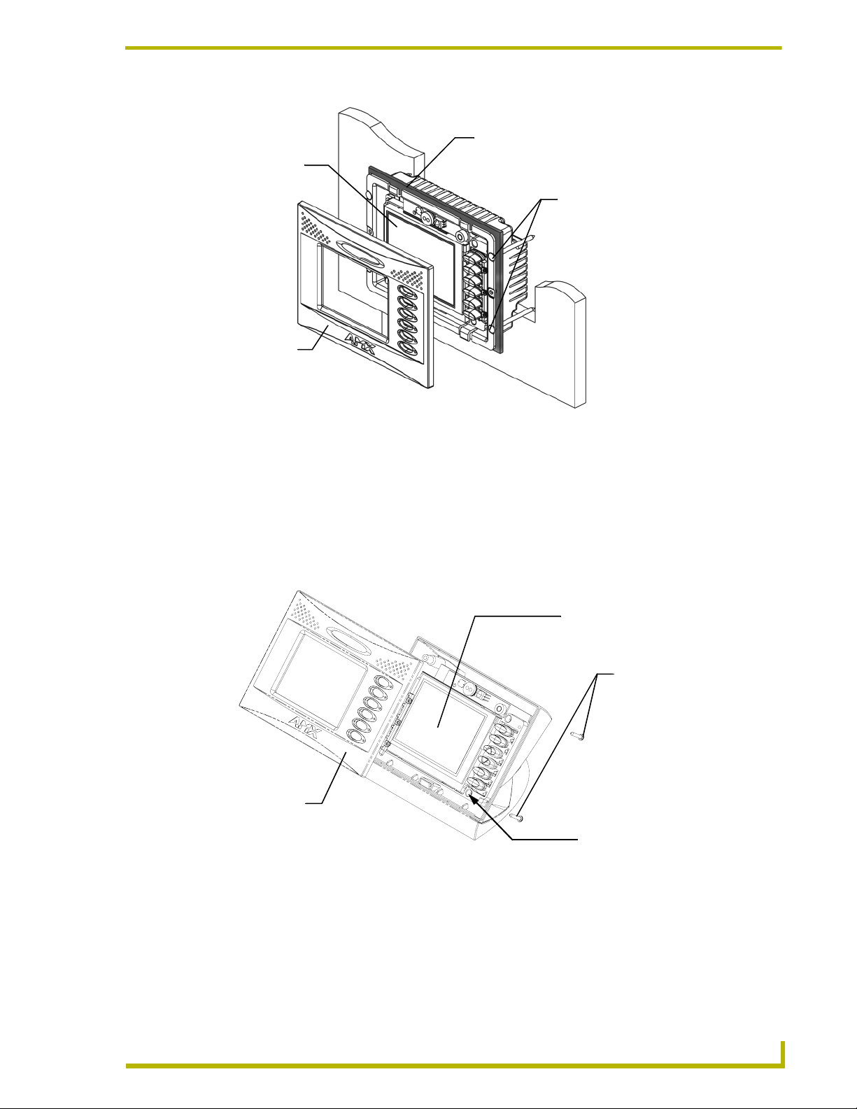
1. Carefully remove the attached AMX faceplate/bezel (A in FIG. 7 on page 11) from the main
AXD unit (B in FIG. 7 on page 11) by gripping the faceplate from the notches (located along
the underside of the plate) and pulling with gentle force.
2. Cut out the install surface using the dimensions shown in FIG. 8 on page 11. Cut out the two
notches along-side the CP4/A to accommodate the two provided drywall expansion clips.
3. Thread the incoming 4-pin mini-AXlink and 8-pin mini-Audio wiring through the cutout
opening in the wall.
4. Test the wiring by connecting the 4-pin mini-Phoenix connector from the rear AXlink
connector to a PSN6.5 power supply or Central Controller. Verify that the panel is receiving
power and functioning properly to prevent repetition of the installation.
5. Connect both the AXlink and Audio connectors to the rear of the touch panel. Refer to the
Wiring the Touch Panel section on page 21 for more detailed wiring instructions.
10
4" Color Touch Panels with Audio
Page 15
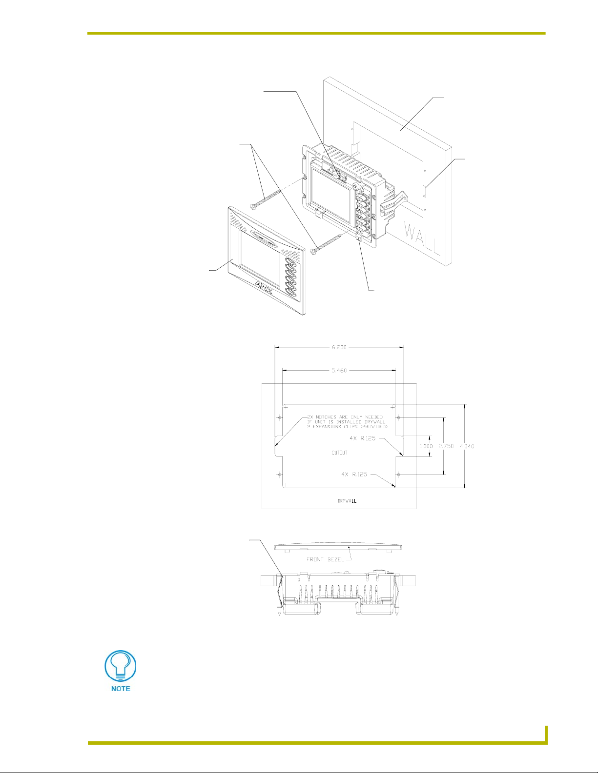
Installation
PIR, Microphone, IR and
Light Sensor locations
Install the 2-#6 drywall
clips and screws
(included) into the
the holes
A - Faceplate
(bezel)
B - Main AXD unit consists of the touch
panel, internal components, and housing
FIG. 7 Wall Mount panel (AXD) installation configuration for drywall surfaces
Flat surface
(can include a
wall, podium, or
other level
surface)
2 notches are
required if the unit
is installed into a
drywall using the (2)
provided clips.
Drywall clip set (clip and
screw) for installation
to plasterboard/drywall
FIG. 8 Wall Mount panel installation configuration for plasterboard
Don’t disconnect the connectors from the touch panel. The unit must be installed with
the necessary connectors before being inserted into the drywall. Verify that the panel
is receiving power and functioning properly to prevent repetition of the installation.
4" Color Touch Panels with Audio
surfaces
11
Page 16

Installation
6. Disconnect the power connector from the PSN6.5 or Central Controller until the installation is
complete.
7. Insert the #6 drywall screws and clips into the two notch locations along the side edges of the
Wall Mount housing as shown in both FIG. 7 on page 11 and in FIG. 8 on page 11.
8. Carefully insert the main unit (with expansion clips) into the cutout until the rim of the AXD
unit lies flush with the wall and the unit is firmly positioned.
9. Use a grounded Phillips screwdriver to tighten the #6 drywall screws in a clockwise direction
(FIG. 7 on page 11).
10. Fasten the main AXD unit to the surface using the two (2) drywall clip sets (consisting of
screws and clips) supplied with the enclosure until the housing is securely fastened and flush
against the wall (FIG. 9).
As the screw is tightened, the clip bends toward the insertion hole and into the wall. This
bending creates a "grip" on the wall by either pressing onto the wall or by securing the drywall
between the housing and the drywall clip.
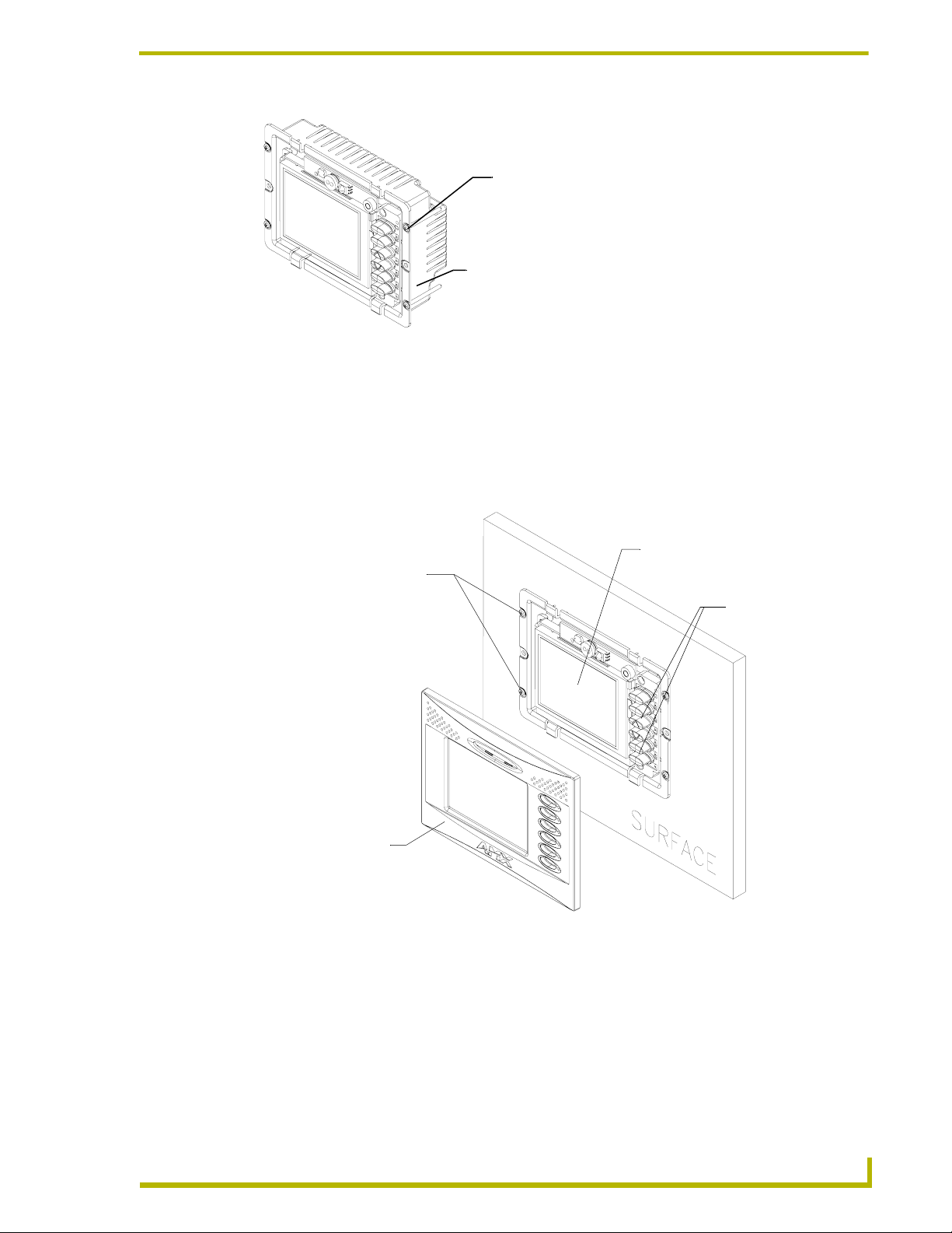
B - Main
AXD unit
Interchangeable
plastic pushbuttons
Dry wall clips and 2- #6 screws
are inserted through the
notches cut out in the wall
A - Faceplate
(bezel)
FIG. 9 Screw and clip locations for plasterboard (dry wall) mounting of main AXD unit
11. Carefully remove any of the blank pre-installed plastic pushbuttons by pushing the top rim of
the button towards the LCD panel and applying a small amount of force.
12. Carefully insert the six (6) desired replacement pushbuttons (up to 12 other pre-labeled buttons
come in the accessory button kit) by grabbing the button at either sides, inserting the
attachment pegs into their respective connector holes, and pressing down firmly (FIG. 10 on
page 13).
12
4" Color Touch Panels with Audio
Page 17
Installation
Menu
Lights
Audio
Video
Environment
Security
Intercom
Mute
Drapes
Powe r
FIG. 10 Plastic pushbutton replacement locations
Standard pushbutton
icons (come in 3 colors
Black, Beige, and White)
Light Sensor
PIR (Passive Infrared)
Sensor
IR Receiver
Microphone
13. Place the faceplate (A in FIG. 9 on page 12) onto the main AXD unit (B in FIG. 9 on page 12)
by gripping the object at both sides, resting the top rim of the faceplate to the top rim of the
housing, then applying gentle downward force. Make sure to align the Light, IR receiver, and
PIR Motion sensor locations to their respective openings on the front bezel/faceplate. Make
sure the buttons are flush against the faceplate.
14. Reconnect the audio wiring to its respective terminal locations on the selected external audio
equipment for use in conferencing.
15. Reconnect the 4-pin mini-AXlink connector from the panel to the Central Controller and
provide power to the unit.
Wall Mount panel installation onto a flat surface using solid-surface screws
Mounting screws are secured through four (4) pre-drilled holes located at the left and
right sides of the panel.
1. Carefully remove the attached AMX faceplate/bezel (A in FIG. 11) from the main AXD unit
(B in FIG. 11) by gripping the faceplate from the notches (located along the underside of the
plate) and pulling with gentle force.
2. Cut out the surface using the dimensions shown in FIG. 12 on page 14. Be sure not to cut out
notches for the expansion clips (only used when mounting the panel in plasterboard).
3. Thread the incoming 4-pin mini-AXlink and 8-pin mini-Audio wiring through the cutout
opening in the wall.
4. Test the wiring by connecting the 4-pin mini-Phoenix connector from the rear AXlink
connector to a PSN6.5 power supply or Central Controller. Verify that the panel is receiving
power and functioning properly to prevent repetition of the installation.
5. Connect both the AXlink and Audio connectors to the rear of the touch panel. Refer to the
Wiring the Touch Panel section on page 21 for more detailed wiring instructions.
6. Disconnect the power connector from the PSN6.5 or Central Controller until the installation is
complete.
4" Color Touch Panels with Audio
13
Page 18
Installation
Install the four (4)
solid surface screws
into the holes
(screws not included)
shown below.
Screw length
depends on the
installation surface.
A
- Decor
faceplate
Attachment is done
along the edges of
the cutout
Flat/Solid surface
(can include a
wall, podium, or
other level
surface)
B - Main AXD unit consists of the
touch panel, internal components,
and housing
FIG. 11 Wall Mount panel installation configuration for flat /solid surfaces
These four holes are only
required when mounting
to a solid surface. Secure
the unit with solid surface
screws using #4-40 threaded
inserts at these four locations
Solid surface screw inserts
(4 screws) for mounting to a
flat surfaces (provided by
installer)
14
FIG. 12 Wall Mount panel installation configuration for flat surface mounting
7. Insert the four solid surface screws into the four threaded insert locations along the side edges
of the Wall Mount housing as shown in both FIG. 13 on page 15.
4" Color Touch Panels with Audio
Page 19
Installation
Solid surface mounting screws (4)
are inserted through the
outer holes along the plastic housing
Main AXD unit consists of
internal components, CP4/A, and
plastic housing
FIG. 13 Screw locations for plasterboard mounting of the main AXD unit
8. Carefully insert the main unit (with surface screws) into the cutout until the rim of the AXD
unit lies flush with the wall and the unit is firmly positioned.
9. Use a grounded Phillips screwdriver to tighten the solid surface screws in a clockwise direction
(FIG. 13 on page 15).
10. Fasten the main AXD unit to the surface using the four (4) solid surface screws (not provided
with unit) until the housing is securely fastened and flush against the wall (FIG. 14).
Solid surface mounting screws
are inserted through the
openings along the side of
the Wall Mount panel
A - Faceplate
(bezel)
FIG. 14 Mounting screw locations for solid-surface mounting of main AXD unit
B - Main
AXD unit
Interchangeable
plastic pushbuttons
11. Carefully remove any of the blank pre-installed plastic pushbuttons by pushing the top rim of
the button towards the LCD panel and applying a small amount of force.
12. Carefully insert the six (6) desired replacement pushbuttons (up to 12 other pre-labeled buttons
come in the accessory button kit) by grabbing the button at either sides, inserting the
attachment pegs into their respective connector holes, and pressing down firmly (FIG. 15 on
page 16).
4" Color Touch Panels with Audio
15
Page 20
Installation
Menu
Lights
Audio
Video
Environment
Security
Intercom
Mute
Drapes
Powe r
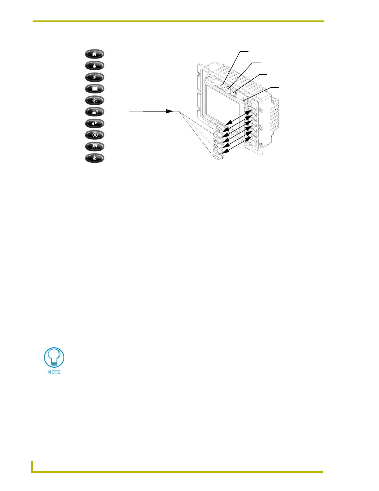
FIG. 15 Plastic pushbutton replacement locations
Standard pushbutton
icons (come in 3 colors
Black, Beige, and White)
Light Sensor
PIR (Passive Infrared)
Sensor
IR Receiver
Microphone
13. Place the faceplate (A in FIG. 14) onto the main AXD unit (B in FIG. 14) by gripping the
object at both sides, resting the top rim of the faceplate to the top rim of the housing, then
applying gentle downward force. Make sure to align the Light, IR receiver, and PIR Motion
sensor locations to their respective openings on the front bezel/faceplate. Make sure the buttons
are flush against the faceplate.
14. Reconnect the audio wiring to its respective terminal locations on the selected external audio
equipment for use in conferencing.
15. Reconnect the 4-pin mini-AXlink connector from the panel to the Central Controller and
provide power to the unit.
Installation of the AC-CP4A/WRB Faceplates
AMX now offers a new option - a set of water-resistant bezels for AXD-CP4/A touch panels:
AC-CP4A/WRB. This faceplate set includes all three (3) color configurations - beige, black, and
white - covered with a thin transparent water-resistant film that covers the entire surface of the
bezel including the touch screen, sensor lens, and pushbuttons. It also includes a rubber-foam
gasket to "seal" the gap between the bezel, the back box and the wall. It is a perfect solution that
brings the power of AMX touch panels into wet and splashy environments inside your house or
office building.
The AC-CP4A/WRB is intended for installation to AXD units.
The two main installation environments where this accessory can be used are: Solid
surface (using four #4-40 solid surface screws) and Drywall surface
(using 2 - #6 drywall clips and screws).
16
4" Color Touch Panels with Audio
Page 21
Installation
Drywall Surface upgrade installation
Expansion clips are mounted through pre-drilled notches located at the sides of the
panel. These clips are one-time use pieces. If and error occurs during the installation
process, a replacement clip must be ordered through your AMX representative.
1. Carefully remove the attached AMX faceplate/bezel (A in FIG. 16) from the main AXD unit
(B in FIG. 16) by gripping the faceplate from the notches (located along the underside of the
plate) and pulling with gentle force.
2. Locate the 2 drywall screws located along both sides of the AXD unit.
3. Use a grounded Phillips screwdriver to slightly loosen the #6 drywall screws in a counter-
clockwise direction.
The purpose of only slightly loosening the drywall screws is NOT to remove the unit
but to provide enough slack so that there is enough room between the AXD housing
and the drywall to wrap the foam insulation around the back of the housing for
insulation purposes.
4. Unscrew the drywall screws enough to where there is a 0.125" gap between the edge of the
AXD housing and the drywall.
5. Install the foam insulation by inserting the left side of the foam between the drywall and the
rear of the housing.
6. While still holding the insulation, gently pull the other side of the foam over the opposite side
of the housing (FIG. 16) until the entire foam strip is now located behind the outer rim of the
AXD housing.
B - Main unit
(with LCD)
A - Faceplate
(bezel)
Foam Insulation strip
Two #6 drywall
clips and screws
FIG. 16 Foam insulation location on a drywall mounted AXD
7. Verify the alignment of the center foam cutouts over the two side drywall screws (FIG. 16).
8. Carefully begin tighten the #6 drywall screws in a clockwise direction. Slight adjustments to
the position of the foam insulation can be necessary.
4" Color Touch Panels with Audio
17
Page 22

Installation
9. Perform a visual inspection of the insulation seal around the rim of the AXD housing. There
should be no visible gaps between the rim of the housing and the surface of the drywall.
10. Finish the securing process of the AXD back to the drywall by tightly turning the drywall
screw in a clockwise direction to guarantee a tight seal.
11. Place the new AC-CP4A/WRB water-resistant faceplate onto the main AXD unit
(B in FIG. 16) by gripping the object at both sides, resting the top rim of the faceplate to the
top rim of the housing, then applying gentle downward force.
12. Make sure to align the Light, IR receiver, and PIR Motion sensor locations to their respective
openings on the front bezel/faceplate. Make sure the buttons are flush against the faceplate.
Solid Surface upgrade installation
Expansion clips are mounted through pre-drilled notches located at the sides of the
panel. These clips are one-time use pieces. If and error occurs during the installation
process, a replacement clip must be ordered through your AMX representative.
1. Carefully remove the attached AMX faceplate/bezel (A in FIG. 17) from the main AXD unit
(B in FIG. 17) by gripping the faceplate from the notches (located along the underside of the
plate) and pulling with gentle force.
2. Locate the 4 solid-surface screws located along both sides (2 per side) of the AXD unit.
3. Use a grounded Phillips screwdriver to slightly loosen the screws in a counter-clockwise
direction.
The purpose of only slightly loosening the surface screws is NOT to remove the unit
but to provide enough slack so that there is enough room between the AXD housing
and the surface to wrap the foam insulation around the back of the housing for
insulation purposes.
4. Unscrew the screws enough to where there is a 0.125" gap between the edge of the AXD
housing and the surface.
5. Install the foam insulation by inserting the left side of the foam between the surface and the
rear of the housing.
6. While still holding the insulation, gently pull the other side of the foam over the opposite side
of the housing (FIG. 17) until the entire foam strip is now located behind the outer rim of the
AXD housing.
7. Verify the alignment of the center foam cutouts over the four side solid-surface screws
(FIG. 17).
8. Carefully begin tighten the screws in a clockwise direction. Slight adjustments to the position
of the foam insulation can be necessary.
9. Perform a visual inspection of the insulation seal around the rim of the AXD housing. There
should be no visible gaps between the rim of the housing and the surface.
18
10. Finish the securing process of the AXD back to the surface by tightly turning the surface screw
in a clockwise direction to guarantee a tight seal.
11. Place the new AC-CP4A/WRB water-resistant faceplate onto the main AXD unit (B in
FIG. 17) by gripping the object at both sides, resting the top rim of the faceplate to the top rim
of the housing, then applying gentle downward force.
4" Color Touch Panels with Audio
Page 23
Installation
Foam Insulation strip
B - Main unit
(with LCD)
4 - #4-40 solid
surface screws
A - Faceplate
(bezel)
FIG. 17 Foam insulation location on a solid surface mounted AXD
12. Make sure to align the Light, IR receiver, and PIR Motion sensor locations to their respective
openings on the front bezel/faceplate. Make sure the buttons are flush against the faceplate.
Removing the AXT Faceplate/Bezel
Whereas the AXD faceplate is removable by gripping the faceplate from the notches and pulling
outwards, the AXT faceplate is secured to the enclosure via four (4) #4-40 phillips-head screws
located along the rear corners of the panel (FIG. 18).
B - Main AXT unit consists of
the touch panel, internal components
and enclosure
Remove/Install the four (4)
#4-20 screws from/into the
location indicated
A - Faceplate
(bezel)
Securing screws (4) #4-20
FIG. 18 AXT faceplate removal and screw locations
1. Flip the AXT panel over and place the LCD onto a soft cloth to prevent scratching during the
removal process.
2. Locate the four (4) phillips-head #4-20 screws on the rear of the enclosure.
3. Remove the screws by inserting a grounded Phillips screwdriver into the screw holes and turn
the screws counter-clockwise.
4" Color Touch Panels with Audio
19
Page 24
Installation
4. Remove all screws from the rear of the unit (B in FIG. 18 on page 19).
5. Firmly grab the front and rear of the panel and flip it back to where the entire unit is lying flat
on a level surface.
6. Carefully pull the faceplate (A in FIG. 18 on page 19) outwards until it comes away from the
rest of the main AXT unit (B in FIG. 18 on page 19).
Refer to the following section for more information on removing/replacing the pushbuttons and
reconnecting the faceplate/bezel to the main AXT unit
Removing and replacing AXT pushbuttons
1. Carefully remove any of the blank pre-installed plastic pushbuttons by pushing the top rim of
the button towards the LCD panel and applying a small amount of force.
2. Carefully insert the desired replacement pushbutton (up to 12 other pre-labeled buttons come
in the accessory button kit) by grabbing the button at either sides, inserting the attachment pegs
into their respective connector holes, and pressing down firmly (FIG. 19).
Menu
Lights
Audio
Video
Environment
Security
Intercom
Mute
Drapes
Powe r
FIG. 19 Plastic pushbutton replacement locations on AXT
Standard pushbutton
icons (come in 3 colors
Black, Beige, and White)
PIR (Passive
Infrared Sensor
Light Sensor
IR Receiver
Microphone
3. Carefully place the faceplate (A in FIG. 18) back onto the Main AXT unit (B in FIG. 18).
Make sure to align the Light, IR receiver, and PIR Motion sensor locations to their respective
openings on the front bezel/faceplate.
4. Firmly grab the front and rear of the panel and flip the AXT panel over.
5. Place the LCD back onto a soft cloth to prevent scratching during the removal process.
20
6. Insert all screws back into the screw holes on the rear of the unit (B in FIG. 18).
7. Secure the screws by inserting a grounded Phillips screwdriver into the screw holes and turn
the screws clockwise.
8. Firmly grab the front and rear of the panel and flip it back to where the entire unit is lying flat
on a level surface.
4" Color Touch Panels with Audio
Page 25
Installation
Wiring the Touch Panel
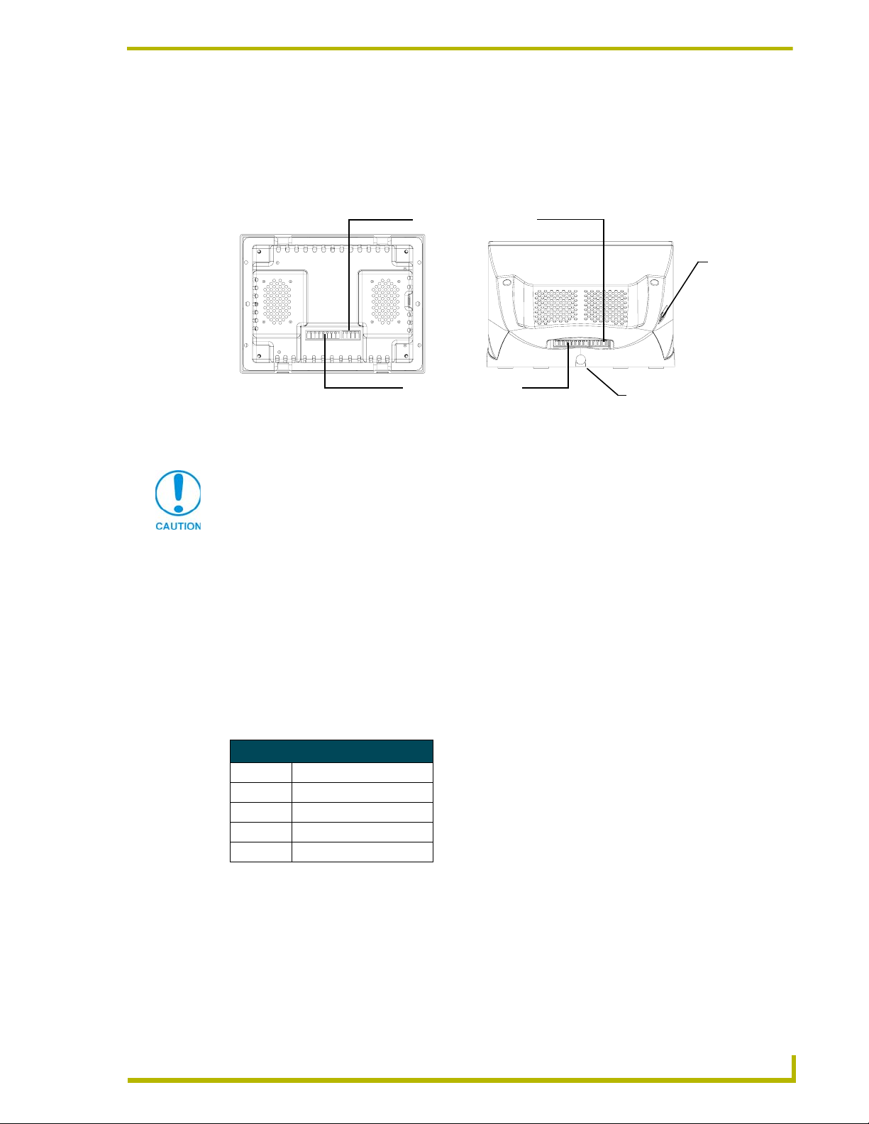
The CP4/A touch panels use a 4-pin 3.5 mm mini-Phoenix AXlink connector (male) for both power
and data and an 8-pin 3.5 mm mini-Phoenix connector for audio input/output (FIG. 20). This same
figure shows the rear connector locations on both AXD and AXT panels.
4-pin
3.5 mm mini-Phoenix
AXlink connector
Programming
jack
8-pin
3.5 mm mini-Phoenix
Audio connector
AXD-CP4/A (Rear view)
FIG. 20 Rear views of the AXD and AXT touch panels
AXT-CP4/A (Rear view)
Cable clip
Do not connect power to the touch panel until wiring is complete. If you are using a
12 VDC power supply, apply power to the touch panel only after installation is
complete.
Wiring guidelines
CP4/A touch panels require 12 VDC power to operate properly. These panel can use either a
PSN2.8 or a PSN6.5 power supply. The Central Controller supplies power via the AXlink cable.
The maximum wiring distance between the Central Controller and touch panel is determined by
power consumption, supplied voltage, and the wire gauge used for the cable. The table below lists
wire sizes and maximum lengths allowable between the touch panel and Central Controller. The
maximum wiring lengths for using AXlink power are based on a minimum of 13.5 volts available at
the Central Controller’s power supply. Refer to the Specifications section on page 1 for more
information.
Wiring Guidelines at 770 mA
Wire Size Maximum Wiring Length
18 AWG 152.43 feet (46.46 m)
20 AWG 96.44 feet (29.39 m)
22 AWG 60.13 feet (18.33 m)
24 AWG 37.90 feet (11.55 m)
4" Color Touch Panels with Audio
21
Page 26
Installation
Wiring the CP4/A terminal connectors and cables
You will need a wire stripper and Phillips screwdriver to prepare and connect the captive wires.
Power and Audio connectors are wired and attached to the rear of the CP4/A. FIG. 21 provides a
layout of the wiring connection into both the AXD and AXT touch panels. This diagram is intended
for use in wiring the terminal ends of the 4-pin and 8-pin cables.
Microphone (-)
Microphone (+)
Mic GND
3.5 mm Audio Connector
Terminal connections are
dependent on the system configuration
FIG. 21 CP4/A terminal connector pinout and wiring diagram
8-pin
4-pin
3.5 mm mini-AXlink
Audio Right (+)
Audio Right (-)
Audio GND
Audio Left (+)
Audio Left (-)
GND
AXM
AXP
PWR
AXD/T-CP4/A
Rear
Front
Touch
Panel
On an AXT-CP4/A panel, these terminal connections are already wired to the
appropriate connectors. To wire the terminal end of the AXT panel, connect the
connectors to the rear of the panel as shown in FIG. 21 and thread the tabletop cable
(CA5921-01) through the cable support clip located at the base of the panel (rear).
1. Loosen the screws on both the 4-pin and 8-pin connectors before insertion.
2. Strip 0.25 inch of wire insulation off all wires.
3. Insert the incoming PWR, AXP, AXM, and GND wires from the Controller’s AXlink
connector into the respective openings on the terminal 4-pin 3.5 mm mini-Phoenix AXlink
connector locations shown in FIG. 21.
4. Insert the outgoing microphone and incoming audio wires from the existing audio system into
the respective openings on the terminal 8-pin 3.5 mm mini-Phoenix audio connector locations
shown in FIG. 21.
5. Secure the connections by using a grounded Phillips screwdriver to turn the screws clockwise.
Do not over-torque the screws; doing so can bend the seating pin and damage the connector.
6. Insert the wired connectors to the rear of the CP4/A touch panel.
Do not connect power to the touch panel until wiring is complete. If you are using a
12 VDC power supply, apply power to the touch panel only after installation is
complete.
7. Unscrew the two (2) screws that attach the clip to the underside of the AXT.
8. Thread the tabletop cable through the cable-clip opening at the rear of the AXT unit
(FIG. 20 on page 21).
22
4" Color Touch Panels with Audio
Page 27

Installation
9. Flip the AXT panel over and place the LCD onto a soft cloth to prevent scratching during the
removal process.
10. Screw the two (2) screws that attach the clip to the underside of the AXT.
11. Firmly grab the front and rear of the panel and flip it back to where the entire unit is lying flat
on a level surface.
Additional CP4/A wiring configurations
FIG. 22 provides a layout of the wiring connection used for multiple CP4/A panels wired to both a
Central Controller and an Audio switch. This diagram is intended for use in general wiring amongst
the various components of this system. The audio and microphone termination connectors are
dependent on the switch itself.
AXlink
AXlink
AXlink
AXlink
AXlink
AXD/T-CP4/A
Tou ch
Panel
#1
AXD/T-CP4/A
Tou ch
Panel
#2
AXD/T-CP4/A
Tou ch
Panel
#3
AXD/T-CP4/A
Tou ch
Panel
#N
Central Controller
(Master)
Microphone
Audio
Wire
termination is
switch dependent
Microphone
Audio
Microphone
Audio
Microphone
Audio
A
U
D
I
O
S
W
I
T
C
H
Wire termination are
dependent on the switch connections
FIG. 22 CP4/A wiring diagram using multiple panels routed through a Master and audio switch
In the above system, panel #1 could be configured so that a push sends a corresponding command
through the Master that sets panel #1’s microphone On and then sets all other panels (#2 - N) to
transmit the audio through their speakers.
An example of this would be if a user wants to use panel #1 to send a page throughout a
home/office: "is anyone there...". All other panels would transmit the audio being picked
up by the first panels’ microphone.
4" Color Touch Panels with Audio
23
Page 28

Installation
Another example used with this system is that a user, upon hearing the page, could press
a button "labeled" for the source room and respond: "yes, I’m here".
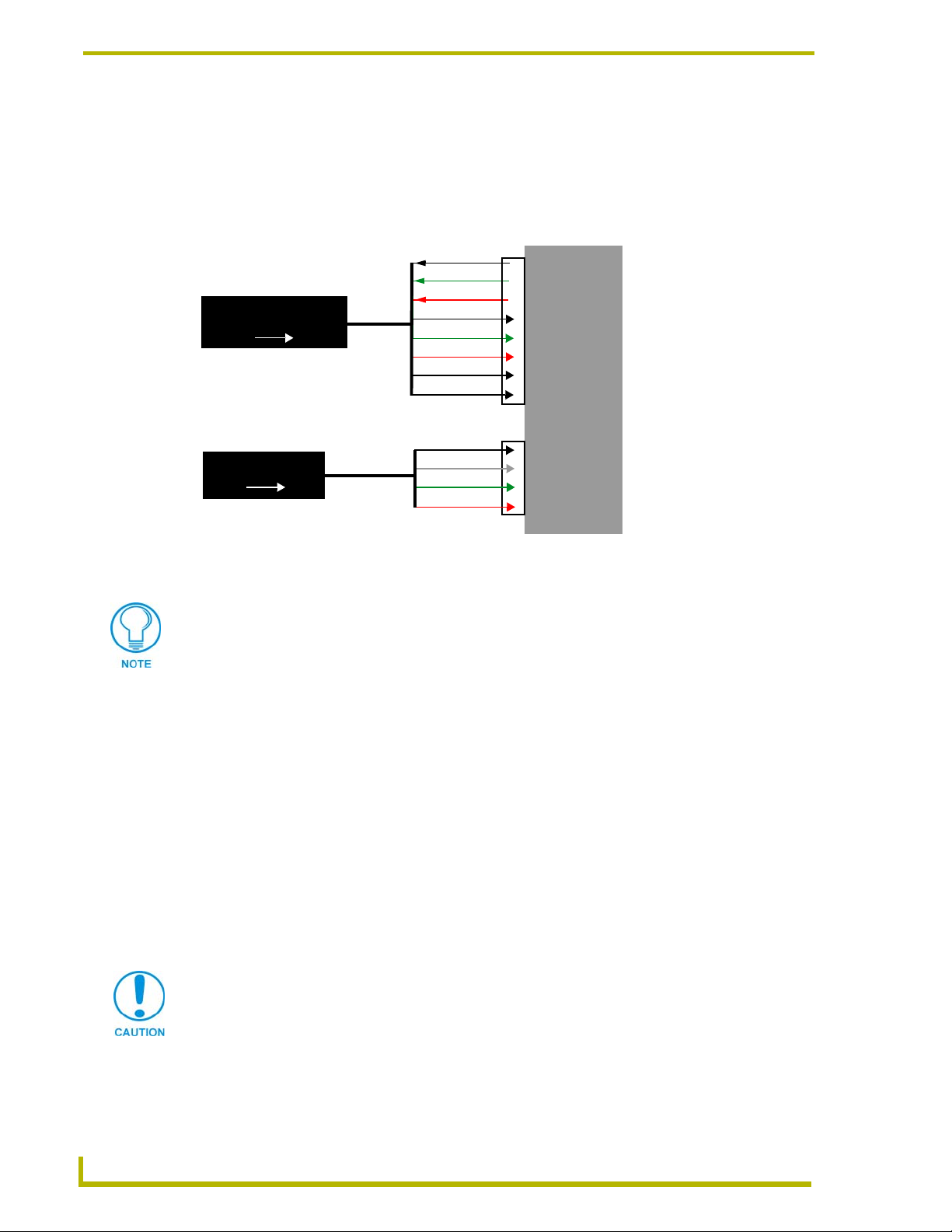
FIG. 23 provides a layout of the wiring connection using two directly cross-connected CP4/A
panels that use a Master. This diagram is intended for use in general wiring information amongst
the various components of this system.
Central Controller
(Master)
Mic
Speaker
AXD/T-CP4/A
Touch
Panel
#1
Audio
4-pin AXlink
8-pin AXlink
Mic
AXD/T-CP4/A
Tou ch
Panel
Audio
Mic
#2
Speaker
A
U
Wire termination of the Mic and Audio is
done using an 8-pin 3.5 mm mini-Phoenix connector
FIG. 23 CP4/A wiring diagram using two panels directly connected to each other using the CA5921-01 cable
D
I
In the above example, the Master controls the volume activity of the audio being transmitted
(through the microphone on one panel) and received (through the speakers of the other panel). The
mini 4-pin AXlink cable connects the panels to the Master and the mini 8-pin cable connects the
two panels’ audio signals.
The following bullets explain what happens on the panels during an audio transmission from both
the first and second panel.
A button push on panel #1 sends a PUSH command to the Master which then:
Increases panel #1 microphone level and mutes panel #1 speaker. This allows the
first user to transmit audio.
Decreases panel #2 microphone level and increases Panel #2 speaker volume to
default levels. This allows the second user to hear the audio being transmitted from
panel #1.
24
A button push on panel #2 sends a PUSH command to the Master which then:
Increases panel #2 microphone level and mutes panel #2 speaker. This allows the
second user to transmit audio.
Decreases panel #1 microphone level and increases Panel #1 speaker volume to
default levels. This allows the first user to hear the audio being transmitted from
panel #1.
4" Color Touch Panels with Audio
Page 29

Installation
Using the CP4/A Programming Jacks
The programming jack (located on the side of either AXT or AXD touch panels) is used for
programming/communication between the CP4/A touch panel and TPDesign3. The programming
jack uses a three-wire, 2.5 mm stereo port. The optional (female to female) Axcess programming
cable (FG10-727) is used to bridge the connection between the programming cables’ male terminal
connector and the male RS-232 port on the rear of your PC (FIG. 24).
AXT Programming
jack
Stereo plug
(male)
CP4/A panel
to DB9
programming
cable (FG10-817)
FIG. 24 Programming jack connector locations and wiring configuration to the PC
AXD Programming
jack
or
male DB9
female DB9
female DB9
Axcess Programming
cable - FG10-727
goes to your PC’s
rear male RS-232
port
To download and upload TPDesign3 touch panel pages:
1. Connect the stereo plug (male) end of the programming cable into the programming jack on
the side of the CP4/A.
2. Connect the male DB9 end of the cable into the female connector on the optional Axcess
programming cable.
3. Connect the other end of the Axcess programming cable to the male DB9 port on the back of
your computer.
4. Configure the communication parameters in TPDesign3.
For more information on CP4/A communication methods, refer to the Communication
Methods for CP4/A Firmware Update section on page 67 for additional methods and
firmware download procedures.
4" Color Touch Panels with Audio
25
Page 30

Installation
26
4" Color Touch Panels with Audio
Page 31

Designing Touch Panel Pages
There are two ways to approach creating touch panel pages:
TPDesign3 - Refer to the TPDesign3 Touch Panel Program (Version 3. 16) instruction
manual for more information.
On-board editor
This section describes the basics of using the on-board editor to create pages and buttons. For more
information, refer to the G3 Firmware Design and Reference instruction manual.
Verify the TPDesign3 program being used is Version 3.16 build 193 or higher.
The Updated EXE for TPDesign3 can be found at AMX.com > Tech Center >
Downloadable Files > Application FIles > TPDesign3. Earlier versions of TPD3
will not correctly function with these panels.
Buttons
Standard button types include rectangles and other geometric shapes you can create with the touch
panel editor. Buttons are set with attributes, meaning there is a response from the Central Controller
when you touch the button.
Designing Touch Panel Pages
General buttons are part of the default touch panel program and cannot be changed. General buttons
create or revise pages and specify panel communication parameters. The general button categories
are described in the table below.
General Button Categories
Selection buttons Selection buttons appear on touch panel pages and set
communication parameters.
Information buttons Information buttons contain serial numbers and firmware version
Adjustment buttons You can use the UP and DN buttons to set adjustment buttons. The
Keypad buttons The keypad button opens a keypad so you can enter a password or
information. The properties of these buttons cannot be changed.
These buttons have a dark fill and light text.
adjustment button example sets the baud rate for the connection
from the touch panel to the computer.
value assignment. All keypad buttons are interactive except for the
entry display.
4" Color Touch Panels with Audio
27
Page 32

Designing Touch Panel Pages
General Button Categories (Cont.)
Decision buttons Decision buttons appear when an operation has two options and
Status buttons Status buttons always have a dark fill with light letters and have no
Operation bars Operation bars appear in the place of the Editor bar, after selecting a
Touch to Continue buttons "Touch to Continue" buttons appear when an operation requires user
Joystick buttons Joysticks are vertical and horizontal direction controllers for use with
requires verification before an action is performed.
functionality except to display information.
button or page edit operation. The operation bar indicates which edit
function is currently active. When an edit operation is selected, it
remains active until you press EXIT.
acknowledgement.
pan and tilt camera controllers.
Bargraph buttons Bargraph buttons display a dynamic bargraph (vertical or horizontal).
An example is the Battery level indicator button.
Activating Edit Mode
Before designing touch panel pages and buttons, you must activate Edit mode. Once activated, use
the
EDIT button to enter Edit mode. This mode has options to add and configure touch panels and
buttons. When powering up the touch panel, the first page is the Main page (FIG. 25). Note that the
Edit button is not available initially. If you have a pre-programmed panel, you may not see the Main
page.
28
FIG. 25 Main Page
To activate Edit mode:
1. Press
2. Press
SETUP in the Main page to open the Setup page (FIG. 26).
PROTECTED SETUP to open the keypad.
4" Color Touch Panels with Audio
Page 33

Designing Touch Panel Pages
FIG. 26 Setup page
3. Enter 1988 (default password) in the keypad and press ENTER to open the Protected Setup
page. If you press ENTER after typing an incorrect password, you are immediately returned to
the previous page.
4. Press
EDITOR to enable the Edit mode. The EDITOR button is highlighted in the Protected
Setup page when enabled, as shown in FIG. 27.
FIG. 27 Protected Setup page with the active EDITOR button
5. Press
6. Press
EXIT to close the Protected Setup page and return to the Setup page (now in Edit mode).
EXIT again to return to the Main page. The EDIT button appears at the top of the page
indicating Edit mode is active.
7. Press
EDIT to open the Edit bar. The BUTTON and PAG E options, in the Edit bar (FIG. 28), are
used to design and modify button and page settings.
Setting the Device Base
Press the DEVICE BASE option, in the Protected Setup page (FIG. 27), to assign a base (starting)
device address to the touch panel.
1. Enter the base address for the touch panel. The base address range is from 1 - 255. Standard
device addresses begin at 128.
2. Press
4" Color Touch Panels with Audio
ENTER to save.
29
Page 34

Designing Touch Panel Pages
FIG. 28 Main page with Edit bar
Setting the Device Used
Use the DEVICE USED option in the Protected Setup page (FIG. 27) to assign a value for the
number of devices being controlled by the touch panel.
Edit bar
1. Press
DEVICE USED to open the keypad and enter the panel’s device number from 1 - 4. Each
device number supports up to 255 programmable channel codes. The multiple device settings
allow you to create up to four unique touch panel buttons and/or pages. This value is used to
determine the current device being used by the panel.
2. Enter the number of devices being used by the touch panel.
3. Press
ENTER to save the value.
Adding a Page
1. Press PAG E on the Edit bar to open the PA GE menu.
2. Press
3. Press
Setting the page color
1. Press
2. Press
3. Press
4. Select a color from the palette; the page automatically changes to the new color.
ADD to open the keyboard and enter a name for the new page. Page names can be up to
20 characters.
EXIT CHANGE to save, close the keyboard, and go to the new page.
EDIT to open the Edit bar on the newly created page.
PAG E on the Edit bar to open the PAG E menu.
PAG E C OL O R to open the color palette.
30
Adding a Button
To add a button to the current page:
1. Press
2. Press
BUTTON on the Edit bar to open the BUTTON menu.
ADD to open the ADD BUTTON operation bar. On the LCD screen, touch and drag to
create a button. The first touch point is the upper-left corner of the button.
4" Color Touch Panels with Audio
Page 35

Resizing a button
Designing Touch Panel Pages
1. Press
2. Press
BUTTON on the Edit bar to open the BUTTON menu.
RESIZE. Then, touch any edge of the button and drag. Removing your finger from the
panel saves the button dimensions.
Defining On-Screen Button Properties
External pushbuttons are configured with features similar to on-screen buttons. Their functionality
can be set just as any other button on the touch panel.
Use the
button colors for channel on/off conditions, channel/variable text codes, and string/macro
assignments.
Although the Border and Color sections of this page appear, they are of no use to external
pushbuttons since they do not appear on-screen.
To set button properties:
1. Press
2. Press
3. Press the new button to open the Button Properties page. This page lists the properties for the
4. Press
PROPERTIES option of the BUTTON menu in the Edit bar to set button borders, page flips,
BUTTON on the Edit bar to open the BUTTON menu options.
PROPERTIES to open the PROPERTIES operation bar.
active button.
BUTTON TYPE to open the BUTTON TYPE menu.
5. Choose a button type for the selected button to open the associated Button Properties page.
Each button type has its own Button Properties page with settings specific to the button.
6. Press
7. Select a border to set for the button and return to the Button Properties page. The
BORDER to open the Button Border page.
BORDER
button changes to show the selected border type.
Setting the channel code
The channel button sets the device and button channel codes.
Channel codes and variable text codes work the same for all button types, including
joysticks, and bargraphs.
1. In the Button Properties page, press
DEV to open the keypad and set the touch panel’s device
number.
2. Enter 1, 2, 3, or 4 in the keypad. The programming software uses device codes 1 - 4 to identify
the touch panel. Refer to the G3 Firmware Design and Reference instruction manual for more
information.
If DEVICE USED is set to 4 and Base Device Number is 128, the Controller recognizes
bus devices 128 - 131.
The panel will not allow you to enter a device number greater than the DEVICE USED
without first displaying a decision box asking if you accept the new selection or not.
3. Press
ENTER to save the device number, close the keypad, and return to the Button Properties
page.
4" Color Touch Panels with Audio
31
Page 36

Designing Touch Panel Pages
4. Press CHAN to open the keypad and enter a channel value of 1 - 255. The source code uses the
channel code number to identify the button and its programmed operations. The channel code
for non-active buttons is 0.
5. Press
ENTER to save the channel number, close the keypad, and return to the Button Properties
page.
Setting the variable text code
The variable text buttons set the device and button channel codes for the buttons.
1. Press
DEV to open the keypad and set the device number.
2. Enter 1, 2, 3, or 4 in the keypad. The source code uses device codes 1 - 4 to identify the touch
panel.
3. Press
4. Press
ENTER to save, close the keypad, and return to the Button Properties page.
CHAN to open a keypad and set the channel number.
5. Enter a channel value of 1 - 255 in the keypad. The source code uses the channel code number
to identify the button and its operations.
6. Press
ENTER to save the channel number, close the keypad, and return to the Button Properties
page.
Setting the page flip
1. Press the Page
the
PAGE FLIP TYPE menu.
Page FLIP
type button
FLIP STANDARD type button (FIG. 29) in the Button Properties page to open
Flip to Page button
FIG. 29 Page FLIP Type button
2. Select a Page Flip type. If you select
P
AGE button appears.
3. Press the
FLIP TO PAGE button (FIG. 29) to open a list of all the saved touch panel pages. If the
FLIP PREVIOUS in the PAGE FLIP TYPE menu, the FLIP TO
desired page is not present in the menu, check to verify the page has been saved.
4. Select the target page for the page flip.
Setting the button colors for channel-off conditions
1. Press any button to open the Button Properties page.
2. Press
BORDER under CHANNEL OFF in the Button Properties page. The color palette appears.
Select a color to set as the border.
3. Press the
FILL button in the Button Properties page to open the palette. Select a color to set as
the fill.
4. Press the
5. Press
TEXT button to open the palette. Select a color to use for the text.
EXIT SAVE CHANGE in the Button Properties page to save the new button properties and
return to the current page.
32
4" Color Touch Panels with Audio
Page 37

Adding text, icons, and bitmaps to a button
Designing Touch Panel Pages
1. Press
2. Press
BUTTON on the Edit bar to open the BUTTON menu.
TEXT/IMAGE to add text to the button. The TEXT/IMAGE operation bar appears.
3. Press any button to open the Text/Image page.
4. Go through each option and set as desired:
TEXT OFF and TEXT ON sets the text for the button's Off and On state.
ICON OFF and ICON ON sets the icon for the button's Off and On state.
BITMAP OFF and BITMAP ON sets the bitmap for the button's Off and On state.
MAKE ON SAME AS OFF sets the On and Off properties the same.
You cannot create or edit buttons with Unicode fonts on the panel. Any use of the
TEXT/IMAGE button to alter or create Unicode font supported buttons must be done
in the TPDesign3 Touch Panel Design Program.
5. Press
EXIT SAVE CHANGE to close the Text/Image page and return to the Main page.
Creating a Bargraph and Joystick
Bargraphs are level monitors and adjustable level controls. These levels can be configured to
monitor and adjust audio outputs and lighting levels.
Joysticks are vertical and horizontal direction controllers you can use for things such as camera pan
and tilt control. Before starting, make sure to connect the touch panel to your Controller; otherwise,
the joystick will not work properly.
Adding a bargraph or joystick button
Create a new button using the Add operation bar in the
1. Press
2. Press
BUTTON in the Edit bar to open the BUTTON menu.
PROPERTIES in the Button menu to open the PROPERTIES operation bar.
BUTTON menu.
3. Press any button to open the Button Properties page.
4. Press
BUTTON TYPE to open the BUTTON menus. Choose a button type to open its Button
Properties page.
Setting Bargraph and Joystick Properties
Use the Button Properties page to set channel, level, and button colors. Refer to the Setting the
variable text code section on page 32 and the Setting the channel code section on page 31 for
further information. Refer to the Setting the button colors for channel-off conditions section on
page 32 for more information on colors for channel-off conditions.
4" Color Touch Panels with Audio
33
Page 38

Designing Touch Panel Pages
Setting the level code
Level buttons set the device and number codes for the touch panel.
Joysticks use two level numbers. The first is for the X-axis and the second for the
Y-axis. You only need to specify the first level.
1. Press
DEV to open a keypad and set the device number.
2. Enter 1, 2, 3, or 4 in the keypad. The programming software uses device codes
1 - 4 to identify the touch panel.
3. Press
ENTER to save the level device number, close the keypad, and return to the Button
Properties page.
4. Press
NUM to open a keypad and set the level number assigned to the device.
5. Enter a number 1 – 8. Each device can have from 1 – 8 levels except joysticks, where the range
is 1 – 7.
6. Press
ENTER to save, close the keypad, and return to the Button Properties page.
Using the Adjust Sensors Setup Page
The button illumination, infrared, microphone, speakers, and light sensors on the CP4/A panels
come factory defaulted with values that can be changed by each user to suit their needs. Refer to
the Programming section on page 41 for more detailed information on commands.
This page is used to configure the various features and parameters for the CP4/A panel sensors. To
access the Sensors Setup page:
1. From the Main page press the
2. Press
ADJUST SENSORS from the Setup page (FIG. 26 on page 29).
SETUP button.
3. Choose from any of the sensor setup buttons on the Adjust Sensors page (FIG. 30).
FIG. 30 Adjust Sensors page
4. Calibrate the following sensors before the system is used.
PIR SENSOR adjusts the effective sensitivity (physical detection range) of the Passive
Infrared Sensor. The activation threshold range of the
PIR SENSOR is 1 - 20. An
34
4" Color Touch Panels with Audio
Page 39

Designing Touch Panel Pages
adjustment to the PIR activation threshold is also achieved through the use of the IRSL
AXlink Send_Command. Refer to page 47 for more information.
Setting the value to zero forces the value to 1. Disabling of the PIR is done by disabling
both the Infrared Push/Release and the Infrared Wake features. Refer to the
PUSH/RELEASE
INFRARED STATUS displays the activity of the infrared sensor. This button toggles
and WAKE button descriptions for more information.
INFRARED
between the available On/Off states; depending on whether there is an activation of the
sensor. When an object crosses the activation range of the sensor, the button turns to the
On state.
INFRARED PUSH enables an Input/Output change that is sent to the AXlink program.
This feature is independent of the other infrared features such as
can be disabled by entering an
INFRARED CHANNEL value of zero or through the use of
INFRARED WAKE. This
the IRPU AXlink Send_Command. Refer to page 47 for more information. Sample uses
of this feature include the illumination control of room lights. The following occurs when
this feature is active:
On the initial detection of a user within the range of the PIR, an I/O change of TRUE
(Push) is sent to the AXlink program.
If the presence of a user has been detected and the PIR no longer senses the presence
of a user for a period of thirty (30) seconds; an I/O change of FALSE (Release) is
sent to the AXlink program.
The PIR I/O change is always disabled when in the Adjust Sensors Mode.
INFRARED WAKE turns On the backlight of the display when the PIR detects the
presence of a user. This feature is disabled through the use of the IRWA AXlink
Send_Command. Refer to page 47for more information.
DIM MODE BRIGHTNESS adjusts the brightness of the touch panel backlight for the
Dim-Room (DRM) mode operation. The Dim-Room brightness level range is 1 - 8. An
adjustment to the Dim-Room brightness level is also achieved through the use of the
BRDM AXlink Send_Command. Refer to page 45 for more information.
AUDIO AND IR DEVICE SETUP provides the speaker volume control, microphone
control, and the IR device codes. Refer to the Using the Adjust Sensors Setup
Page section on page 34 for more information.
LIGHT DIM MODE sets the Light Sensor to automatically switch the touch panel display
backlight between a Normal-Room (NRM) or Dim-Room (DRM) setting (active when
the
LIGHT DIM MODE button is pressed). This feature is disabled through the use of the
LSDM AXlink Send_Command. Refer to page 48 and the LS Level # definition below
for more information.
4" Color Touch Panels with Audio
In the Normal-Room mode, the brightness of the panel is the same as the value set in
the Setup > Set Brightness page.
In the Dim-Room mode, the brightness of the backlight is user selectable through the
DIM MODE BRIGHTNESS level setting on the Adjust Sensors page.
35
Page 40

Designing Touch Panel Pages
INFRARED DEVICE # assigns a device number to the Passive Infrared sensor. An
INFRARED CHANNEL # assigns a channel number to the Passive Infrared sensor. An
LS DEVICE # assigns a device number to the Light sensor.
LS LEVEL # assigns a level number to the light sensor.
If Light Sensor levels are scaled to values of 1 - 127, it indicates a Dim Room Mode.
Values of 128 - 255 indicate a Normal Room Mode.
PIR BUTTON ILLUMINATION mode sets the pushbutton LEDs to illuminate when the
adjustment to the Infrared Device value is also achieved through the use of the IRPU
AXlink Send_Command. Refer to page 47 for more information. CP4/A Device numbers
are also configured through TPDesign3.
adjustment to the Infrared Channel value is also achieved through the use of the IRPU
AXlink Send_Command. Refer to page 47 for more information. CP4/A Channel
numbers are also configured through TPDesign3. Refer to the TPDesign3 Touch Panel
Design instruction manual for more information.
Passive Infrared sensor (PIR) detects the presence of a user. When the PIR no longer
detects the presence of a user (after thirty seconds), the pushbutton LED illumination
turns Off. An adjustment to this mode is also achieved through the use of the PBIL
AXlink Send_Command. Refer to page 49 for more information.
Illumination is dependent only on the PIR. It does not matter whether the panel is in
Wake/Sleep mode or whether the Light Sensor is set to Dim-Room mode (DRM) or
Normal-Room mode (NRM).
LS BUTTON ILLUMINATION mode sets the pushbutton LEDs to illuminate when the
light sensor (LS) falls below its threshold value. In the case of a Dim-Room, refer to the
light sensor section above for more information about the definition of a Dim vs. Normal
Room. When the LS rises above its hysteresis (turn-on) value, in the case of a
Normal-Room, the pushbutton LED illumination turns Off. An adjustment to this mode
is also achieved through the use of the PBIL AXlink Send_Command. Refer to page 49
for more information.
LED illumination is dependent only on the LS and corresponding light threshold. It
does not matter whether the panel is in Wake/Sleep mode or whether the Light
Sensor is set to DRM or NRM.
BUTTON ILLUMINATION mode sets the pushbutton LEDs to either illuminate (On) or
not (Off). An adjustment to this mode is also achieved through the use of the PBIL
AXlink Send_Command. Refer to page 49 for more information.
PIR/LS AUTO mode is a combination of the first two automatic mode buttons (PIR and LS
button illumination). An adjustment to this mode is also achieved through the use of the
PBIL AXlink Send_Command. Refer to page 49 for more information.
The order of precedence for illumination of the pushbutton LEDs is PIR then LS.
The pushbutton LEDs illuminate if there is PIR activity, without regard to the level
36
4" Color Touch Panels with Audio
Page 41

Designing Touch Panel Pages
of the light sensor. The LEDs also illuminate if there is no PIR activity and the light
sensor level falls below its threshold value.
The order of precedence for turning Off the pushbutton LEDs is the LS then PIR. If
the light sensor rises above its hysteresis (turn-on) value and there is no any activity
coming from the PIR (thirty seconds of inactivity), the LEDs turn Off.
Using the Audio and IR Device Setup page
The speaker volume control, microphone control, and the IR device codes will be facilitated
through a Audio And IR Device Setup Page. This page is used to configure the various features and
parameters for the CP4/A panel sensors. To access the Sensors Setup page:
1. From the Main page press the
2. Press
3. Press
ADJUST SENSORS from the Setup page (FIG. 26 on page 29).
AUDIO AND IR DEVICE SETUP from the Adjust Sensors page (FIG. 30 on page 34).
SETUP button.
4. Choose from any of these buttons and sliders to alter and set the properties for the speakers, IR
receiver, and microphone (FIG. 31 on page 37).
FIG. 31 Adjust Sensors page
SPEAKER VOLUME allows the user to adjust the effective speaker volume. The panel
consists of an up button (UP), a down button (DN), and a current setting indicator (range
is between 0 and 32). The Speaker Volume up and down buttons adjust the Speaker
Volume. A zero value will mute the speaker. An adjustment to the speaker volume is also
achieved through the use of the SVOL AXlink Send_Command. Refer to page 50 for
more information.
MICROPHONE ADJUSTMENT allows the user to adjust the effective microphone
volume. The panel consists of an up button (UP), a down button (DN), and a current
setting indicator (range is between 0 and 32). The Microphone Adjustment up and down
buttons adjust the Microphone Volume. A zero value will mute the microphone. An
adjustment to the speaker volume is also achieved through the use of the MVOL AXlink
Send_Command. Refer to page 48 for more information.
4" Color Touch Panels with Audio
37
Page 42

Designing Touch Panel Pages
SPEAKER DEVICE # assigns a device number to the speaker. Enter a device number
SPEAKER LEVEL # assigns a level number to the speaker. Enter a level value of
IR CODES DEVICE # allows a user to enable/disable the IR feature. This toggles the
MICROPHONE DEVICE # assigns a device number to the microphone. Enter a device
from 1 -4 into the on-screen Keypad and press ENTER when done.
1 - 8 into the on-screen Keypad and press ENTER when done.
selection such that activating the button enables the IR Codes Device feature and
de-activating ("reverse video") disables the IR Codes Device feature.
The device number (n) displayed on the IR Codes Device button is one greater than the
number shown on the device used button on the protected setup page. This device number
is then added to the device base shown on the audio and IR Device Setup page and is used
when the IR codes are received and sent to the Master.
Example: If device base equals 128, device used equals four, and the IR Codes
Device feature is toggled On, then the IR Codes Device button will show five and the
IR device will be 132. When the IR Codes Device button is toggled off the IR Codes
Device will indicate zero.
number from 1 -4 into the on-screen Keypad and press ENTER when done.
MICROPHONE LEVEL # assigns a level number to the microphone. Enter a level value
of 1 - 8 into the on-screen Keypad and press ENTER when done.
External PushButtons
The functionality of these external pushbuttons is like those of other touch panels. The assignments
for these pushbuttons include Device/Channel numbers, Flip to Page options, and a string/macro
option. The properties for these buttons is set from the
in touch panel Edit mode. Refer to the G3 Firmware Design and Reference instruction manual for
more information on working with the firmware.
Setting the pushbutton LED illumination
The external pushbuttons LEDs are backlit via the illumination buttons on the Sensor Setup page of
the touch panel. The user can choose from five different illumination modes from a combination of
the three lower buttons on the Adjust Sensors page:
AUTO
. Refer to page 34 through page 36 for more information on these modes.
To activate the Button LED Illumination modes:
1. Press
ADJUST SENSORS from the Setup page.
2. Press the combination of the three illumination buttons that correspond to the method of
desired illumination.
The above mentioned illumination modes are also set through the use of AXlink Send_Commands.
Refer to the System Send_Commands section on page 43.
EDIT > BUTTON > PROPERTIES menu while
ON, OFF, PIR AUTO, LS AUTO, and PIR/LS
38
4" Color Touch Panels with Audio
Page 43

Designing Touch Panel Pages
Light Sensor
The CP4/A is equipped with a photo-sensitive sensor that gives the panel the ability to
automatically switch the brightness of the display’s backlight between two settings: Normal Room
(NRM) and Dim-Room (DRM). The panel’s backlight is the amount of light emanating from the
buttons and LCD display.
Normal-Room mode is equal to the brightness of the backlight directly selectable from
the
SET BRIGHTNESS button in the Setup page.
Dim-Room mode allows the user to directly select the brightness value of the backlight
from the Sensors Setup page >
ADJUST SENSORS button.
Passive Infrared Sensor
The on-board infrared sensor provides motion detection that either "wakes-up" the CP4/A (Infrared
Wake) or sends an I/O signal to the Central Controller (Infrared Push/Release). This sensor is
mostly used for the illumination/non-illumination of the LCD, external backlit pushbuttons, and use
in the Push/Release control of room lights. The Adjust Sensors page displays a level indicator and
buttons that allow the user to change the following PIR settings: Infrared Wake, Infrared Push/
Release, Activation threshold.
IR Receiver
The CP4/A is equipped with an on-board IR receiver that is capable of receiving a one-way 38 KHz
signals (of AMX codes only). The properties for this receiver is capable of being set through
the Using the Adjust Sensors Setup Page section on page 34. The maximum range is 15 feet
(4.57 m) for the AXT and 22 feet (6.71 m) for the AXD unit. Reception angles vary dependant
upon the elevation and location of the installed panel.
Audio Tones
The CP4/A is equipped with a transducer that gives the panel the ability to both produce six
different audible tones and deliver sounds from other connected CP4/A panels. The tones are
enabled through the use of the BEEP AXlink Send_Command. Refer to the BEEP n s section on
page 45 for more detailed information about the tones and their specifications.
Speaker Volume
The speaker volume can be set through either the Speaker Volume section of the Using the Adjust
Sensors Setup Page section on page 34 or via the use of commands such as SVOL AXlink
Send_Command. Refer to the Using the Audio and IR Device Setup page section on page 37.
Microphone
The on-board microphone provides a user with the ability to transmit audio from one CP4/A touch
panel to another connected panel on a system. Refer to the Wiring the Touch Panel section on
page 21 for more information on panel wiring diagrams. These transmitted signals can be
configured to transmit to either specific panels or all panels on a system. The microphone volume
can be set through either the Microphone Adjustment section of the Using the Adjust Sensors Setup
4" Color Touch Panels with Audio
39
Page 44

Designing Touch Panel Pages
Page section on page 34 or via the use of commands such as MVOL AXlink Send_Command.
Refer to the Using the Audio and IR Device Setup page section on page 37.
Using TPDesign3 to Download Bitmaps, Icons, and Fonts
TPDesign3 allows you to download bitmaps, icons, and fonts into your touch panel from an
existing touch panel program. Touch Panel programs are created in the TPDesign3 software
program. Refer to the TPDesign3 Touch Panel Program instruction manual for more information.
Use the Download to Panel button to download a project file.
To download bitmaps, icons and/or fonts from an existing TPDesign3 project file:
1. Launch the TPDesign3 software program and open a project file that contains the desired
bitmaps, icons, and fonts.
2. Select File from the menu bar to open the File menu.
3. In the File menu, click on Download to Panel; this opens the Download to Panel dialog box.
4. Click on the Comm Settings tab to set the communications port, baud rate, and other
communication settings.
5. Then, click the Actions tab to set the communication mode and select which elements of the
project file you want to download to the touch panel.
6. In the What To Send area, select one or more of the available options (All Bitmaps, All Icons,
All Fonts).
7. Select the mode of communication with the touch panel (RS-232 or AXlink). Confirm that the
correct panel is selected by verifying the ID values with the Base Address assigned to the touch
panel in the Protected Setup page.
8. After clicking Connect, the Available Panels list appears in the Available Panels field. Click
Begin to start downloading the project file into the panel.
9. After completing the download, the bitmaps, icons and fonts that were downloaded are now
accessible via the BITMAPS, ICONS and FONTS menus.
40
4" Color Touch Panels with Audio
Page 45

Programming
You can program the touch panel, using the commands in this section, to perform a wide variety of
operations using Axcess Send_Commands and variable text commands. Use the commands
described in this section to program the touch panel.
Serial Commands
Serial Commands are used in the AxcessX Terminal Emulator mode. These commands are not case
sensitive.
Serial Commands
?LSCV
Displays the dim
room cutoff value.
?PAR
Returns panel
parameters to the
PC terminal.
$SC
Sends a serial
port
send_command
within a panel, as
if sent from
Axcess.
CALIBRATE
Starts touch panel
calibration.
Programming
Syntax:
"?LSCV"
Example:
?LSCV
Requests the value currently set for the upper limit assigned to a dim room. A room with a
light level above this, is categorized as a normal lit room. The default value is set at 66 and
the range is 0-255.
Panel parameters include: firmware version, device number, mouse type, output
resolution, number of devices, cursor enable, brightness, and contrast.
Syntax:
"?PAR"
Example:
?PAR
Requests the information.
Syntax:
"$SC <device offset>,"’<send_command>,<variable
text #>,<data>’""
Var iables :
device offset = Device number
variable text # = The variable text number value on the touch panel.
Example:
$SC 1,"’@TXT’,2,’TEXT’"
The string is sends the command to put text on a button with a variable text value of 2. It is
crucial that all the correct ’ and " be used with no spaces after the commas.
Example:
$SC 1,"’SLEEP’"
Sets a touch panel to sleep.
Syntax:
"CALIBRATE"
Example:
CALIBRATE
Starts the calibration sequence mode on the touch panel.
4" Color Touch Panels with Audio
41
Page 46

Programming
Serial Commands (Cont.)
CHECK CAL
Enters the calibration test mode.
ECHO ON
Turns On character echo.
ECHO OFF
Turns Off character echo.
GET CAL
Gets the calibration variables.
HELLO
Verifies that serial
communication is
working properly.
RESET
Cycles power on
the touch panel.
SET CAL
Sets the calibration variables.
SETUP
Puts the touch
panel on the
Setup Page.
Syntax:
"CHECK CAL"
Example:
CHECK CAL
Begins the calibration check mode on the touch panel.
Syntax:
"ECHO ON"
Example:
ECHO ON
The character echo is sent back to the computer.
Syntax:
"ECHO OFF"
Example:
ECHO OFF
The character echo is not sent back to the computer.
Syntax:
"GET CAL"
Example:
GET CAL
Gets the calibration variables on the touch panel.
Syntax:
"HELLO"
Example:
HELLO
If the communication is active and working, the response is "How are you doing?".
Syntax:
"RESET"
Example:
RESET
Cycles the power on the touch panel. Once the firmware is downloaded, send this command to recycle power to the panel. This command prevents the user from having to physically re-cycling power on the unit.
Syntax:
“SET CAL <X Multiplier> <X Offset> <Y Multiplier> <Y
Offset>"
Example:
SET CAL 2F 3A 2B 62
Sets the calibration values on the touch panel.
Syntax:
"SETUP"
Example:
SETUP
Flips the touch panel to the Setup page.
42
4" Color Touch Panels with Audio
Page 47

Serial Commands (Cont.)
VER
Restores the current version.
WORKING?
Verifies the communication
between the touch
panel and the Terminal Emulator.
ZAP!
Clears all memory.
Syntax:
"VER"
Example:
VER
Returns the current version of the main firmware.
Syntax:
"WORKING?"
Example:
WORKING?
Response:
$SC 1,"’CPAGE72-Main Page’"
Responding touch panel turns its Main page the color white. This command verifies serial
communication. The CP4/A panel must have a page named Main Page for this command
to work properly.
Syntax:
"ZAP!"
Example:
ZAP!
Clears all memory and erases all buttons, pages, drawings, and symbols.
Programming
Only use the ZAP! command to erase the saved data in the touch panel; data cannot be
recovered after it is erased.
System Send_Commands
System Send_Commands are stored in the Controller and direct the touch panel to perform various
operations.
System Send_Commands
$SP
Sends data out
the serial port with
trailing CR and LF.
ABEEP
Outputs one panel
beep even if the
beep value is set
to 0 in the Setup
page.
ADBEEP
Outputs a double
beep even if the
double beep value
is set to 0 in the
Setup page.
Translates the ¦ and translates it as a carriage return to the next line.
Syntax:
"’$SP "<data>"’"
Example:
SEND_COMMAND TP,"’$SP "CALIBRATE"’"
Sends the Calibrate command to another panel through the Serial Port. It is crucial that all
the correct ’ and " be used with no spaces after the commas.
Syntax:
"’ABEEP’"
Example:
SEND_COMMAND TP,"’ABEEP’"
Beeps the panel.
Syntax:
"’ADBEEP’"
Example:
SEND_COMMAND TP,"’ADBEEP’"
Double beeps the panel.
4" Color Touch Panels with Audio
43
Page 48

Programming
System Send_Commands (Cont.)
AKEYB
Opens the touch
panel keyboard
and initializes the
text string entry.
AKEYP
Opens the touch
panel keypad and
initializes the
number string
entry.
AKEYR
Closes/opens the
touch panel keyboard/pad.
BAUD
Sets the program
port baud rate.
BEEP
Gives an output of
one beep.
The keyboard string is set to null during power-up and stored until power-down.
Syntax:
“’AKEYB-<text string>’"
Var iable:
text string = 0 - 59 characters
Example:
SEND_COMMAND TP,"’AKEYB-TOUCH HERE’"
Opens the touch panel keyboard with TOUCH HERE in the display.
The keyboard string is set to null during power-up and stored until power-down.
Syntax:
"’AKEYP-<number string>’"
Var iable:
number string = 0 - 9999
Example:
SEND_COMMAND TP,"’AKEYP-1988’"
Opens the touch panel keypad with 1988 in the display.
Syntax:
"’AKEYR’"
Example:
SEND_COMMAND TP,"’AKEYR’"
Closes the keyboard/keypad opened using the ’AKEYB’, ’AKEYP’, or ’PKEYP’
commands.
The baud rate can also be set in the Protected Setup page’s BAUD level indicator.
Syntax:
"’BAUD <baud rate>’"
Var iable:
baud rate = 38400, 19200, 9600, 4800, 2400, 1200, 600, and 300
Example:
SEND_COMMAND TP,"’BAUD 38400’"
Sets the Baud rate to 38400.
This beep command sounds one tone for a time length of 50 milliseconds.
Syntax:
"’BEEP’"
Example:
SEND_COMMAND TP,"’BEEP’"
Activates one beep tone. Beeps the panel if the Beep button is not set to 0. The BEEP
command does not disable the beep after a QBEEP command.
44
4" Color Touch Panels with Audio
Page 49

System Send_Commands (Cont.)
BEEP n s
Gives an output of
one beep.
BRDM
Adjusts the DimRoom Brightness
setting.
BRIT
Adjusts brightness
of display.
CALIBRATE
Starts the touch
panel calibration
sequence.
The Beep button in the Protected Setup page must be set from 1 - 5 for the BEEP
command. The <n> and <s> are optional such that BEEP by itself enables a standard tone
and duration.
Syntax:
"’BEEP,<n>,<s>’"
Var iables :
n = tone value (0 = minimum; 5 = maximum).
s = duration of beep in whole number seconds (0 = minimum; 255 = maximum).
Sounds tone number n for x seconds.
Examples:
SEND_COMMAND TP,"’BEEP,1,3’"
Sound tone one for three seconds
SEND_COMMAND TP,"’BEEP,2,63’"
Activates tone number two for 63 seconds. A value of zero for the duration is used to turn
a tone Off. "BEEP,2,0" deactivates tone two that was activated in the previous example.
The BEEP command will disable the beep after a QBEEP command.
The brightness level set with this command corresponds to the value present on the Dim
Mode Brightness level indicator on the Adjust Sensors page.
Syntax:
"’BRDM,<n>’"
Var iable:
n = brightness level (1 = minimum; 8 = maximum)
Example:
SEND_COMMAND TP,"’BRDM,4’"
Adjusts the Dim-Room brightness level to four.
Syntax:
"’BRIT-<level>’"
Var iable:
level = 1 - 8 (1 = minimum; 8 = maximum)
Example:
SEND_COMMAND TP,"’BRIT-8’"
Sets to highest brightness level.
Syntax:
"’CALIBRATE’"
Example:
SEND_COMMAND TP,"’CALIBRATE’"
Starts the calibration operation on the touch panel.
Programming
4" Color Touch Panels with Audio
45
Page 50

Programming
System Send_Commands (Cont.)
CONT
Adjusts contrast of
display.
CLOCK
Sets the time and
date.
DBEEP
Gives a double
beep output.
ILEV
Inverts the joystick
axis.
Syntax:
"’CONT-<level>’"
Var iable:
level = 1 - 12 (1 = minimum; 12 = maximum)
Example:
SEND_COMMAND TP,"’CONT-12’"
Sets display to highest contrast level.
Syntax:
"’CLOCK <mm-dd-yy> <hh:mm:ss>’"
Var iables :
mm = 01 - 12, dd = 01 - 31, yy = 00 - 99
hh = 00 - 23, mm = 00 - 59, ss = 00 - 59
Example:
SEND_COMMAND TP,"’CLOCK 02-08-98 19:16:00’"
Sets the touch panel’s date to February 8, 1998, and time to 7:16 p.m.
This command only works if the Double Beep value in the Protected Setup page is set to
On.
Syntax:
"’DBEEP’"
Example:
SEND_COMMAND TP,"’DBEEP’"
Double beeps the panel.
Syntax:
"’ILEV <joystick axis to invert>’"
Var iables :
joystick axis to invert =
0 = Normal G3 joystick (origin: top left)
1 = Invert horizontal axis (origin: top right)
2 = Invert vertical axis (origin: bottom left)
3 = Invert both axes (origin: bottom right)
Example:
SEND_COMMAND TP,"’ILEV 3’"
Inverts the joystick axis to move the origin to another corner.
46
4" Color Touch Panels with Audio
Page 51

System Send_Commands (Cont.)
IRPU
Enables/Disables
the PIR Push/
Release mode.
IRSL
Adjusts the PIR
activation
threshold.
IRWA
Enables/Disables
the PIR Wake
mode.
LSCV
Sets the Light
Sensor dark room
mode.
The Push/Release mode set with this command corresponds to the value present on the
Adjust Sensors page. The Push/Release is disabled from the Adjust Sensors page by setting the PIR channel number to 0 (zero).
Syntax:
"’IRPU,<n>’"
the letter is equivalent to the PIR channel number
Var iables :
n = 0, turns OFF the PIR Push/Release feature (disable).
= >0, turns ON the PIR Push/Release feature (enable).
For the device and channel number specified by n.
PIR Channel = ((device #-1)*256)+channel number
Examples:
SEND_COMMAND TP,"’IRPU,0’"
Disables the PIR Push/Release feature.
SEND_COMMAND TP,"’IRPU,6’"
Enables the PIR Push/Release feature on device one, channel six.
SEND_COMMAND TP,"’IRPU,1023’"
Turns On the PIR push/release for device four, channel 255.
The activation threshold is also set by the PIR SENSOR adjustment bar on the Adjust
Sensors page. Disabling of the activation threshold is done only by disabling both the
Push/Release and PIR Wake features.
Syntax:
"’IRSL,<n>’"
Var iables :
n = Activation threshold (1 = minimum; 20 = maximum)
Example:
SEND_COMMAND TP,"’IRSL,4’"
Adjusts the activation threshold of the PIR to a level of 4.
The Wake mode set with this command corresponds to the value present on the Adjust
Sensors page.
Syntax:
"’IRWA,<n>’"
Var iables :
n = 0, turns OFF the PIR Wake feature (disable).
n = 1, turns ON the PIR Wake feature (enable).
Examples:
SEND_COMMAND TP,"’IRWA,0’"
Disables the PIR Wake feature.
SEND_COMMAND TP,"’IRWA,1’"
Enables the PIR Wake feature.
This command adjusts the cut-off calibration value for the Light Sensor dark room mode to
equal the current Light Sensor reading.
Syntax:
"’LSCV’"
Example:
SEND_COMMAND TP,"’LSCV’"
Programming
4" Color Touch Panels with Audio
47
Page 52

Programming
System Send_Commands (Cont.)
LSDM
Enables/disables
the Dim-Room
mode.
MUTM
Turns Off or On
the on-board
microphone.
MUTS
Turns Off or On
the on-board
speaker.
MVOL
Sets the
microphone
volume to a
specified level or
percentage.
PAG E
Flips to a page
with a specified
page name.
The Dim-Room mode is also set with the LIGHT DIM MODE button on the Adjust Sensors
page.
Syntax:
"’LSDM,<n>’"
Var iables :
n = 0, turns OFF the Dim-Room feature (disable).
n = 1, turns ON the Dim-Room feature (enable).
Examples:
SEND_COMMAND TP,"’LSDM,0’"
Disables the light sensor DRM feature.
SEND_COMMAND TP,"’LSDM,1’"
Enables the light sensor DRM feature.
Syntax:
"’MUTM,<turn off/on>’"
Var iable:
turn off/on = 0 or 1 (0 = Turn Off microphone; 1 = turn On microphone)
Example:
SEND_COMMAND TP,"’MUTM,0’"
Mutes the on-board microphone.
Syntax:
"’MUTS,<turn off/on>’"
Var iable:
turn off/on = 0 or 1 (0 = turn Off the speaker; 1 = turn On the speaker)
Example:
SEND_COMMAND TP,"’MUTS,0’"
Mutes the on-board speaker.
Syntax:
"’MVOL,<volume level>,<percentage 1>’"
Var iable:
volume level = 0 - 255
percentage 1 = set the percentage to equal the level value
Example1:
SEND_COMMAND TP,"’MVOL,255’"
Sets the microphone to the maximum level.
Example2:
SEND_COMMAND TP,"’MVOL,0’"
Mutes the microphone.
Example2:
SEND_COMMAND TP,"’MVOL,75,1’"
Sets the microphone to 75 percent.
Syntax:
"’PAGE-<page name>’"
Var iable:
page name = 1 - 50 ASCII characters
Example:
SEND_COMMAND TP,"’PAGE-MAIN PAGE’"
Flips the touch panel to the page named MAIN PAGE.
48
4" Color Touch Panels with Audio
Page 53

System Send_Commands (Cont.)
PBIL
Assigns the pushbutton illumination modes.
PKEYP
Displays asterisks (*) for keypad
entries.
PPOF
Closes a specific
popup page.
PPON
Opens a specific
popup page.
QBEEP
Stops all beeps.
The button illumination features are also set using the three illumination buttons on the
Adjust Sensors page.
Syntax:
"’PBIL,<n>’"
Var iable:
n = Pushbutton illumination mode value:
Mode # <n>
0
1
2
3
4
Example:
Mode Description
Disabled (illumination Off)
Enabled (illumination On)
PIR Automatic (illumination based on PIR detection)
LS Automatic - button illumination is based on the
light sensor detection of a dim or normal room mode.
PIR/LS Automatic - a combination of options 2 and 3.
The order of precedence is PIR then the LS.
SEND_COMMAND TP,"’PBIL,2’"
Sets the pushbuttons to illuminate when the Passive Infrared sensor (PIR) detects the
presence of a user.
Syntax:
"’PKEYP-<number string>’"
Var iable:
number string = 0 - 9999
Example:
SEND_COMMAND TP,"’PKEYP-1988’"
Displays the touch panel keypad with **** instead of 1988.
Syntax:
"’PPOF-<page name>’"
Var iable:
page name = 1 - 50 ASCII characters
Example:
SEND_COMMAND TP,"’PPOF-Popup Page 1’"
Closes Popup Page 1.
Syntax:
"’PPON-<page name>’"
Var iable:
page name = 1 - 50 ASCII characters
Example:
SEND_COMMAND TP,"’PPON-Popup Page 1’"
Opens Popup Page 1.
Syntax:
"’QBEEP’"
Example:
SEND_COMMAND TP,"’QBEEP’"
Stops all beeps, including "’ABEEP’", "’ADBEEP’", and AXlink beeps.
Programming
4" Color Touch Panels with Audio
49
Page 54

Programming
System Send_Commands (Cont.)
RESET
Clears panel status (same as
power up).
Saved data is not
cleared.
SETUP
Goes to the Setup
page.
SLEEP
Forces the touch
panel to screen
saver mode.
SVOL
Sets the
speaker
volume to a
specified level or
percentage.
TPAGEOFF
Deactivates page
tracking.
Syntax:
"’RESET’"
Example:
SEND_COMMAND TP,"’RESET’"
Resets the touch panel.
Syntax:
"’SETUP’"
Example:
SEND_COMMAND TP,"’SETUP’"
Flips the touch panel to the Setup page.
Syntax:
"’SLEEP’"
Example:
SEND_COMMAND TP,"’SLEEP’"
Activates the screen saver mode.
Syntax:
"’SVOL,<volume level>,<percentage 1>’"
Var iable:
volume level = 0 - 255
percentage 1 = set the percentage to equal the level value
Example1:
SEND_COMMAND TP,"’SVOL,255’"
Sets the speaker to the maximum level.
Example2:
SEND_COMMAND TP,"’SVOL,0’"
Mutes the speaker.
Example2:
SEND_COMMAND TP,"’SVOL,100,1’"
Sets the speaker to 100 percent (maximum value).
Syntax:
"’TPAGEOFF’"
Example:
SEND_COMMAND TP,"’TPAGEOFF’"
Deactivates the page tracking option.
50
4" Color Touch Panels with Audio
Page 55

System Send_Commands (Cont.)
TPAGEON
Activates page
tracking.
Syntax:
"’TPAGEON’"
Example:
SEND_COMMAND TP,’TPAGEON’
DEFINE_DEVICE
TP1 = 128 (*AMX Touch Panel*)
TP2 = 129 (*AMX Touch Panel*)
DEFINE_VARIABLE
TP1_BUFFER[100] (*Buffer for TP1*)
TP2_BUFFER[100] (*Buffer for TP2*)
TRASH[50] (*For Parsing Above*)
DEFINE_START
CREATE_BUFFER TP1,TP1_BUFFER
CREATE_BUFFER TP2,TP2_BUFFER
SEND_COMMAND TP1,'TPAGEON'
SEND_COMMAND TP2,'TPAGEON'
DEFINE_PROGRAM
(* PAGE TRACKING ROUTINE *)
IF(LENGTH_STRING(TP1_BUFFER))
{
IF(FIND_STRING(TP1_BUFFER,'PAGE-',1))
{
TRASH=REMOVE_STRING(TP1_BUFFER,'PAGE-',1)
SEND_COMMAND TP2,"'PAGE-',TP1_BUFFER"
CLEAR_BUFFER TP1_BUFFER
}
IF((FIND_STRING(TP1_BUFFER,'PPON-',1))
OR(FIND_STRING(TP1_BUFFER, 'PPOF-',1)))
{
SEND_COMMAND TP2,TP1_BUFFER
CLEAR_BUFFER TP1_BUFFER
}
}
Programming
4" Color Touch Panels with Audio
IF(LENGTH_STRING(TP2_BUFFER))
{
IF(FIND_STRING(TP2_BUFFER,'PAGE-',1))
{
TRASH=REMOVE_STRING(TP2_BUFFER,'PAGE-',1)
SEND_COMMAND TP1,"'PAGE-',TP2_BUFFER"
CLEAR_BUFFER TP2_BUFFER
}
IF((FIND_STRING(TP1_BUFFER,'PPON-',1)) OR
(FIND_STRING(TP1_BUFFER,'PPOF-',1)))
{
SEND_COMMAND TP1,TP2_BUFFER
CLEAR_BUFFER TP2_BUFFER
}
}
(* The command string is sent to the Controller in the ’PAGE-(page name)’ or ’PPON/
PPOF-(page name)’ format. The string is captured in the buffer for one panel and sent to
the other panel. If panels are combined using the DEFINE_COMBINE statement, the routine needs to be written only once, and the command is sent back to the same panel. *)
(* END OF PAGE TRACKING ROUTINE *)
51
Page 56

Programming
System Send_Commands (Cont.)
WAKE
Deactivates
screen-saver
mode and resets
the sleep timer.
XMRT
Sets the new network communication retry value for
the panel and
SoftROM.
XMTO
Sets the new network communication delay for the
panel and SoftROM.
ZAP!
Clears all memory; erases buttons, pages,
drawings, and
symbols.
Syntax:
"’WAKE’"
Example:
SEND_COMMAND TP,"’WAKE’"
Deactivates the touch panel screen-saver mode and resets the sleep timer.
Syntax:
"’XMRT <number>’"
Var iable:
number = 1 - 15 ASCII characters
Example:
SEND_COMMAND TP,"’XMRT 9’"
Sets the XMODEM wait for character retries to 9.
Syntax:
"’XMTO <number>’"
Var iable:
number = 4 - 30 ASCII characters
Example:
SEND_COMMAND TP,"’XMTO 5’"
Sets the new XMODEM character delay time to 5 seconds.
Syntax:
"’ZAP!’"
Example:
SEND_COMMAND TP,"’ZAP!’"
Clears all memory and erases all buttons, pages, drawings, and symbols.
See Warning information on page 52 for more information.
Only use the ZAP! command to erase the saved data in the touch panel; data cannot be
recovered after it is erased.
Programming Numbers
The following information provides the programming numbers for colors, fonts, and borders.
Colors can be used to set the colors on buttons, sliders, gauges, and pages. The lowest color number
represents the lightest color-specific display; the highest number represents the darkest display. For
example, 0 represents light red, and 5 is dark red.
Colors and Programming Numbers
Color No. Color No.
Red 0 - 5 Purple 54 - 59
Orange 6 - 11 Magenta 60 - 65
Yellow 12 - 17 Pink 66 - 71
Lime 18 - 23 White 72 - 77
Green 24 - 29 Grey 78 - 83
Aqua 30 - 35 More Grey 84 - 86
Cyan 36 - 41 Black 87
Royal 42 - 47 Transparent 255
52
4" Color Touch Panels with Audio
Page 57

Programming
Font styles can be used to program the text fonts on buttons, sliders, gauges, and pages. The
programming numbers are assigned consecutively when downloaded to the touch panel.
Font Styles and Programming Numbers
No. Font styles No. Font styles
1 Extra small 5 Extra large
2 Small 6 Hollow medium
3 Medium 8 Hollow extra large
4 Large 32 - 255 Variable fonts
You must import variable text fonts into a TPDesign3 project file, and download the
project file containing the fonts to the touch panel. The variable fonts are
programming numbers assigned by the touch panel during the download process.
Border styles can be used to program borders on buttons, sliders, and gauges.
Border Styles and Programming Numbers
No. Border styles No. Border styles
0 No border 11 Double shadow
1 No border special 20 3-dimensional rectangle 1
2 Single line 21 3-dimensional rectangle 2
3 Double line 22 3-dimensional round 1
4 Triple line 23 3-dimensional round 2
5 Single rounded 24 3-dimensional neon 1
6 Double rounded 25 3-dimensional neon 2
7 Single raised 26 3-dimensional neon blue
8 Double raised 27 3-dimensional neon green
9 Triple raised 40 Single diamond
10 Double-line two single 41 Double diamond
Shorthand Send Commands
The shorthand commands operate control equipment just like standard Send_Commands still used
in a wide variety of AMX products. However, shorthand commands are smaller byte-for-byte, and
are processed more efficiently.
The table below lists the shorthand Send_Commands you can use with the AXD-CP4/A touch
panels. The shorthand command data is 1-byte, non-ASCII format except for pages, passwords,
text, and bitmap names.
4" Color Touch Panels with Audio
53
Page 58

Programming
Shorthand Send_Commands
@CBF
Sets the OFF
feedback border
color to the specified color.
@CBN
Sets the ON feedback border color
to the specified
color.
@CFF
Sets the OFF
feedback fill color
to the specified
color.
@CFN
Sets the ON feedback fill color to
the specified
color.
@CPG
Sets the specified
page’s background color to
the specified
color.
This works only if the specified background color is not the same as the current color.
Syntax:
"’@CBF’,<variable text address>,<color_number>"
Var iables :
variable text address = 1 - 255
color number = See the Colors and Programming Numbers table on page 52.
Example:
SEND_COMMAND TP,"’@CBF’,1,0"
Sets the OFF feedback border color to Red for the variable text button 1.
This works only if the specified background color is not the same as the current color.
Syntax:
"’@CBN’,<variable text address>,<color_number>"
Var iables :
variable text address = 1 - 255
color number = See the Colors and Programming Numbers table on page 52.
Example:
SEND_COMMAND TP,"’@CBN’,2,78"
Sets the ON feedback border color to Grey for variable text button 2.
This only works if the specified background color is not the same as the current color.
Syntax:
"’@CFF’,<variable text address>,<color_number>"
Var iables :
variable text address = 1 - 255
color number = See the Colors and Programming Numbers table on page 52.
Example:
SEND_COMMAND TP,"’@CFF’,1,72"
Sets the OFF feedback fill color to White for variable text button 1.
This only works if the specified background color is not the same as the current color.
Syntax:
"’@CFN’,<variable text address>,<color_number>"
Var iables :
variable text address = 1 - 255
color number = See the Colors and Programming Numbers table on page 52.
Example:
SEND_COMMAND TP,"’@CFN’,1,30"
Sets the ON feedback fill color to Aqua for variable text button 1.
This only works if the new background color is not the same as the current color.
Syntax:
"’@CPG’,<color_number>,’<page name>’"
Var iables :
color number = See the Colors and Programming Numbers table on page 52.
page name = 1 – 50 ASCII characters
Example:
SEND_COMMAND TP,"’@CPG’,87,’Main Page’"
Sets the page title to Main Page, and the color to Black.
54
4" Color Touch Panels with Audio
Page 59

Shorthand Send_Commands (Cont.)
@CPP
Sets the specified
page’s background color to
the specified
color.
@CTF
Sets the OFF
feedback text
color to the specified color.
@CTN
Sets the ON feedback text color to
the specified
color.
@IDF
The touch panel
returns its
MS-DOS file
name in a string.
@IDP
Queries the touch
panel to return a
string with the
TPDesign3
project name.
@PPA
Removes all
popup pages from
a specified page.
This only works if the specified background color is not the same as the current color.
Syntax:
"’@CPP’,<color_number>,’<pop-up page name>’"
Var iables :
color number = See the Colors and Programming Numbers table on page 52.
pop-up page name = 1 – 50 ASCII characters
Example:
SEND_COMMAND TP,"’@CPP’,54,’Audio Page’"
Sets the popup page title to Audio Page, and the color to Purple.
This only works if the specified background color is not the same as the current color.
Syntax:
"’@CTF’,<variable text address>,<color_number>"
Var iables :
variable text address = 1 – 255
color number = See the Colors and Programming Numbers table on page 52.
Example:
SEND_COMMAND TP,"’@CTF’,1,87"
Sets the OFF feedback text color to Black for variable text button 1.
This only works if the specified background color is not the same as the current color.
Syntax:
"’@CTN’,<variable text address>,<color_number>"
Var iables :
variable text address = 1 – 255
color number = See the Colors and Programming Numbers table on page 52.
Example:
SEND_COMMAND TP,"’@CTN’,1,72"
Sets the ON feedback text color to White for variable text button 1.
Syntax:
"’@IDF’"
Example:
SEND_COMMAND TP,"’@IDF’"
The touch panel returns its MS-DOS file name in a string.
Syntax:
"’@IDP’"
Example:
SEND_COMMAND TP,"’@IDP’"
The touch panel returns a string containing the TPDesign3 project name.
If no page is specified, the active page is used.
Syntax:
"’@PPA-<page name>’"
Var iable:
page name = target touch panel page name
Example:
SEND_COMMAND TP,"’@PPA-Main Page’"
If there were several popup pages on ’Main Page’ that are active, sending the previous
command would remove them all from that page.
Programming
4" Color Touch Panels with Audio
55
Page 60

Programming
Shorthand Send_Commands (Cont.)
@PPF
Deactivates a
popup page on a
touch panel page.
@PPK
Deactivates a
popup page on all
touch panel
pages.
@PPN
Activates a popup
page on a touch
panel page.
@PPX
Removes all panel
popup pages.
@PWD
Sets the password
for the Page Flip
on the touch
panel.
If a page name is empty, the current page is used. If a pop-up page is part of a group, the
whole group is deactivated.
Syntax:
"’@PPF-<popup page name>;<page name>’"
Var iables :
popup page name = target popup page name
page name = target touch panel page name
Example:
SEND_COMMAND TP,"’PPF-Laser Disc 2 Transport Control;
Laser Disc Control Page’"
Deactivates the Laser Disc 2 Transport Control popup page on the Laser Disc Control
Page. If a page name is empty, the current page is used. If the popup page is part of a
group, the whole group is deactivated.
If a pop-up page is part of a group, the whole group is deactivated.
Syntax:
"’@PPK-<popup page name>’"
Var iable:
popup page name = target popup page name
Example:
SEND_COMMAND TP,"’@PPK-Laser Disc 2 Transport Control’"
Deactivates the Laser Disc 2 Transport Control popup page on all touch panel pages.
If a page name is empty, the current page is used.
Syntax:
"’@PPN-<popup page name>;<page name>’"
Var iables :
popup page name = popup page name
page name = page name
Example:
SEND_COMMAND TP,"’@PPN-Laser Disc 2 Transport Control;
Laser Disc Control Page’"
Activates the Laser Disc 2 Transport Control popup page on the Laser Disc Control Page.
The group that needs to be turned Off must contain the given popup page.
Syntax:
"’@PPX-<popup page>’"
Var iable:
popup page = popup page name
Example:
SEND_COMMAND TP,"’@PPX’"
Closes all popup pages from all of the pages in the panel.
Syntax:
"’@PWD-<page flip password>’"
Var iable:
page flip password = 0 - 9999
Example:
SEND_COMMAND TP,"’@PWD-1988’"
Sets the page flip password to 1988.
56
4" Color Touch Panels with Audio
Page 61

Shorthand Send_Commands (Cont.)
@RDW
Redraws the current screen.
@SSL
Changes the
Sleep string sent
to the Controller
when the touch
panel activates
sleep mode.
@SST
Changes the Startup string sent to
the Central Controller when the
touch panel powers up.
@SWK
Changes the
Wakeup string
sent to the Controller when the
touch panel is
activated.
Syntax:
"’@RDW’"
Example:
SEND_COMMAND TP,"’@RDW’"
Sends a message to the touch panel to redraw the screen.
Syntax:
"’@SSL-<string>’"
Var iable:
string = alphanumeric characters
Example:
SEND_COMMAND TP,"’@SSL-Touch Panel Deactivated’"
Sends Touch Panel Deactivated to the Controller.
Syntax:
"’@SST-<string>’"
Var iable:
string = alphanumeric characters
Example:
SEND_COMMAND TP,"’@SST-Touch Panel Power On’"
Sends touch panel Power On to the Central Controller when the touch panel powers up.
Syntax:
"’@SWK-<string>’"
Var iable:
string = alphanumeric characters
Example:
SEND_COMMAND TP,"’@SWK-Touch Panel Activated’"
Sends Touch Panel Activated to the Central Controller.
Programming
4" Color Touch Panels with Audio
57
Page 62

Programming
Color Send_Commands
Use the color Send_Commands to set the colors for text, buttons, and pages.
Color Send_Commands
CALL
Sets the colors for
a variable text button.
CBOFF
Sets the OFF
feedback border
color to the specified color.
CBON
Sets the ON feedback border color
to the specified
color.
You must use the variable text assignments to change button colors (see the Colors and
Programming Numbers table on page 52).
Syntax:
"’CALL<variable text address>-<data>’"
Var iables :
variable text address = 1 - 255
data = 6 color number series for:
FILL COLOR ON
FILL COLOR OFF
BORDER COLOR ON
BORDER COLOR OFF
TEXT COLOR ON
TEXT COLOR OFF
Example:
SEND_COMMAND TP,"’CALL1-1 3 0 0 72 74’"
Sets variable text button 1 to:
FILL COLOR ON = Red one shade from brightest
FILL COLOR OFF = Red three shades from brightest
BORDER COLOR ON = Red brightest
BORDER COLOR OFF = Red brightest
TEXT COLOR ON = White brightest
TEXT COLOR OFF = White two shades from brightest
Syntax:
"’CBOFF<variable text address>-<color_number>’"
Var iables :
variable text address = 1 - 255
color number = See the Colors and Programming Numbers table on page 52.
Example:
SEND_COMMAND TP,"’CBOFF1-0’"
Sets the OFF feedback border color to Red for the variable text button 1.
Syntax:
"’CBON<variable text address>-<color_number>’"
Var iables :
variable text address = 1 - 255
color number = See the Colors and Programming Numbers table on page 52.
Example:
SEND_COMMAND TP,"’CBON1-48’"
Sets the ON feedback border color to Aqua for variable text button 1.
58
4" Color Touch Panels with Audio
Page 63

Color Send_Commands (Cont.)
CFOFF
Sets the OFF
feedback fill color
to the specified
color.
CFON
Sets the ON feedback fill color to
the specified
color.
CPAGE
Sets the background page color
to the specified
color.
CTOFF
Sets the OFF
feedback text
color to the specified color.
CTON
Sets the ON feedback text color to
the specified
color.
Syntax:
"’CFOFF<variable text address>-<color_number>’"
Var iables :
variable text address = 1 - 255
color number = See the Colors and Programming Numbers table on page 52.
Example:
SEND_COMMAND TP,"’CFOFF1-72’"
Sets the OFF feedback fill color to White for variable text button 1.
Syntax:
"’CFON<variable text address>-<color_number>’"
Var iables :
variable text address = 1 - 255
color number = See the Colors and Programming Numbers table on page 52.
Example:
SEND_COMMAND TP,"’CFON1-48’"
Sets the ON feedback fill color to Blue for variable text button 1.
Syntax:
"’CPAGE<color_number>-<page name>’"
Var iables :
color number = See the Colors and Programming Numbers table on page 52.
page name = 1 - 50 ASCII characters (page names are case sensitive.)
Example:
SEND_COMMAND TP,"’CPAGE255-MAIN PAGE’"
Sets the background color on the MAIN PAGE to Transparent.
Syntax:
"’CTOFF<variable text address>-<color_number>’"
Var iables :
variable text address = 1 - 255
color number = See the Colors and Programming Numbers table on page 52.
Example:
SEND_COMMAND TP,"’CTOFF1-87’"
Sets the OFF feedback text color to Black for variable text button 1.
Syntax:
"’CTON<variable text address>-<color_number>’"
Var iables :
variable text address = 1 - 255
color number = Refer to the Colors and Programming Numbers table on page 52.
Example:
SEND_COMMAND TP,"’CTON1-72’"
Sets the ON feedback text color to White for variable text button 1.
Programming
4" Color Touch Panels with Audio
59
Page 64

Programming
Variable Text Send_Commands
Use variable text Send_Commands to set the borders, fonts, and text.
Variable Text Send_Commands
!B
Sets a specific
button to On or
Off.
BTOF
Sets a specific
button's active
state to Off.
BTON
Sets a specific
button's active
state to On.
!C
Sets the border,
font, and text in
one command.
!F
Shorthand
version of ’FONT’
command.
Syntax:
"’!B’,<variable text address>,<ON/OFF>"
Var iables :
variable text address = 1 - 255
ON = 0
OFF = 1
Example:
SEND_COMMAND TP,"’!B’,128,1"
Sets button 128 Off.
Syntax:
"’BTOF<variable text address>’"
Var iable:
variable text address = 1 - 255
Example:
SEND_COMMAND TP,"’BTOF255’"
Sets the state for button 255 to Off.
Syntax:
"’BTON<variable text address>’"
Var iable:
variable text address = 1 - 255
Example:
SEND_COMMAND TP,"’BTON128’"
Sets the state for button 128 to On.
Syntax:
"’!C’,<variable text address>,<border style>,<font
size>,’<new button text>’"
Var iables :
variable text address = 1 - 255
border style = See the Border Styles and Programming Numbers table on page 53.
font size = See the Font Styles and Programming Numbers table on page 53.
new button text = Enter button text to appear on the button.
Example:
SEND_COMMAND TP,"’!C’,1,6,6,’VCR PLAY’"
Sets the title on variable text button one to VCR PLAY using a hollow medium font, and
changes the border attribute to double rounded.
Syntax:
"’!F’,<variable text address>,’<font size>’"
Var iables :
variable text address = 1 - 255
font size = See the Font Styles and Programming Numbers table on page 53.
Example:
SEND_COMMAND TP,"’!F’,’1,’6’"
Changes the font on the variable text button one to hollow medium.
60
4" Color Touch Panels with Audio
Page 65

Variable Text Send_Commands (Cont.)
FONT
Changes the font
size (or style) of
the text in a
specific button.
!I
Shorthand
version of 'ICON'
command.
ICON
Changes the
border style of a
specific button.
!T
Shorthand
version of 'TEXT'
command.
TEXT
Enters text on a
button.
Syntax:
"’FONT<variable text address>-<font size/style>’"
Var iables :
variable text address = The number of the variable text button (1-255).
font size/style = The size or style of the font (1-255). See the Font Styles and
Programming Numbers table on page 53 for more information.
Example:
SEND_COMMAND TP,"’FONT1-6’"
Changes the font on the variable text button one to hollow medium. Variable fonts start at
a value of 32.
Syntax:
"’!I’,<variable text address>,’<border style>’"
Var iables :
variable text address = 1 - 255
border style = 0 - 41. See the Border Styles and Programming Numbers table on
page 53.
Example:
SEND_COMMAND TP,"’!I’,1,’6’"
Changes the border style on the variable text button one to double rounded.
Syntax:
"’ICON<variable text address>-<border style>’"
Var iables :
variable text address = 1 - 255
border style = See the Border Styles and Programming Numbers table on page 53.
Example:
SEND_COMMAND TP,"’ICON25-6’"
Changes the border style on the variable text button 25 to double-rounded.
Syntax:
"’!T’,<variable text address>,’<new button text>’"
Var iables :
variable text address = 1 - 255
new button text = 1 - 60 characters
Example:
SEND_COMMAND TP,"’!T’,1,’VCR PLAY’"
Changes the title on variable text button one to VCR PLAY.
Use the | character to display text on multiple lines.
Syntax:
"’TEXT<variable text address>-<new button text>’"
Var iables :
variable text address = 1 - 255
new button text = Enter button text to appear on button.
Example:
SEND_COMMAND TP,"’TEXT2-VCR|PLAY’"
Sets the VCR and PLAY text on variable button 2. The | character places VCR on a text
line above PLAY on the button.
Programming
4" Color Touch Panels with Audio
61
Page 66

Programming
Shorthand Variable Text Commands
The table below lists the shorthand variable text commands you can use with the touch panel. The
shorthand command data is one-byte, non-ASCII format except for pages, passwords, text, and
bitmap names.
Shorthand Variable Text Commands
@BMF
Sets multiple
attributes to a button, slider, or
gauge.
This command allows you to program up to 12 attributes on one command line.
Syntax:
"’@BMF’,<variable text address>,’<attribute data>’"
Var iables :
variable text address = 1 - 255
attribute data:
’%R,<left>, <top>, <right>, <bottom>’ = Sets the rectangle position.
’%B’,<border styles> = See the Border Styles and Programming Numbers table on
page 53.
’%F’,<font styles> = See the Font Styles and Programming Numbers table on page 53.
’%T’,<button text > = ASCII characters (empty is clear)
’%P’,<bitmap> = Bitmap filename (empty is clear)
’%I’,<icon> = 1 - 255 (icon numbers are assigned in TPDesign3 project file)
’%J’,<text alignment> = 1 - 9 as shown the following alignment chart:
1
4
7
3
2
6
5
8
9
@BMP
Adds a bitmap file
to a button.
For %C1-%C6, see the Colors and Programming Numbers table on page 52.
’%C1’,<on-state fill color>
’%C2',<off-state fill color>
’%C3’,<on-state border color>
’%C4’,<off-state border color>
’%C5’,<on-state text color>
’%C6’,<off-state text color>
Example:
SEND_COMMAND TP,"’@BMF’,255,’%T POWER |ON’
’%B’,’4’,’%C1’,’72’"
Sets the text on button 255 to POWER ON (appears on two lines), adds a triple-line border, and sets the On-state color to White.
Bitmap files are imported into TPDesign3; the numbers are assigned by the touch panel
during the download process.
Syntax:
"’@BMP’,<variable text address>,’<bitmap>’"
Var iables :
variable text address = 1 - 255
bitmap = Bitmap chosen from a file location.
Example:
SEND_COMMAND TP,"’@BMP’,85,’Bitmap1’"
Adds the Bitmap1 file to button 85.
62
4" Color Touch Panels with Audio
Page 67

Shorthand Variable Text Commands (Cont.)
@BOR
Sets the border
style on a button.
@ENA
Enables/disables
buttons based on
the variable text
channel.
@FON
Sets the text font
on a button.
@ICO
Assigns an icon to
a button.
Syntax:
"’@BOR’,<variable text address>,<border style>"
Var iables :
variable text address = 1 - 255
border style = See the Border Styles and Programming Numbers table on page 53.
Example:
SEND_COMMAND TP,"’@BOR’,65,11"
Sets the border style to double shadow on button 65.
Syntax:
"’@ENA’,<variable text address>,<disable button on/off>"
Var iables :
variable text address = 1 – 255
disable button on/off=
1 : button disabled
0 : button enabled
Example:
SEND_COMMAND TP,"’@ENA’,128,1"
Disables the button with variable text channel 128. This button will stop responding to
pushes completely, until it is sent an Enable command. Nothing short of a touch panel
SoftROM firmware reload will re-enable the button. Reloading the touch panel file, reloading the Axcess program, or resetting power on the panel or master will not re-enable the
button. It must be sent an Enable command once it has been disabled.
Syntax:
"’@FON’,<variable text address>,<font style>"
Var iables :
variable text address = 1 - 255
font style = See the Font Styles and Programming Numbers table on page 53.
Example:
SEND_COMMAND TP,"’@FON’,56,32"
Sets the text on button 56 to variable font style 32.
Syntax:
"’@ICO’,<variable text address>,<icon file number>"
Var iables :
variable text address = 1 - 255
icon file number = 1 - 255
Example:
SEND_COMMAND TP,"’@ICO’,16,12"
Adds icon 12 on button 16. Setting the icon value to 0 clears the appearance of the icon.
Programming
4" Color Touch Panels with Audio
63
Page 68

Programming
Shorthand Variable Text Commands (Cont.)
@JUS
Sets the text
alignment on a
button.
@SHO
Sets a specific
button to on or off.
@TXT
Adds text to a button.
@UNI
Adds Unicode text
to a button.
Syntax:
"’@JUS’,<variable text address>,<text alignment>"
Var iables :
variable text address = 1 - 255
text alignment = 1 - 9 as shown in the following alignment chart:
1
4
7
Example:
3
2
6
5
8
9
SEND_COMMAND TP,"’@JUS’,9,5"
Centers the text on button 9.
Syntax:
"’@SHO’,<variable text address>,<button on/off>"
Var iables :
variable text address = 1 - 255
button on/off=
0 : button Off
1 : button On
Example:
SEND_COMMAND TP,"’@SHO’,128,0"
Sets button 128 off.
Use the | character to display text on multiple lines.
Syntax:
"’@TXT’,<variable text address>,’<text>’"
Var iables :
variable text address = 1 - 255
text = Enter button text to appear on the button.
Example:
SEND_COMMAND TP,"’@TXT’,2,’VCR|PLAY’"
Sets the VCR and PLAY text on variable button 2. The | character places VCR on a text
line above PLAY on the button.
Characters for Middle Eastern languages, such as Arabic, are not supported within the
Unicode fonts because they are bi-directional. Buttons with Unicode fonts can only be created and edited using TPDesign3 Touch Panel Design Program.
Syntax:
"’@UNI’,<variable text address>,’<text>’"
Var iables :
variable text address = 1 - 255
text = Enter button text to appear on button.
Example:
SEND_COMMAND TP,"’@UNI’,2,’Foreign Text’"
Sets the Foreign Text on variable button 2.
64
4" Color Touch Panels with Audio
Page 69

Programming
Button String Commands
The table below lists string commands you can assign to buttons by using the touch panel editor.
Select the PROPERTIES option in the Edit bar, press the target button, and enter the string
command with the Touch Panel keyboard. The control system receives the string command
when you press a button. Serial or Serial Port references in this section refer to the use of the
programming jack on the sides of the CP4/A touch panels (FIG. 32 on page 67).
Button String Commands
$SC
Sends a serial
port
send_command
within a panel, as
if sent from
Axcess.
$SL
Activates sleep
mode on a
wireless touch
panel.
$SP
Sends data out
through the serial
port of the source
panel to a destination panel.
$ST
Sets the idle time
to activate sleep
mode for a touch
panel in 1-minute
increments.
Syntax:
"$SC <device offset>,"’<send_command>,<variable
text #>,<data>’""
Var iables :
device offset = Device number
variable text # = The variable text number value on the touch panel.
data = 0 - 59 characters
Example:
$SC 1,"’@TXT’,2,’TEXT’"
The string is sends the command to put text on a button with a variable text value of 2. It is
crucial that all the correct ’ and " be used with no spaces after the commas.
Example:
$SC 1,"’SLEEP’"
Sets a touch panel to sleep.
This command does not set the panel to sleep, but actually puts a wavepack to sleep.
Syntax:
"$SL"
Example:
$SL
Activates sleep mode on a wireless touch panel (ViewPoint or other panel using a
SmartPack/WavePack).
Syntax:
"$SP"<data>""
Var iables :
data = Serial string command
Examples:
$SP "CALIBRATE"
Sends the Calibrate command to another panel through the Serial Port.
$SP "$SC 1,"’@TXT’,1,’TEST’""
Uses the $SP command to send a Send Command ($SC ***) to another panel through the
Serial Port. This is an on-panel button string that is entered using on-screen keyboard.
When the touch panel’s input time matches the sleep time, the panel goes to sleep.
Syntax:
"$ST<sleep timeout>"
Var iable:
sleep timeout = 1 (Off) - 120 (in minutes)
Example:
$ST 5
Sets the touch panel’s sleep time to 5 minutes.
4" Color Touch Panels with Audio
65
Page 70

Programming
Button String Commands (Cont.)
WORKING?
Verifies the
communication
between touch
panels through
the use of the
on-panel editor.
Responding touch panels tell the sending touch panel to change its Main page to the color
white.
Syntax:
"WORKING?"
Example:
• CP4/A panel serial is connected to TPI program port.
• CP4/A panel wants to verify communication between the TPI and itself.
• CP4/A panel issues "WORKING?" to its serial. It will be sent as $SP "WORKING?".
• TPI receives the command and responds to the CP4/A panel by telling it to set the Main
page background to white. Thus communication is verified.
66
4" Color Touch Panels with Audio
Page 71

Upgrading the Firmware
To upgrade the firmware, your PC must be connected to the program port, on the Master, using a
DB9 programming cable. The panel must also be connected to the Controller via an AXlink or
2.5 mm connector inserted into the Programming jack on the side of the panel.
If power is lost during the download process, the unit powers up with the same set of code prior to
the download.
There is a small window during which a loss of power can be catastrophic. If power is
lost between the erase of flash memory and the completion of copying the new boot
code from RAM to flash memory, the unit will not operate at all when power returns.
Verify the TPDesign3 program being used is Version 3.16 build 193 or higher.
The Updated EXE for TPDesign3 can be found at AMX.com > Tech Center >
Downloadable Files > Application FIles > TPDesign3. Earlier versions of TPD3
will not correctly function with these panels.
Communication Methods for CP4/A Firmware Update
Upgrading the Firmware
There are three-ways to communicate to the CP4/A touch panel:
RS-232 from the PC (FIG. 32): In this method, a user connects one end of the Axcess
programming cable (FG10-727) DB9 female to the PC COM port (male) and the other
DB9 female end to the CP4/A programming cable (FG10-817). The 2.5 mm stereo plug
on this cable is then inserted into the CP4/A programming jack.
AXT Programming
jack
Stereo plug
(male)
CP4/A panel
to DB9
programming
cable (FG10-817)
FIG. 32 CP4/A communication - RS-232 from PC
AXD Programming
jack
or
male DB9
female DB9
female DB9
Axcess Programming
cable - FG10-727
goes to your PC’s
rear male RS-232
port
Refer to the Using the CP4/A Programming Jacks section on page 25 for more
information on the procedures involved in this method.
4" Color Touch Panels with Audio
67
Page 72

Upgrading the Firmware
RS-232 via the Master (FIG. 33): In this method, a user connects one end of the optional
Axcess programming cable (FG10-727) DB9 female to the Program port (male) on the
from of the Master and the other DB9 female end to the PC’s rear male COM port.
A 4-pin mini-AXlink connector is then used to bridge the gap from the rear AXlink port
on the Master to the rear AXlink port on the CP4/A panel.
Axcess Programming
cable - FG10-727
goes from the Master Program
Port (front) to the PC’s rear RS-232
male COM port
AXT 4-pin AXlink
port (female)
4-pin
mini-AXlink
connector
(male)
FIG. 33 CP4/A communication - RS-232 from PC to Master - mini-AXlink from Master to panels
AXlink via the Master (FIG. 33): In this method, a user connects one end of a 4-pin
AXD 4-pin AXlink
port (female)
or
Central Controller/Master
(connection made at AXlink port)
4-pin
mini-AXlink
connector
(male)
mini-AXlink cable to the Master (either to its corresponding AXlink connector or to an
AXlink bus strip feeding signals to the Master) and the other end of the mini-AXlink
connector cable to the AXlink port (female) on the rear of the CP4/A panel. In this case,
the Master is connected to a PC via Ethernet.
AXT 4-pin AXlink
port (female)
AXD 4-pin AXlink
port (female)
PC to Master via Ethernet
68
Central Controller
4-pin
mini-AXlink
connector
(male)
or
FIG. 34 CP4/A communication - Ethernet from PC to Master - mini-AXlink from Master to panels
4" Color Touch Panels with Audio
4-pin
mini-AXlink
connector
(male)
Page 73

Upgrading the Firmware
Upgrading the Firmware Using NetLinx Studio
The NetLinx Studio application can perform firmware upgrades for both Axcess and
NetLinx devices using the options in the NetLinx Studio Firmware sub-menu.
BEFORE beginning, download the correct TSK files from the AMX.com website.
Refer to the NXC-ME260 Instruction manual for detailed setup information.
Upgrading Firmware through a COM port
Before beginning with this section, verify that your CP4/A unit is powered and connected to the
NetLinx Master through an AXlink connection. Use this method if you can connect a DB9 cable
to the front PROGRAM port on the NetLinx Master.
1. Connect the DB9 cable from the PC to the front Program port on the Master.
2. Select Tools > Master Communication Settings, from the Main menu, to open the
Communication Settings dialog box (FIG. 35).
This configuration
can be either the
COM port (for DB9
communication from
the PC) or an IP Address
(for Ethernet comm. from
PC)
FIG. 35 Setting Communication Settings and Baud Rates
3. Click on the NetLinx radio box to indicate that you are working with a NetLinx Master (such
as the NXC-ME260).
4. From the Communications Port drop-down list, choose the COM port being used on your PC
to program and communicate to the NetLinx Master.
5. Click the Configure button to open the COM dialog box (FIG. 35) and set the BAUD rate for
the master (according to the DIP switch configuration within the NetLinx device).
6. Click OK twice to exit from the Master Communication Settings dialog box and to establish
the communication.
7. Select Edit > Preferences, from the General - Communications section
8. Select the Enable Online Tree option to view the Connected devices from within the Project
Navigator window. The next step is to set the System value.
If the connection fails to establish, try selecting a different COM port.
9. After the Communication Verification dialog window verifies active communication between
the PC, the Master and the CP4/A, verify the panel appears in the Online tab of the Project
Navigator window (FIG. 36). Refer to the NetLinx Programming Instruction Manual for more
detailed information about the Online tab and the communication procedures described above.
4" Color Touch Panels with Audio
69
Page 74

Upgrading the Firmware
FIG. 36 Sample NetLinx Project Navigator window
10. Right-click on the touch panel and select Properties to confirm the on-board firmware.
Download the latest firmware file from AMX.COM > Tech Center > Downloadable
FIles > Firmware Files > AXD-CP4/A, AXT-CP4/A. Then Download the TSK file to
your computer.
11. Select Tools > Firmware > Download to Axcess Device, from the Main menu, to open the
Communication Settings dialog box.
12. Click Browse to navigate to the directory containing the firmware files. Once a directory
containing one or more TSK files is specified, a list of available TSK files is displayed in the
upper table in this dialog (FIG. 37).
Selected Firmware file
Device and system number
of panel.
Control Device Platform/Address
must match the information
listed in the Master Comm
settings dialog box.
FIG. 37 Select New Firmware File for download page - COM port
13. Click on the desired TSK file from the list of available files (5921AA_DNLD_v5_12b.TSK).
14. Setup the Download device via section to match the parameters of the Master Comm Settings
dialog box for the method of communicating to the panel. Refer to FIG. 37 for more
information.
15. Click OK when done setting the parameters.
70
16. Click Query Online Devices to populate the on-line device list.
17. Select the target AXlink device from the list of online devices in the lower-left table.
4" Color Touch Panels with Audio
Page 75

Upgrading the Firmware
18. Click Download to open the Confirm Communication Settings dialog, where you can review
and confirm your Comm Settings and Target Device information before the download begins.
Click Cancel to return to the Select Axcess Firmware File dialog, to edit these settings
(if necessary).
Click OK to confirm the Comm Settings and Target Device information, and download
the selected TSK file to the specified device using the selected communications port.
19. The File Transfer dialog shows the progress of the download. Click Cancel to cancel the
download.
Canceling the firmware download in mid-progress can damage the on-board
firmware.
20. Once the TSK file has been downloaded, the CP4/A LCD displays the message
"*Touch To Continue*".
21. Touch anywhere on the LCD to return the CP4/A to the Main page (or wait 10-seconds for the
same result).
22. Reboot the CP4/A touch panel by cycling power to the unit. This step completes the firmware
upgrade procedure.
Upgrading the Firmware through an IP Address
Before beginning with this section, verify that your CP4/A unit is powered and connected to the
NetLinx Master through an AXlink connection. Use this method if you can only access the
NetLinx Master through an Ethernet connection.
1. Obtain the IP Address of the NetLinx Master from your System Administrator, if you do not
have an IP Address for the Master:
Follow steps outlined in the NetLinx Studio Instruction Manual for either Obtaining or
Assigning and IP Address.
From the Online tab of the Project Navigator window, select the NetLinx Master.
Press the Get IP button from the Too ls > NetLinx Diagnostics > Networking tab >
IP Address section. Note the IP Address and Gateway information.
2. Select Tools > Master Communication Settings from the Main menu.
3. Press the NetLinx radio button from within the Platform section of the Communication
Settings dialog box (FIG. 38 on page 72).
4. From the Communications Port drop-down list, choose Network. This indicates the
IP Address on the master is being reached from within a network connection.
5. Enter the IP Address information displayed on the Networking tab. Do not alter the defaulted
IP port.
6. Click the OK button to end the process of obtaining and assigning the IP Address to the
NetLinx Master.
7. Select Edit > Preferences, from the General - Communications section.
4" Color Touch Panels with Audio
71
Page 76

Upgrading the Firmware
FIG. 38 Communication Setting tab
8. Select the Enable Online Tree option to view the Connected devices from within the Project
9. After the Communication Verification dialog window verifies active communication between
Enter an IP Address
Navigator window. The next step is to set the System value.
the PC, the Master and the CP4/A, verify the touch panel appears in the Online tab of the
Project Navigator window (FIG. 39).
FIG. 39 Sample NetLinx Project Navigator window
10. Right-click on the touch panel and select Properties to confirm the on-board firmware.
Download the latest firmware file from AMX.COM > Tech Center > Downloadable
FIles > Firmware Files > AXD-CP4/A, AXT-CP4/A. Then Download the TSK file to
your computer.
11. Select Tools > Firmware > Download to Axcess Device, from the Main menu, to open the
Communication Settings dialog box.
12. Click Browse to navigate to the directory containing the firmware files. Once a directory
containing one or more TSK files is specified, a list of available TSK files is displayed in the
upper table in this dialog (FIG. 40 on page 73).
13. Press the Settings button, from the Download to device via section, to enter the IP Address
information of the NetLinx Master being updated.
14. Click OK when done setting the parameters.
15. Click Query Online Devices to populate the on-line device list.
16. Select the target AXlink device from the list of online devices in the lower-left table.
17. Click Download to open the Confirm Communication Settings dialog, where you can review
and confirm your Comm Settings and Target Device information before the download begins.
72
4" Color Touch Panels with Audio
Page 77

Upgrading the Firmware
Selected Firmware file
Device and system number
of panel.
Control Device Platform/Address
must match the information
listed in the Master Comm
settings dialog box.
FIG. 40 Select New Firmware File for download page - via IP
Click Cancel to return to the Select Axcess Firmware File dialog, to edit these settings
(if necessary).
Click OK to confirm the Comm Settings and Target Device information, and download
the selected TSK file to the specified device using the selected communications port.
18. The File Transfer dialog shows the progress of the download. Click Cancel to cancel the
download.
Canceling the firmware download in mid-progress can damage the on-board
firmware.
19. Once the TSK file has been downloaded, the CP4/A LCD displays the message
"*Touch To Continue*".
20. Touch anywhere on the LCD to return the CP4/A to the Main page (or wait 10-seconds for the
same result).
21. Reboot the CP4/A touch panel by cycling power to the unit. This step completes the firmware
upgrade procedure.
Upgrading the Firmware Using SOFTROM
Your PC must be connected to the PROGRAM DB9 connector on the Axcess Controller using a
Programming Cable in order to upgrade the firmware in the panel.
If power is lost during the download process, the unit powers up with the same set of code it had
prior to the download. There is a small window during which a loss of power can be catastrophic. If
power is lost between the erase of flash memory and the completion of copying the new boot code
from RAM to flash memory, the unit will not operate at all when power returns.
If you have not already installed the SOFTROM program, do so by logging into the
AMX.com site and going to Dealers > Tech Center > Downloadable Files > Firmware Files.
Scroll-down the list of products to find the AXT/D-CP4/A firmware TSK files.
Configuration
To configure the communication setting for the SoftROM program:
1. Press F1 to open the Configuration screen.
4" Color Touch Panels with Audio
73
Page 78

Upgrading the Firmware
2. Using the up/down arrow keys, select the communications port you are using to interface with
3. Using the right arrow key, move to the BAUD RATE column. Then, use the up/down arrow
4. Press F10 to save the communication settings and exit the Configure screen.
Downloading the Firmware
To download the firmware:
1. Press F5 to acquire the list of online programmable devices.
You can press F2 to select all ONLINE programmable devices and F3 to clear all devices.
2. Using the up/down arrow keys, select your firmware version listed in the Firmware column of
3. Using the Tab key, switch to the ONLINE MASTERS list.
4. Using the up/down arrow keys, select the device to be programmed.
the controller and press ENTER.
keys to select the interface communications speed and press ENTER. Be sure the BAUD
RATE selections match the setting on the Controller.
the screen, and press ENTER.
5. Press ENTER for each device as it is selected.
6. Press F4 to program the selected device; a loading message appears.
7. Once the TSK file has been downloaded, the device, reboot the CP4/A so that the firmware is
stored and updated.
8. Press F5 to refresh the screen. Verify that the selected device has the correct firmware version.
If any devices still appear with an old firmware version, repeat steps as necessary until it
appears with the correct version.
Firmware can be downloaded to multiple device numbers automatically. If multiple devices are
selected, the bottom half of the loading bar indicates the percentage complete for the selected
devices.
9. Press F10 to exit the SoftROM program.
74
4" Color Touch Panels with Audio
Page 79

Replacing the Battery
There is one lithium battery on the touch panel card, with a life of approximately 5 years. It protects
stored commands and pages against a power outage. The battery is not used when DC power is
supplied to the touch panel. Write down the replacement date on a label by adding 2.5 years to the
date of installation; attach it to the panel for future reference.
FIG. 41 Lithium battery and socket
Static electricity can damage electronic circuitry. Before removing the touch panel
circuit card from any enclosure, discharge any accumulated static electricity from
your body and flat-blade tool by touching a grounded metal object.
Before replacing the lithium battery, make sure you have a current copy of the pages stored in the
touch panel. This will avoid any inadvertent loss of data or service outage. To replace the lithium
battery, you will need a Phillips screwdriver and a non-conducting flat-blade tool to slip under the
battery to pry it up and out of the socket.
Replacing the Battery
AXT-CP4/A Battery Replacement
The AXT faceplate is secured to the enclosure via 4 phillips-head screws located along the rear
corners of the panel (FIG. 42).
B - Main AXT unit consists of
the touch panel, internal components
and enclosure
Remove/Install the four (4)
#4-20 screws from/into the
location indicated
A - Faceplate
(bezel)
Securing screws (4) #4-20
FIG. 42 AXT faceplate removal and screw locations
To remove the lithium battery from the AXT-CP4/A:
1. Discharge the static electricity from your body by touching a grounded object.
2. Remove the AXlink connector from the rear of the panel.
4" Color Touch Panels with Audio
75
Page 80

Replacing the Battery
3. Flip the AXT panel over and place the LCD onto a soft cloth to prevent scratching during the
4. Locate the four phillips-head #4-20 screws on the rear of the enclosure.
5. Remove the screws by inserting a grounded Phillips screwdriver into the screw holes and turn
6. Remove all screws from the rear of the unit (B in FIG. 42).
7. Firmly grab the front and rear of the panel and flip it back to where the entire unit is lying flat
8. Carefully pull the faceplate (A in FIG. 42) outwards until it comes away from the rest of the
There is a danger of explosion if you replace the battery incorrectly. Replace the
battery with the same or equivalent type recommended by the manufacturer. Dispose
of the used battery according to the manufacturer’s instructions. Never recharge,
disassemble, or heat the battery above 212°F (100°C). Never solder directly to the
battery or expose the contents of the battery to water.
9. Remove the four #4-20 securing screws (FIG. 42) by using a screwdriver to turn the screws
removal process.
the screws counter-clockwise.
on a level surface.
main AXT unit (B in FIG. 42).
counter-clockwise. Place these four screws aside until after the battery has been replaced.
10. Carefully rotate the entire unit over and place the LCD onto a soft cloth to prevent scratching
during the component removal process.
11. Carefully pull the plastic housing upwards until the unit slides out from the housing.
12. Carefully pry the battery out of its socket and insert the new battery.
The battery information and (+) icon should be facing up.
13. Carefully flip the housing back onto the exposed AXT unit and align the connector opening
with the on-board rear Phoenix connectors.
14. Carefully grab the entire unit (housing and LCD) from both sides and rotate it over.
15. Place the housing/backbox onto a level flat surface.
16. Locate, insert, and secure the four #4-20 securing screws (FIG. 42 on page 75) into the interior
of the unit by using a screwdriver to turn the screws clockwise.
17. Locate the four phillips-head screws on the rear of the enclosure.
18. Carefully place the faceplate (A in FIG. 42) back onto the main AXT unit (B in FIG. 42).
19. Carefully rotate the entire unit over and place the LCD and faceplate back onto a soft cloth to
prevent scratching during the faceplate installation process.
20. Locate, insert, and secure the four #4-40 screws (FIG. 42 on page 75) by using a Phillips
screwdriver to turn the screws clockwise.
76
21. Connect the respective connectors to the rear of the AXT.
4" Color Touch Panels with Audio
Page 81

Replacing the Battery
AXD-CP4/A Battery Replacement
1. Carefully remove the attached AMX faceplate/bezel from the main AXD unit by gripping the
faceplate from the notches (located along the underside of the plate) and pulling with gentle
force.
2. Removing the main unit:
From the CB-CP4/A conduit/wallbox, carefully unscrew the four-#4-40 screws from the
threaded inserts located along the sides of the housing. Refer to FIG. 5 on page 9 for
more information.
From solid/flat surface, carefully unscrew the four- solod-surface screws from the
threaded inserts located along the sides of the housing. Refer to FIG. 11 on page 14 for
more information.
From a plasterboard (drywall) surface, carefully unscrew the two #6 screws from the
drywall clips. Once these drywall clips are separated from their screws, the drywall clip
set must be re-order from AMX before the unit can be mounted to this type of surface
again. Refer to FIG. 7 on page 11 for more information.
3. Carefully removed any connectors from the rear of the AXD unit.
4. Remove the four #4-20 securing screws (FIG. 43) by using a screwdriver to turn the screws
counter-clockwise. Place these four screws aside until after the battery has been replaced.
Four Solid Surface
screws are used here
to secure the
housing/unit to a solid
surface
FIG. 43 Wall Mount panel (AXD) showing the 4 securing screws
Four (4) #4-20 screws
(thread-forming screws)
- these are used to secure
the internal components
to the housing
Four (4) #4-40 screws
(machine screws)
- these are used to
secure the housing to
a CB-CP4/A
5. Carefully rotate the entire unit over and place the LCD onto a soft cloth to prevent scratching
during the component removal process.
6. Carefully pull the plastic housing (backbox) upwards until the unit slides out from the housing.
7. Carefully pry the battery out of its socket and insert the new battery.
The battery information and (+) icon should be facing up.
4" Color Touch Panels with Audio
77
Page 82

Replacing the Battery
8. Carefully flip the housing/backbox back onto the exposed AXD unit and align the connector
9. Carefully grab the entire unit (housing and LCD) from both sides and rotate it over.
10. Place the housing/backbox onto a level flat surface.
11. Locate, insert, and secure the four #4-20 securing screws (FIG. 43 on page 77) by using a
12. Connect the respective connectors to the rear of the AXD.
13. Secure the panel using the appropriate method. Refer to the Installation section on page 7 for
14. Place the faceplate onto the main AXD unit by gripping the faceplate and placing it on the
opening with the on-board rear Phoenix connectors.
screwdriver to turn the screws clockwise.
more detailed information.
housing with gentle force. Make sure to align the Light, IR receiver, and PIR Motion sensor
locations to their respective openings on the front bezel/faceplate. Make sure the buttons are
flush against the faceplate.
78
4" Color Touch Panels with Audio
Page 83

Replacing the Battery
4" Color Touch Panels with Audio
79
Page 84

AMX reserves the right to alter specifications without notice at any time.
ARGENTI NA • AUST RALIA • BELGIUM • BRAZIL • CANADA • CHINA • ENGLAN D • FRANC E • GERMA NY • GRE ECE • HO NG KONG • INDIA • I NDONES IA • ITALY • JAPAN
LEBANON • MALAYSIA • MEXICO • NETHERLANDS • NEW ZEALAND • PHILIPPINES • PORTUGAL • RUSSIA • SINGAPORE • SPAIN • SWITZERLAND • THAILAND • TURKEY • USA
ATLANTA • BOSTON • CHICAGO • CL EVELAND • DALLAS • DENVER • INDIANAPOLIS • LOS ANGELES • MINNEAPOLIS • PHILADELPHIA • PHOENIX • PORTLAND • SPOKANE • TAMPA
3000 RESEARCH DRIVE, RICHARDSON, TX 75082 USA • 800.222.0193 • 469.624.8000 • 469-624-7153 fax • 800.932.6993 technical support • www.amx.com
2005 AMX Corporation. All rights reserved. AMX, the AMX logo, the building icon, th e home icon, and the light bulb icon are all trademarks of AMX Corporation.
©
036-004-2655 8/05
AMX reserves the right to alter specifications without notice at any time. *In Canada doing business as Panja Inc.
Last Revision: 08/08/05
 Loading...