

Page 1
6" Color Video
To u c h Pa n e l s
(Firmware version G3)
instruction manual
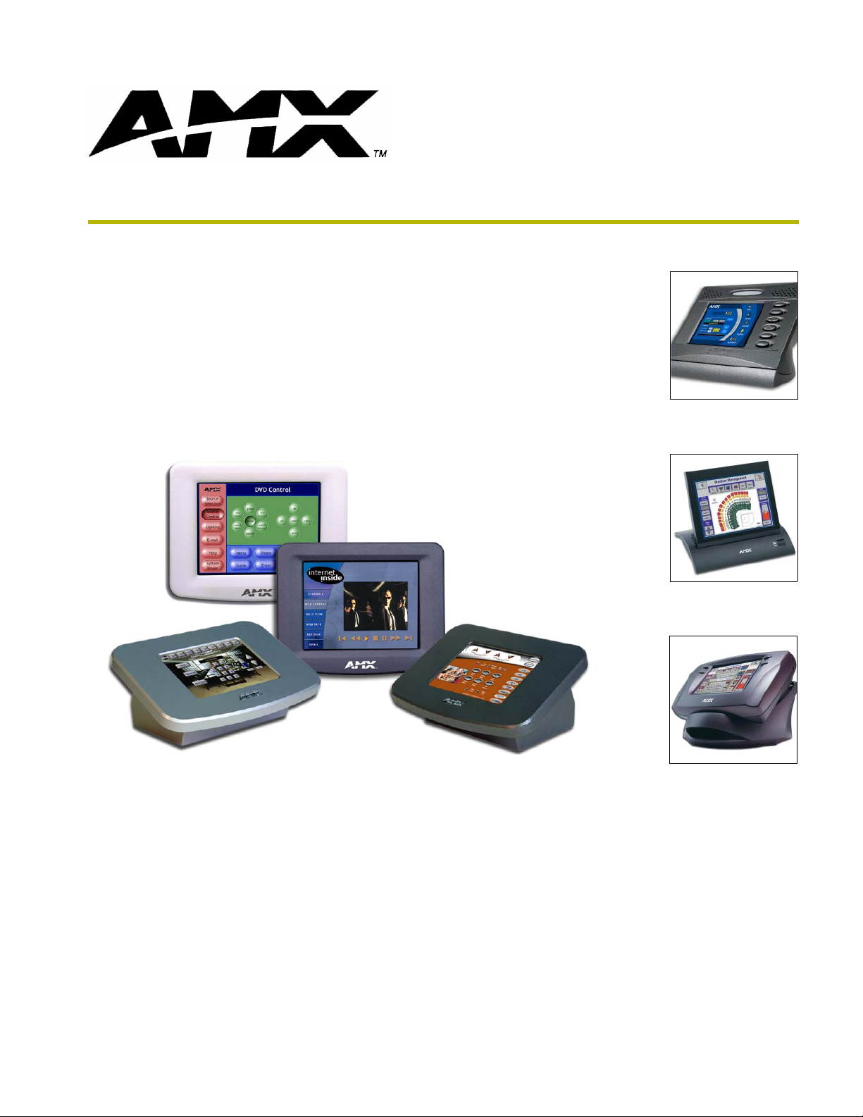
To u c h Panels and Accessorie s
Page 2

AMX Limited Warranty and Disclaimer
AMX Corporation warrants its products to be free of defects in material and workmanship under normal use for three
(3) years from the date of purchase from AMX Corporation, with the following exceptions:
• Electroluminescent and LCD Control Panels are warranted for three (3) years, except for the display and touch
overlay components that are warranted for a period of one (1) year.
• Disk drive mechanisms, pan/tilt heads, power supplies, and MX Series products are warranted for a period of one
(1) year.
• AMX Lighting products are guaranteed to switch on and off any load that is properly connected to our lighting
products, as long as the AMX Lighting products are under warranty. AMX Corporation does guarantee the
control of dimmable loads that are properly connected to our lighting products. The dimming performance or
quality cannot be guaranteed due to the random combinations of dimmers, lamps and ballasts or transformers.
• Unless otherwise specified, OEM and custom products are warranted for a period of one (1) year.
• AMX Software is warranted for a period of ninety (90) days.
• Batteries and incandescent lamps are not covered under the warranty.
This warranty extends only to products purchased directly from AMX Corporation or an Authorized AMX Dealer.
All products returned to AMX require a Return Material Authorization (RMA) number. The RMA number is
obtained from the AMX RMA Department. The RMA number must be clearly marked on the outside of each box.
The RMA is valid for a 30-day period. After the 30-day period the RMA will be cancelled. Any shipments received
not consistent with the RMA, or after the RMA is cancelled, will be refused. AMX is not responsible for products
returned without a valid RMA number.
AMX Corporation is not liable for any damages caused by its products or for the failure of its products to perform.
This includes any lost profits, lost savings, incidental damages, or consequential damages. AMX Corporation is not
liable for any claim made by a third party or by an AMX Dealer for a third party.
This limitation of liability applies whether damages are sought, or a claim is made, under this warranty or as a tort
claim (including negligence and strict product liability), a contract claim, or any other claim. This limitation of
liability cannot be waived or amended by any person. This limitation of liability will be effective even if AMX
Corporation or an authorized representative of AMX Corporation has been advised of the possibility of any such
damages. This limitation of liability, however, will not apply to claims for personal injury.
Some states do not allow a limitation of how long an implied warranty last. Some states do not allow the limitation or
exclusion of incidental or consequential damages for consumer products. In such states, the limitation or exclusion of
the Limited Warranty may not apply. This Limited Warranty gives the owner specific legal rights. The owner may
also have other rights that vary from state to state. The owner is advised to consult applicable state laws for full
determination of rights.
EXCEPT AS EXPRESSLY SET FORTH IN THIS WARRANTY, AMX CORPORATION MAKES NO
OTHER WARRANTIES, EXPRESSED OR IMPLIED, INCLUDING ANY IMPLIED WARRANTIES OF
MERCHANTABILITY OR FITNESS FOR A PARTICULAR PURPOSE. AMX CORPORATION
EXPRESSLY DISCLAIMS ALL WARRANTIES NOT STATED IN THIS LIMITED WARRANTY. ANY
IMPLIED WARRANTIES THAT MAY BE IMPOSED BY LAW ARE LIMITED TO THE TERMS OF THIS
LIMITED WARRANTY.
Page 3

Table of Contents
Table of Contents
Product Information .................................................................................................1
Specifications .................................................................................................................... 1
Cleaning the Touch Overlay.............................................................................................. 4
Installation .................................................................................................................5
Installation of the Conduit Box........................................................................................... 5
Installation of the AXD Panels........................................................................................... 6
Installing the AXD panel into a Conduit Box (CB-CV6)............................................................ 6
Installing the AXD into a flat or solid surface............................................................................ 8
Installing the AXD panel using Expansion clips (dry wall)...................................................... 10
Setup of the AC-CV6T Tabletop Enclosure..................................................................... 13
Installing the Wall Mount panel into a Tabletop Enclosure (AC-CV6T).................................. 13
Wiring the Touch Panel ................................................................................................... 16
Preparing captive wires .......................................................................................................... 16
Wiring guidelines.................................................................................................................... 17
Using the 4-pin AXlink connector for data and power ............................................................ 17
Using the 4-pin AXlink for data with external power supply ................................................... 18
Using a BNC video cable to provide video input .................................................................... 19
Using the (DB-9) RS-232 connector for mouse control or data ............................................. 19
Designing Touch Panel Pages ..............................................................................21
Buttons ............................................................................................................................ 21
Activating Edit Mode........................................................................................................ 22
Setting the Device Base .................................................................................................. 24
Setting the Device Used.................................................................................................. 24
Adding a Page................................................................................................................. 24
Setting the page color ............................................................................................................ 24
Adding a Button............................................................................................................... 24
Resizing a button ................................................................................................................... 24
Defining On-Screen and External Button Properties....................................................... 25
Setting the channel code........................................................................................................ 25
Setting the variable text code................................................................................................. 26
Setting the page flip ............................................................................................................... 26
Setting the button colors for channel-off conditions ............................................................... 26
Adding text, icons, and bitmaps to a button ........................................................................... 26
6” Color Video Touch Panels
i
Page 4

Table of Contents
Using TPDesign3 to Download Bitmaps, Icons, and Fonts............................................. 27
Creating a Bargraph and Joystick................................................................................... 27
Adding a bargraph or joystick button\..................................................................................... 28
Setting Bargraph and Joystick Properties....................................................................... 28
Setting the level code............................................................................................................. 28
Programming ..........................................................................................................29
Serial Commands............................................................................................................ 29
System Send_Commands .............................................................................................. 31
Video Send_Commands ................................................................................................. 37
Programming Numbers ................................................................................................... 39
Shorthand Send_Commands.......................................................................................... 40
Color Send_Commands.................................................................................................. 44
Variable Text Send_Commands ..................................................................................... 46
Shorthand Variable Text Commands .............................................................................. 48
Button String Commands................................................................................................ 51
Upgrading the Firmware ........................................................................................55
Configuration................................................................................................................... 55
Downloading the Firmware ............................................................................................. 55
Replacing the Battery ............................................................................................57
AC-CV6T Enclosure Battery Replacement ..................................................................... 57
AXD-CV6 Battery Replacement ...................................................................................... 58
ii
6” Color Video Touch Panels
Page 5
Product Information
The AMX Color Video Panels (CV6) contain a 6" (14.40 cm visible area) 256-color
active-matrix liquid crystal display (LCD) placed in either a Wall Mount or Tabletop enclosure
(AC-CV6T). This self-contained system uses a microprocessor to control a wide range of
multimedia equipment. The TPDesign3 touch panel design program makes it possible to create
custom pages with buttons, icons, sliders, bargraphs, time displays, logos, and drawings.
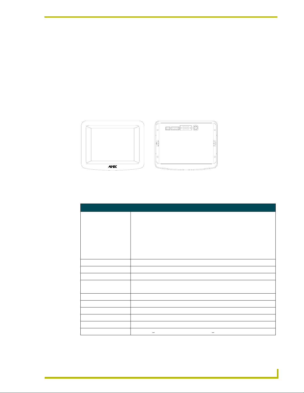
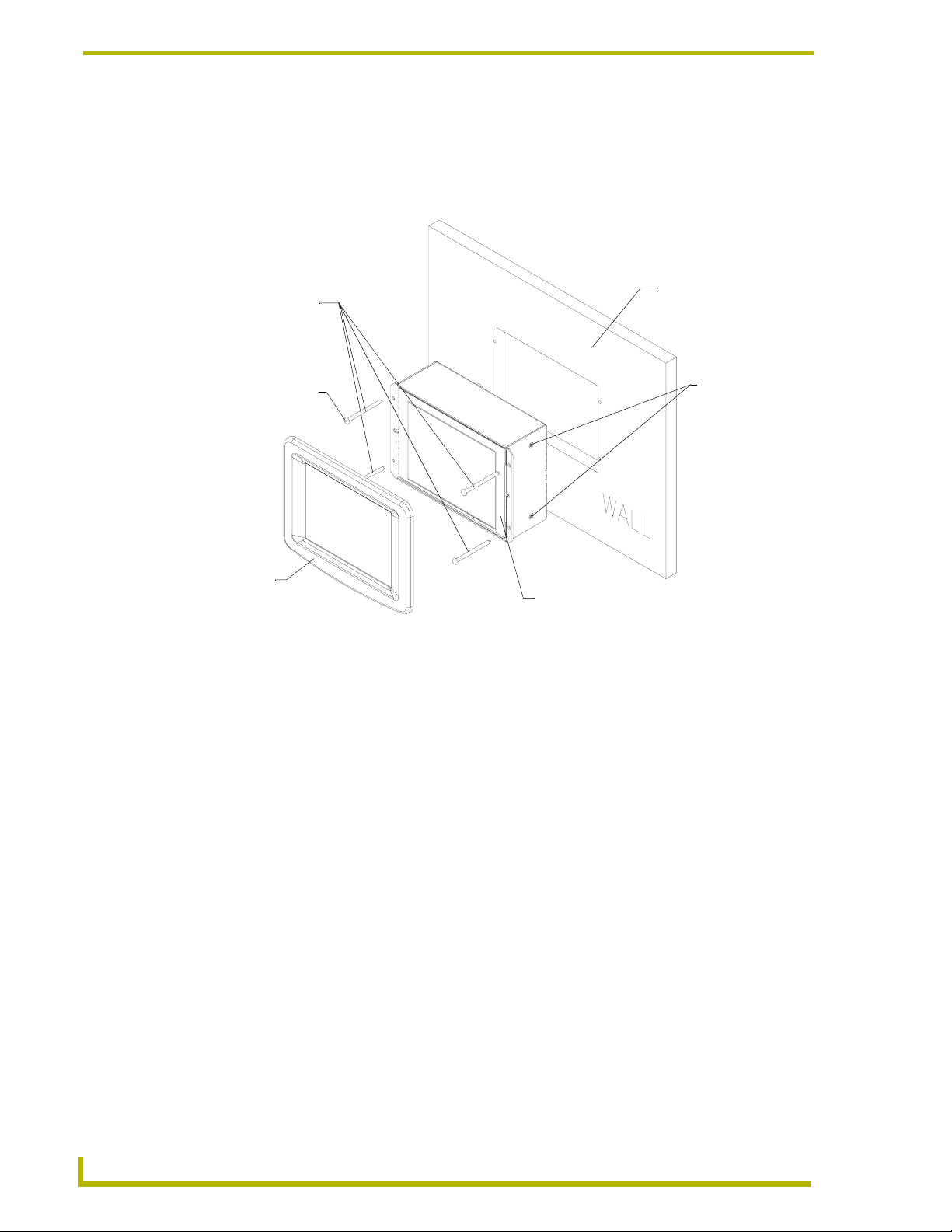
The AXD-CV6 (CV6) is designed for wall mounting with a detachable bezel and the use of an
optional CB-CV6 conduit/wall box for pre-installed surfaces. FIG. 1 shows the 6" Color Video
Wall Panel.
Product Information
Front view Rear view
FIG. 1 Wall Mount Color Video Wall Panel views (AXD-CV6)
Specifications
Specifications AXD-CV6
Dimensions (HWD):
AXT-CV6 • Faceplate: 5.37" x 6.79" x 0.30" (13.64 cm x 17.25 cm x 0.76 cm)
• CB-CV6 Conduit/Wallbox with connectors: 4.37" x 5.91" x 2.45" (11.09 cm x
15.01 cm x 6.22 cm)
• CB-CV6 Conduit/wallbox (without connections): 4.37" x 5.91" x 2.09" (11.09 cm
x 15.01 cm x 5.31 cm)
• Without connections indicates the depth of the wallbox if the protruding
connectors were not considered in the dimensions.
Weight: • 7.74 lbs. (3.51 kg)
Power Consumption: • 610 mA @ 12 VDC
Screen Resolution (HV): • 320 x 240 pixels SVGA format
Video Monitor: • 6-inch (15.24 cm) color active-matrix LCD screen
• Display size: 5.70" - 14.50 cm
Video In: • BNC male cable (NTSC/PAL/SECAM)
Dot Pixel Pitch: • 0.36 mm
Display Colors: 256K
Brightness: 350 cd/md
Contrast Ratio: 300:1
Viewing Angle: Horizontal: +
2
130° (from center) and Vertical: +105° (from center)
6" Color Video Touch Panels
1
Page 6
Product Information
Specifications AXD-CV6 (Cont.)
Memory: • 512 KB of SRAM and 2 MB of Flash for a total memory of 2.5 MB.
The following is a detailed explanation of the on-board memory parameters:
• Graphics Buffer Memory:
- SGRAM
- 1 Mbit x 32 ==> 4 MByte
- Non-user accessible
- Volatile
• Flash Memory:
- CMOS Flash
- 16 MBit x 8 ==> 2 MByte
- Partially user accessible
- Non-volatile
Note: ~400 kByte is used by the firmware and is accessible only to the
firmware during both normal operation and firmware downloads.
Note: ~1600 kByte is used by the user program and is used by TPD3
designs for bitmaps, icons, and fonts. This can be cleared using either the
external "ZAP!" command or the on-panel Factory Reset button.
• RAM:
- SRAM
- 256 kByte x 16 ==> 512 kByte
- Partially user accessible
- Non-volatile via the battery backup (volatile when batteries are removed)
Note: 256 kByte is used by firmware and is accessible only to the firmware
during normal operation.
Note: 256 kByte is used by the user program and is used by TPD3 designs
for buttons, pages, and everything else not listed in the above Flash parameter. This can be cleared using the external "ZAP!" command or
on-panel Factory Reset button.
• Component Video Buffer Memory:
- DRAM
- 256 kByte x 16 ==> 512 kByte
- Non-user accessible
- Volatile
•Clock Chip:
- RAM
- 31 Byte
- Non-user accessible
- Non-volatile via the battery backup (volatile when batteries removed)
- 31 bytes are used by the firmware to store AMX configuration information.
Note: If the battery is removed to clear the memory, it wipes out the AMX
configuration information.
• EPLD:
- EEPROM
- 32 Macrocells
- Non-user accessible
- Non-volatile
- Used by hardware for board logic (unable to clear or update)
2
6" Color Video Touch Panels
Page 7
Product Information
Specifications AXD-CV6 (Cont.)
Rear Connectors:
AXlink 4-pin bus connector for connection to the AMX Central Controller.
PWR +
RS-232 DB-9 male connector for data transmission or Microsoft
Video BNC female connector (NTSC/PAL/SECAM)
Character Support: Unicode
Compatibility: Axcess, NetLinx, and Landmark systems (AXlink is the most common control stan-
Operating
Environment:
Installation Kit: • 4-pin AXlink data/power connector
Enclosure: • Metal sub-plate and bezel with black or white matte finish
Installation Cutout: Cutout Template for the AXD-CV6 is available as drawing number 62-5924-06 and
Optional
Accessories:
12 VDC power supply; power is supplied through the bus or an external PSN power
supply.
®
mouse control
®
character support for far-eastern languages such as Chinese.
• Characters for middle-eastern languages such as Arabic are not supported within
the Unicode fonts because they are bi-directional. Buttons with Unicode fonts can
only be created and edited using TPDesign3 and NetLinx Studio. Refer to the
respective manuals for additional information.
dard for this system).
Indoor operation at temperatures between 0
humidity range of 5% to 90% RH (non-condensing).
• 2-pin PWR connector
• Drywall clip set (2-drywall clamps and 2- #8 (2" long) screws)
• 4-#4-40 machine screws and threaded inserts
• Detachable magnetic front panel bezel
inserted in the product packaging.
This file provides 1:1 cutout dimensions for the CV6 conduit/wallbox. For
replacement of the cutout, contact your AMX sales representative.
• AC-CV6T Accessory Tabletop (used to mount an AXD panel onto a tabletop
surface
• CB-CV6 Conduit/wallbox (includes flanges for installation to studs during the
construction phase). Conduit/Wallbox should only be mounted to a beam
before a drywall is installed (pre-wall).
• Optional spacers and bezels for international sales
• PSN2.8 Power supply (can be used to power the CV6)
• PSN6.5 Power supply (recommended to power the CV6)
º C (32º F) to 50º C (122º F) and a
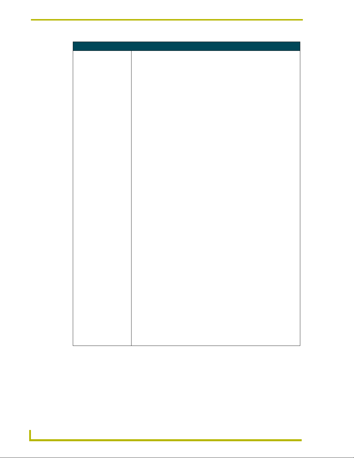
The CV6T is designed to be used on any flat/level surface. The AC-CV6T (FIG. 2) is a metallic
tabletop enclosure that encases the CV6 touch panel and allows its use on a wide variety of
horizontal surfaces.
FIG. 2 AC-CV6T Tabletop Enclosure views (CV6 unit within an AC-CV6T enclosure)
6" Color Video Touch Panels
Front view
Mounting blocks (2)
Rear view
Strain relief/cable
insertion location
3
Page 8
Product Information
Finishing Instructions for Aluminum AC-CV6T (FG5924-22).
Surface preparation for the Aluminum CV6T is very important.
The unfinished aluminum version of the AC-CV6T is supplied with a sanded,
non-coated aluminum bezel, aluminum panel mounting blocks, and a stainless
steel base enclosure. Please consult a qualified painter for the appropriate
surface treatment compatible with the end users desired topcoat.
Specifications AC-CV6T Enclosure
Dimensions (HWD):
V6T
AC-C
(FG5924-20/21/22)
Weight:
Enclosure with
AXD-CV6
Enclosure only
Enclosure: • Metal enclosure and removable front panel bezel (with matching colors):
Rear Connectors:
Compatibility: • AXD-CV6 White Video Touch Panel (FG5924-10)
Included Accessories: • 2 Mounting blocks (attach the bezel to the base)
• Faceplate: 6.47" x 8.69" x 0.60" (16.43 cm x 22.07 cm x 1.52 cm)
• Base Enclosure: 3.84" x 6.50" x 4.45" (9.75 cm x 16.51 cm x 11.30 cm)
• 11.49 lbs. (5.21 kg)
• 3.75 lbs. (1.70 kg)
• Dark Grey matte finish (FG5924-20)
• Platinum matte finish (FG5924-21)
• Unfinished Aluminum (FG5924-22) Aluminum version of enclosure is
unpainted so as to provide easier preparation for custom painting options.
• All cable connectors are routed out from the enclosure via a hole located on the
rear of the unit
• Internal connections are made to the AXD-CV6 rear connectors via an AC-CV6T
tabletop cable.
• AXD-CV6 Black Video Touch Panel (FG5924-11)
• 4 Mounting screws
• 10’ (3.05 meters) AC-CV6T Tabletop cable (Video/AXlink cable combo)
(64-5924-01). Uses BNC and mini-Phoenix AXlink connectors
• 1 BNC connector (41-1077) (for use in terminating the Red mini-coax cable)
• 1 black strain relief (secures tabletop cable to enclosure) (45-0004-02)
Cleaning the Touch Overlay
You should clean the touch screen overlay often. Always use clean cotton cloths, and a spray bottle
of cleaning solution consisting of 50% isopropyl alcohol and 50% water.
4
6" Color Video Touch Panels
Page 9
Installation
Installation of the Conduit Box
Wall Mount panels (AXDs) are contained within a metallic outer housing (back box). This back
box is not removed when installing the AXD into a conduit box (CB-CV6).
INSTALLER: LEAVE A GAP BETWEEN THE STUD AND CONDUIT BOX TO
ACCOMMODATE THE DRYWALL SHEETROCK. This gap allows the installation of
the drywall/sheetrock after the conduit box has been installed.
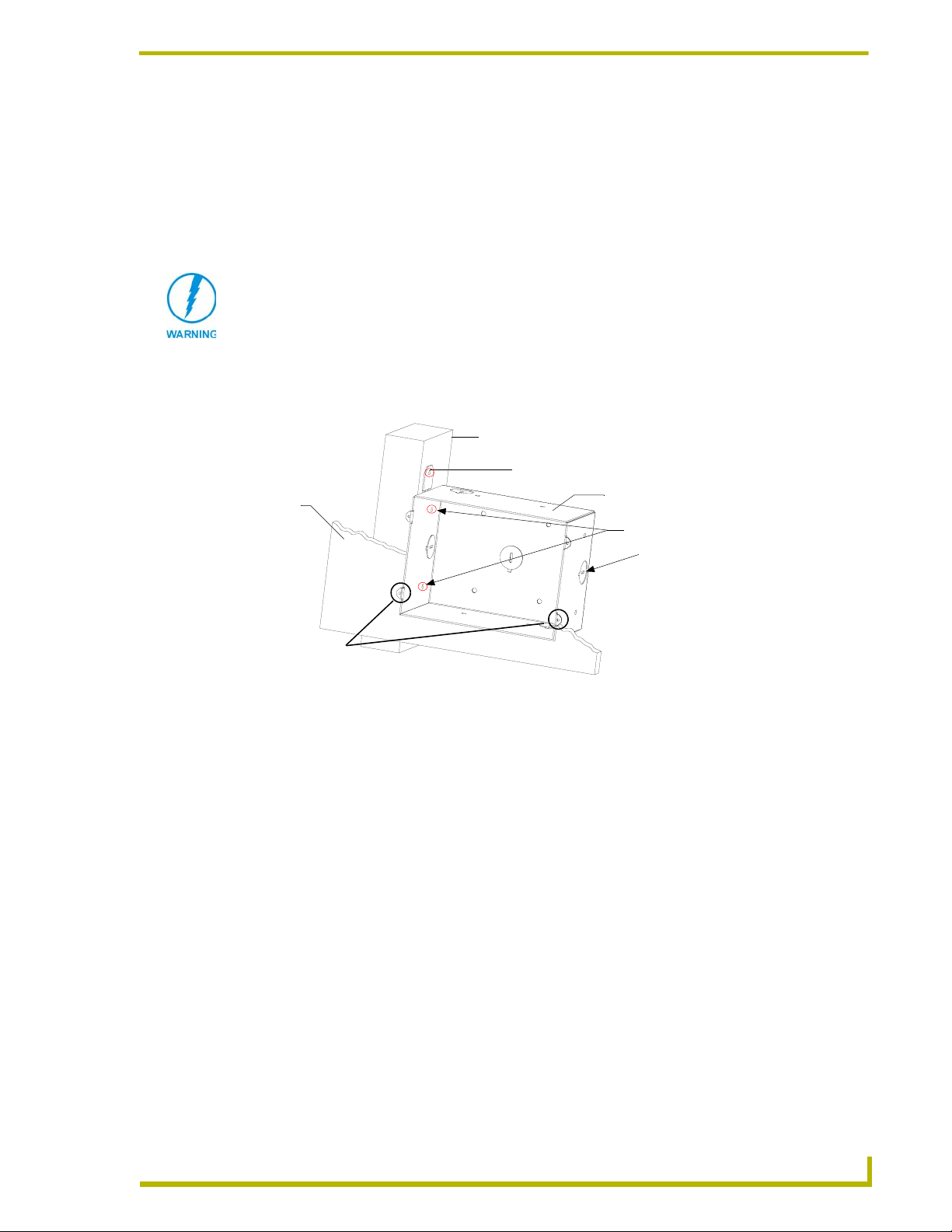
1. Fasten the CB-CV6 to the stud through the tabs shown in FIG. 3. The wallbox can be secured
to the stud by using either nails or screws. This installation must be done prior to any wall
installation.
Installation
Stud
Tabs may be removed if not used for the installation
Sheet
rock
Mounting tabs
for AXD panel should
be flush with the outside of the sheetrock
FIG. 3 Screw location for CB-CV6 conduit box attachment in a pre-wall installation
CB-CV6 Conduit Wallbox
Stud fastening holes
Knockouts
TYPICAL DRYWALL INSTALLATION
2. Remove any necessary wiring knockouts from the (optional) conduit box where the necessary
cables are threaded through for connection to the touch panel.
3. Thread the incoming wiring through the knockouts. Leave enough slack in the wiring to
accommodate any re-positioning of the panel.
4. Install the drywall/sheetrock before inserting the main AXD unit into the CB-CV6.
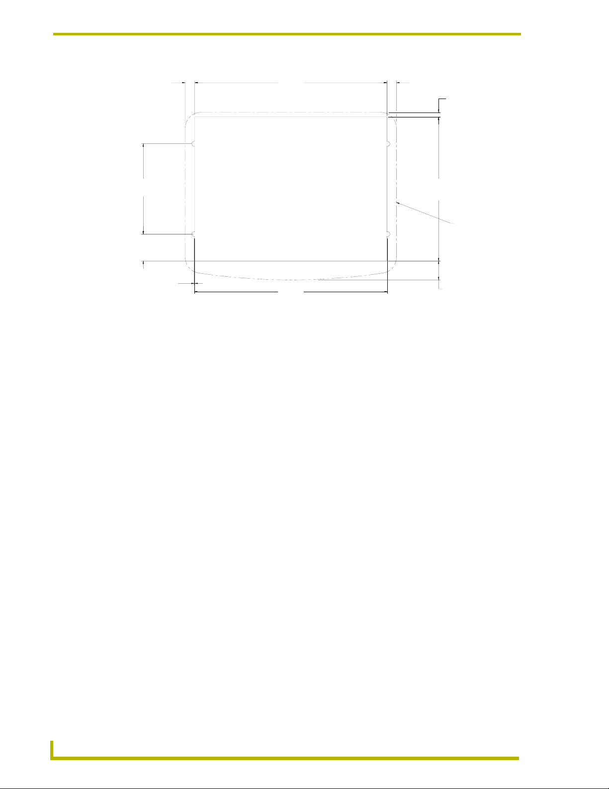
If installing the CB-CV6 into an pre-existing wall or surface, use the following cutout
information (FIG. 4
) (found online at www.amx.com using drawing number SP5924-02).
6" Color Video Touch Panels
5
Page 10
Installation
.308
7.8MM
6.174
156.8MM
NOTICE:
THIS CUTOUT IS INTENDED FOR
MOUNTING THE CB-CV6 CONDUIT
2.900
73.7MM
.862
21.9MM
.018
0.5MM
CUTOUT SHOWN FOR CONDUIT WALLBOX WITH TABS REMOVED
FIG. 4 Cutout information for CB-CV6 (used with pre-existing surfaces)
WALLBOX ONLY. IF INSTALLING AXD-CV6
WITHOUT CONDUIT WALLBOX USE THE
MOUNTING TEMPLATE SUPPLIED WITH
AXD-CV6, OR REFER TO AMX MOUNTING
SPECIFICATION SP9524-01
6.210
157.7MM
RECOMMENDED CUTOUT
Installation of the AXD Panels
.309
7.8MM
4.624
117.5MM
15.4MM
.144
3.7MM
AXD-CV6
BEZEL OUTLINE
.606
The following paragraphs describe installing the Wall Mount touch panel using the different types
of available methods and surfaces. The AXD panel can be installed either directly into the
(optional) CB-CV6 or other solid surface environment using the two different mounting options:
drywall clips or solid surface screws. The following sections describe mounting the touch panel
directly into a pre-wall installed conduit box, a solid surface or drywall, and optional Rack Mount
Kit.
Installing the AXD panel into a Conduit Box (CB-CV6)
The CB-CV6 Conduit/wallbox is an optional metallic housing that is installed onto a beam in a
pre-wall setting. The CV6 is housed in a plastic backbox that ships with the unit. Verify that all
necessary cables have been threaded through the knockouts on the conduit box and the connections
have been tested prior to installation of the AXD panel. To install Wall Mount touch panels into a
conduit/wallbox pre-mounted within a solid surface:
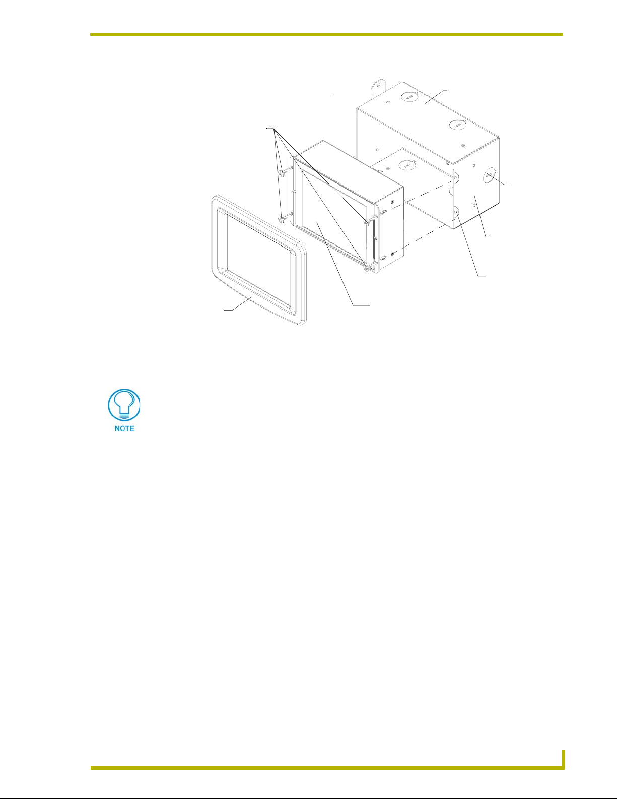
1. Remove the magnetically attached faceplate (A in FIG. 5) from the main AXD unit
(B in FIG. 5) by gripping the faceplate and pulling with gentle force.
2. Remove any necessary wiring cutouts from the pre-installed (optional) conduit box
(C in FIG. 5) (CB-CV6) where the AXlink cable is threaded through for connection to the
touch panel (FIG. 5). The snaps located along the side of the conduit/wallbox can be snapped
off or used to mount the unit to a hard surface (like a wooden support beam).
3. Verify the incoming cables have been properly threaded through the wiring knockouts (from
their terminal locations) on the conduit box. Leave enough slack in the wiring to accommodate
any re-positioning of the panel.
4. Connect all data and power wiring connectors to their corresponding locations along the rear of
the (un-powered) AXD touch panel.
6
6" Color Video Touch Panels
Page 11
Installation
Removable
tabs used to
mount the box
Install the (2) #4-40
screws into the places
- Decor
A
faceplate
FIG. 5 Wall Mount panel installation configuration for pre-existing conduit/wall box
Verify the terminal end of the power cable is not connected to a power supply before
indicated
to a stud beam
B - Main AXD unit consists of
the touch panel and backbox housing
C - Optional CB-CV6
conduit/wallbox
plugging in the 2-pin power connector.
Cable
knockouts
Installed flush
against a solid
surface
Do not use these
Mounting tabs to
mount the
conduit /wallbox
Don’t disconnect the connectors from the touch panel. The unit must be installed with
the attached connectors before being inserted into the conduit box.
5. Test the incoming wiring by connecting the panel connections to their terminal locations and
applying power. Verify the panel is receiving power and functioning properly to prevent
repetition of the installation.
6. Disconnect the terminal end of the power cable from the connected power supply.
7. Carefully slide the main unit (B in FIG. 5) into the conduit box, so the Mounting Tabs lie flush
against the conduit box (C in FIG. 5).
8. Insert and secure the four securing #4-40 Mounting Screws into their corresponding holes
located along the sides of the AXD(FIG. 5).
9. Replace the magnetic faceplate (A in FIG. 5) on the main AXD touch panel unit. Make sure
the faceplate is flush against the housing and it is secure.
10. Reconnect the terminal connectors wiring to their respective locations (outside the conduit
box).
11. Reconnect the terminal power connector on the PS power supply and apply power. The touch
panel beeps when power is applied.
6" Color Video Touch Panels
7
Page 12
Installation
Installing the AXD into a flat or solid surface
To install AXD-CV6 touch panels:
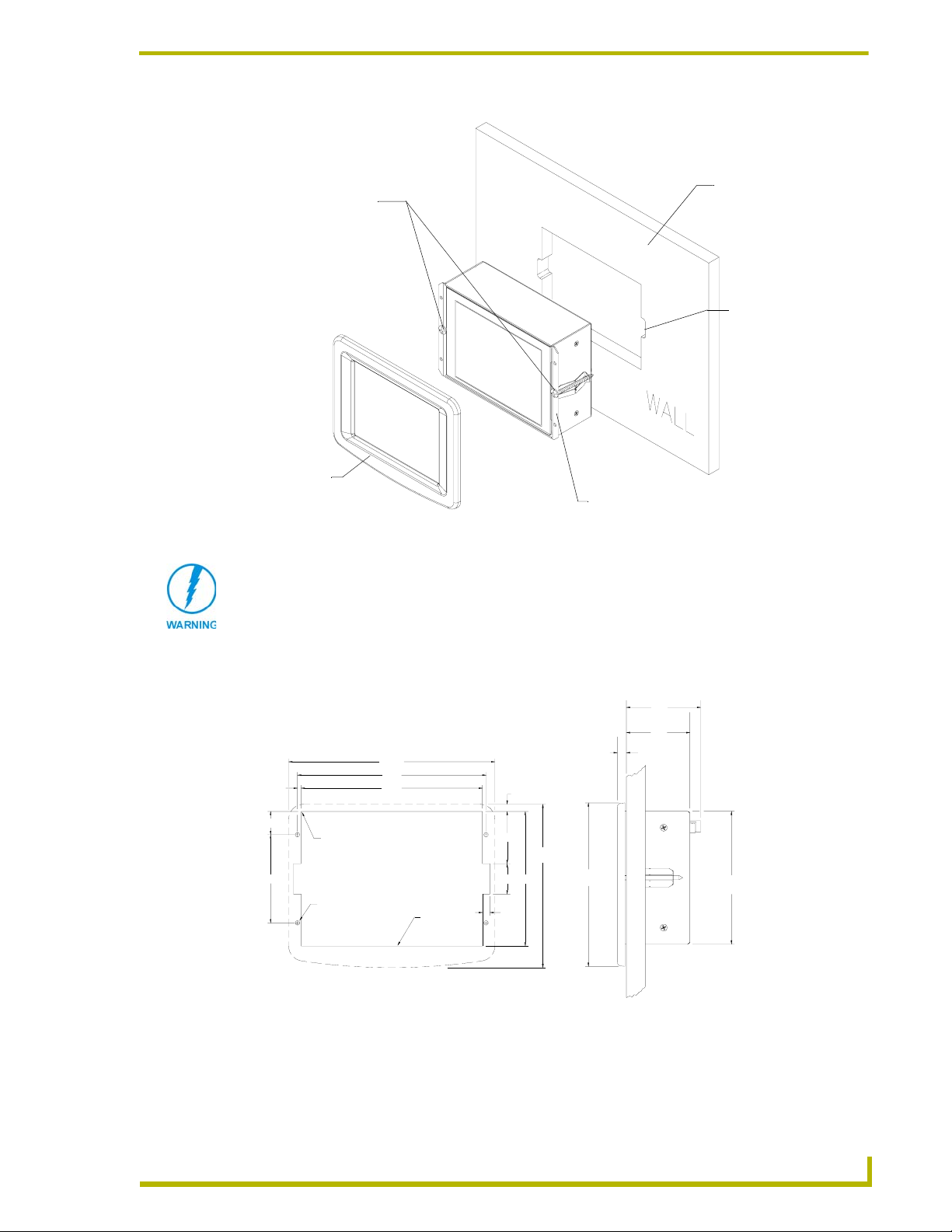
1. Remove the magnetically attached Decor faceplate (A in FIG. 6) from the main AXD unit
(B in FIG. 6) by gripping the faceplate and pulling with gentle force.
Solid surface
Install the #4-40
machine screws
into the holes
shown below.
Screw length
depends on the
installation surface.
(can include a
wall, podium, or
other level
surface)
These 4 screws
are removed
to access or
replace the
battery.
A
- Decor
faceplate
FIG. 6 Wall Mount panel installation configuration for flat /solid surfaces
B - Main AXD unit consists of
the touch panel and housing
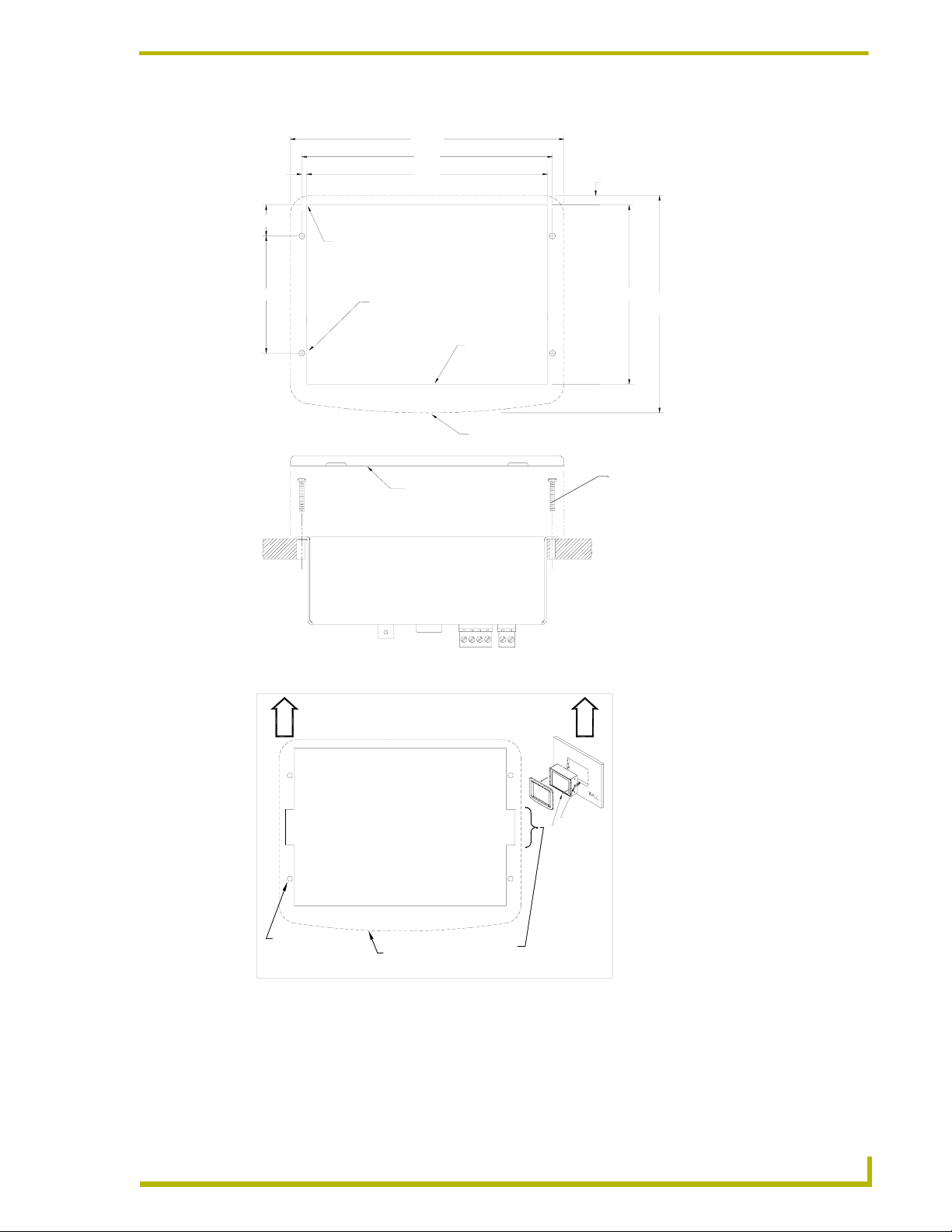
2. Cut out the surface using the dimensions shown in FIG. 7. Be sure not to cut out notches for the
expansion clips (only used when mounting the panel in plasterboard). FIG. 8 shows a sample
of the CV6 (62-5924-06) cutout template used for an accurate visual reference of the cutout
dimensions.
3. Thread the incoming AXlink wiring through the cutout on the flat surface.
4. Disconnect the AXlink connector from the Central Controller and thread the terminal end of
the 4-pin AXlink cable through the circular cable knockouts provided on the wallbox.
5. Attach the data and power wiring to the touch panel.
6. Test the connection by reconnecting the AXlink connector to the Central Controller. Verify that
the panel is receiving power and functioning properly to prevent repetition of the installation.
7. Disconnect the AXlink connector from the Central Controller until installation is complete.
8. Connect the data and power wiring to the rear of the touch panel.
9. Insert the main unit into the flat surface mounting until firmly positioned and flush with the
surface battery.
10. Fasten the main AXD unit to the surface using the four surface-screws (#4 screws) supplied
with the enclosure (FIG. 9).
11. Place the magnetic Decor faceplate (A in FIG. 9) onto the main AXD unit (B in FIG. 9) by
gripping the faceplate and placing it on with gentle force.
8
6" Color Video Touch Panels
Page 13
.
2.900
Installation
6.79
(BEZEL)
6.21
.12
6
7
ZERO RADIUS REQUIRED
IN THESE 4 CORNERS.
5.97
THESE 4 HOLES ARE ONLY REQUIRED
WHEN MOUNTING UNIT TO A SOLID
SURFACE (PODIUM, DESK, ETC.).
SECURE UNIT WITH #4 SCREWS.
SUGGEST INSTALLATION OF #4-40
THREADED INSERTS AT THESE 4
LOCATIONS.
CUTOUT
FRONT BEZEL
.28 REF
4.43
5.37
(BEZEL)
#4-40 machine screw inserts (#4 screws)
FRONT BEZEL
used for mounting to a flat surface (provided
by installer)
FIG. 7 Wall Mount panel cutout dimensions for flat surface mounting
U
P
CUT-OUT TEMPLATE
(NOT FOR USE WITH BB-CV6 CONDUIT BOX)
AXD-CV6
U
P
If something happens
to the template, contact
your sales representative
for another copy.
THESE 4 HOLES ARE REQUIRED
ONLY WHEN MOUNTING UNIT TO A
SOLID SURFACE (PODIUM, DESK, ETC.).
SECURE UNIT WITH #4 SCREWS.
SUGGEST INSTALLATION OF #4-40
THREADED INSERTS AT THESE 4
LOCATIONS.
FRONT BEZEL
THESE 2 NOTCHES ARE REQUIRED
ONLY IF UNIT IS INSTALLED USING
DRYWALL EXPANSIONS CLIPS
(2 PROVIDED)
DRYWALL CLIPS (2)
2" LONG SCREWS (2)
NOTE ORIENTATION REAR CONNECTORS
TOWARDS TOP
FIG. 8 Sample router cutout dimension template for the CV6
12. Reconnect the AXlink wiring to the Central Controller. The touch panel beeps when power is
applied.
6" Color Video Touch Panels
9
Page 14
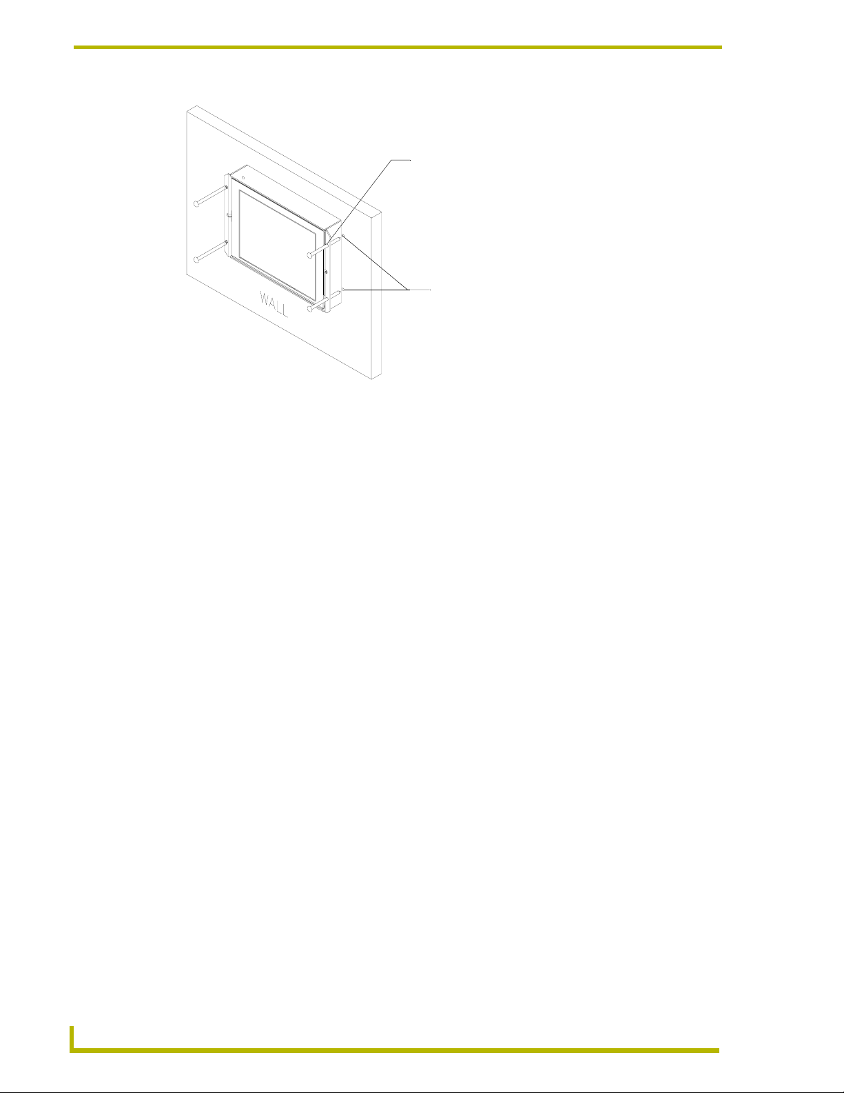
Installation
Surface mount screws
are inserted through the
outer holes along the housing.
Four drilled holes correspond
to the four (#4) screws used to
secure the housing to the flat surface.
FIG. 9 Screw locations for flat surface mounting of the main AXD unit
Installing the AXD panel using Expansion clips (dry wall)
Expansion clips are mounted through the two oval holes located at the sides of the panel. As the
screw is tightened, the clip bends toward the insertion hole and into the wall. This bending creates a
"grip" on the wall by either pressing onto the wall or by securing the drywall between the housing
and the drywall clip.
The most important thing to remember when mounting the AXD is that the outer frame
(Mounting Tabs) must be installed flush against the mounting surface.
1. Remove the magnetically attached Decor faceplate (A in FIG. 10) from the main AXD unit
(B in FIG. 10) by gripping the faceplate and pulling with gentle force.
10
6" Color Video Touch Panels
Page 15
Installation
Install the 2 drywall
clips and screws
(included) into the
holes
A
- Decor
faceplate
B - Main AXD unit consists of
the touch panel and housing
FIG. 10 Wall Mount panel installation configuration for drywall surfaces
The drywall clip set must be re-ordered from AMX if the drywall clip is bent
accidentally during an installation or removed during a re-installation.
Flat surface
(can include a
wall, podium, or
other level
surface)
2 notches are
required if the unit
is installed in
drywall using the (2)
provided clips
2. Cut out the install surface using the dimensions shown in FIG. 11. Be sure to cut out the two
notches along the side of the CV6 to accommodate the two provided drywall expansion clips.
2.45
[62.2 MM]
2.09
[53.1 MM]
.30
[7.6 MM]
MAX
WALL
4.37
[110.9 MM]
2.900
Front view Side view
6.79
(BEZEL)
.12
6
.
7
ZERO RADIUS
TYP. ALL CORNERS.
.140 DIA HOLES
(CUTOUT)
6.21
5.97
CUTOUT
1.71
1.00
.25 TYP
.28 REF
5.37
(BEZEL)
4.43
5.37
[136.5 MM]
FIG. 11 Wall Mount panel installation configuration for plasterboard
3. Thread the incoming AXlink wiring through the cutout in the wall.
4. Disconnect the AXlink connector from the Central Controller and thread the terminal end of
the 4-pin AXlink cable through the circular cutout provided on the wallbox.
6" Color Video Touch Panels
11
Page 16
Installation
5. Attach the data and power wiring to the touch panel.
6. Test the connection by reconnecting the AXlink connector to the Central Controller. Verify that
the panel is receiving power and functioning properly to prevent repetition of the installation.
7. Disconnect the AXlink connector from the Central Controller until installation is complete.
8. Connect the data and power wiring to the rear of the touch panel.
9. Insert the main unit into the wall cutout until firmly positioned and flush with the wall.
10. Fasten the main AXD unit to the surface using the two (2) drywall clip sets (consisting of
screws and clips) supplied with the enclosure (FIG. 12).
Dry wall screws
are inserted through the
center holes on the housing.
Dry wall clips and screws
are inserted through the
notches cut out in the wall.
FIG. 12 Screw and clip locations for plasterboard (dry wall) mounting of main AXD unit
11. Place the magnet faceplate (A in FIG. 10) onto the main AXD unit (B in FIG. 10) by gripping
the faceplate and placing it on with gentle force.
12. Reconnect the AXlink wiring to the Central Controller. The touch panel beeps when power is
applied.
12
6" Color Video Touch Panels
Page 17
Installation
Setup of the AC-CV6T Tabletop Enclosure
The following paragraphs describe the setup procedures for installing the Wall Mount touch panel
into a tabletop enclosure. The enclosure works by encasing an existing AXD-CV6 touch panel and
using a tabletop cable (AXlink/Video) to connect the unit to both a Master Controller and video
sources.
Finishing Instructions for Aluminum AC-CV6T (FG5924-22).
Surface preparation for the Aluminum CV6T is very important.
The unfinished aluminum version of the AC-CV6T is supplied with a sanded,
non-coated aluminum bezel, aluminum panel mounting blocks, and a stainless
steel base enclosure. Please consult a qualified painter for the appropriate
surface treatment compatible with the end users desired topcoat.
Installing the Wall Mount panel into a Tabletop Enclosure (AC-CV6T)
The CV6T enclosure is an optional metallic housing that is used to mount the base CV6 LCD touch
panel onto a horizontally flat surface. The enclosure uses a plastic strain relief to secure the tabletop
cable to the enclosure.
To install Wall Mount touch panels into an AC-CV6T enclosure:
1. Remove the coiled 10-foot (3.05 m) tabletop cable and accessory bag from within the
enclosure.
2. Confirm that all of the included accessories are present in the box. Refer to the Specifications
AC-CV6T Enclosure table on page 4 for content information.
3. Uncoil the cable and thread the non-terminated end of the tabletop cable into the base
enclosure and then out through the rear opening (FIG. 13).
Base
enclosure
FIG. 13 Threading the tabletop cable through the base enclosure
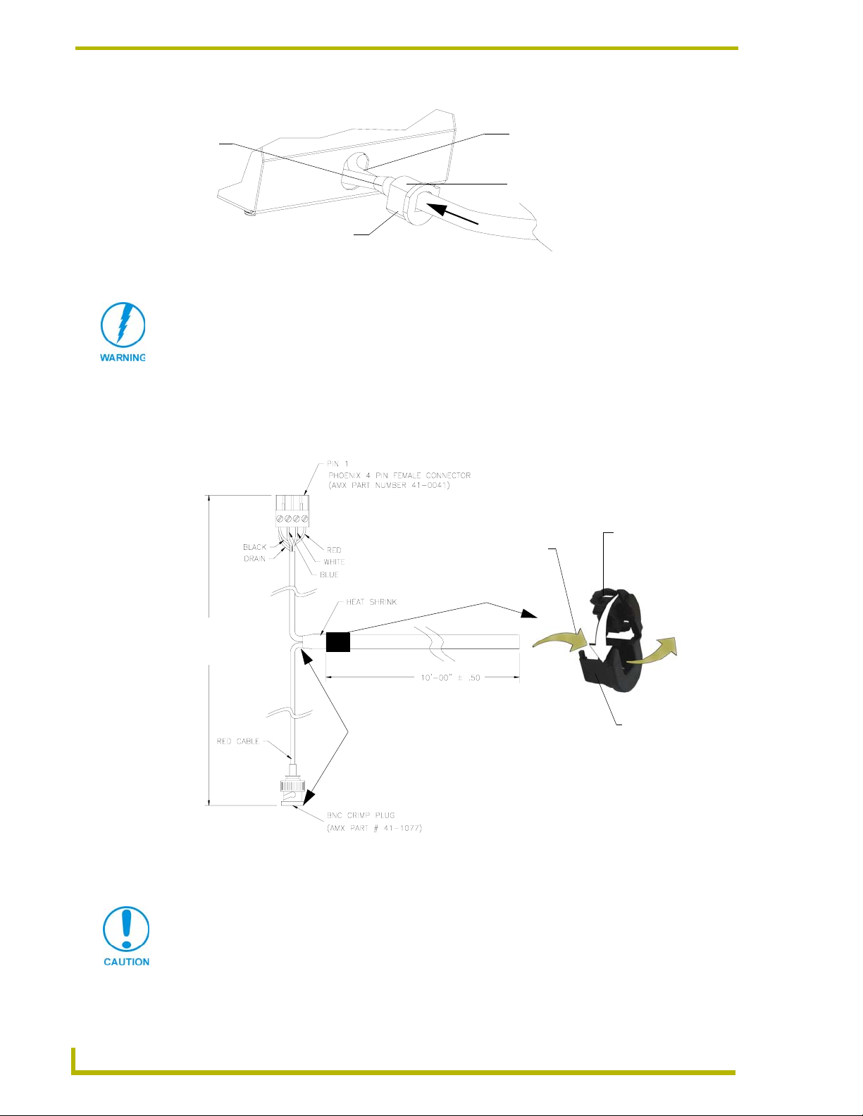
4. Continue to thread the cable through the strain relief opening until the heat shrink tubing is
located outside of the enclosure. Refer to FIG. 14 for the final position of the strain relief/cable
combo.
6" Color Video Touch Panels
13
Page 18
Installation
Rear view
Heat
shrink
Strain relief
is mounted on the
edge of the heat shrink
FIG. 14 Installation of relief/cable combo into the AC-CV6T enclosure
Circular front of strain relief
lies flush against enclosure
CLIP FACING UP
VERIFY THE DIRECTION AND LOCATION OF THE STRAIN RELIEF.
The clip must be facing UP (on top).
Once closed, it is difficult to re-open. Grooves align against heat shrink and the flat
circular opening faces away from the enclosure. Refer to FIG. 15 for more
information.
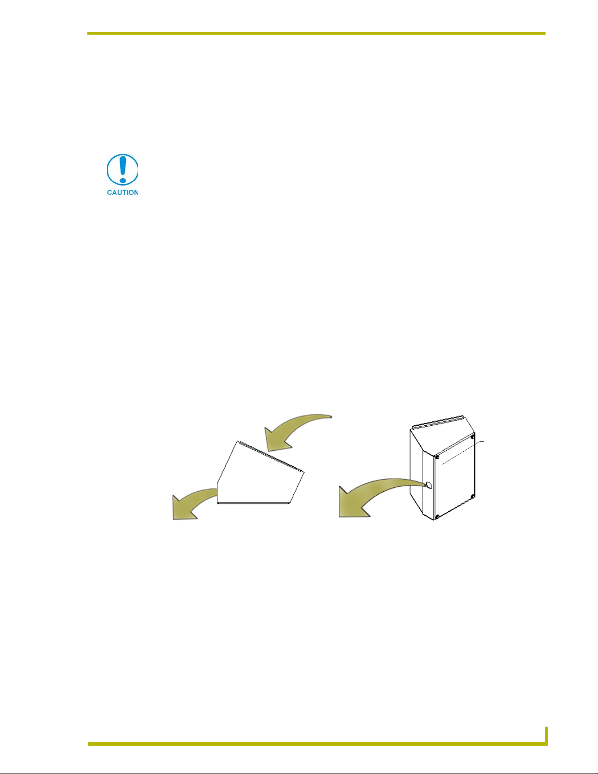
5. Position the strain relief onto the cable with the strain relief located against the heat shrink
tubing (at the base of the tabletop cable split) as shown in FIG. 15 on page 14. The strain relief
should begin clasping after the heat shrink.
Third - Snap closed
First - Thread through
10 inches
total
Strain relief
5 inches
(from tip to base)
RELIEF GROOVES GO INTO ENCLOSURE
FLAT SURFACE POINTS AWAY FROM ENCLOSURE
FIG. 15 Tabletop cable and strain relief installation
6. Close the strain relief over the designated location.
Verify the relief is securely closed over the cable and facing the correct
direction. The process of securing the strain relief might require the use of
pliers.
Second - Position
cable
14
6" Color Video Touch Panels
Page 19

Installation
7. Firmly insert the cable/strain relief combo into the base enclosure opening by pushing the
combo through the base opening (toward the inside) until the relief is securely flush against the
base. Refer to FIG. 14 on page 14 for the final position of the strain relief/cable combo.
8. Position the base enclosure onto a flat surface.
9. Grip the CV6 unit, from either sides of the enclosure, and while angling the front of the CV6
unit upwards, connect the AXlink and BNC connectors (FIG. 16) at the their respective
connector locations shown below.
2-pin PWR
connector
4-pin AXlink
connector
CV6 (Rear view)
FIG. 16 Rear views of the CV6 touch panel
BNC (female) video connector
DB-9 RS-232 connector
Verify the connectors are securely attached to the AXlink and/or BNC ports on the
rear of the CV6 unit.
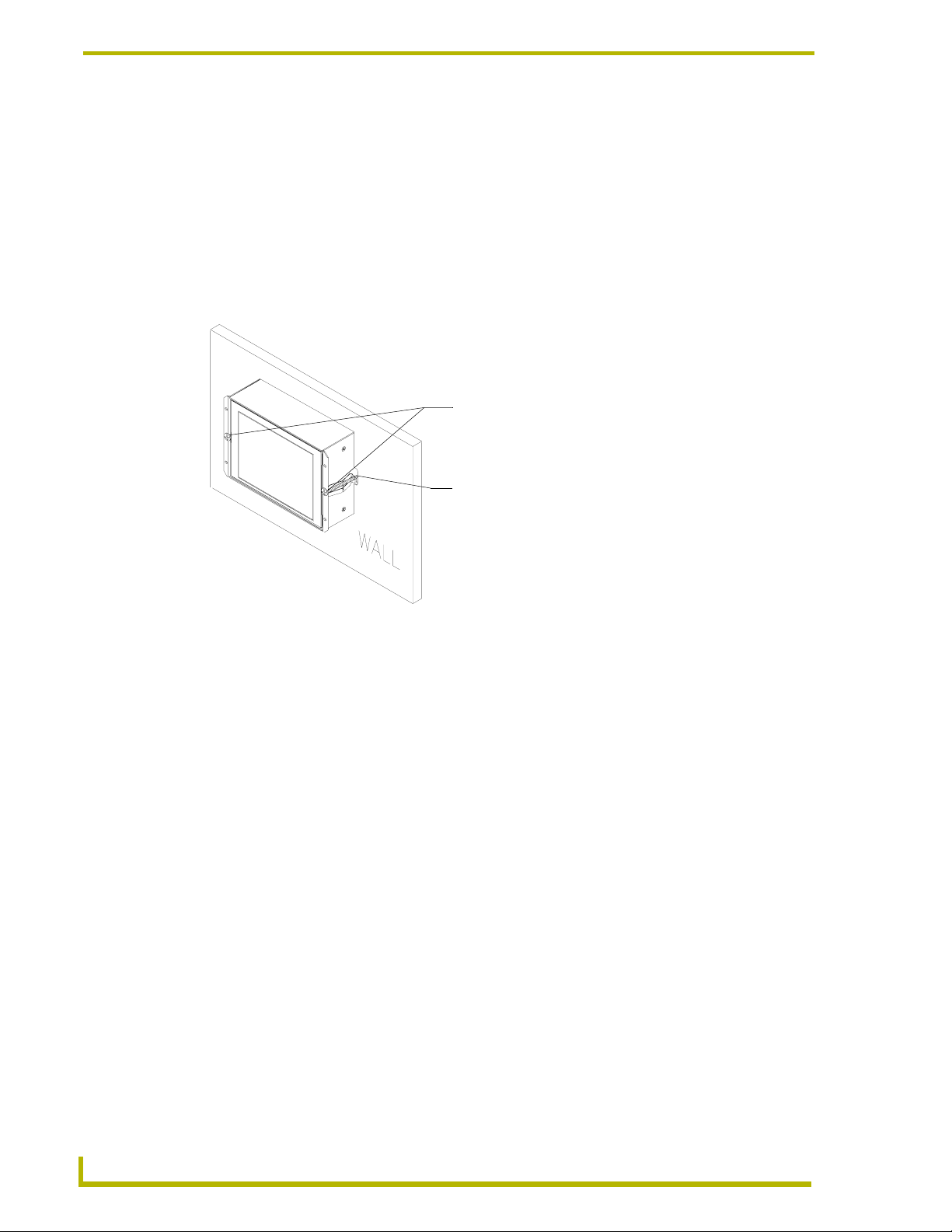
10. Carefully slide-in the connected CV6 unit (C in FIG. 17) into the base enclosure until the CV6
flanges lie flat against the base enclosure. Take care in positioning the connector wires into
the open space within the base (under the CV6 unit).
D - AC-CV6T
faceplate/bezel
CV6 flanges
A
- Base
opening
(showing
strain relief
installed
C - Main AXD-CV6
touch panel unit
4 Screws (8-32)
FIG. 17 Installation of main CV6 unit into an AC-CV6T enclosure
The following steps occur outside the base enclosure.
6" Color Video Touch Panels
B - 2 mounting blocks
secure the base to the faceplate
15
Page 20
Installation
11. Position the faceplate/bezel (D in FIG. 17) above the enclosure base.
12. Securely grab the LCD and enclosure unit combo (enclosure unit is made up of the base and
faceplate).
13. Carefully flip the combo over onto a soft cloth to prevent scratching the faceplate during the
installation of the mounting blocks.
14. Insert the mounting blocks (B in FIG. 17) into the opening below both sides of the faceplate.
The elevated groove on the blocks should lie against the base enclosure.
15. Insert two of the provided enclosure screws into each of the mounting blocks and secure the
bracket to the faceplate by turning the screws using a clockwise motion. Repeat this step for
the second mounting block.
For the unpainted (Aluminum) configuration, the AMX logo will be included in the
package (not attached).
After the custom pain and finish (refer to the caution on page 13), please attach the
self-adhesive AMX logo into the provided recess on the front of the panel and the
rubber feet at the bottom of the unit.The attachment of the AMX logo is a strict AMX
branding requirement.
If using the enclosed BNC connector (41-1077) to terminate the cable, use of a
hexagonal crimp tool (with a 0.178 opening) for installation onto the red mini-coax
cable (see FIG. 15 on page 14).
Wiring the Touch Panel
The AXD-CV6 uses a 4-pin AXlink connector for power and data.
IF NOT USING tabletop cable, the user must wire both AXlink and BNC cables for
use on both the Wall Mount and enclosed touch panels. This section indicates the
wiring procedures for configuring the two types of cables.
Use a hexagonal crimp tool (with a 0.178 opening) to crimp the BNC connector
(41-1077) onto the red mini-coax cable (see FIG. 17 on page 15) located at the
terminal end (no connectors) of the tabletop cable (64-5924-01).
If the distance between the panel and Central Controller exceeds power consumption limits, you
must connect an optional 12 VDC power supply to the 2-pin PWR connector. If the panel is
connected to an AXlink cable and receiving power from a 2-pin PWR connector, power is not sent
through the AXlink cable to any connected device.
Some installations of the AXD-CV6 may require a 90° right-angle BNC adapter to
accommodate a sharp bend in the video cable. Be careful not to crimp the video
cable and possibly damage the BNC connector by bending the video cable too far.
Preparing captive wires
You will need a wire stripper and flat-blade screwdriver to prepare and connect the captive wires.
1. Strip 0.25 inch (6.35 mm) of insulation off all wires.
2. Insert each wire into the appropriate opening on the connector (according to the wiring
diagrams and connector types described in this section).
16
3. Tighten the screws to secure the wire in the connector. Do not tighten the screws excessively;
doing so may strip the threads and damage the connector.
6" Color Video Touch Panels
Page 21

Installation
Do not connect power to the touch panel until wiring is complete. If you are using a
12 VDC power supply, apply power to the touch panel only after installation is
complete.
Wiring guidelines
The touch panel requires 12 VDC power to operate properly. The touch panel can use either a
PS(N)2.8 (if the power is being supplied only to the touch panel) or a PSN6.5 power supply (if the
power is being routed through the touch panel to power another device). The Central Controller
supplies power via the AXlink cable or external 12 VDC power supply. The maximum wiring
distance between the Central Controller and touch panel is determined by power consumption,
supplied voltage, and the wire gauge used for the cable. The table below lists wire sizes and the
maximum lengths allowable between the touch panel and Central Controller. The maximum wiring
lengths for using AXlink power are based on a minimum of 13.5 volts available at the Central
Controller’s power supply. Refer to the Specifications section on page 1 for more information.
Wiring Guidelines @ 610 mA
Wire Size Maximum Wiring Length
18 AWG 192.41 feet (58.65 m)
20 AWG 121.73 feet (37.10 m)
22 AWG 75.90 feet (23.13 m)
24 AWG 47.84 feet (14.58 m)
If you install the touch panel farther away from the Central Controller than recommended in the
Wiring Guidelines @ 610 mA table, connect an external 12 VDC power supply to the panel, as
shown in FIG. 18 and FIG. 19.
Using the 4-pin AXlink connector for data and power
Connect the Central Controller’s AXlink Phoenix connector to the AXlink connector on the touch
panel for data and 12 VDC power, as shown in FIG. 18.
To the Touch Panel’s
AXlink/PWR connector
Top view
GND -
FIG. 18 AXlink connector wiring diagram (direct data and power)
AXP/TX
AXM/RX
PWR +
To the external Controller device
Top view
GND -
AXP/TX
AXM/RX
PWR +
6" Color Video Touch Panels
17
Page 22
Installation
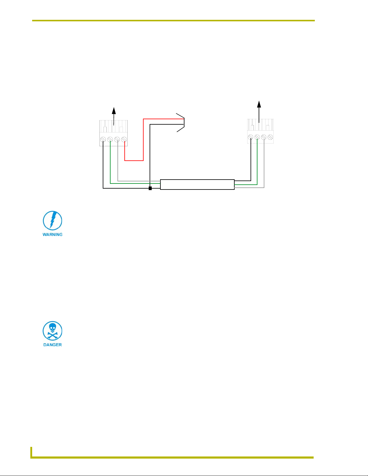
Using the 4-pin AXlink for data with external power supply
To use the AXlink 4-pin Phoenix connector for data communication (with the Central Controller)
and power transfer (from a power supply), the incoming PWR and GND cable from the power
supply must be connected to the AXlink cable connector going to the touch panel. FIG. 19 shows
the external power supply diagram.
To the Touch Panel’s
AXlink/PWR connector
PWR (+)
GND (-)
Top view
GND -
AXM/RX
AXP/TX
FIG. 19 AXlink connector wiring diagram (using external power source)
Local +12 VDC
power supply
(coming from
the power
supply)
To the external Controller device
Top view
GND -
AXP/TX
AXM/RX
When you connect an external power supply, do not connect the wire from the PWR
terminal (coming from the external device) to the PWR terminal on the Phoenix
connector attached to the Controller unit. Make sure to connect only the AXM, AXP,
and GND wires to the Controller’s Phoenix connector when using an external power
supply.
Make sure to connect only the GND wire on the AXlink/PWR connector when using a separate
12 VDC power supply. Do not connect the PWR wire to the AXlink connector’s PWR (+)
opening.
18
1. Unscrew the PWR and GND wires on the terminal end of the power supply’s 2-pin cable.
2. Pair the GND wires from the power supply and Central Controller AXlink connectors together;
insert them into the clamp position for GND on the touch panel AXlink connector.
3. Tighten the clamp and secure the two GND wires.
Never connect both power wires from the power supply and Central Controller to the
PWR terminal on the touch panel AXlink connector. Only the power supply PWR wire
should be connected to the touch panel AXlink connector. If both sources are used to
provide power to the touch panel, an electrical hazard is created and the threat of
both equipment damage and personal injury is likely.
4. Place the PWR wire from the power supply into the open clamp position for PWR on the touch
panel AXlink connector.
6" Color Video Touch Panels
Page 23

Installation
Using a BNC video cable to provide video input
Connect the control system’s video connector to the rear of the AXD-CV6 using a BNC cable to
provide a video feed, as seen in FIG. 20.
BNC (female) connector
GND (-)
Video wire
Rear panel
view AXD-CV6
FIG. 20 BNC cable connection from the AXD-CV6 to the video source
Some installations may require a 90° right-angle BNC adapter to accommodate a
sharp bend in the video cable. Be careful not to crimp the video cable and possibly
damage the BNC connector by bending the video cable too far.
BNC (male) connectors
Female video
source connector
Using the (DB-9) RS-232 connector for mouse control or data
The dual-function (DB-9) RS-232 connector supports most standard serial mouse control devices
and RS-232 communication protocols for PC data transmission. The following table lists the (DB-
9) RS-232 connector pinouts and FIG. 21 shows the (DB-9) RS-232 connector and power supply
wiring diagram.
(DB-9) RS-232 Connector Pinouts
Pin Signal Function
1 N/A Not used
2 RXD Receive data
3 TXD Transmit data
4 DTR Data terminal ready (not used)
5 GND Signal ground
6 DSR Data set ready (not used)
7 RTS Request to send (not used)
8 CTS Clear to send (not used)
9 N/A Not used
9
8
7
6
Female
5
4
3
2
1
Male
9
8
7
6
Use connector pins 2, 3, and 5 for data and ground. For some applications, you may need to strap
pins 7 (request to send) and 8 (clear to send) together, depending on the PC.
6" Color Video Touch Panels
19
Page 24

Installation
+ (PWR)
- (GND)
Power connector
12 VDC power supply
5 (GND)
3 (TXD)
2 (RXD)
Touch panel
DB-9 connector
FIG. 21 DB-9 RS-232 connector and power supply wiring diagram
Male
Female
Optional 7 to 8-pin
connector
5 (GND)
3 (TXD)
2 (RXD)
Mouse or PC, DB-9 connector
20
6" Color Video Touch Panels
Page 25

Designing Touch Panel Pages
There are two ways to approach creating touch panel pages:
TPDesign3 - Refer to the TPDesign3 Touch Panel Program (Version 3. 16) instruction
manual for more information.
On-board editor
This document describes basic use of the on-board editor to create pages and buttons. Refer to the
G3 Firmware Design and Reference instruction manual for more detailed firmware information.
Buttons
Standard button types include rectangles and other geometric shapes you can create with the touch
panel editor. Buttons are set with attributes, meaning there is a response from the Central Controller
when you touch the button.
General buttons are part of the default touch panel program and cannot be changed. General buttons
create or revise pages and specify panel communication parameters. Button examples include
selection buttons, information buttons, adjustment buttons, and operation bars. The general button
categories are described in the table below.
Designing Touch Panel Pages
General Button Categories
Selection buttons Selection buttons appear on touch panel pages and set communica-
Information buttons Information buttons contain serial numbers and firmware version
Adjustment buttons You can use the UP and DN buttons to set adjustment buttons. The
Keypad buttons The keypad button opens a keypad so you can enter a password or
Decision buttons Decision buttons appear when an operation has two options and
tion parameters.
information. The properties of these buttons cannot be changed.
These buttons have a dark fill and light text.
adjustment button example sets the baud rate for the connection
from the touch panel to the computer.
value assignment. All keypad buttons are interactive except for the
entry display.
requires verification before an action is performed.
6" Color Video Touch Panels
21
Page 26

Designing Touch Panel Pages
General Button Categories (Cont.)
Status buttons Status buttons always have a dark fill with light letters and have no
functionality except to display information.
Operation bars Operation bars appear in the place of the Editor bar, after selecting a
Touch to Continue buttons "Touch to Continue" buttons appear when an operation requires user
Joystick buttons Joysticks are vertical and horizontal direction controllers for use with
Bargraph buttons Bargraph buttons display a dynamic bargraph (vertical or horizontal).
button or page edit operation. The operation bar indicates which edit
function is currently active. When an edit operation is selected, it
remains active until you press EXIT.
acknowledgement.
pan and tilt camera controllers.
An example is the battery level indicator button.
Activating Edit Mode
Before designing touch panel pages and buttons, you must activate Edit mode. Once activated, use
EDIT button to enter Edit mode. This mode has options to add and configure touch panels and
the
buttons. When powering up the touch panel, the first page is the Main page (see FIG. 22). Note that
the Edit button is not available initially. If you have a pre-programmed panel, you may not see the
Main page.
22
FIG. 22 Main Page
To activate edit mode:
1. Press
2. Press
SETUP in the Main page to open the Setup page (FIG. 23).
PROTECTED SETUP to open the keypad.
3. Enter 1988 (default password) in the keypad and press
you press
ENTER after typing an incorrect password, you are immediately returned to the
previous page.
ENTER to open Protected Setup page. If
6" Color Video Touch Panels
Page 27

Designing Touch Panel Pages
FIG. 23 Setup page
4. Press EDITOR to enable Edit mode. The EDITOR button is highlighted in the Protected Setup
page when enabled, as shown in FIG. 24.
FIG. 24 Protected Setup page with the active EDITOR button
5. Press
6. Press
EXIT to close the Protected Setup page and return to the Setup page (now the Edit mode).
EXIT again to return to the Main page. The EDIT button appears at the top of the page
indicating Edit mode is active.
7. Press
EDIT to open the Edit bar. The BUTTON and PAG E options, in the Edit bar, (FIG. 25) are
used to design and modify button and page settings.
FIG. 25 Main page with Edit bar
Edit bar
6" Color Video Touch Panels
23
Page 28

Designing Touch Panel Pages
Setting the Device Base
Press the DEVICE BASE option, in the Protected Setup page (FIG. 24), to assign a base (starting)
device address to the touch panel.
1. Enter the base address for the touch panel. The base address range is from 1 - 255. Standard
device addresses begin at 128.
2. Press
ENTER to save.
Setting the Device Used
Use the DEVICE USED option in the Protected Setup page (FIG. 24) to assign a value for the
number of devices being controlled by the touch panel.
1. Press
DEVICE USED to open the keypad and enter the panel’s device number from 1 - 4. Each
device number supports up to 255 programmable channel codes. The multiple device settings
allow you to create up to four unique touch panel buttons and/or pages. This value is used to
determine the current device being used by the panel.
2. Enter the number of devices being used by the touch panel.
3. Press
ENTER to save the value.
Adding a Page
1. Press PAG E on the Edit bar to open the PAG E menu.
2. Press
3. Press
Setting the page color
ADD to open the keyboard and enter a name for the new page. Page names can be up to
20 characters.
EXIT CHANGE to save, close the keyboard, and go to the new page.
1. Press
2. Press
3. Press
EDIT to open the Edit bar on the newly created page.
PAG E on the Edit bar to open the PAG E menu.
PAG E C OL O R to open the color palette.
4. Select a color from the palette; the page automatically changes to the new color.
Adding a Button
To add a button to the current page:
1. Press
2. Press
Resizing a button
1. Press
2. Press
BUTTON on the Edit bar to open the BUTTON menu.
ADD to open the ADD BUTTON operation bar. On the LCD screen, touch and drag to
create a button. The first touch point is the upper-left corner of the button.
BUTTON on the Edit bar to open the BUTTON menu.
RESIZE. Then, touch any edge of the button and drag. Removing your finger from the
panel saves the button dimensions.
24
6" Color Video Touch Panels
Page 29

Designing Touch Panel Pages
Defining On-Screen and External Button Properties
External pushbuttons are configured with features similar to on-screen buttons. Their functionality
can be set just as any other button on the touch panel.
Use the
PROPERTIES option of the BUTTON menu in the Edit bar to set button borders, page flips,
button colors for channel on/off conditions, channel/variable text codes, and string/macro
assignments.
External button properties include only the button type, page flips, channel codes, and string/macro
assignments. Although the Border and Color sections of this page appear, they are of no use to
external pushbuttons since they do not appear on-screen.
To set button properties:
1. Press
2. Press
BUTTON on the Edit bar to open the BUTTON menu options.
PROPERTIES to open the PROPERTIES operation bar.
3. Press the new button to open the Button Properties page. This page lists the properties for the
active button.
4. Press
BUTTON TYPE; this opens the BUTTON TYPE menu.
5. Choose a button type for the selected button to open the associated Button Properties page.
Each button type has its own Button Properties page with settings specific to the button.
6. Press
7. Select a border to set for the button and return to the Button Properties page. The
BORDER to open the BUTTON BORDER pages.
BORDER
button changes to show the selected border type.
Setting the channel code
The channel button sets the device and button channel codes. Channel codes and variable text codes
work the same for all button types, including joysticks and bargraphs.
1. In the Button Properties page, press
DEV to open the keypad and set the touch panel’s device
number.
2. Enter 1, 2, 3, or 4 in the keypad. The programming software uses device codes 1 - 4 to identify
the touch panel. Refer to the G3 Firmware Design and Reference instruction manual for more
information.
If DEVICE USED is set to 4 and Base Device Number is 128, the Controller recognizes
bus devices 128 - 131.
The panel will not allow you to enter a device number greater than the DEVICE USED
without first displaying a decision box asking if you accept the new selection or not.
3. Press
ENTER to save the device number, close the keypad, and return to the Button Properties
page.
4. Press
CHAN to open the keypad and enter a channel value of 1 - 255. The source code uses the
channel code number to identify the button and its programmed operations. The channel code
for non-active buttons is 0.
5. Press
ENTER to save the channel number, close the keypad, and return to the Button Properties
page.
6" Color Video Touch Panels
25
Page 30

Designing Touch Panel Pages
Setting the variable text code
The variable text buttons set the device and button channel codes for the buttons.
1. Press
DEV to open the keypad and set the device number.
2. Enter 1, 2, 3, or 4 in the keypad. The source code uses device codes 1 - 4 to identify the touch
panel.
3. Press
4. Press
ENTER to save, close the keypad, and return to the Button Properties page.
CHAN to open a keypad and set the channel number.
5. Enter a channel value of 1 - 255 in the keypad. The source code uses the channel code number
to identify the button and its operations.
6. Press
ENTER to save the channel number, close the keypad, and return to the Button Properties
page.
Setting the page flip
1. Press the
TYPE menu.
Page FLIP type
button
FIG. 26 Page FLIP Type button
PAG E FL I P TYPE button (FIG. 26) in the Button Properties page to open the PAGE FLIP
Flip to Page button
2. Select a Page Flip type. If you select
P
AGE button appears.
3. Press the
FLIP TO PAGE button (FIG. 26) to open a list of all the saved touch panel pages. If the
FLIP STANDARD in the PAGE FLIP TYPE menu, the FLIP TO
desired page is not present in the menu, check to verify the page has been saved.
4. Select the target page for the page flip.
Setting the button colors for channel-off conditions
1. Press any button to open the Button Properties page.
2. Press
BORDER under CHANNEL OFF in the Button Properties page. The color palette appears.
Select a color to set as the border.
3. Press the
FILL button in the Button Properties page to open the palette. Select a color to set as
the fill.
4. Press the
5. Press
TEXT button to open the palette. Select a color to use for the text.
EXIT SAVE CHANGE in the Button Properties page to save the new button properties and
return to the current page.
Adding text, icons, and bitmaps to a button
1. Press
2. Press
BUTTON on the Edit bar to open the BUTTON menu.
TEXT/IMAGE to add text to the button. The TEXT/IMAGE operation bar appears.
26
3. Press any button to open the Text/Image page.
6" Color Video Touch Panels
Page 31

Designing Touch Panel Pages
4. Go through each option and set as desired:
TEXT OFF and TEXT ON sets the text for the button's Off and On state.
ICON OFF and ICON ON sets the icon for the button's Off and On state.
BITMAP OFF and BITMAP ON sets the bitmap for the button's Off and On state.
MAKE ON SAME AS OFF sets the On and Off properties the same.
You cannot create or edit buttons with Unicode fonts on the panel. Any use of the
TEXT/IMAGE button to alter or create Unicode font supported buttons must be done
in the TPDesign3 Touch Panel Design Program.
5. Press
EXIT SAVE CHANGE to close the Text/Image page and return to the Main page.
Using TPDesign3 to Download Bitmaps, Icons, and Fonts
TPDesign3 allows you to download bitmaps, icons, and fonts into your touch panel from an
existing touch panel program. Refer to the TPDesign3 Touch Panel Program instruction manual for
more information. Use the Download to Panel button to download a project file.
To download bitmaps, icons and/or fonts from an existing TPDesign3 project file:
1. Launch the TPDesign3 software program and open a project file that contains the desired
bitmaps, icons, and fonts.
2. Select File from the menu bar to open the File menu.
3. In the File menu, click on Download to Panel, this opens the Download to Panel dialog box.
4. Click on the Comm Settings tab to set the communications port, baud rate, and other settings.
5. Then, click the Actions tab to set the communication mode and select which elements of the
project file you want to download to the touch panel.
6. In the What To Send area, select one or more of the available options (All Bitmaps, All Icons,
All Fonts).
7. Select the mode of communication with the touch panel (RS-232 and AXlink). Confirm that
the correct panel is selected by verifying the ID values with the Base Address assigned to the
touch panel in the Protected Setup page.
8. After clicking Connect, the Available Panels list appears in the Available Panels field. Click
Begin to start downloading the project file into the panel.
9. After completing the download, the bitmaps, icons and fonts that were downloaded are now
accessible via the BITMAPS, ICONS and FONTS menus.
Creating a Bargraph and Joystick
Bargraphs are level monitors and adjustable level controls. These levels can be configured to
monitor and adjust audio outputs and lighting levels.
Joysticks are vertical and horizontal direction controllers you can use for camera for pan and tilt
control. Before starting, make sure to connect the touch panel to your Controller; otherwise, the
joystick will not work properly.
6" Color Video Touch Panels
27
Page 32

Designing Touch Panel Pages
Adding a bargraph or joystick button\
Create a new button using the Add operation bar in the
1. Press
2. Press
BUTTON in the Edit bar to open the BUTTON menu.
PROPERTIES in the BUTTON menu to open the PROPERTIES operation bar.
BUTTON menu.
3. Press any button to open the Button Properties page.
4. Press
BUTTON TYPE to open the BUTTON TYPE menus. Choose a button type to open its
Button Properties page.
Setting Bargraph and Joystick Properties
Use the Button Properties page to set channel, level, and button colors. Refer to the Setting the
variable text code section on page 26 and the Setting the channel code section on page 25 for
further information. Refer to the Setting the button colors for channel-off conditions section on
page 26 for more information on colors for channel-off conditions.
Setting the level code
Level buttons set the device and number codes for the touch panel.
Joysticks use two level numbers. The first is for the X-axis and the second for the Yaxis. You only need to specify the first level.
1. Press
DEV to open a keypad and set the device number.
2. Enter 1, 2, 3, or 4 in the keypad. The programming software uses device codes
1 - 4 to identify the touch panel.
3. Press
ENTER to save the level device number, close the keypad, and return to the Button
Properties page.
4. Press
NUM to open a keypad and set the level number assigned to the device.
5. Enter a number 1 – 8. Each device can have from 1 – 8 levels except joysticks, where the range
is 1 – 7.
6. Press
ENTER to save, close the keypad, and return to the Button Properties page.
28
6" Color Video Touch Panels
Page 33

Programming
You can program the touch panel, using the commands in this section, to perform a wide variety of
operations using Axcess Send_Commands and variable text commands. Use the commands
described in this section to program the touch panel.
Serial Commands
Serial Commands are used in the AxcessX Terminal Emulator mode. These commands are case
insensitive.
Serial Commands
?PAR
Returns panel
parameters to the
PC terminal.
$SC
Sends a serial
port
send_command
within a panel, as
if sent from
Axcess.
CALIBRATE
Starts touch panel
calibration.
CHECK CAL
Enters the calibration test mode.
Programming
Panel parameters include: firmware version, device number, mouse type, output resolution, number of devices, cursor enable, brightness (always=0), and contrast (always=0).
Syntax:
"?PAR"
Example:
?PAR
Requests the information.
Syntax:
"$SC <device offset>,"’<send_command>,<variable
text #>,<data>’""
Var iables :
device offset = Device number
variable text # = The variable text number value on the touch panel.
Example:
$SC 1,"’@TXT’,2,’TEXT’"
The string is sends the command to put text on a button with a variable text value of 2. It is
crucial that all the correct ’ and " be used with no spaces after the commas.
Example:
$SC 1,"’SLEEP’"
Sets a touch panel to sleep.
Syntax:
"CALIBRATE"
Example:
CALIBRATE
Starts the calibration sequence mode on the touch panel.
Syntax:
"CHECK CAL"
Example:
CHECK CAL
Begins the calibration check mode on the touch panel.
6" Color Video Touch Panels
29
Page 34

Programming
Serial Commands (Cont.)
ECHO ON
Turns On character echo.
ECHO OFF
Turns Off character echo.
GET CAL
Gets the calibration variables.
HELLO
Verifies that serial
communication is
working properly.
MOUSE
Turns on serial
mouse or other
touch devices.
RESET
Cycles power on
the touch panel.
SET CAL
Sets the calibration variables.
Syntax:
"ECHO ON"
Example:
ECHO ON
The character echo is sent back to the computer.
Syntax:
"ECHO OFF"
Example:
ECHO OFF
The character echo is not sent back to the computer.
Syntax:
"GET CAL"
Example:
GET CAL
Gets the calibration variables on the touch panel.
Syntax:
"HELLO"
Example:
HELLO
If the communication is active and working, the response is "How are you doing?".
Syntax:
MOUSE <mouse type>
Var iables :
mouse type =
00: Mouse cursor Off
01: Microsoft
Example:
MOUSE 01
Turns on Microsoft® compatible serial mouse. Refer to the @MOU section on page 42 for
the chart describing the BIT information and definitions.
Syntax:
"RESET"
Example:
RESET
Cycles the power on the touch panel. Once the firmware is downloaded, send this command to recycle power to the panel. This command prevents the user from having to physically re-cycling power on the unit.
Syntax:
“SET CAL <X Multiplier> <X Offset> <Y Multiplier> <Y
Offset>"
Example:
SET CAL 2F 3A 2B 62
Sets the calibration values on the touch panel.
®
serial mouse/cursor On
30
6" Color Video Touch Panels
Page 35

Serial Commands (Cont.)
SETUP
Puts the touch
panel on the
Setup Page.
VER
Restores the current version.
WORKING?
Verifies the communication
between the touch
panel and the Terminal Emulator.
ZAP!
Clears all memory.
Syntax:
"SETUP"
Example:
SETUP
Flips the touch panel to the Setup page.
Syntax:
"VER"
Example:
VER
Returns the current version of the main firmware.
Syntax:
"WORKING?"
Example:
WORKING?
Response:
$SC 1,"’CPAGE72-Main Page’"
Responding touch panel turns its Main page the color white. This command verifies serial
communication. The CV6 panel must have a page named Main Page for this command to
work properly.
Syntax:
"ZAP!"
Example:
ZAP!
Clears all memory and erases all buttons, pages, drawings, and symbols.
Programming
Only use the ZAP! command to erase the saved data in the touch panel; data cannot be
recovered after it is erased.
System Send_Commands
System Send_Commands are stored in the Controller and direct the touch panel to perform various
operations.
System Send_Commands
$SP
Sends data out
the serial port with
trailing CR and LF.
ABEEP
Outputs one panel
beep even if the
beep value is set
to 0 in the Setup
page.
Translates the ¦ and translates it as a carriage return to the next line.
Syntax:
"’$SP "<data>"’"
Example:
SEND_COMMAND TP,"’$SP "CALIBRATE"’"
Sends the Calibrate command to another panel through the Serial Port. It is crucial that all
the correct ’ and " be used with no spaces after the commas.
Syntax:
"’ABEEP’"
Example:
SEND_COMMAND TP,"’ABEEP’"
Beeps the panel.
6" Color Video Touch Panels
31
Page 36

Programming
System Send_Commands (Cont.)
ADBEEP
Outputs a double
beep even if the
double beep value
is set to 0 in the
Setup page.
AKEYB
Opens the touch
panel keyboard
and initializes the
text string entry.
AKEYP
Opens the touch
panel keypad and
initializes the
number string
entry.
AKEYR
Closes/opens the
touch panel keyboard/pad.
BAUD
Sets the program
port baud rate.
BEEP
Gives an output of
one beep.
Syntax:
"’ADBEEP’"
Example:
SEND_COMMAND TP,"’ADBEEP’"
Double beeps the panel.
The keyboard string is set to null during power-up and stored until power-down.
Syntax:
"’AKEYB-<text string>’"
Var iable:
text string = 0 - 59 characters
Example:
SEND_COMMAND TP,"’AKEYB-TOUCH HERE’"
Opens the touch panel keyboard with TOUCH HERE in the display.
The keyboard string is set to null during power-up and stored until power-down.
Syntax:
"’AKEYP-<number string>’"
Var iable:
number string = 0 - 9999
Example:
SEND_COMMAND TP,"’AKEYP-1988’"
Opens the touch panel keypad with 1988 in the display.
Syntax:
"’AKEYR’"
Example:
SEND_COMMAND TP,"’AKEYR’"
Closes the keyboard/keypad opened using the ’AKEYB’, ’AKEYP’, or ’PKEYP’
commands.
The baud rate can also be set in the Protected Setup page’s BAUD level indicator.
Syntax:
"’BAUD <baud rate>’"
Var iable:
baud rate = 38400, 19200, 9600, 4800, 2400, 1200, 600, and 300
Example:
SEND_COMMAND TP,"’BAUD 38400’"
Sets the Baud rate to 38400.
This beep command sounds one tone for a time length of 50 milliseconds.
Syntax:
"’BEEP’"
Example:
SEND_COMMAND TP,"’BEEP’"
Activates one beep tone. Beeps the panel if the Beep button is not set to 0.
The BEEP command will disable the beep after a QBEEP command.
32
6" Color Video Touch Panels
Page 37

System Send_Commands (Cont.)
BRIT
Adjusts brightness
of display.
CALIBRATE
Starts the touch
panel calibration
sequence.
CLOCK
Sets the time and
date.
CURSOR
Turns the cursor
display On or Off if
the touch device
has a cursor.
DBEEP
Gives a double
beep output.
ILEV
Inverts the joystick
axis.
Syntax:
"’BRIT-<level>’"
Var iable:
level = 1 - 8 (1 = minimum; 8 = maximum)
Example:
SEND_COMMAND TP,"’BRIT-8’"
Sets to highest brightness level.
Syntax:
"’CALIBRATE’"
Example:
SEND_COMMAND TP,"’CALIBRATE’"
Starts the calibration operation on the touch panel.
Syntax:
"’CLOCK <mm-dd-yy> <hh:mm:ss>’"
Var iables :
mm = 01 - 12, dd = 01 - 31, yy = 00 - 99
hh = 00 - 23, mm = 00 - 59, ss = 00 - 59
Example:
SEND_COMMAND TP,"’CLOCK 02-08-98 19:16:00’"
Sets the touch panel’s date to February 8, 1998, and time to 7:16 p.m.
Syntax:
"’CURSOR <OFF/ON>’"
Var iables :
Off = 0 and On = 1
Example:
SEND_COMMAND TP,"’CURSOR 0’"
Turns the cursor display Off.
This command only works if the Double Beep value in the Protected Setup page is set to
On.
Syntax:
"’DBEEP’"
Example:
SEND_COMMAND TP,"’DBEEP’"
Double beeps the panel.
Syntax:
"’ILEV <joystick axis to invert>’"
Var iables :
joystick axis to invert =
0 : Normal G3 joystick (origin: top left)
1 : Invert horizontal axis (origin: top right)
2 : Invert vertical axis (origin: bottom left)
3 : Invert both axes (origin: bottom right)
Example:
SEND_COMMAND TP,"’ILEV 3’"
Inverts the joystick axis to move the origin to another corner.
Programming
6" Color Video Touch Panels
33
Page 38

Programming
System Send_Commands (Cont.)
MOUSE
Turns on serial
mouse or other
touch devices.
PAG E
Flips to a page
with a specified
page name.
PKEYP
Displays asterisks (*) for keypad
entries.
PPOF
Closes a specific
popup page.
PPON
Opens a specific
popup page.
QBEEP
Stops all beeps.
Syntax:
"’MOUSE <mouse condition>’"
Var iables :
mouse condition =
00: Mouse cursor Off
01: Microsoft
Example:
®
serial mouse/cursor On
SEND_COMMAND TP,"’MOUSE 01’"
Turns on Microsoft® compatible serial mouse. Refer to the @MOU section on page 42 for
the chart describing the BIT information and definitions.
Syntax:
"’PAGE-<page name>’"
Var iable:
page name = 1 - 50 ASCII characters
Example:
SEND_COMMAND TP,"’PAGE-MAIN PAGE’"
Flips the touch panel to the page named MAIN PAGE.
Syntax:
"’PKEYP-<number string>’"
Var iable:
number string = 0 - 9999
Example:
SEND_COMMAND TP,"’PKEYP-1988’"
Displays the touch panel keypad with **** instead of 1988.
Syntax:
"’PPOF-<page name>’"
Var iable:
page name = 1 - 50 ASCII characters
Example:
SEND_COMMAND TP,"’PPOF-Popup Page 1’"
Closes Popup Page 1.
Syntax:
"’PPON-<page name>’"
Var iable:
page name = 1 - 50 ASCII characters
Example:
SEND_COMMAND TP,"’PPON-Popup Page 1’"
Opens Popup Page 1.
Syntax:
"’QBEEP’"
Example:
SEND_COMMAND TP,"’QBEEP’"
Stops all beeps, including "’ABEEP’", "’ADBEEP’", and AXlink beeps.
34
6" Color Video Touch Panels
Page 39

System Send_Commands (Cont.)
RESET
Cycles power on
the touch panel.
SETUP
Goes to the Setup
page.
SLEEP
Forces the touch
panel to screen
saver mode.
TPAGEOFF
Deactivates page
tracking.
TPAGEON
Activates page
tracking.
WAKE
Deactivates
screen-saver
mode and resets
the sleep timer.
XMRT
Sets the new network communication retry value for
the panel and
SoftROM.
XMTO
Sets the new network communication delay for the
panel and SoftROM.
Syntax:
"RESET"
Example:
RESET
Cycles the power on the touch panel. Once the firmware is downloaded, send this command to recycle power to the panel. This command prevents the user from having to physically re-cycling power on the unit.
Syntax:
"’SETUP’"
Example:
SEND_COMMAND TP,"’SETUP’"
Flips the touch panel to the Setup page.
Syntax:
"’SLEEP’"
Example:
SEND_COMMAND TP,"’SLEEP’"
Activates the screen saver mode.
Syntax:
"’TPAGEOFF’"
Example:
SEND_COMMAND TP,"’TPAGEOFF’"
Deactivates the page tracking option.
See page 36 for a more detailed explanation.
Syntax:
"’WAKE’"
Example:
SEND_COMMAND TP,"’WAKE’"
Deactivates the touch panel screen-saver mode and resets the sleep timer.
Syntax:
"’XMRT <number>’"
Var iable:
number = 1 - 15 ASCII characters
Example:
SEND_COMMAND TP,"’XMRT 9’"
Sets the XMODEM wait for character retries to 9.
Syntax:
"’XMTO <number>’"
Var iable:
number = 4 - 30 ASCII characters
Example:
SEND_COMMAND TP,"’XMTO 5’"
Sets the new XMODEM character delay time to 5 seconds.
Programming
6" Color Video Touch Panels
35
Page 40

Programming
System Send_Commands (Cont.)
TPAGEON
Activates page
tracking.
Syntax:
"’TPAGEON’"
Example:
SEND_COMMAND TP,’TPAGEON’
DEFINE_DEVICE
TP1 = 128 (*AMX Touch Panel*)
TP2 = 129 (*AMX Touch Panel*)
DEFINE_VARIABLE
TP1_BUFFER[100] (*Buffer for TP1*)
TP2_BUFFER[100] (*Buffer for TP2*)
TRASH[50] (*For Parsing Above*)
DEFINE_START
CREATE_BUFFER TP1,TP1_BUFFER
CREATE_BUFFER TP2,TP2_BUFFER
SEND_COMMAND TP1,'TPAGEON'
SEND_COMMAND TP2,'TPAGEON'
DEFINE_PROGRAM
(* PAGE TRACKING ROUTINE *)
IF(LENGTH_STRING(TP1_BUFFER))
{
IF(FIND_STRING(TP1_BUFFER,'PAGE-',1))
{
TRASH=REMOVE_STRING(TP1_BUFFER,'PAGE-',1)
SEND_COMMAND TP2,"'PAGE-',TP1_BUFFER"
CLEAR_BUFFER TP1_BUFFER
}
IF((FIND_STRING(TP1_BUFFER,'PPON-',1))
OR(FIND_STRING(TP1_BUFFER, 'PPOF-',1)))
{
SEND_COMMAND TP2,TP1_BUFFER
CLEAR_BUFFER TP1_BUFFER
}
}
36
IF(LENGTH_STRING(TP2_BUFFER))
{
IF(FIND_STRING(TP2_BUFFER,'PAGE-',1))
{
TRASH=REMOVE_STRING(TP2_BUFFER,'PAGE-',1)
SEND_COMMAND TP1,"'PAGE-',TP2_BUFFER"
CLEAR_BUFFER TP2_BUFFER
}
IF((FIND_STRING(TP1_BUFFER,'PPON-',1)) OR
(FIND_STRING(TP1_BUFFER,'PPOF-',1)))
{
SEND_COMMAND TP1,TP2_BUFFER
CLEAR_BUFFER TP2_BUFFER
}
}
(* The command string is sent to the Controller in the ’PAGE-(page name)’ or ’PPON/
PPOF-(page name)’ format. The string is captured in the buffer for one panel and sent to
the other panel. If panels are combined using the DEFINE_COMBINE statement, the routine needs to be written only once, and the command is sent back to the same panel. *)
(* END OF PAGE TRACKING ROUTINE *)
6" Color Video Touch Panels
Page 41

Programming
System Send_Commands (Cont.)
ZAP!
Clears all memory; erases buttons, pages,
drawings, and
symbols.
Only use the ZAP! command to erase the saved data in the touch panel; data cannot be
recovered after it is erased.
Syntax:
"’ZAP!’"
Example:
SEND_COMMAND TP,"’ZAP!’"
Clears all memory and erases all buttons, pages, drawings, and symbols.
Video Send_Commands
Video Send_Commands direct the touch panel to perform various video specific operations.
Video Send_Commands
@VBR
Sets the video signal brightness.
@VBW
Sets the video to
black/white or
color.
@VCT
Sets the video
contrast.
Syntax:
"’@VBR <ASCII setting for Brightness>’"
Var iables :
ASCII brightness setting = 0 (min) - 255 (max)
Example:
SEND_COMMAND TP,"’@VBR 128’"
Sets the video brightness to 128.
Syntax:
"’@VBW <ASCII setting for Black/White input>’"
Var iables :
Black/White input setting = 0: Color
1: Black and White
Example:
SEND_COMMAND TP,"’@VBW 1’"
Sets the video output to black and white.
Syntax:
"’@VCT <ASCII setting for Contrast>’"
Var iables :
ASCII contrast setting = 0 (min) - 255 (max)
Example:
SEND_COMMAND TP,"’@VCT 128’"
Sets the video contrast to 128.
6" Color Video Touch Panels
37
Page 42

Programming
Video Send_Commands (Cont.)
@VDD
Sets the video
setting for autodetection or manual detection of
the video standard.
@VFF
Video Fast Forward Mode Alogrithm.
@VHU
Sets video hue.
@VSD
Resets video
default settings.
@VST
Sets the video
saturation.
Syntax:
"’@VDD <ASCII settings for video detection>’"
Var iables :
ASCII detection settings = 1: Auto-detect video input
2: Manual set NTSC
3: Manual set PAL
4: Manual set SECAM
Example:
SEND_COMMAND TP,"’@VDD 3’"
Detects only PAL.
The algorithm creates independent vertical sync 60 Hz/50 Hz (NTSC/PAL or SECAM) timing, ignoring the sync from the VCR. During fast forward on many VCRs, the vertical sync
timing increases by 8 Hz, thus, causing the video pictures to freeze on our digital hardware.
Syntax:
"’@VFF <ASCII video fast forward settings>’"
Var iables :
ASCII video settings = 0: Normal
1: On
2: Off (required for Tanberg’s non-interlacing equipment)
Example:
SEND_COMMAND TP,"’@VFF 2"
Turns the algorithm Off.
Syntax:
"’@VHU <ASCII setting for Hue>’"
Var iables :
ASCII hue setting = 0 (min) - 255 (max)
Example:
SEND_COMMAND TP,"’@VHU 128’"
Sets video hue to 128.
Resets the following video attributes to their default settings:
Brightness, Contrast, Saturation, Hue, Interlace
Syntax:
"’@VSD’"
Example:
SEND_COMMAND TP,"’@VSD’"
Resets the video defaults.
Syntax:
"’@VST <ASCII setting for Saturation>’"
Var iables :
ASCII saturation setting = 0 (min) - 255 (max)
Example:
SEND_COMMAND TP,"’@VST 128’"
Sets video saturation to 128.
38
6" Color Video Touch Panels
Page 43

Programming
Programming Numbers
The following information provides the programming numbers for colors, fonts, and borders.
Colors can be used to set the colors on buttons, sliders, gauges, and pages. The lowest color number
represents the lightest color-specific display; the highest number represents the darkest display. For
example, 0 represents light red, and 5 is dark red.
Colors and Programming Numbers
Color No. Color No.
Red 0 - 5 Purple 54 - 59
Orange 6 - 11 Magenta 60 - 65
Yellow 12 - 17 Pink 66 - 71
Lime 18 - 23 White 72 - 77
Green 24 - 29 Light Gray 78 - 83
Aqua 30 - 35 Dark Gray 84 - 86
Cyan 36 - 41 Black 87
Royal 42 - 47 Transparent 255
Blue 48 - 53
Font styles are used to program the text fonts on buttons, sliders, gauges, and pages. Programming
numbers are assigned consecutively when downloaded to the touch panel.
Font Styles and Programming Numbers
No. Font styles No. Font styles
1 Extra small 5 Extra large
2 Small 6 Hollow medium
3 Medium 8 Hollow extra large
4 Large 32 - 255 Variable fonts
You must import variable text fonts into a TPDesign3 project file, and download the
project file containing the fonts to the touch panel. The variable fonts are
programming numbers assigned by the touch panel during the download process.
Border styles can be used to program borders on buttons, sliders, and gauges.
Border Styles and Programming Numbers
No. Border styles No. Border styles
0 No border 11 Double shadow
1 No border special 20 3-dimensional rectangle 1
2 Single line 21 3-dimensional rectangle 2
3 Double line 22 3-dimensional round 1
4 Triple line 23 3-dimensional round 2
5 Single rounded 24 3-dimensional neon 1
6 Double rounded 25 3-dimensional neon 2
7 Single raised 26 3-dimensional neon blue
8 Double raised 27 3-dimensional neon green
9 Triple raised 40 Single diamond
10 Double-line two single 41 Double diamond
6" Color Video Touch Panels
39
Page 44

Programming
Shorthand Send_Commands
The shorthand commands operate control equipment just like standard Send_Commands still used
in a wide variety of AMX products. However, shorthand commands are smaller byte-for-byte, and
are processed more efficiently.
The table below lists the shorthand Send_Commands you can use with the AXD-CV6 touch panel.
The shorthand command data is 1-byte, non-ASCII format except for pages, passwords, text, and
bitmap names.
Shorthand Send_Commands
@CBF
Sets the OFF
feedback border
color to the specified color.
@CBN
Sets the ON feedback border color
to the specified
color.
@CFF
Sets the OFF
feedback fill color
to the specified
color.
@CFN
Sets the ON feedback fill color to
the specified
color.
This works only if the specified background color is not the same as the current color.
Syntax:
"’@CBF’,<variable text address>,<color_number>"
Var iables :
variable text address = 1 - 255
color number = See the Colors and Programming Numbers table on page 39.
Example:
SEND_COMMAND TP,"’@CBF’,1,0"
Sets the OFF feedback border color to Red for the variable text button 1.
This works only if the specified background color is not the same as the current color.
Syntax:
"’@CBN’,<variable text address>,<color_number>"
Var iables :
variable text address = 1 - 255
color number = See the Colors and Programming Numbers table on page 39.
Example:
SEND_COMMAND TP,"’@CBN’,2,78"
Sets the ON feedback border color to Gray for variable text button 2.
This only works if the specified background color is not the same as the current color.
Syntax:
"’@CFF’,<variable text address>,<color_number>"
Var iables :
variable text address = 1 - 255
color number = See the Colors and Programming Numbers table on page 39.
Example:
SEND_COMMAND TP,"’@CFF’,1,72"
Sets the OFF feedback fill color to White for variable text button 1.
This only works if the specified background color is not the same as the current color.
Syntax:
"’@CFN’,<variable text address>,<color_number>"
Var iables :
variable text address = 1 - 255
color number = See the Colors and Programming Numbers table on page 39.
Example:
SEND_COMMAND TP,"’@CFN’,1,30"
Sets the ON feedback fill color to Aqua for variable text button 1.
40
6" Color Video Touch Panels
Page 45

Shorthand Send_Commands (Cont.)
@CPG
Sets the specified
page’s background color to
the specified
color.
@CPP
Sets the specified
page’s background color to
the specified
color.
@CTF
Sets the OFF
feedback text
color to the specified color.
@CTN
Sets the ON feedback text color to
the specified
color.
@IDF
The touch panel
returns its
MS-DOS file
name in a string.
This only works if the new background color is not the same as the current color.
Syntax:
"’@CPG’,<color_number>,’<page name>’"
Var iables :
color number = See the Colors and Programming Numbers table on page 39.
page name = 1 – 50 ASCII characters
Example:
SEND_COMMAND TP,"’@CPG’,87,’Main Page’"
Sets the page title to Main Page, and the color to Black.
This only works if the specified background color is not the same as the current color.
Syntax:
"’@CPP’,<color_number>,’<pop-up page name>’"
Var iables :
color number = See the Colors and Programming Numbers table on page 39.
pop-up page name = 1 – 50 ASCII characters
Example:
SEND_COMMAND TP,"’@CPP’,54,’Audio Page’"
Sets the popup page title to Audio Page, and the color to Purple.
This only works if the specified background color is not the same as the current color.
Syntax:
"’@CTF’,<variable text address>,<color_number>"
Var iables :
variable text address = 1 – 255
color number = See the Colors and Programming Numbers table on page 39.
Example:
SEND_COMMAND TP,"’@CTF’,1,48"
Sets the OFF feedback text color to Blue for variable text button 1.
This only works if the specified background color is not the same as the current color.
Syntax:
"’@CTN’,<variable text address>,<color_number>"
Var iables :
variable text address = 1 – 255
color number = See the Colors and Programming Numbers table on page 39.
Example:
SEND_COMMAND TP,"’@CTN’,1,72"
Sets the ON feedback text color to White for variable text button 1.
Syntax:
"’@IDF’"
Example:
SEND_COMMAND TP,"’@IDF’"
The touch panel returns its MS-DOS file name in a string.
Programming
6" Color Video Touch Panels
41
Page 46

Programming
Shorthand Send_Commands (Cont.)
@IDP
Queries the touch
panel to return a
string with the
TPDesign3
project name.
@MOU
Sets the serial
touch interface
type.
@PPA
Removes all
popup pages from
a specified page.
@PPF
Deactivates a
popup page on a
touch panel page.
@PPK
Deactivates a
popup page on all
touch panel
pages.
Syntax:
"’@IDP’"
Example:
SEND_COMMAND TP,"’@IDP’"
The touch panel returns a string containing the TPDesign3 project name.
When changing the serial touch device, you must connect the hardware before setting the
device type.
Syntax:
"’@MOU <touch_type>’"
Var iables :
touch type =
00: Mouse cursor Off
01: Microsoft
8000: Touch Output to Serial Port (Elo IntelliTouch)
Example:
®
serial mouse/cursor On
SEND_COMMAND TP,"’@MOU 01’"
Sets the touch interface to Microsoft serial mouse.
If no page is specified, the active page is used.
Syntax:
"’@PPA-<page name>’"
Var iable:
page name = target touch panel page name
Example:
SEND_COMMAND TP,"’@PPA-Main Page’"
If there were several popup pages on ’Main Page’ that are active, sending the previous
command would remove them all from that page.
If a page name is empty, the current page is used. If a pop-up page is part of a group, the
whole group is deactivated.
Syntax:
"’@PPF-<popup page name>;<page name>’"
Var iables :
popup page name = target popup page name
page name = target touch panel page name
Example:
SEND_COMMAND TP,"’PPF-Laser Disc 2 Transport Control;
Laser Disc Control Page’"
Deactivates the Laser Disc 2 Transport Control popup page on the Laser Disc Control
Page. If a page name is empty, the current page is used. If the popup page is part of a
group, the whole group is deactivated.
If a pop-up page is part of a group, the whole group is deactivated.
Syntax:
"’@PPK-<popup page name>’"
Var iable:
popup page name = target popup page name
Example:
SEND_COMMAND TP,"’@PPK-Laser Disc 2 Transport Control’"
Deactivates the Laser Disc 2 Transport Control popup page on all touch panel pages.
42
6" Color Video Touch Panels
Page 47

Shorthand Send_Commands (Cont.)
@PPN
Activates a popup
page on a touch
panel page.
@PPX
Removes all panel
popup pages.
@PWD
Sets the password
for the Page Flip
on the touch
panel.
@RDW
Redraws the current screen.
@SSL
Changes the
Sleep string sent
to the Controller
when the touch
panel activates
sleep mode.
@SST
Changes the Startup string sent to
the Central Controller when the
touch panel powers up.
If a page name is empty the current page is used.
Syntax:
"’@PPN-<popup page name>;<page name>’"
Var iables :
popup page name = popup page name
page name = page name
Example:
SEND_COMMAND TP,"’@PPN-Laser Disc 2 Transport Control;
Laser Disc Control Page’"
Activates the Laser Disc 2 Transport Control popup page on the Laser Disc Control Page.
The group that needs to be turned Off must contain the given popup page.
Syntax:
"’@PPX-<popup page>’"
Var iable:
popup page = popup page name
Example:
SEND_COMMAND TP,"’@PPX’"
Closes all popup pages from all of the pages in the panel.
Syntax:
"’@PWD-<page flip password>’"
Var iable:
page flip password = 0 - 9999
Example:
SEND_COMMAND TP,"’@PWD-1988’"
Sets the page flip password to 1988.
Syntax:
"’@RDW’"
Example:
SEND_COMMAND TP,"’@RDW’"
Sends a message to the touch panel to redraw the screen.
Syntax:
"’@SSL-<string>’"
Var iable:
string = alphanumeric characters
Example:
SEND_COMMAND TP,"’@SSL-Touch Panel Deactivated’"
Sends Touch Panel Deactivated to the Controller.
Syntax:
"’@SST-<string>’"
Var iable:
string = alphanumeric characters
Example:
SEND_COMMAND TP,"’@SST-Touch Panel Power On’"
Sends touch panel Power On to the Central Controller when the touch panel powers up.
Programming
6" Color Video Touch Panels
43
Page 48

Programming
Shorthand Send_Commands (Cont.)
@SWK
Changes the
Wakeup string
sent to the Controller when the
touch panel is
activated.
Syntax:
"’@SWK-<string>’"
Var iable:
string = alphanumeric characters
Example:
SEND_COMMAND TP,"’@SWK-Touch Panel Activated’"
Sends Touch Panel Activated to the Central Controller.
Color Send_Commands
Use the color Send_Commands to set the colors for text, buttons, and pages. Use the same
command for setting gray scale values only change the color number value to reflect the gray scale
(72-86) value.
Color Send_Commands
CALL
Sets the colors for
a variable text button.
You must use the variable text assignments to change button colors (see the Colors and
Programming Numbers table on page 39).
Syntax:
"’CALL<variable text address>-<data>’"
Var iables :
variable text address = 1 - 255
data = 6 color number series for:
FILL COLOR ON
FILL COLOR OFF
BORDER COLOR ON
BORDER COLOR OFF
TEXT COLOR ON
TEXT COLOR OFF
Example:
SEND_COMMAND TP,"’CALL1-1 3 0 0 72 74’"
Sets variable text button 1 to:
FILL COLOR ON = Red one shade from brightest
FILL COLOR OFF = Red three shades from brightest
BORDER COLOR ON = Red brightest
BORDER COLOR OFF = Red brightest
TEXT COLOR ON = White brightest
TEXT COLOR OFF = White two shades from brightest
44
6" Color Video Touch Panels
Page 49

Color Send_Commands (Cont.)
CBOFF
Sets the OFF
feedback border
color to the specified color.
CBON
Sets the ON feedback border color
to the specified
color.
CFOFF
Sets the OFF
feedback fill color
to the specified
color.
CFON
Sets the ON feedback fill color to
the specified
color.
CPAGE
Sets the background page color
to the specified
color.
Syntax:
"’CBOFF<variable text address>-<color_number>’"
Var iables :
variable text address = 1 - 255
color number = See the Colors and Programming Numbers table on page 39.
Example:
SEND_COMMAND TP,"’CBOFF1-72’"
Sets the OFF feedback border color to White for the variable text button 1.
Syntax:
"’CBON<variable text address>-<color _number>’"
Var iables :
variable text address = 1 - 255
color number = See the Colors and Programming Numbers table on page 39.
Example:
SEND_COMMAND TP,"’CBON1-87’"
Sets the ON feedback border color to Black for variable text button 1.
Syntax:
"’CFOFF<variable text address>-<color_number>’"
Var iables :
variable text address = 1 - 255
color number = See the Colors and Programming Numbers table on page 39.
Example:
SEND_COMMAND TP,"’CFOFF1-72’"
Sets the OFF feedback fill color to White for variable text button 1.
Syntax:
"’CFON<variable text address>-<color_number>’"
Var iables :
variable text address = 1 - 255
color number = See the Colors and Programming Numbers table on page 39.
Example:
SEND_COMMAND TP,"’CFON1-87’"
Sets the ON feedback fill color to Black for variable text button 1.
Syntax:
"’CPAGE<color_number>-<page name>’"
Var iables :
color number = See the Colors and Programming Numbers table on page 39.
page name = 1 - 50 ASCII characters (page names are case sensitive.)
Example:
SEND_COMMAND TP,"’CPAGE255-MAIN PAGE’"
Sets the background color on the MAIN PAGE to Transparent.
Programming
6" Color Video Touch Panels
45
Page 50

Programming
Color Send_Commands (Cont.)
CTOFF
Sets the OFF
feedback text
color to the specified color.
CTON
Sets the ON feedback text color to
the specified
color.
Syntax:
"’CTOFF<variable text address>-<color_number>’"
Var iables :
variable text address = 1 - 255
color number = See the Colors and Programming Numbers table on page 39.
Example:
SEND_COMMAND TP,"’CTOFF1-87’"
Sets the OFF feedback text color to Black for variable text button 1.
Syntax:
"’CTON<variable text address>-<color_number>’"
Var iables :
variable text address = 1 - 255
color number = See the Colors and Programming Numbers table on page 39.
Example:
SEND_COMMAND TP,"’CTON1-72’"
Sets the ON feedback text color to White for variable text button 1.
Variable Text Send_Commands
Use variable text Send_Commands to set the borders, fonts, and text.
Variable Text Send_Commands
!B
Sets a specific
button to On or
Off.
BTOF
Sets a specific
button's active
state to Off.
BTON
Sets a specific
button's active
state to On.
Syntax:
"’!B’,<variable text address>,<ON/OFF>"
Var iables :
variable text address = 1 - 255
ON = 0
OFF = 1
Example:
SEND_COMMAND TP,"’!B’,128,1"
Sets button 128 Off.
Syntax:
"’BTOF<variable text address>’"
Var iable:
variable text address = 1 - 255
Example:
SEND_COMMAND TP,"’BTOF255’"
Sets the state for button 255 to Off.
Syntax:
"’BTON<variable text address>’"
Var iable:
variable text address = 1 - 255
Example:
SEND_COMMAND TP,"’BTON128’"
Sets the state for button 128 to On.
46
6" Color Video Touch Panels
Page 51

Variable Text Send_Commands (Cont.)
!C
Sets the border,
font, and text in
one command.
!F
Shorthand version of ’FONT’
command.
FONT
Changes the font
size (or style) of
the text in a specific button.
!I
Shorthand version of 'ICON'
command.
ICON
Changes the border style of a specific button.
Syntax:
"’!C’,<variable text address>,<border style>,<font
size>,’<new button text>’"
Var iables :
variable text address = 1 - 255
border style = See the Border Styles and Programming Numbers table on page 39.
font size = See the Font Styles and Programming Numbers table on page 39.
new button text = Enter button text to appear on the button.
Example:
SEND_COMMAND TP,"’!C’,1,6,6,’VCR PLAY’"
Sets the title on variable text button one to VCR PLAY using a hollow medium font, and
changes the border attribute to double rounded.
Syntax:
"’!F’,<variable text address>,’<font size>’"
Var iables :
variable text address = 1 - 255
font size = See the Font Styles and Programming Numbers table on page 39.
Example:
SEND_COMMAND TP,"’!F’,’1,’6’"
Changes the font on the variable text button one to hollow medium.
Syntax:
"’FONT<variable text address>-<font size>’"
Var iables :
Variable text address = the number of the variable text button (1-255)
Font size/style = the size or style of the font (1-255). See the Font Styles and
Programming Numbers table on page 39 for more information.
Example:
SEND_COMMAND TP,"’FONT1-6’"
Changes the font on the variable text button one to hollow medium. Variable fonts start at
a value of 32.
Syntax:
"’!I’,<variable text address>,’<border style>’"
Var iables :
variable text address = 1 - 255
border style = 0 - 41. See the Border Styles and Programming Numbers table on
page 39.
Example:
SEND_COMMAND TP,"’!I’,1,’6’"
Changes the border style on the variable text button one to double rounded.
Syntax:
"’ICON<variable text address>-<border style>’"
Var iables :
variable text address = 1 - 255
border style = See the Border Styles and Programming Numbers table on page 39.
Example:
SEND_COMMAND TP,"’ICON25-6’"
Changes the border style on the variable text button 25 to double-rounded.
Programming
6" Color Video Touch Panels
47
Page 52

Programming
Variable Text Send_Commands (Cont.)
!T
Shorthand version of 'TEXT'
command.
TEXT
Enters text on a
button.
Syntax:
"’!T’,<variable text address>,’<new button text>’"
Var iables :
variable text address = 1 - 255
new button text = 1 - 60 characters
Example:
SEND_COMMAND TP,"’!T’,1,’VCR PLAY’"
Changes the title on variable text button one to VCR PLAY.
Use the | character to display text on multiple lines.
Syntax:
"’TEXT<variable text address>-<new button text>’"
Var iables :
variable text address = 1 - 255
new button text = Enter button text to appear on button.
Example:
SEND_COMMAND TP,"’TEXT2-VCR|PLAY’"
Sets the VCR and PLAY text on variable button 2. The | character places VCR on a text
line above PLAY on the button.
Shorthand Variable Text Commands
The table below lists the shorthand variable text commands you can use with the touch panel. The
shorthand command data is one-byte, non-ASCII format except for pages, passwords, text, and
bitmap names.
Shorthand Variable Text Commands
@BMP
Adds a bitmap file
to a button.
@BOR
Sets the border
style on a button.
Bitmap files are imported into TPDesign3; the numbers are assigned by the touch panel
during the download process.
Syntax:
"’@BMP’,<variable text address>,’<bitmap>’"
Var iables :
variable text address = 1 - 255
bitmap = Bitmap chosen from a file location
Example:
SEND_COMMAND TP,"’@BMP’,85,’Bitmap1’"
Adds the Bitmap1 file to button 85.
Syntax:
"’@BOR’,<variable text address>,<border style>"
Var iables :
variable text address = 1 - 255
border style = See the Border Styles and Programming Numbers table on page 39.
Example:
SEND_COMMAND TP,"’@BOR’,65,11"
Sets the border style to double shadow on button 65.
48
6" Color Video Touch Panels
Page 53

Shorthand Variable Text Commands (Cont.)
@BMF
Sets multiple
attributes to a button, slider, or
gauge.
@ENA
Enables/disables
buttons based on
the variable text
channel.
This command allows you to program up to 12 attributes on one command line.
Syntax:
"’@BMF’,<variable text address>,’<attribute data>’"
Var iables :
variable text address = 1 - 255
attribute data:
’%R,<left>, <top>, <right>, <bottom>’ = Sets the rectangle position.
’%B’,<border styles> = See the Border Styles and Programming Numbers table on
page 39.
’%F’,<font styles> = See the Font Styles and Programming Numbers table on page 39.
’%T’,<button text > = ASCII characters (empty is clear)
’%P’,<bitmap> = Bitmap filename (empty is clear)
’%I’,<icon> = 1 - 255 (icon numbers are assigned in TPDesign3 project file)
’%J’,<text alignment> = 1 - 9 as shown the following alignment chart:
1
4
7
For %C1-%C6, see the Colors and Programming Numbers table on page 39.
’%C1’,<on-state fill color>
’%C2',<off-state fill color>
’%C3’,<on-state border color>
’%C4’,<off-state border color>
’%C5’,<on-state text color>
’%C6’,<off-state text color>
Example:
3
2
6
5
8
9
SEND_COMMAND TP,"’@BMF’,255,’%T POWER |ON’
’%B’,’4’,’%C1’,’72’"
Sets the text on button 255 to POWER ON (appears on two lines), adds a triple-line border, and sets the On-state color to White.
Syntax:
"’@ENA’,<variable text address>,<disable button on/off>"
Var iables :
variable text address = 1 – 255
disable button on/off=
1 : button disabled
0 : button enabled
Example:
SEND_COMMAND TP,"’@ENA’,128,1"
Disables the button with variable text channel 128. This button will stop responding to
pushes completely, until it is sent an Enable command. Nothing short of a touch panel
SoftROM firmware reload will re-enable the button. Reloading the touch panel file, reloading the Axcess program, or resetting power on the panel or master will not re-enable the
button. It must be sent an Enable command once it has been disabled.
Programming
6" Color Video Touch Panels
49
Page 54

Programming
Shorthand Variable Text Commands (Cont.)
@FON
Sets the text font
on a button.
@ICO
Assigns an icon to
a button.
@JUS
Sets the text
alignment on a
button.
Syntax:
"’@FON’,<variable text address>,<font style>"
Var iables :
variable text address = 1 - 255
font style = See the Font Styles and Programming Numbers table on page 39.
Example:
SEND_COMMAND TP,"'@FON',56,32"
Sets the text on button 56 to variable font style 32.
Syntax:
"’@ICO’,<variable text address>,<icon file number>"
Var iables :
variable text address = 1 - 255
icon file number = 1 - 255
Example:
SEND_COMMAND TP,"’@ICO’,16,12"
Adds icon 12 on button 16. Setting the icon value to 0 clears the appearance of the icon.
Syntax:
"’@JUS’,<variable text address>,<text alignment>"
Var iables :
variable text address = 1 - 255
text alignment = 1 - 9 as shown in the following alignment chart:
1
4
7
3
2
6
5
8
9
@SHO
Sets a specific
button to on or off.
Example:
SEND_COMMAND TP,"’@JUS’,9,5"
Centers the text on button 9.
Syntax:
"’@SHO’,<variable text address>,<button on/off>"
Var iables :
variable text address = 1 - 255
button on/off=
0 : button Off
1 : button On
Example:
SEND_COMMAND TP,"’@SHO’,128,0"
Sets button 128 off.
50
6" Color Video Touch Panels
Page 55

Shorthand Variable Text Commands (Cont.)
@TXT
Adds text to a button.
@UNI
Adds Unicode text
to a button.
Use the | character to display text on multiple lines.
Syntax:
"’@TXT’,<variable text address>,’<text>’"
Var iables :
variable text address = 1 - 255
text = Enter button text to appear on the button.
Example:
SEND_COMMAND TP,"’@TXT’,2,’VCR|PLAY’"
Sets the VCR and PLAY text on variable button 2. The | character places VCR on a text
line above PLAY on the button.
Characters for Middle Eastern languages, such as Arabic, are not supported within the
Unicode fonts because they are bi-directional. Buttons with Unicode fonts can only be created and edited using TPDesign3 Touch Panel Design Program.
Syntax:
"’@UNI’,<variable text address>,’<text>’"
Var iables :
variable text address = 1 - 255
text = Enter button text to appear on button.
Example:
SEND_COMMAND TP,"’@UNI’,2,’Foreign Text’"
Sets the Foreign Text on variable button 2.
Programming
Button String Commands
The table below lists string commands you can assign to buttons by using the touch panel editor.
Select the PROPERTIES option in the Edit bar, press the target button, and enter the string
command with the Touch Panel keyboard.The string command is sent to the control system
when you press the button.
Button String Commands
$CU
Turns the cursor
display On and
Off.
Syntax:
"$CU <cursor value>"
Var iable:
cursor value = 0 (Off) and 1 (On)
Example:
$CU 0
Turns the cursor Off.
6" Color Video Touch Panels
51
Page 56

Programming
Button String Commands (Cont.)
$SC
Sends a serial
port
send_command
within a panel, as
if sent from
Axcess.
$SL
Activates sleep
mode on a
wireless touch
panel.
$SP
Sends data out
through the serial
port of the source
panel to a destination panel.
$ST
Sets the idle time
to activate sleep
mode for a touch
panel in 1-minute
increments.
Syntax:
"$SC <device offset>,"’<send_command>,<variable
text #>,<data>’""
Var iables :
device offset = Device number
variable text # = The variable text number value on the touch panel.
data = 0 - 59 characters
Example:
$SC 1,"’@TXT’,2,’TEXT’"
The string is sends the command to put text on a button with a variable text value of 2. It is
crucial that all the correct ’ and " be used with no spaces after the commas.
Example:
$SC 1,"’SLEEP’"
Sets a touch panel to sleep.
This command does not set the panel to sleep, but actually puts a wavepack to sleep.
Syntax:
"$SL"
Example:
$SL
Activates sleep mode on a wireless touch panel (ViewPoint or other panel using a
SmartPack/WavePack).
Syntax:
"$SP"<data>""
Var iables :
data = Serial string command
Examples:
$SP "CALIBRATE"
Sends the Calibrate command to another panel through the Serial Port.
$SP "$SC 1,"’@TXT’,1,’TEST’""
Uses the $SP command to send a Send Command ($SC ***) to another panel through the
Serial Port. This is an on-panel button string that is entered using on-screen keyboard.
When the touch panel’s input time matches the sleep time, the panel goes to sleep.
Syntax:
"$ST<sleep timeout>"
Var iable:
sleep timeout = 1 (Off) - 120 (in minutes)
Example:
$ST 5
Sets the touch panel’s sleep time to 5 minutes.
52
6" Color Video Touch Panels
Page 57

Button String Commands (Cont.)
WORKING?
Verifies the communication
between touch
panels through
the use of the onpanel editor.
Responding touch panels tell the sending touch panel to change its Main page to the color
white.
Syntax:
"WORKING?"
Example:
• CV6 panel serial port is connected to TPI program port.
• CV6 panel wants to verify communication between the TPI and itself.
• CV6 panel issues "WORKING?" to its serial port. It will be sent as $SP "WORKING?".
• TPI receives the command and responds to the CV6 panel by telling it to set the Main
page background to white. Thus communication is verified.
Programming
6" Color Video Touch Panels
53
Page 58

Programming
54
6" Color Video Touch Panels
Page 59

Upgrading the Firmware
To upgrade the firmware, your PC must be connected to the DB-9 program port, on the controller,
using a DB-9 programming cable. The panel must also be connected to the Controller via a mini-
AXlink connection.
If power is lost during the download process, the unit powers up with the same set of code prior to
the download.
There is a small window during which a loss of power can be catastrophic. If power is
lost between the erase of flash memory and the completion of copying the new boot
code from RAM to flash memory, the unit will not operate at all when power returns.
If you have not already installed the SoftROM program, do so by following the steps on the AM
Control Disc.
Configuration
To configure the communication setting for the SoftROM program:
Upgrading the Firmware
1. Press F1 to open the Configuration screen.
2. Using the up/down arrow keys, select the communications port you are using to interface with
the controller and press ENTER.
3. Using the right arrow key, move to the BAUD RATE column. Then, use the up/down arrow
keys to select the interface communications speed and press ENTER. Be sure the BAUD
RATE selections match the setting on the Controller.
4. Press F10 to save the communication settings and exit the Configure screen.
Downloading the Firmware
1. Press F5 to acquire the list of online programmable devices.
You can press F2 to select all ONLINE programmable devices and F3 to clear all devices.
2. Using the up/down arrow keys, select your firmware version listed in the Firmware column of
the screen, and press ENTER.
3. Using the Tab key, switch to the ONLINE MASTERS list and select the device to be
programmed.
4. Press ENTER for each device as it is selected.
5. Press F4 to program the selected device; a loading message appears.
6. Press F5 to refresh the screen. Verify that the selected device has the correct firmware version.
If any devices still appear with an old firmware version, repeat steps as necessary until it
appears with the correct version.
6" Color Video Touch Panels
55
Page 60

Upgrading the Firmware
7. Press F10 to exit the SoftROM program.
Firmware can be downloaded to multiple device numbers automatically. If multiple devices are
selected, the bottom half of the loading bar indicates the percentage complete for the selected
devices.
56
6" Color Video Touch Panels
Page 61

Replacing the Battery
There is one lithium battery on the touch panel card, with a life of approximately 2.5 years. It
protects stored commands and pages against a power outage. The battery is not used when DC
power is supplied to the touch panel. Write down the replacement date on a label by adding 2.5
years to the date of installation; attach it to the panel for future reference.
FIG. 27 Lithium battery and socket
Static electricity can damage electronic circuitry. Before removing the touch panel
circuit card from the enclosure, discharge any accumulated static electricity from your
body and flat-blade tool by touching a grounded metal object.
Replacing the Battery
Before replacing the lithium battery, make sure you have a current copy of the pages stored in the
touch panel. This will avoid any inadvertent loss of data or service outage. To replace the lithium
battery, you will need a Phillips screwdriver and a non-conducting flat-blade tool to slip under the
battery to pry it up and out of the socket.
AC-CV6T Enclosure Battery Replacement
1. Discharge the static electricity from your body by touching a grounded object.
2. Remove the two screws from each mounting block by turning the screws using a
counter-clockwise motion. Repeat this step for each mounting bracket.
3. Remove the mounting blocks (B in FIG. 17 on page 15) from the opening below both sides of
the faceplate.
4. Remove the faceplate/bezel from off the base enclosure.
5. Grip the CV6 unit, from within the enclosure, and carefully pull outward until the internal
connectors are exposed.
6. While angling the front of the CV6 unit upwards, disconnect the AXlink and BNC connectors.
7. Place the touch panel LCD facedown onto a soft cloth and begin unscrewing the four screws
securing the housing to the main unit. Refer to FIG. 6 on page 8 for more information.
8. Remove the touch overlay’s ribbon cable connectors from the circuit card.
9. Remove the upper circuit card and turn it over.
10. Carefully pry the battery out of its socket and insert the new battery.
11. Replace the circuit card and insert/tighten the circuit card spacers.
12. Connect the touch overlay’s ribbon cable connector to the circuit card.
13. Re-insert and tighten the housing screws to their four locations along the outside of the
housing.
6" Color Video Touch Panels
57
Page 62

Replacing the Battery
14. Grip the CV6 unit, from either sides of the enclosure, and while angling the front of the CV6
15. Carefully insert the CV6 unit into the enclosure.
16. Position the faceplate/bezel (D in FIG. 17 on page 15) above the enclosure base.
17. Insert the mounting blocks (B in FIG. 17 on page 15) into the opening below both sides of the
18. Insert two of the provided enclosure screws into each of the mounting blocks and secure the
AXD-CV6 Battery Replacement
To remove the lithium battery from the touch panel:
1. Discharge the static electricity from your body by touching a grounded object and remove the
2. Removing the main unit:
unit upwards, connect the AXlink and/or BNC connectors.
faceplate. The elevated groove on the blocks should lie against the base enclosure.
bracket to the faceplate by turning the screws using a clockwise motion. Repeat this step for
the second mounting bracket.
magnetically attatched the faceplate.
From the CB-CV6 conduit/wallbox by carefully unscrewing the four-#4 screws from the
threaded inserts located along the sides of the housing. Refer to FIG. 5 on page 7 for
more information.
From solid/flat surface by carefully unscrewing the four-#4 screws from the threaded
inserts located along the sides of the housing. Refer to FIG. 6 on page 8 for more
information.
From a plasterboard (drywall) surface by carefully unscrewing the two screws from the
drywall clips. Once these drywall clips are separated from their screws, the drywall clip
set must be re-order from AMX before the unit can be mounted to this type of surface
again. Refer to FIG. 10 on page 11 for more information.
3. Pull the touch panel forward until the whole unit slides out of the surface/wallbox.
4. Disconnect all the connectors to remove the touch panel from the conduit/wallbox or
equipment rack.
5. Place the touch panel facedown onto a soft cloth and begin unscrewing the four screws
securing the housing to the main unit. Refer to FIG. 6 on page 8 for more information.
6. Remove the touch overlay’s ribbon cable connectors from the circuit card.
7. Remove the upper circuit card and turn it over.
8. Carefully pry the battery out of its socket and insert the new battery.
9. Replace the circuit card and insert/tighten the circuit card spacers.
10. Connect the touch overlay’s ribbon cable connector to the circuit card.
11. Re-insert and tighten the housing screws to its four locations along the outside of the housing.
58
12. Return the touch panel to the backbox or equipment rack and connect the AXlink connector.
13. Insert the four mounting screws/two expansion clips, and tighten.
14. Put the magnetic faceplate back onto the main unit and verify that it is secure.
6" Color Video Touch Panels
Page 63

Replacing the Battery
6" Color Video Touch Panels
59
Page 64

AMX reserves the right to alter specifications without notice at any time.
ARGENTI NA • AUST RALIA • BELGIUM • BRAZIL • CANADA • CHINA • ENGLAND • FRANC E • GERMA NY • GREE CE • HON G KONG • INDIA • I NDONESI A • ITALY • JAPAN
LEBANON • MALAYSIA • MEXICO • NETHERLANDS • NEW ZEALAND • PHILIPPINES • PORTUGAL • RUSSIA • SINGAPORE • SPAIN • SWITZERLAND • THAILAND • TURKEY • USA
ATLANTA • BOSTON • CHICAGO • CL EVELAND • DALLAS • DENVER • INDIANAPOLIS • LOS ANGELES • MINNEAPOLIS • PHILADELPHIA • PHOENIX • PORTLAND • SPOKANE • TAMPA
3000 RESEARCH DRIVE, RICHARDSON, TX 75082 USA • 800.222.0193 • 469.624.8000 • 469-624-7153 fax • 800.932.6993 technical support • www.amx.com
2005 AMX Corporation. All rights reserved. AMX, the AMX logo, the building icon, th e home icon, and the light bulb icon are all trademarks of AMX Corporation.
©
036-004-2488 8/05
AMX reserves the right to alter specifications without notice at any time. *In Canada doing business as Panja Inc.
Last Revision: 04/08/05
 Loading...