

Page 1
&RORU#$FWLYH00DWUL[#/&'#0LQL07RXFK#3DQHOV
+)LUPZDUH#YHUVLRQ#*6#RU#KLJKHU,
,QVWUXFWLRQ#0DQXDO
818¨#0LQL07RXFK#3DQHOV#DQG#$FFHVVRULHV
Page 2

Limited Warranty and Disclaimer
AMX Corporation warrants its products to be free from defects in material and
workmanship under normal use for a period of 3 years from date of purchase from
AMX, with the following exceptions: Electroluminescent and LCD control panels are
warranted for a period of 3 years, except for the display and touch overlay components, which are warranted for a period of 1 year. Disk drive mechanisms, pan/tilt
heads, power supplies, modifications, MX Series products, and KC Series products
are warranted for a period of 1 year. Unless otherwise specified, OEM and custom
products are covered for a period of 1 year. AMX software products are warranted for
a period of 90 days. Batteries and incandescent lamps are not covered.
This warranty extends to products purchased directly from AMX or an authorized
AMX dealer. Consumers should inquire from selling dealer as to the nature and extent of the dealer’s warranty, if any.
AMX is not liable for any damages caused by its products or for the failure of its
products to perform, including any lost profits, lost savings, incidental damages, or
consequential damages. AMX is not liable for any claim made by a third party or
made by you for a third party.
This limitation of liability applies whether damages are sought, or a claim is made,
under this warranty or as a tort claim (including negligence and strict product liability), a contract claim, or any other claim. This limitation of liability cannot be waived
or amended by any person. This limitation of liability will be effective even if AMX or
an authorized representative of AMX has been advised of the possibility of any such
damages. This limitation of liability, however, will not apply to claims for personal
injury.
Some states do not allow a limitation of how long an implied warranty lasts. Some
states do not allow the limitation or exclusion of incidental or consequential damages
for consumer products. In such states, the limitation or exclusion of the Limited Warranty may not apply to you. This Limited Warranty gives you specific legal rights.
You may also have other rights that may vary from state to state. You are advised to
consult applicable state laws for full determination of your rights.
EXCEPT AS EXPRESSLY SET FORTH IN THIS WARRANTY, AMX MAKES NO
OTHER WARRANTIES, EXPRESSED OR IMPLIED, INCLUDING ANY IMPLIED
WARRANTIES OF MERCHANTABILITY OR FITNESS FOR A PARTICULAR
PURPOSE. AMX EXPRESSLY DISCLAIMS ALL WARRANTIES NOT STATED IN
THIS LIMITED WARRANTY. ANY IMPLIED WARRANTIES THAT MAY BE
IMPOSED BY LAW ARE LIMITED TO THE TERMS OF THIS LIMITED
WARRANTY.
Page 3

Color Active-Matrix LCD Mini-Touch Panels
Table of Contents
Introduction............................................................................. 1
Overview 1
Features 2
Related AMX Instruction Manuals 3
Sample Product Application 3
What’s in this Manual 4
What’s New 4
Installing Mini-Touch Panels.................................................. 5
Overview 5
Mounting the Mini-Touch Panels 5
UniMount- / Decor-style panels with
low-profile Back Boxes 5
UniMount- / Decor-style panels and
BB-MTP UniMount Back Box (solid surfaces) 9
UniMount- / Decor-style panels and
BB-MTP Back Box (plasterboard) 12
Rack-mount panels 16
Wiring the Mini-Touch Panels 17
Preparing captive wires 18
Wiring guidelines 18
Using the AXlink mini-XLR connector for
data and power (TiltScreen) 19
Using the AXlink mini-XLR connector and
external 12 VDC power supply (TiltScreen) 19
Using the AXlink connector for data and power 20
Using the AXlink four-pin connector and
external 12 VDC power supply 20
Cleaning the Touch Panel LCD 21
Touch Panel Basics.............................................................. 23
Overview 23
Touch Panel Pages 23
Standard Buttons 24
General Buttons 24
Selection buttons 24
Table of Contents i
Page 4

Information buttons 25
Adjustment buttons 25
Keypad buttons 25
Decision buttons 26
Status buttons 26
Operation bars 26
Designing Touch Panel Pages ............................................. 27
Overview 27
Activating the Edit Button 27
Creating a Page 31
Adding a page 31
Setting the page color 33
Creating a Button 33
Adding a button 33
Resizing a button 35
Button Properties 35
Setting the button properties 35
Setting the button type 36
Setting the button border 37
Setting the channel code 38
Setting the variable text code 39
Setting the page flip 39
Setting the button colors for
channel-off conditions 41
Adding text to a button 42
Adding an icon to a button 43
Adding a bitmap to a button 44
Using TPDesign3 to Download Bitmaps,
Icons and Fonts 45
Button Properties for External Pushbuttons 48
Creating a Joystick 48
Adding a joystick to a page 49
Setting the joystick properties 50
Setting the channel code 50
Setting the level code 51
Creating a Bargraph 52
Adding a bargraph to a page 52
Setting the bargraph properties 53
Setting the channel code 54
Setting the level code 54
ii Table of Contents Color Active-Matrix LCD Mini-Touch Panels
Page 5

Color Active-Matrix LCD Mini-Touch Panels
Linking the New Page to the Main Page 55
Exiting Edit Mode 58
Touch Panel Program Reference ......................................... 61
Overview 61
Setup Page 61
Beep 62
Display timer 62
Set time and date 63
Double beep 64
AXlink, output resolution, vX.XX, and
serial number 64
Set brightness 64
Protected setup 65
Show palette 66
Wireless status (optional WAV-PKM) 66
Wireless status (optional SMT-PKM) 68
Protected Setup Page 69
Baud 70
Device base 70
Device used 71
Setup password 71
Mouse button 71
Power up page 73
Wake up message 73
Auto assign 73
Page password 74
Calibrate 74
Power up message 74
System page 75
Editor 78
Page tracking 78
Sleep message 79
Function show 79
Wireless settings (optional WAV-PKM) 80
Wireless settings (optional SMT-PKM) 80
Edit button 81
Edit Bar — Button Menu Options 83
Add 83
Copy image 84
Move 84
Table of Contents iii
Page 6

Resize 84
Delete 85
Text/image 85
Properties 89
Save 98
Paste 98
Save default 98
Set default 99
Put on top 100
Properties Page — Button Types 100
General button 101
Joystick button 105
Vertical bargraph button 106
Horizontal bargraph button 108
Properties Page — External Buttons 110
External buttons 111
Setting the external button properties 114
Edit Bar — Page Menu Options 114
Add 114
Copy 115
Rename 116
Delete 116
Page color 116
Go to 117
Popup on 117
Popup off 118
Move edit 119
Snap grid 119
Edit Bar — Quit Editor option 120
AXCESS Programming ....................................................... 123
Overview 123
AXCESS Programming Changes 123
System Send_Commands 124
Video Send_Commands 129
Colors and Programming Numbers 130
Font Styles and Programming Numbers 131
Border Styles and Programming Numbers 131
Shorthand Send_Commands 131
Color Send_Commands 136
iv Table of Contents Color Active-Matrix LCD Mini-Touch Panels
Page 7

Color Active-Matrix LCD Mini-Touch Panels
Variable Text Send_Commands 138
Shorthand Variable Text Commands 140
Button String Commands 143
Replacing the Lithium Batteries......................................... 145
Overview 145
AXT-MCA (/PB) and AXT-MCV (/PB) 145
AXU-MCA (/PB), AXU-MCV (/PB), AXM-MCA (/PB),
AXM-MCV (/PB), AXD-MCA (/PB), and
AXD-MCV (/PB) 147
Upgrading from G2 to G3 Firmware................................... 149
Overview 149
Preparing the Touch Panel for Communication 149
Backing up Touch Panel Pages 152
Configuring your communications 153
Uploading the touch panel pages 154
Upgrading the Firmware 158
Replacing the EPROMs on various
TiltScreen circuit boards 158
Replacing the memory chips in
typical touch panels 160
Calibrating the Touch Panel 162
Using TPDesign3 to Convert the File 164
Using TPDesign3 to Download the File 166
Memory Upgrade................................................................ 169
Operation 169
AXT-MCA (/PB) and AXT-MCV (/PB) 169
AXU-MCA (/PB), AXU-MCV (/PB), AXM-MCA (/PB),
AXM-MCV (/PB), AXD-MCA (/PB), and
AXD-MCV (/PB) 170
Color Guidelines ................................................................. 173
Overview 173
Colors 173
Table of Contents v
Page 8

Specifications..................................................................... 175
Overview 175
AXT-MCA (/PB) and AXT-MCV (/PB) 175
AXU-MCA (/PB) AXU-MCV (/PB), AXD-MCA (/PB),
and AXD-MCV (/PB) 177
AXM-MCA (/PB) and AXM-MCV (/PB) 179
Contacting AMX Sales/Technical Support......................... 181
Overview 181
U.S. AMX Sales and Technical Support Teams 181
International AMX Sales and Support Teams 182
AMX Technical Support 183
AMX Technical Support BBS 184
AMX Technical Publications 184
Index.................................................................................... 185
vi Table of Contents Color Active-Matrix LCD Mini-Touch Panels
Page 9
Color Active-Matrix LCD Mini-Touch Panels
Introduction
sions 2.xx or lower.
isting panels.
Note
This manual describes procedures and software related to
the new G3 firmware touch
panels. G3 refers to firmware
version 3.xx or higher. G2 or
lower refers to firmware ver-
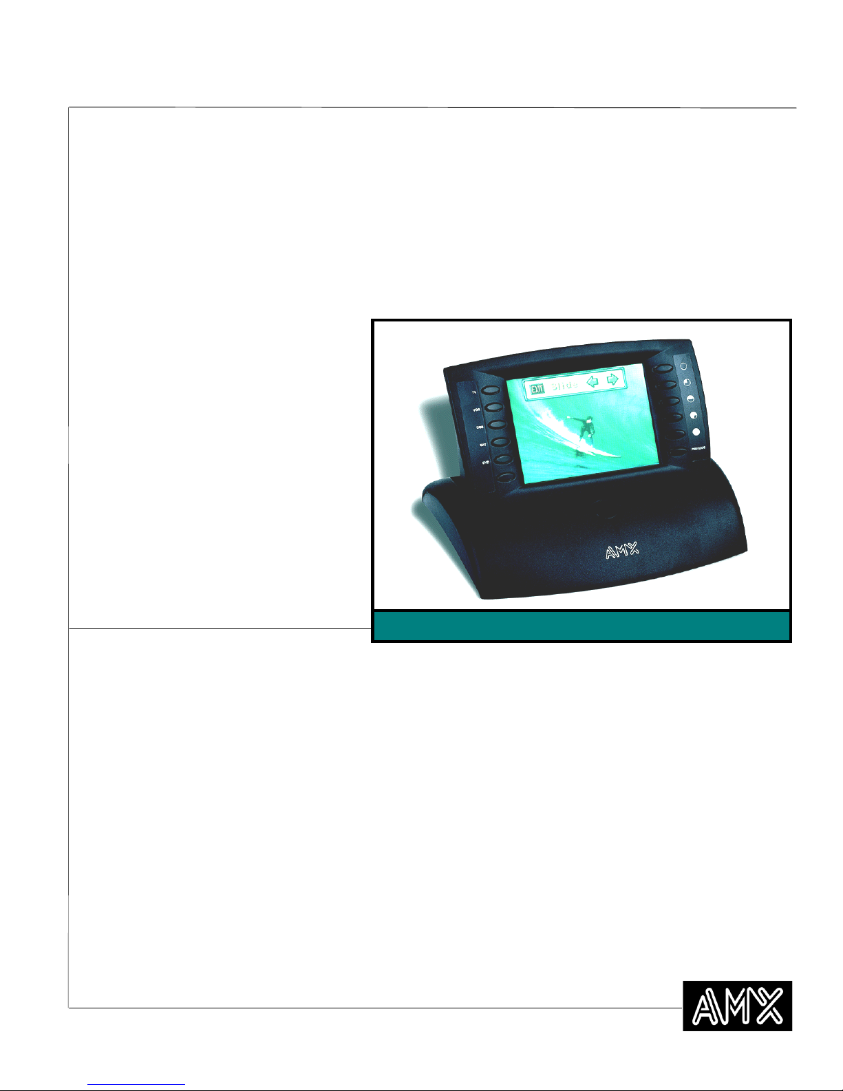
Figure 1
AXD-MCV/PB TiltScreen
Note
Decor-style (AXD) touch panels consist of a faceplate and
overlay that fit on top of ex-
Overview
The Color Active-Matrix Mini-Touch Panels contain a 5.5" (139.70 mm) 256-color
mini-color liquid crystal display (LCD). The self-contained enclosures use a microprocessor to control a wide range of multimedia equipment. Using the TPDesign3
Touch Panel design program, you create custom pages with buttons, icons, sliders,
bargraphs, time displays, logos, and drawings. Figure 1 shows an AXD-MCV/PB
TiltScreen.
Figure 2 lists the panel types and product names described in this manual.
Introduction 1
Page 10

Figure 2
G3 firmware pages.
sign Program.
Color Mini-Touch Panel types
and product names
Color Mini-Touch Panel types and product names
Non-Video Panels Video Panels
Panel types Standard Pushbuttons Standard Pushbuttons
Decor-style AXD-MCA AXD-MCA/PB AXD-MCV AXD-MCV/PB
TiltScreen AXT-MCA AXT-MCA/PB AXT-MCV AXT-MCV/PB
Rack-mount AXM-MCA AXM-MCA/PB AXM-MCV AXM-MCV/PB
UniMount AXU-MCA AXU-MCA/PB AXU-MCV AXU-MCV/PB
Features
The touch panel features include:
5.5" (139.70 mm) diagonal display — 3.05" x 4.06" (77.5 mm x 103.1 mm)
•
HW LCD
256-color active-matrix mini-touch-sensitive LCD
•
320 x 240 pixel (HV) screen resolution
•
512 KB of base memory
•
An angle-adjustable TiltScreen panel for personal viewing convenience
•
Note
TPDesign3 is used to convert
G2 or lower panel pages into
Note
Characters for middle-eastern
languages such as Arabic are
not supported within the
Unicode fonts because they
are bi-directional. Buttons
with Unicode fonts can only
be created and edited using
TPDesign3 Touch Panel De-
Decor-style touch panels provide a secured faceplate to prevent tamper-
•
ing
12 programmable pushbuttons (six on each side)
•
512 KB of memory
•
Microsoft
•
Panel programming, pages, and drawings are uploaded and downloaded
•
using TPDesign (Windows
®
mouse compatible (UniMount and rack-mount models)
®
) 16-bit or TPDesign3 (Windows) 32-bit touch
panel design programs
PAL- , SECAM-, and NTSC- compatible video input port (optional)
•
Internal four-pin header for mouse control (UniMount and rack-mount
•
models only)
Unicode
•
®
character support for far-eastern languages such as Chinese
2 Introduction Color Active-Matrix LCD Mini-Touch Panels
Page 11
Color Active-Matrix LCD Mini-Touch Panels
AXU-MCA/PB
(optional)
AXlink cable
Central Controller (rear)
Television
VCR
Lighting
Camera
<<<< Factory-installed connection
Figure 3
Touch Panel application
Sample AXU-MCA/PB Mini-
Related AMX Instruction Manuals
These instruction manuals contain additional information that relates to the Color Active-Matrix LCD Mini-Touch Panels.
TPDesign3 Touch Panel Program
•
WAVE 2-Way Wireless Accessories and Adapters for Touch Panels
•
SmartPacks for TiltScreen Touch Panels
•
AXCESS Programming Language
•
OpenAXCESS Configuration and Diagnostic Program
•
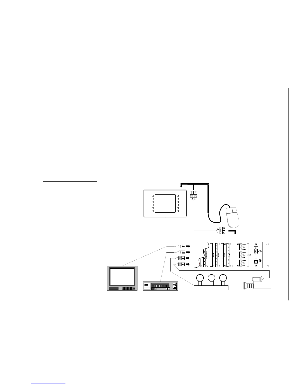
Sample Product Application
The mini-touch panels control a wide variety of equipment connected to the AXCESS
Central Controller. Figure 3 shows a sample AXU-MCA/PB Mini-Touch Panel and
Central Controller configuration.
Serial mouse
Note
The mouse can be used to
design touch panel pages and
then be removed before installation.
Introduction 3
Page 12

What’s in this Manual
This manual contains these sections:
Installing Mini-Touch Panels Describes installing, wiring, and cleaning
•
the mini-touch panels.
Touch Panel Basics Describes the basics of the touch panel operating
•
system, button types, messages, and editor operations.
Designing Touch Panel Pages Describes creating touch panel pages,
•
buttons, joysticks, and bargraphs.
Touch Panel Program Reference Describes all touch panel operations.
•
AXCESS Programming Describes the AXCESS programming commands
•
that are used to program touch panel functions and generate feedback to a
Central Controller.
Replacing the Lithium Batteries Describes replacing the lithium bat-
•
teries in the touch panel.
Upgrading from G2 to G3 Firmware Describes upgrading the touch
•
panel firmware.
Memory Upgrade Describes upgrading the memory ICs (Integrated Cir-
•
cuits) in the touch panel.
Color Guidelines Describes methods you can use to choose the best Mini-
•
Touch Panel colors.
Specifications Describes the physical and operating characteristics of the
•
touch panels.
Contacting AMX Sales/Technical Support Identifies contact informa-
•
tion for AMX technical support and technical publications, such as phone
numbers, e-mail addresses, and internet locations.
What’s New
New information added to this manual includes:
Installing Decor-style touch panels
•
• Touch panel system page and menu illustrations
• Upgrading the Firmware
• Contacting AMX Sales/Technical Support
Revisions are identified with vertical margin bars as shown next to this paragraph.
4 Introduction Color Active-Matrix LCD Mini-Touch Panels
Page 13

Color Active-Matrix LCD Mini-Touch Panels
Installing Mini-Touch Panels
Overview
This section describes mounting, wiring, and cleaning the mini-touch panels.
Mounting information includes the cutout dimensions necessary to install the different panel types into various surfaces. The wiring guidelines subsection includes instructions about preparation, length, and connector pinouts.
Mounting the Mini-Touch Panels
The following paragraphs describe mounting the Decor, UniMount and rack-mount
touch panels. TiltScreen touch panels can be placed on any flat surface.
UniMount- / Decor-style panels with low-profile Back Boxes
These instructions describe installing the UniMount- / Decor-style touch panels listed
in Figure 4.
Figure 4
UniMount- / Decor-style touch
panels
UniMount- / Decor-style touch panels
UniMount Decor-style
AXU-MCA (/PB) AXD-MCA (/PB)
AXU-MCV (/PB) AXD-MCV (/PB)
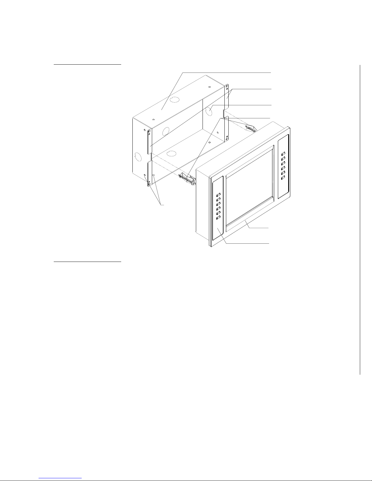
Figure 5 shows a sample AXU-MCA (/PB) and low-profile Back Box.
Installing Mini-Touch Panels 5
Page 14
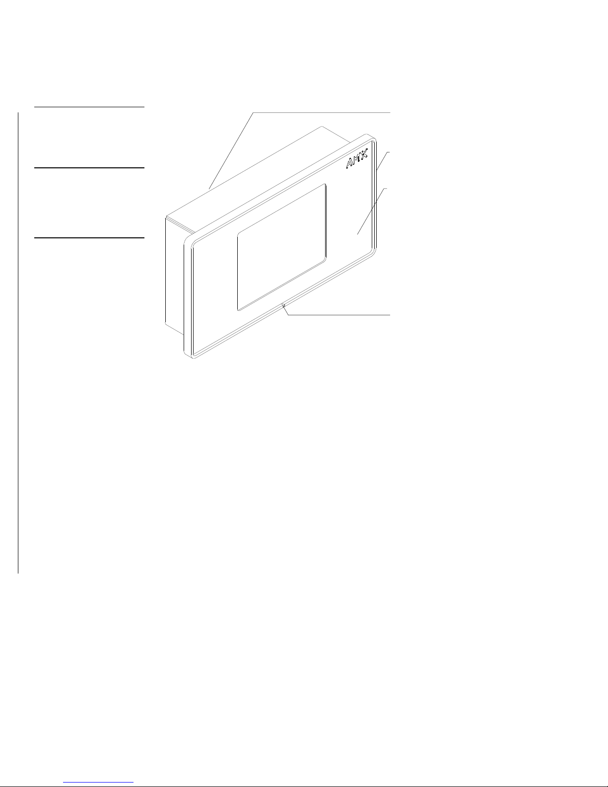
Figure 5
file Back Box
slot located at the bottom.
is called the faceplate.
AXU-MCA (/PB) and low-pro-
Low profile Back Box
AXU-MCA bezel
Note
The touch panel must always
be installed with the release
Note
The front cover of a UniMount
touch panel is called the
backing plate. The front cover
of a Decor-style touch panel
Engraved overlay
Release slot
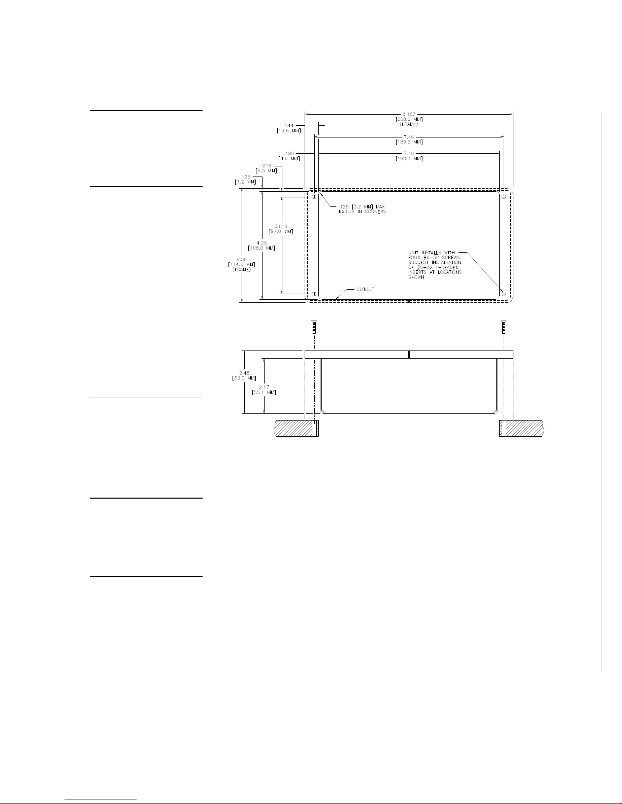
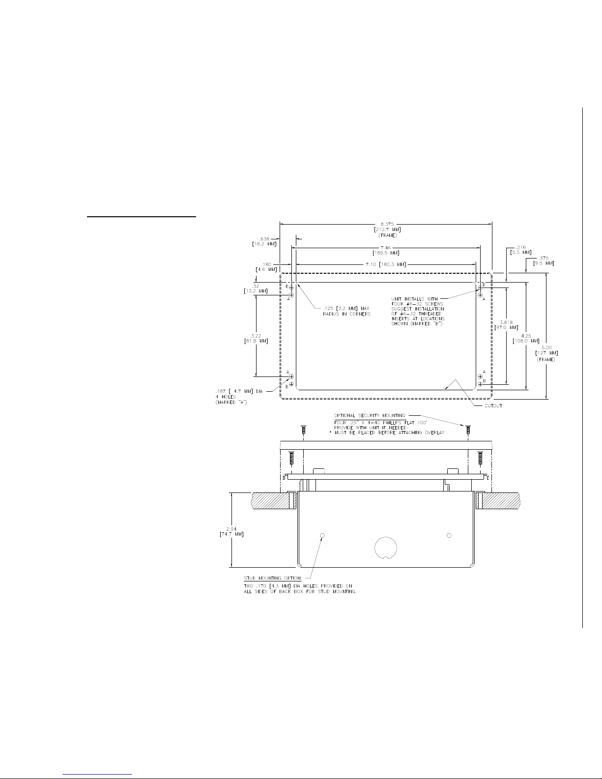
1. For UniMount–style (AXU) touch panels, cut out the surface using the dimen-
sions shown in Figure 6. For Decor-style (AXD) touch panels, cut out the surface
using the dimensions shown in Figure 7.
2. Carefully insert a flat-blade screwdriver into the release slot on the touch panel’s
faceplate and remove the engraved overlay.
3. Place the touch panel into the cutout and mark the screw insert positions as
shown for the UniMount (Figure 6) or the Decor-style panel (Figure 7).
4. Remove the touch panel and drill four #6-32 insert holes. Then, place a threaded
insert into each hole.
5. Disconnect the AXlink connector from the Central Controller.
6. Thread the incoming AXlink and optional RCA video connectors through the
low-profile Back Box.
6 Installing Mini-Touch Panels Color Active-Matrix LCD Mini-Touch Panels
Page 15
Color Active-Matrix LCD Mini-Touch Panels
Figure 6
without removing the overlay.
UniMount (AXU) and lowprofile Back Box cutout dimensions
Note
The touch panel must always
be installed with the release
slot located at the bottom.
Note
Refer to the Wiring the MiniTouch Panels subsection for
de-tailed information.
Note
RCA connectors are used
with video capable mini-touch
panels.
Note
Once attached to the Decorstyle faceplate, the security
screws can’t be replaced
7. Fasten the low-profile Back Box to the surface using the #6-32 machine screws
supplied with the enclosure.
8. Attach the AXlink and optional RCA video connectors to the mini-touch panel.
Refer to Wiring the Mini-Touch Panels for wiring diagrams and pinout descriptions.
9. Test the connection by reconnecting the AXlink connector to the Central Con-
troller and the optional RCA video connectors to the source equipment.
10. Disconnect the above connections until the installation of the panel is complete.
11. Fasten the touch panel and low-profile Back Box to the surface using the #6-32
machine screws supplied with the enclosure.
12. Place the UniMount backing plate or Decor-style faceplate onto the bezel. You
can optionally secure the Decor faceplate to the bezel using the four Phillips flathead security screws.
Installing Mini-Touch Panels 7
Page 16
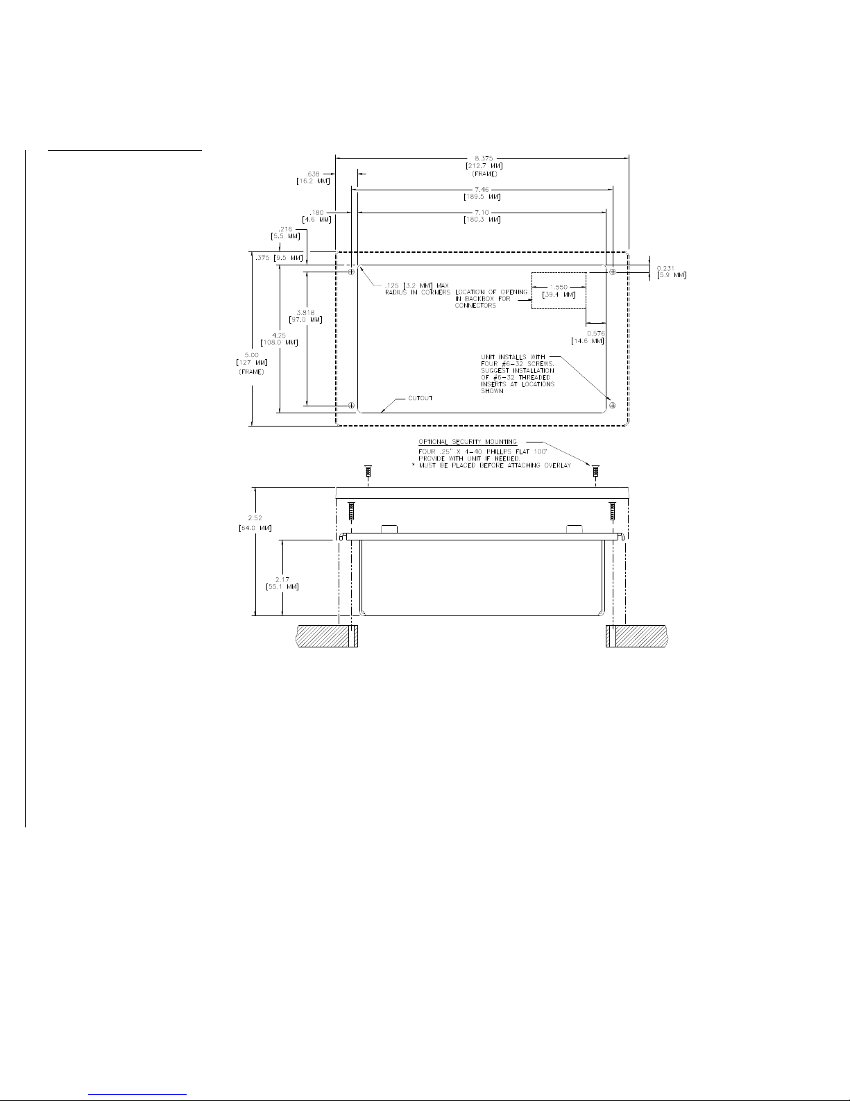
Figure 7
mensions
Decor-style (AXD) and lowprofile Back Box cutout di-
13. Remove the backing from the adhesive tape strips located on the front of the
panel.
14. Press the engraved overlay onto the UniMount or Decor-style faceplate.
15. Reconnect the AXlink and video wiring to the mini-touch panel. Refer to Wiring
the Mini-Touch Panels for wiring diagrams and printout descriptions. The touch
panel will beep when you apply power.
8 Installing Mini-Touch Panels Color Active-Matrix LCD Mini-Touch Panels
Page 17
Color Active-Matrix LCD Mini-Touch Panels
UniMount- / Decor-style panels and BB-MTP UniMount Back Box (solid surfaces)
These instructions describe how to install the UniMount- / Decor-style touch panels
listed in Figure 8.
Figure 8
UniMount- / Decor-style touch
panels
Figure 9
AXD-MCA/PB and BB-MTP
UniMount Back Box (solid
surfaces)
UniMount- / Decor-style touch panels
UniMount Decor-style
AXU-MCA (/PB) AXD-MCA (/PB)
AXU-MCV (/PB) AXD-MCV (/PB)
Figure 9 shows a sample AXD-MCA/PB and BB-MTP UniMount Back Box for solid
surfaces.
BB-MTP UniMount Back Box
enclosure
Solid surface mounting
flanges
Knockout
AXD-MCA/PB
faceplate
Stud mounting
holes
Engraved overlay
Installing Mini-Touch Panels 9
Page 18
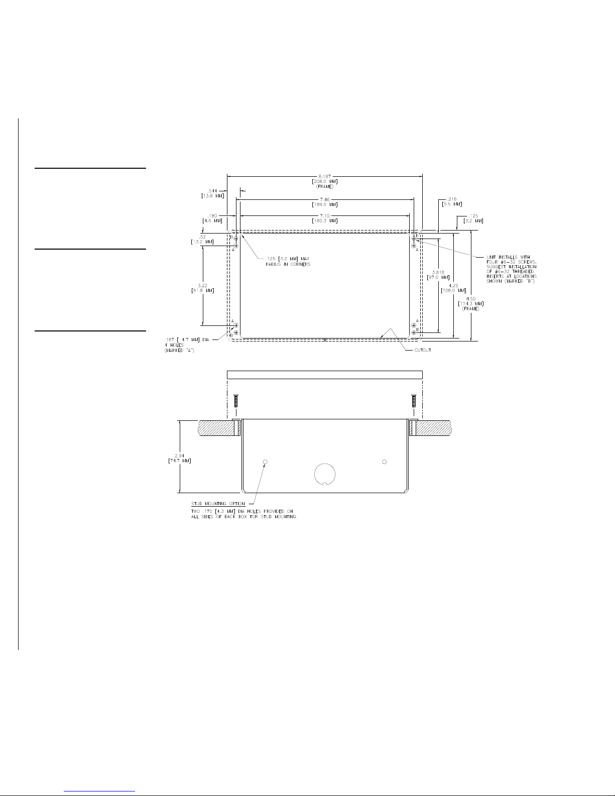
Figure 10
stud mounting holes.
slot located at the bottom.
UniMount (AXU) and) and BBMTP cutout dimensions
Note
The BB-MTP can also be
mounted to wood or metal
studs using the pre-drilled
Note
The touch panel must always
be installed with the release
1. For UniMount–style (AXU) touch panels, cut out the surface using the dimen-
sions shown in Figure 10. For Decor-style (AXD) touch panels, cut out the surface
using the dimensions shown in Figure 11.
2. Carefully insert a flat-blade screwdriver into the release slot on the touch panel’s
bezel and remove the engraved overlay.
3. Lay the touch panel facedown onto a soft cloth and remove the screws from the
low-profile Back Box. Remove the Back Box and discard.
4. Place the BB-MTP into the cutout and mark the threaded insert positions as
shown for the UniMount (Figure 10) or the Decor-style panel (Figure 11).
10 Installing Mini-Touch Panels Color Active-Matrix LCD Mini-Touch Panels
Page 19
Color Active-Matrix LCD Mini-Touch Panels
Figure 11
Decor-style (AXD) and BBMTP cutout dimensions
5. Remove the BB-MTP and drill eight holes as shown for the UniMount
(Figure 10) or the Decor-style panel (Figure 11). Then, place #6-32 threaded inserts into the four holes marked ‘B’ in the cutout dimensions illustration.
6. Disconnect the AXlink connector from the Central Controller and optional video
wiring from the video source. Remove one or more knockouts to accommodate
the wiring as required.
7. Remove one or more knockouts to accommodate the wiring as required.
Installing Mini-Touch Panels 11
Page 20

Note
pinout descriptions.
without removing the overlay.
Refer to Wiring the Mini-
Touch Panel subsection for
8. Thread the incoming AXlink and optional video wiring through the BB-MTP
knockouts.
9. Fasten the BB-MTP to the solid surface using the supplied mounting screws.
10. Connect the AXlink and optional video wiring to the mini-touch panel. Refer to
Wiring the Mini-Touch Panels for wiring diagrams and pinout descriptions.
11. Test the connection by reconnecting the AXlink connector to the Central Con-
troller and optional video wiring to the video source. The panel beeps when you
apply power.
12. Disconnect the above connections until the installation of the panel is complete.
13. Fasten the mini-touch panel to the BB-MTP using the #6-32 screws supplied with
the panel.
14. Place the UniMount backing plate or Decor-style faceplate onto the bezel. You
can optionally secure the Decor faceplate to the bezel using the four Phillips flathead security screws.
15. Remove the backing from the adhesive tape strips on the touch panel.
Note
Once attached to the Decorstyle faceplate, the security
screws can’t be replaced
Figure 12
UniMount- / Decor-style touch
panels
16. Press the engraved overlay onto the UniMount or Decor-style faceplate.
17. Reconnect the AXlink and video wiring to the mini-touch panel. Refer to Wiring
the Mini-Touch Panels for wiring diagrams and printout descriptions. The touch
panel will beep when you apply power.
UniMount- / Decor-style panels and BB-MTP Back Box (plasterboard)
These instructions describe how to install the UniMount- / Decor-style touch panels
listed in Figure 12.
UniMount- / Decor-style touch panels
UniMount Decor-style
AXU-MCA (/PB) AXD-MCA (/PB)
AXU-MCV (/PB) AXD-MCV (/PB)
Figure 13 shows a sample AXD-MCV/PB and BB-MTP UniMount Back Box for plasterboard.
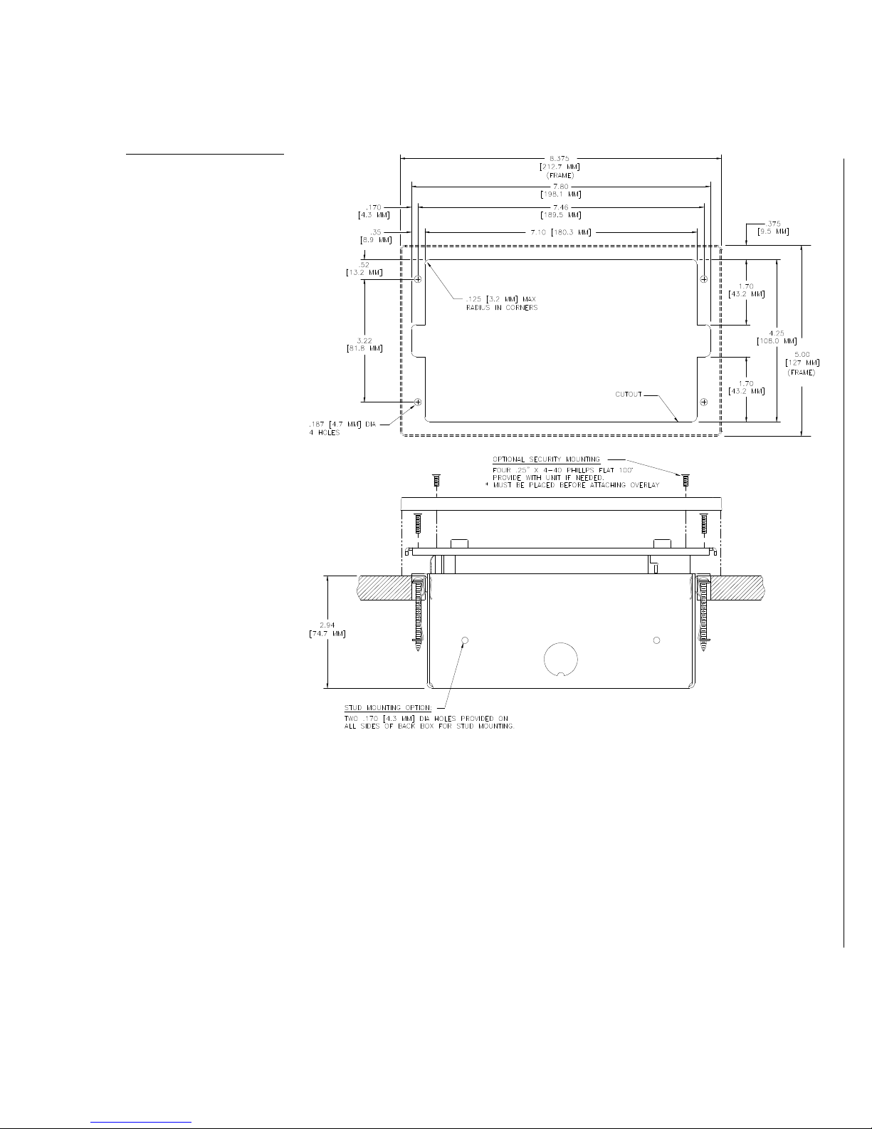
1. For UniMount–style (AXU) touch panels, cut out the surface using the dimen-
sions shown in Figure 14. For Decor-style (AXD) touch panels, cut out the surface
using the dimensions shown in Figure 15.
12 Installing Mini-Touch Panels Color Active-Matrix LCD Mini-Touch Panels
Page 21
Color Active-Matrix LCD Mini-Touch Panels
Figure 13
slot located at the bottom.
AXD-MCV/PB and BB-MTP
UniMount Back Box (plasterboard)
BB-MTP UniMount Back
Box enclosure
Plasterboard surface
mounting flanges
Knockout
Expansion clips
Stud
mounting
holes
AXD-MCV/PB
faceplate
Engraved overlay
Note
The touch panel must always
be installed with the release
2. Carefully insert a flat-blade screwdriver into the release slot on the touch panel’s
faceplate and remove the engraved overlay.
3. Lay the touch panel facedown onto a soft cloth and remove the screws from the
low-profile Back Box. Remove the Back Box and discard.
4. Place the BB-MTP into the cutout and mark the threaded insert positions as
shown for the UniMount (Figure 14) or the Decor-style panel (Figure 15).
5. Remove the BB-MTP and drill four #6-32 insert holes. Then, place a threaded in-
sert (or screw anchor) into each hole.
6. Remove the BB-MTP and drill four #6-32 insert holes. Then, place a threaded in-
sert (or screw anchor) into each hole.
7. Disconnect the AXlink connector from the Central Controller and optional video
wiring from the video source.
Installing Mini-Touch Panels 13
Page 22
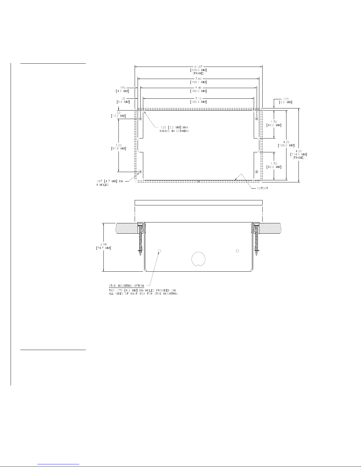
Figure 14
UniMount (AXU) and BB-MTP
cutout dimensions for plasterboard
8. Remove the BB-MTP and drill four #6-32 insert holes. Then, place a threaded in-
sert (or screw anchor) into each hole.
9. Disconnect the AXlink connector from the Central Controller and optional video
wiring from the video source.
Note
Refer Wiring the Mini-Touch
Panel subsection for pinout
descriptions.
14 Installing Mini-Touch Panels Color Active-Matrix LCD Mini-Touch Panels
10. Remove one or more knockouts to accommodate the wiring as required.
11. Thread the incoming AXlink and optional video wiring through the BB-MTP
knockout.
Page 23
Color Active-Matrix LCD Mini-Touch Panels
Figure 15
Decor-style (AXD) and BBMTP cutout dimensions for
plasterboard
12. Fasten the BB-MTP to the plasterboard using the expansion screws supplied with
the enclosure.
13. Connect the AXlink and optional video wiring to the mini-touch panel. Refer to
Wiring the Mini-Touch Panels for wiring diagrams and printout descriptions.
14. Test the connection by reconnecting the AXlink connector to the Central Con-
troller and optional video wiring to the video source. The panel beeps when you
apply power.
15. Disconnect the above connections until the installation of the panel is complete.
Installing Mini-Touch Panels 15
Page 24
16. Fasten the mini-touch panel to the BB-MTP with the #6-32 screws supplied.
without removing the overlay.
17. Place the UniMount backing plate or Decor-style faceplate onto the bezel. You
can optionally secure the Decor faceplate to the bezel using the four Phillips flathead security screws.
Note
Once attached to the Decorstyle faceplate, the security
screws can’t be replaced
Figure 16
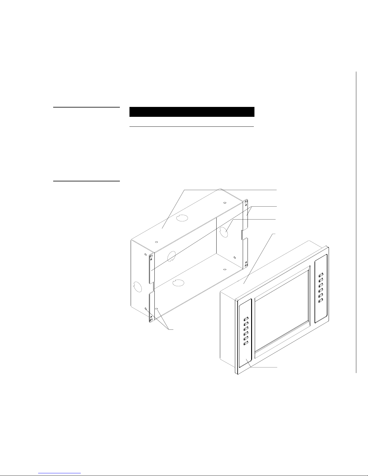
Rack-mount touch panel
Figure 17
AXM-MCA/PB rack mount
18. Remove the backing from the adhesive tape strips.
19. Press the engraved overlay onto the UniMount or Decor-style faceplate.
20. Reconnect the AXlink wiring to the Central Controller, and video wiring to the
video source. The mini-touch panel will beep when you apply power.
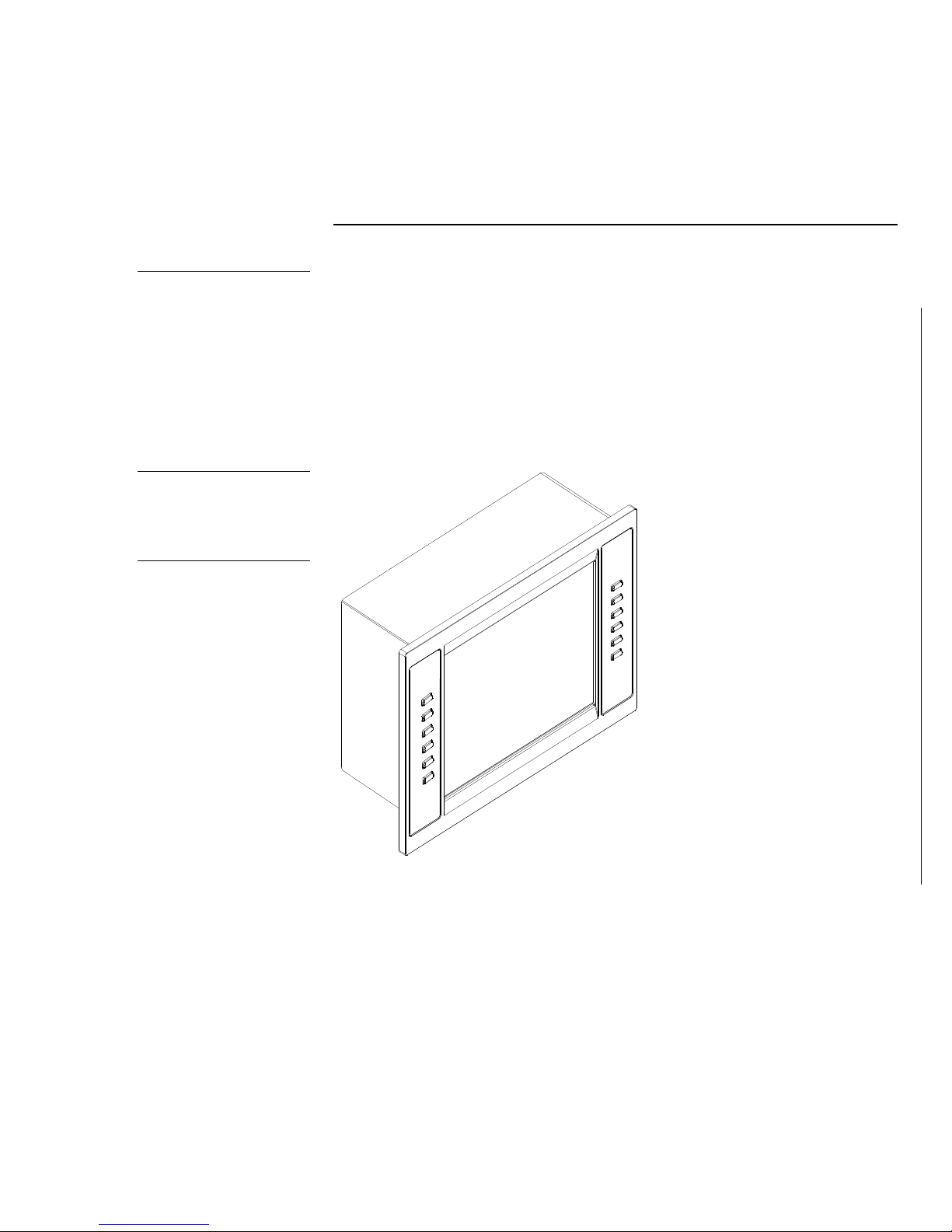
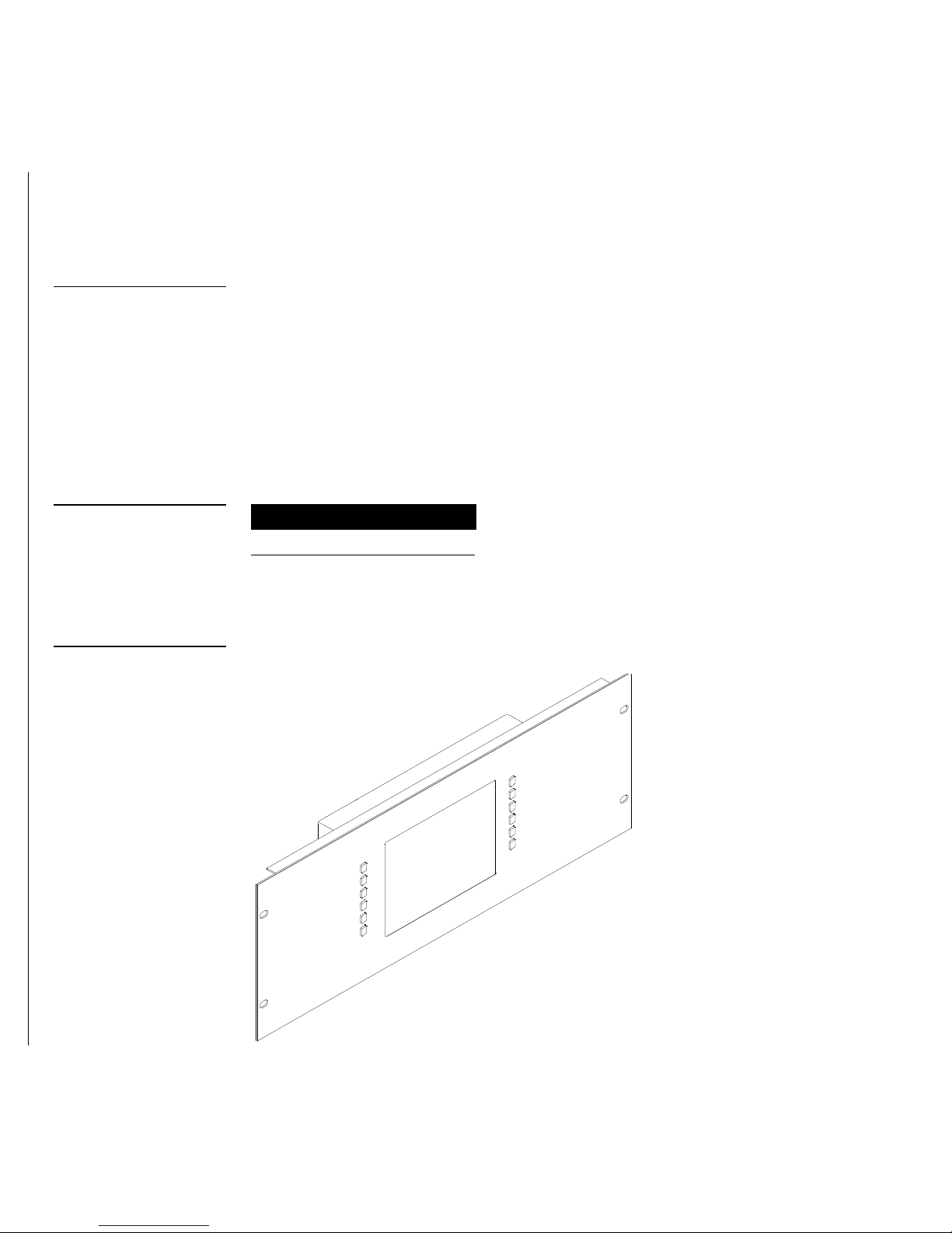
Rack-mount panels
These instructions describe installing the rack-mounted touch panels listed in
Figure 16.
Rack-mount touch panel
UniMount
AXM-MCA (/PB)
AXM-MCV (/PB)
Figure 17 shows an AXM-MCA/PB rack-mount touch panel.
16 Installing Mini-Touch Panels Color Active-Matrix LCD Mini-Touch Panels
Page 25
Color Active-Matrix LCD Mini-Touch Panels
1. Thread the incoming AXlink and video wiring through the opening in the
AXlink
Video In
equipment rack.
2. Disconnect the AXlink connectors from the Central Controller and optional video
wiring from the video source.
3. Connect the AXlink and video wiring to the mini-touch panel circuit card. Refer
to Wiring the Mini-Touch Panels for wiring diagrams and pinout descriptions.
4. Insert the touch panel into the equipment rack. Line up the top-left and bottom-
right screw holes and start the #6-32 screws. Then, start screwing the bottom-left
then top-right screws. Tighten all the screws after you start all the screws.
5. Connect both the AXlink wiring to the Central Controller and video wiring to the
video source. The mini-touch panel will beep when you apply power.
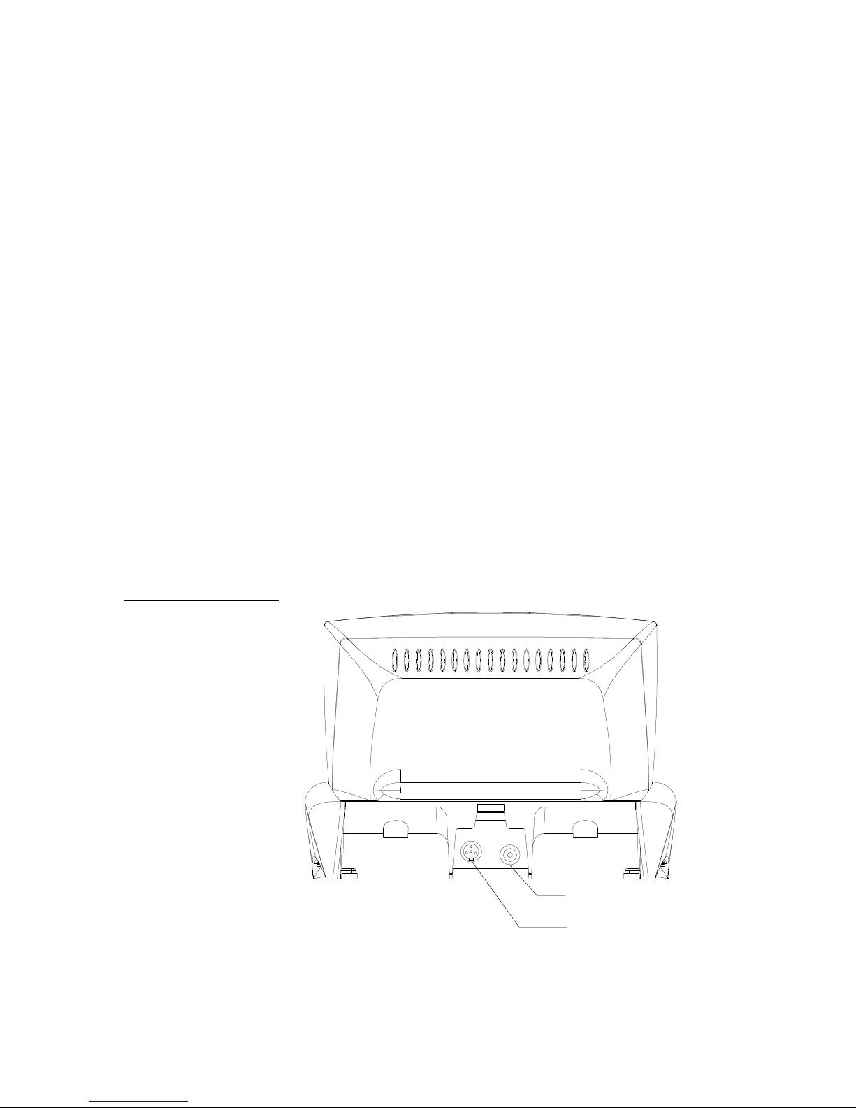
Wiring the Mini-Touch Panels
The Mini-TiltScreen Touch Panels use a mini-XLR connector to supply power / data
communications, and an optional RCA connector to display PAL-, SECAM-, or
NTSC- compatible video. The UniMount and rack-mount mini-touch panels use a
four-pin AXlink connector for power and data, and an optional RCA connector to
display PAL- or NTSC-compatible video. Figure 18 shows the rear panel AXlink and
optional RCA connectors on the Mini-TiltScreen Touch Panels.
Figure 18
Mini-TiltScreen Touch Panel
connectors (rear view)
Rear view
RCA video connector (optional)
Mini-XLR four-pin AXlink and
power connector
Installing Mini-Touch Panels 17
Page 26
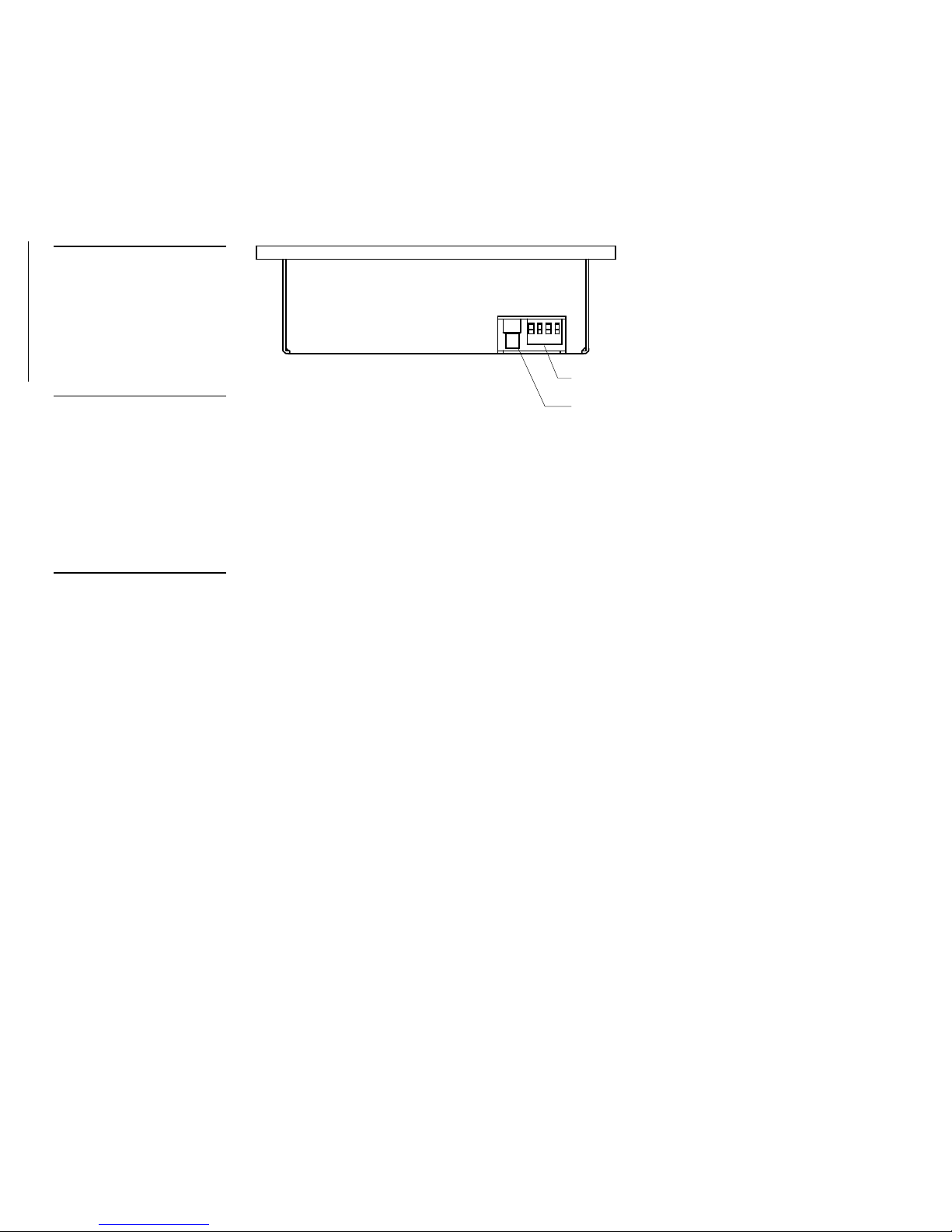
Figure 19
after installation is complete.
the connector.
UniMount- / Decor-style minitouch panel connectors (top
view)
Figure 19 shows the rear panel AXlink and optional RCA connector on the rackmount mini-touch panel.
Caution
Do not connect power to the
touch panel until the wiring is
complete. If you are using a
12 VDC power supply, apply
power to the touch panel only
Caution
Do not over-torque the
screws. Doing so can bend
the seating pin and damage
Top view
Four-pin AXlink connector
RCA video connector (optional)
Preparing captive wires
You will need a wire stripper, soldering iron, and flat-blade screwdriver to prepare
and connect the captive wires.
1. Strip 0.25 inch of wire insulation off all wires and apply a light coat of solder to
the ends using a soldering iron.
2. Insert each wire into the appropriate opening on the connector according to the
wiring diagrams and connector types described in this subsection.
3. Turn the flat-blade screws clockwise to secure the wire in the connector.
Wiring guidelines
The touch panels require 12 VDC power to operate properly. The Central Controller
supplies power via the AXlink cable or external 12 VDC power supply. The maximum wiring distance between the Central Controller and touch panel is determined
by power consumption, supplied voltage, and the wire gauge used for the cable.
Figure 20 lists wire sizes and the maximum lengths allowable between the mini-touch
panel and Central Controller. The maximum wiring lengths for using AXlink power
are based on a minimum of 13.5 volts available at the Central Controller’s power
supply. For more information on power requirements, see the Specifications section.
18 Installing Mini-Touch Panels Color Active-Matrix LCD Mini-Touch Panels
Page 27
Color Active-Matrix LCD Mini-Touch Panels
1
234
1 - GND (-)
3 - AXP
2 - AXM
4 - PWR (+)
GND (-)
2
1
PWR (+)
AXM
AXP
3
4
Control system
4-pin mini-XLR
connector
Figure 20
of each device.
Wiring guidelines
Note
Refer to the Specifications
section for information on the
maximum power consumption
Figure 21
Wiring guidelines for MCA
(750 mA)
Wire-size Maximum wiring
length
18 AWG 156.5 feet (44.70 m) 18 AWG 146.7 feet (44.71 m)
20 AWG 99. feet (30.18 m) 20 AWG 92.8 feet (28.29 m)
22 AWG 61.7 feet (18.80m) 22 AWG 57.9 feet (17.65 m)
24 AWG 38.9 feet (11.86 m) 24 AWG 34.5 feet (10.52 m)
Wiring guidelines for MCV
(800 mA)
Wire-size Maximum wiring
length
If you install the mini-touch panel farther from the Central Controller than recommended in Figure 20, connect an external 12 VDC power to the touch panel as shown
in the wiring diagrams and pinout descriptions in this section.
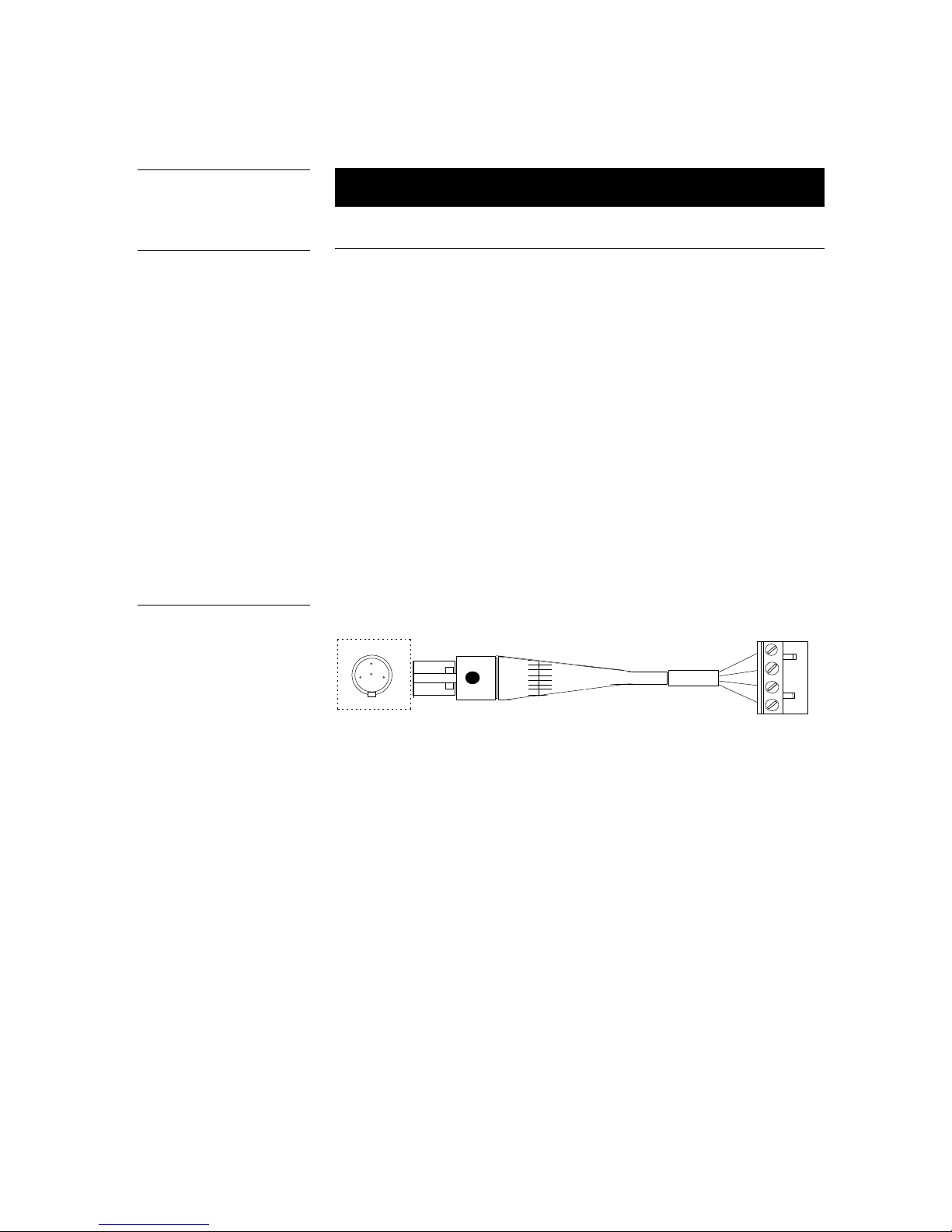
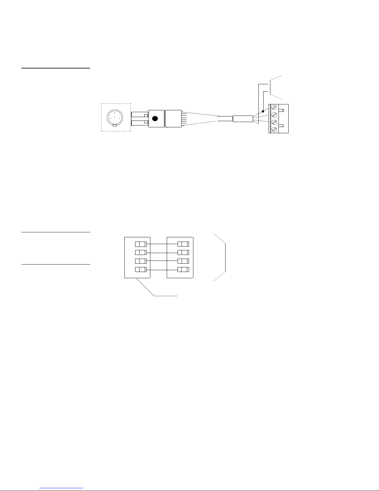
Using the AXlink mini-XLR connector for data and power (TiltScreen)
Connect the Central Controller’s AXlink connector to the mini-XLR connector (male)
on the rear panel of the TiltScreen touch panel for data and 12 VDC power as shown
in Figure 21.
Mini-XLR connector to Central
Controller wiring diagram
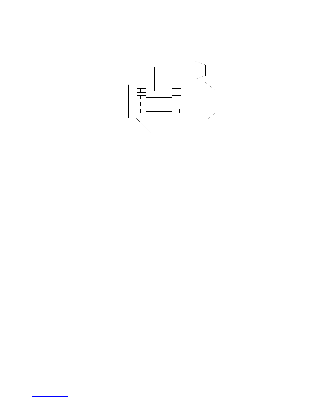
Using the AXlink mini-XLR connector and external 12 VDC power supply
(TiltScreen)
Connect the Central Controller’s AXlink connector to the mini-XLR connector and
external 12 VDC power supply to the rear panel of the mini-touch panel as shown in
Figure 22.
Installing Mini-Touch Panels 19
Page 28
1
234
1 - GND (-)
3 - AXP
2 - AXM
4 - PWR (+)
4-pin mini-XLR
connector
PWR (+)
Control system
GND (-)
2
1
PWR (+)
AXM
AXP
3
4
GND (-)
12 VDC power supply
PWR (+)
AXM
AXP
GND (-)
AXlink connector
Central Controller
PWR (+)
AXM
AXP
GND (-)
Figure 22
gram
AXlink wiring diagram
before wiring the touch panel.
Mini-XLR connector to external 12 VDC power supply,
and Central Controller wiring
dia
Figure 23
Using the AXlink connector for data and power
Connect the Central Controller’s AXlink connector to the AXlink connector (male) on
the rear panel of the touch panel for data and 12 VDC power as shown in Figure
23.
Caution
If you are using power from
AXlink, disconnect the wiring
from the Central Controller
UniMount or rack-mount
Using the AXlink four-pin connector and external 12 VDC power supply
Connect the Central Controller’s AXlink connector to the AXlink connector on the
rear panel of the touch panel as shown in Figure 24.
20 Installing Mini-Touch Panels Color Active-Matrix LCD Mini-Touch Panels
Page 29
Color Active-Matrix LCD Mini-Touch Panels
PWR (+)
AXM
AXP
GND (-)
PWR (+)
AXM
AXP
GND (-)
AXlink connector
Central Controller
12 VDC power supply
PWR (+)
GND (-)
Figure 24
AXlink and external 12 VDC
power supply, and Central
Controller wiring diagram
UniMount or rack-mount
Use a 12 VDC power supply when the distance between the Central Controller and
mini-touch panel exceeds the limits described in Figure 20. Make sure to connect only
the GND wire on the AXlink connector when using a 12 VDC power supply. Do not
connect the PWR wire to the AXlink connector’s PWR (+) terminal.
Cleaning the Touch Panel LCD
You should clean the LCD after installing the touch panel:
1. Disconnect all connectors from the touch panel.
2. Using one of two cotton cloths, spray a small amount of cleaning solution con-
sisting of 50% isopropyl alcohol and 50% water onto the cloth.
3. Wipe the touch overlay. Then wipe dry with the other clean cloth.
4. Reconnect all connectors to the touch panel.
Installing Mini-Touch Panels 21
Page 30

22 Installing Mini-Touch Panels Color Active-Matrix LCD Mini-Touch Panels
Page 31

Figure 25
Sample touch panel page
Touch Panel Basics
Overview
This section contains descriptions and illustration examples of touch panel pages
(Figure 25), buttons, message bars, and keypads. You can use the touch panel’s onboard editor or the TPDesign3 software program to create custom pages.
Color Active-Matrix LCD Mini-Touch Panels Touch Panel Basics 23
Touch Panel Pages
You create buttons, bargraphs, sliders, and drawings when the touch panel editor is
active. The number of objects depends on the type and quantity of external devices
you want to control with the touch panel and Central Controller. When you create
multiple pages, you must link them with buttons. Figure 26 shows how five touch
panel pages are linked to the Main page. Each page has a button that flips to the next
page, and one that flips back to the previous page.
Page 32

Main Page
Page
Page 2
Main
Page 3
Page 1
Page 4
Page 2
Page 5
Page 3
Main
Page 4
Page 1
Figure 26
linked buttons
Touch Panel pages with
Setup
Page 1
Page 2
Page 3
Page 4
Page 5
Standard Buttons
Standard buttons types are rectangles, rectangle variations, and other geometric
shapes that you can create with the touch panel editor. Buttons are set with attributes,
which means there is feedback for the Central Controller when you touch the button.
General Buttons
General buttons are part of the mini-touch panel program and cannot be changed.
You use general buttons to specify panel communication parameters and create or
revise pages. Button examples include selection buttons, information buttons, adjustment buttons, and operation bars. Each type of General button is described in the
following paragraphs.
Selection buttons
Selection buttons (Figure 27) appear on touch panel pages and set communication parameters.
24 Touch Panel Basics Color Active-Matrix LCD Mini-Touch Panels
Page 33

Figure 27
changed.
Information button example
Adjustment button example
Selection button example
Note
These button types will be
displayed in black and yellow
to indicate that they are only
for information and can’t be
Figure 28
Figure 29
Information buttons
Information buttons are read-only buttons that contain serial numbers, firmware versions, and hardware status information. Figure 28 shows the serial number information button in the Setup page.
Adjustment buttons
You can use the UP and DN buttons to set adjustment buttons. The adjustment button example in Figure 29 sets the baud rate for the RS-232 connector on the touch
panel.
Color Active-Matrix LCD Mini-Touch Panels Touch Panel Basics 25
Keypad buttons
The keypad button opens a keypad (Figure 30) so you can enter a password or value
assignment. All buttons on the keypad are interactive except for the entry display.
Page 34

Figure 30
Decision button example
Operation bar example
Keypad entry (0 - 9)
CLEAR – Resets the entry to 0
ENTER – Processes the entry
Keypad example
Figure 31
Entry display
Decision buttons
Decision buttons (Figure 31) appear when an operation has two options and requires you to verify the action before it is performed.
Status buttons
Figure 32
Status button example
Figure 33
Status buttons (Figure 32) appear when you try to perform operations that do not
function correctly.
NO COMMUNICATION
TOUCH SCREEN TO CONTINUE
Operation bars
Operation bars (Figure 33) appear when you try to perform an action selected from
either the BUTTON or PAGE pull-down menus.
26 Touch Panel Basics Color Active-Matrix LCD Mini-Touch Panels
Page 35

Designing Touch Panel Pages
Main page.
Overview
These step-by-step instructions describe creating touch panel pages, buttons, joysticks, bargraphs, and setting page color attributes. For in-depth information on all
the operations available on the touch panel, read through the Touch Panel Program
Reference section to learn about all operations and techniques available to design
touch panel pages.
Activating the Edit Button
Note
If you have a pre-programmed
panel, you may not see the
Figure 34
Main page
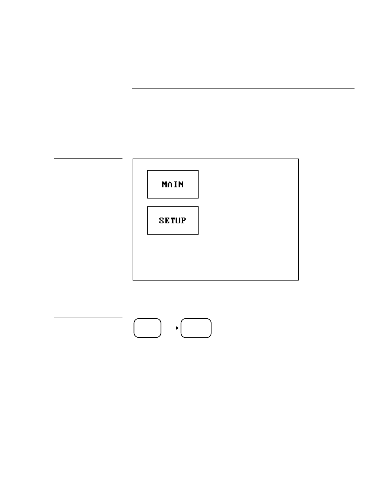
Before designing a touch panel page, activate the EDIT button which contains options
to add and configure touch panels and buttons. When powering up the mini-touch
panel, the first page is the Main page shown in Figure 34. Refer to the Edit button and
Go to subsections within the Touch Panel Program Reference section if the Main page
does not appear.
Color Active-Matrix LCD Mini-Touch Panels Designing Touch Panel Pages 27
Page 36
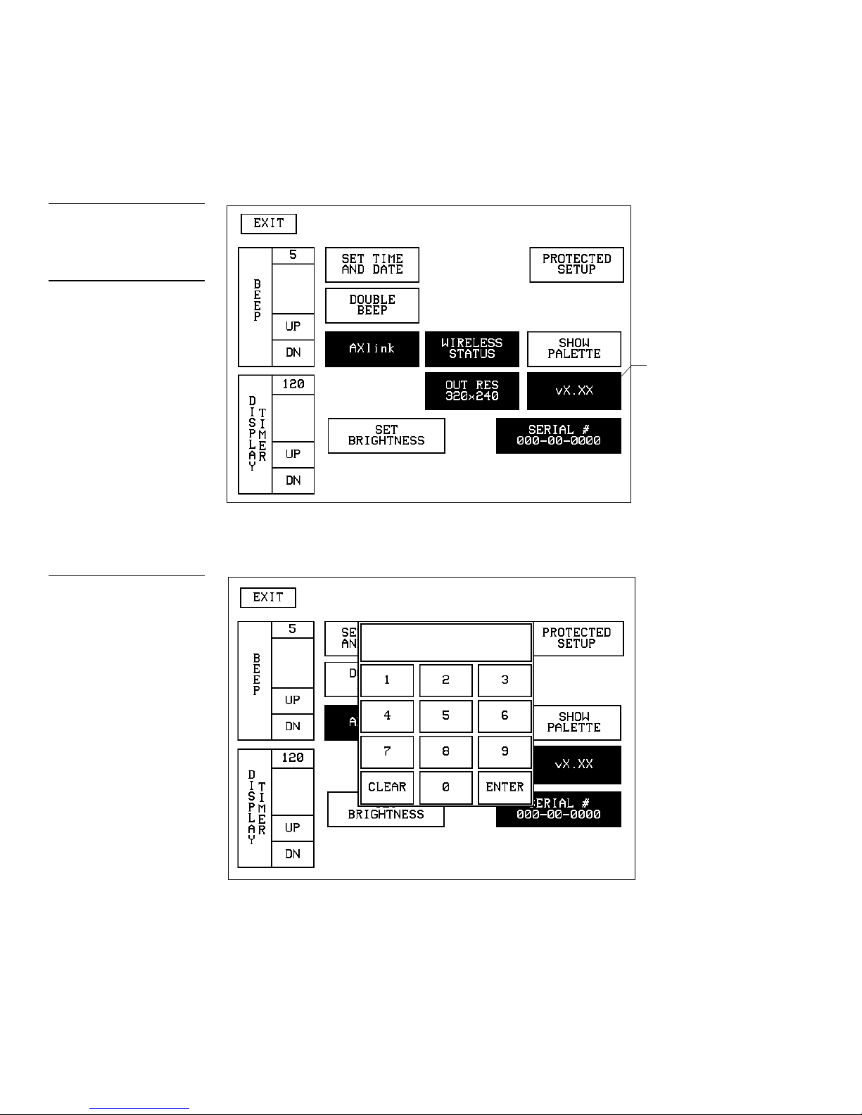
Figure 35
Setup page
tons.
keypad
Note
Color Active-Matrix mini-touch
panel information buttons are
displayed with a black fill.
These buttons can’t be altered and are only used to
display information. Examples
of these are the AXlink,
OUTPUT RESOLUTION,
vX.XX, and SERIAL # but-
1. Press SETUP in the Main page to open the Setup page shown in Figure 35.
Firmware
version
2. Press PROTECTED SETUP to open the password keypad shown in Figure 36.
Figure 36
Setup page and password
28 Designing Touch Panel Pages Color Active-Matrix LCD Mini-Touch Panels
Page 37
Note
returned to the current page.
active EDITOR button
If you press ENTER after
typing in an incorrect password, you are immediately
Figure 37
Protected Setup page with the
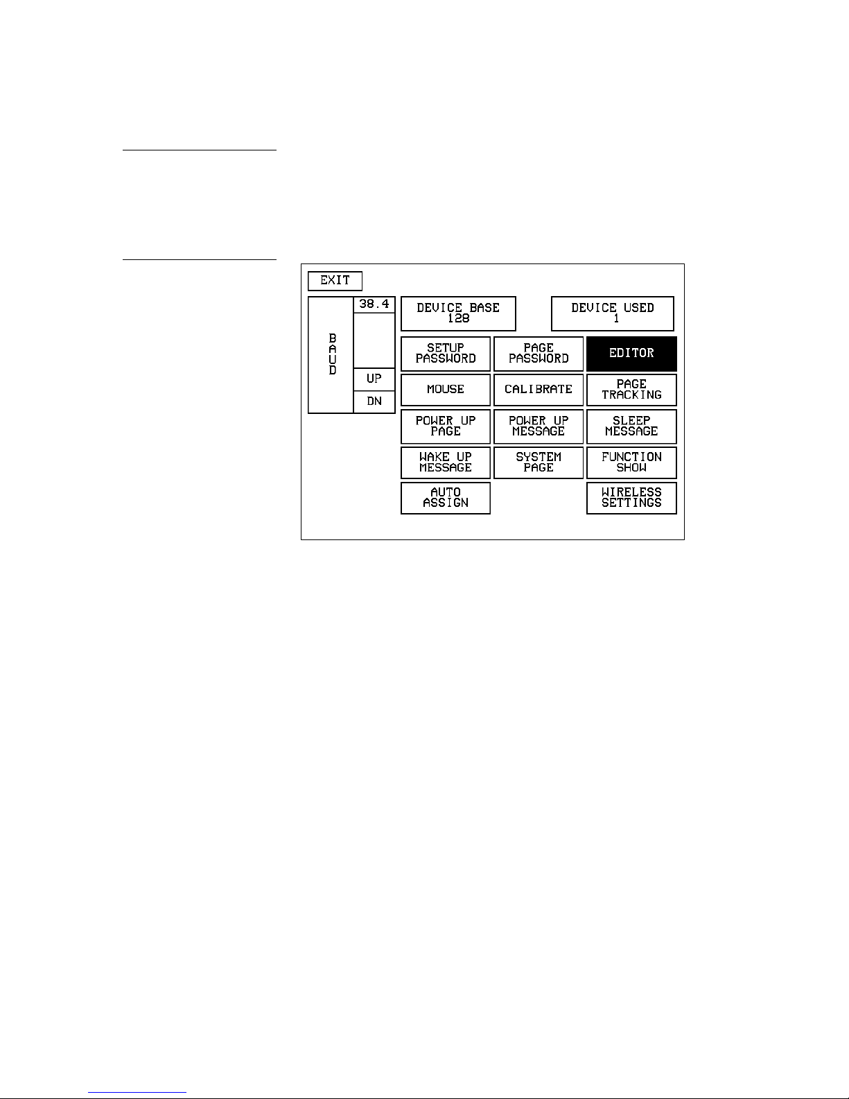
3. Enter 1988 in the keypad and press ENTER to open Protected Setup page
(Figure 37). For information on changing the password, refer to the Touch Panel
Program Reference section. If you enter a wrong number, press CLEAR and re-
enter the number.
4. Press EDITOR to enable the Edit mode. The EDITOR button is highlighted when
enabled (Figure 37).
5. Press EXIT to close the Protected Setup page and return to the Setup page in Edit
mode.
6. Press EXIT again to return to the Main page. The EDIT button appears at the top
of the Main page indicating that Edit mode is active (Figure 38).
Color Active-Matrix LCD Mini-Touch Panels Designing Touch Panel Pages 29
Page 38
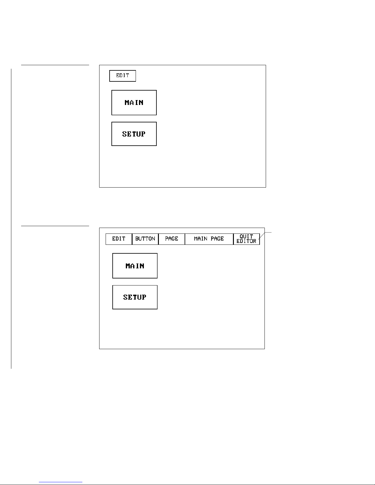
Figure 38
Main page and Edit bar
Main page and EDIT button
7. Press the EDIT button to open the Edit bar. BUTTON and PAGE in the Edit bar
(Figure 39) are used to design and modify button and page settings.
Figure 39
Edit bar
30 Designing Touch Panel Pages Color Active-Matrix LCD Mini-Touch Panels
Page 39

Figure 40
PAGE menu
Creating a Page
Use the PAGE menu in the Edit bar to create a touch panel page.
Adding a page
1. Press PAGE on the Edit bar to open the PAGE menu shown in Figure 40.
2. Press ADD to open the keyboard (Figure 41) and enter the name for the new
touch panel page.
Color Active-Matrix LCD Mini-Touch Panels Designing Touch Panel Pages 31
Page 40

Figure 41
Keyboard
tons.
Note
Page naming does not allow
you to change the font type,
as is only available for but-
Figure 42
3. Enter NEW PAGE (Figure 42) using the keyboard. A page name can be up to 20
characters.
Keyboard: NEW PAGE
4. Press EXIT CHANGE to add NEW PAGE to touch panel memory, close the key-
board, and open the new page.
32 Designing Touch Panel Pages Color Active-Matrix LCD Mini-Touch Panels
Page 41

Figure 43
Color palette
the incoming video signal.
Note
The VIDEO PAGE button on
the color palette will allow the
entire background to display
Setting the page color
1. Press the EDIT button to open the Edit bar onto the newly created page.
2. Press PAGE on the Edit bar to open the PAGE menu.
3. Press PAGE COLOR to open the color palette shown in Figure 43.
4. Select a page color from the color palette. The page automatically changes to the
selected color.
Creating a Button
Use the BUTTON menu in the Edit bar to create touch panel buttons.
Adding a button
1. Press EDIT to open the Edit bar.
2. Press BUTTON on the Edit bar to open the BUTTON menu shown in Figure 44.
Color Active-Matrix LCD Mini-Touch Panels Designing Touch Panel Pages 33
Page 42

Height
Touch Point
Figure 44
ADD BUTTON operation bar
Add a button example
tion.
BUTTON menu
Figure 45
3. Press ADD to open the ADD BUTTON operation bar (Figure 45).
Figure 46
Note
Repeat steps 4 and 5 to add
multiple buttons. You have to
close the ADD BUTTON operation bar before you can
continue with another opera-
4. Touch and drag your finger horizontally down the LCD screen to create the but-
ton as shown in Figure 46. The first touch point is the upper-left corner of the
button.
Width
5. Release your finger from the panel to store the button dimensions into panel
memory.
6. Press EXIT to close the Edit bar.
34 Designing Touch Panel Pages Color Active-Matrix LCD Mini-Touch Panels
Page 43

resize.
Figure 47
bar
buttons.
RESIZE BUTTON operation
Resizing a button
1. Press EDIT to open the Edit bar.
2. Press BUTTON on the Edit bar to open the BUTTON menu.
3. Press RESIZE to open the RESIZE BUTTON operation bar (Figure 47).
4. Push the edge of the button, and drag your finger horizontally across the screen
and down to resize the button (Figure 48).
Figure 48
Resizing a button
Note
The same steps apply to setting properties for external
Touch any edge or
corner and drag to
5. Release your finger from the panel to store the button dimensions into the panel
memory.
6. Press EXIT in the Edit bar.
Button Properties
Use the PROPERTIES option of the BUTTON menu in the Edit bar to set button borders, page flips, button colors for channel on and off conditions, and channel and
variable text codes.
Setting the button properties
Color Active-Matrix LCD Mini-Touch Panels Designing Touch Panel Pages 35
1. Press EDIT to open the Edit bar.
2. Press BUTTON on the Edit bar to open the BUTTON menu options.
3. Press PROPERTIES to open the PROPERTIES operation bar shown in Figure 49.
Page 44

Figure 49
PROPERTIES operation bar
Button Properties page
GENERAL type button.
Figure 50
Note
The contents of the Button
Properties page will change
according to the type of button selected. The example
shown here is for a
4. Press the button you just added to open the Button Properties page shown in
Figure 50. This page lists the properties for the active button.
Setting the button type
1. Press BUTTON TYPE in the Button Properties page. This opens the BUTTON
TYPE menu, shown in Figure 51. Press MORE at the bottom of the first page of
Button Types options to view the next page of options. Press PREV to view the
first page.
36 Designing Touch Panel Pages Color Active-Matrix LCD Mini-Touch Panels
Page 45

Figure 51
pages
Button Types menu
2. Select a button type for the selected button to open the associated Button Proper-
ties page for the selected button type. Each button type has its own Button Properties page with settings specific to the button type. For example, select
GENERAL from the menu to set the selected button as a general button. This
opens the GENERAL Button Properties page, shown in Figure 50.
Figure 52
BUTTON BORDER menu
Setting the button border
1. Press BORDER in the Button Properties page to open the BUTTON BORDER
pages shown in Figure 52. These menu pages appear individually and can all be
viewed by using the MORE and PREV buttons.
Color Active-Matrix LCD Mini-Touch Panels Designing Touch Panel Pages 37
Page 46

2. Press 3D RECTANGLE 1 to set the button border to 3D RECTANGLE 1 style and
129, 130, and 131.
CHANNEL code buttons
previous value.
255.
129, 130, and 131.
return to the Button Properties page. The BORDER button in the Button Properties page changes to show the active border type. In this case, the button changes
to the 3D-rectangle border.
Note
If DEVICE USED is set to 4
and Base Device Number is
128, the Central Controller
recognizes bus devices 128,
Figure 53
Note
The panel will not allow you to
enter a device number greater
than the DEVICE USED without first displaying a decision
box. This box asks you to decide whether you accept the
new selection or default to the
Note
The channel code for nonactive buttons is 0 and for
active buttons is 1 through
Setting the channel code
The channel buttons that set the device and button channel codes for the touch panels
are shown in Figure 53. Refer to Figure 159 for more information on DEV and CHAN.
1. Press DEV to open the keypad and set the touch panel’s device number.
2. Enter 1, 2, 3, or 4 in the keypad. The AXCESS software program uses device
codes 1 through 4 to identify the touch panel. Refer to the Touch Panel Program
Reference section for detailed information.
3. Press ENTER to store the device number into memory, close the keypad, and re-
turn to the Button Properties page.
4. Press CHAN to open a keypad and enter a channel value of 1 through 255 in the
keypad. The AXCESS software program uses the channel code number to identify the button and its’ programmed operations.
5. Press ENTER to store the channel number in memory, close the keypad, and re-
turn to the Button Properties page.
Note
If DEVICE USED is set to 4
and Base Device Number is
128, the Central Controller
recognizes bus devices 128,
38 Designing Touch Panel Pages Color Active-Matrix LCD Mini-Touch Panels
Page 47

Figure 54
the previous value.
buttons is 1 through 255.
Flip to page button
Page FLIP type button
VAR TEXT code button
Setting the variable text code
The variable text buttons that set the device and button channel codes for the touch
panels are shown in Figure 54.
Note
The panel will not allow you to
enter a device number greater
than the DEVICE USED without first displaying a decision
box. This box asks you to
decide whether you accept
the new selection or default to
Note
The channel codes for nonactive buttons is 0, and active
Figure 55
1. Press DEV to open a keypad and set the device number.
2. Enter 1, 2, 3, or 4 in the keypad. The AXCESS software program uses device
codes 1 through 4 to identify the touch panel. Refer to the Touch Panel Program
Reference section in this manual for detailed information.
3. Press ENTER to store the device number in memory, close the keypad, and re-
turn to the Button Properties page.
4. Press CHAN to open a keypad and set the channel number.
5. Enter a channel value of 1 through 255 in the keypad. The AXCESS software
program uses the channel code number to identify the button and its operations.
6. Press ENTER to store the channel number into memory, close the keypad, and
return to the Button Properties page.
Setting the page flip
1. Press the left FLIP box in the Button Properties page (Figure 55) to open the
PAGE FLIP TYPE menu (Figure 56).
Page FLIP boxes
Color Active-Matrix LCD Mini-Touch Panels Designing Touch Panel Pages 39
2. Press FLIP STANDARD.
3. Press the left page FLIP box (Figure 55) to open the PAGE FLIP TYPE menu
(Figure 56).
Page 48

Figure 56
PAGE FLIP TYPE menu
pears.
Note
When selecting FLIP PREVIOUS in the Page FLIP type
button, the PAGE menu ap-
Figure 57
4. Press the right FLIP to Page to open a list of all the touch panel pages stored into
memory. If the desired page is not present in the PAGE flip destination menu
(Figure 57), then it has not been created.
PAGE flip destination menu
5. Press MAIN PAGE to set the page flip to the Main page.
40 Designing Touch Panel Pages Color Active-Matrix LCD Mini-Touch Panels
Page 49
Figure 58
Color palette
CHANNEL OFF/ON COLOR
settings box
Figure 59
Setting the button colors for channel-off conditions
1. Press the button to open the Button Properties page.
2. Press BORDER in the CHANNEL OFF subsection of the Button Properties page
(Figure 58).
3. The color palette (Figure 59) appears.
Color Active-Matrix LCD Mini-Touch Panels Designing Touch Panel Pages 41
4. Press black to set the border color.
5. Press the FILL button in the Button Properties page to open the color palette.
6. Press white to set the fill color.
7. Press the TEXT button to open the palette.
8. Press red to set the text color.
9. Press EXIT SAVE CHANGE in the Button Properties page to store the new but-
ton properties into memory and return to the current page.
10. Press EXIT on the PROPERTIES operation bar.
Page 50

Figure 60
TEXT/IMAGE operation bar
Figure 61
Text/image page
Adding text to a button
Use the BUTTON option in the Edit bar to add text to buttons, joysticks, and bargraphs.
1. Press EDIT to open the Edit bar.
2. Press BUTTON on the Edit bar to open the BUTTON menu.
3. Press TEXT/IMAGE to add text into the button. The TEXT/IMAGE operation
bar shown in Figure 60 appears.
4. Press the target button to open the Text/image page shown in Figure 61.
5. Press TEXT OFF to open the keyboard shown in Figure 62.
42 Designing Touch Panel Pages Color Active-Matrix LCD Mini-Touch Panels
Page 51
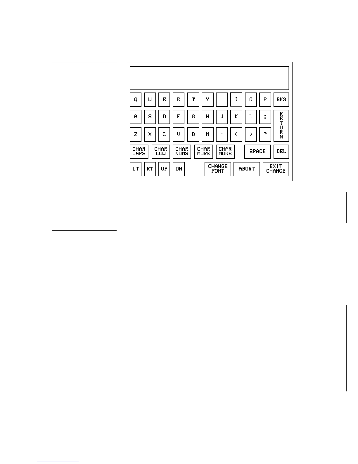
Figure 62
Keyboard
pages.
Panel Design Program.
Note
The CHANGE FONT button
only appears when changing
the font of a function button
and does not apply to popup
6. Enter MAIN PAGE. The text appears in the message box at the top of the key-
board. If you exceed the space in the button, the touch panel edits the message to
fit in the space provided. Change the size of the button or reduce the font size to
compensate.
Note
You can’t create or edit buttons with Unicode fonts within
the on-board editor. Any use
of the TEXT/IMAGE button to
alter or create Unicode font
supported buttons must be
done in TPDesign3 Touch
7. Press EXIT CHANGE to close the keyboard and return to the Text/image page.
8. Press MAKE ON SAME AS OFF to set the text for both TEXT ON and TEXT OFF
states of the button.
9. Press EXIT SAVE CHANGE to close the Text/image page and return to the Main
page.
10. Press EXIT in the Edit bar to exit Edit TEXT/IMAGE mode.
Adding an icon to a button
Use the BUTTON option in the Edit bar to add icons to buttons, joysticks, bargraphs,
and video windows.
1. Press EDIT to open the Edit bar.
2. Press BUTTON on the Edit bar to open the BUTTON menu.
3. Press TEXT/IMAGE to add text to the button. The TEXT/IMAGE operation bar
appears.
4. Press the button to open the Text/image page.
Color Active-Matrix LCD Mini-Touch Panels Designing Touch Panel Pages 43
Page 52

Figure 63
ICONS menu example
5. Press ICON OFF to set the icon for the OFF state of the selected button. This
opens the ICONS menu. The ICONS menu contains a list of all the icons currently available to the project. An example ICONS menu is shown in Figure 63.
6. Select an icon from the icon menu. This sets the icon for the selected button’s Off
state.
7. On the Text/image page, press MAKE ON SAME AS OFF to set the icon for both
On and Off states of the button.
8. Press EXIT SAVE CHANGE to set the button text and close the Text/image page
and return to the NEW page.
9. Press EXIT in the Edit bar to exit Edit Text/Image mode and close the Edit bar.
Adding a bitmap to a button
Use the BUTTON option in the Edit bar to add bitmaps to buttons, joysticks, bargraphs, and video windows.
1. Press EDIT to open the Edit bar.
2. Press BUTTON on the Edit bar to open the BUTTON menu (Figure 44).
3. Press TEXT/IMAGE to add text to the button. The TEXT/IMAGE operation bar
shown in Figure 60 appears.
4. Press the button to open the Text/image page shown in Figure 61.
44 Designing Touch Panel Pages Color Active-Matrix LCD Mini-Touch Panels
Page 53
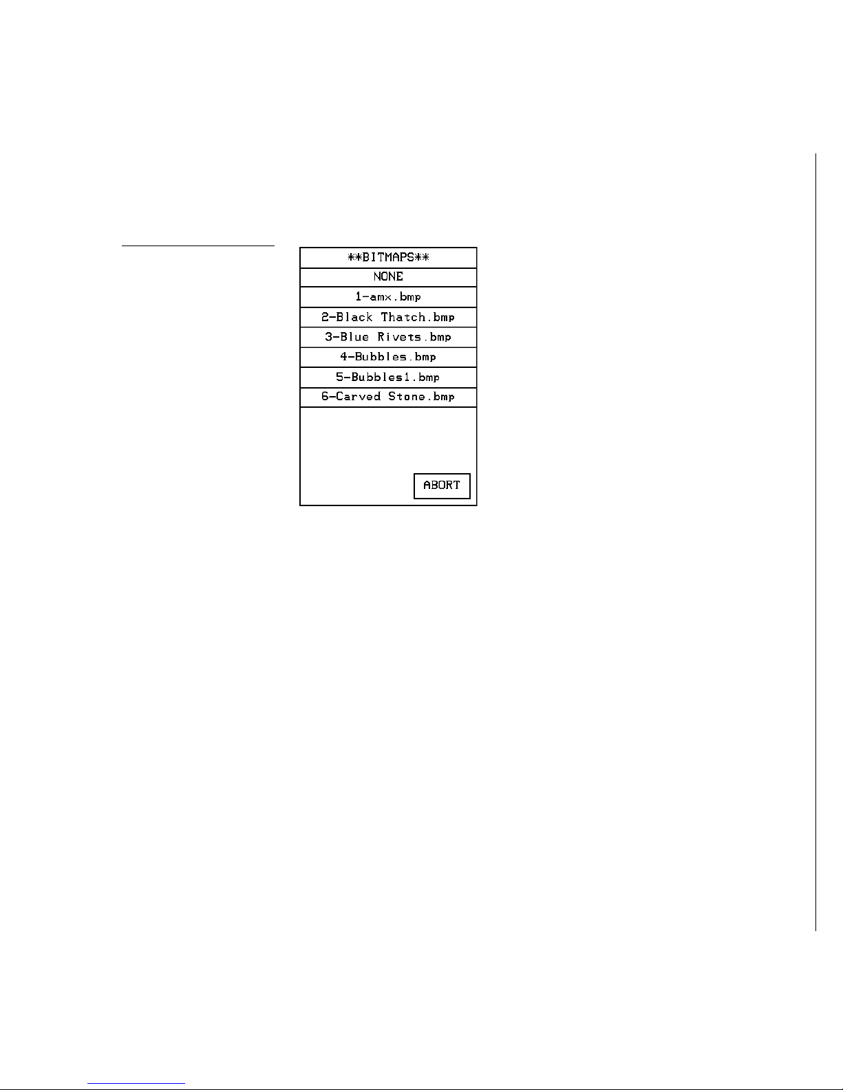
Figure 64
BITMAPS menu example
5. Press BTMP OFF to set the bitmap for the OFF state of the selected button. This
opens the BITMAPS menu. The BITMAPS menu contains a list of all the bitmaps
currently available to the project. An example BITMAPS menu is shown in
Figure 64.
6. Select a bitmap from the bitmap menu. This sets the bitmap for the selected but-
ton’s Off state.
7. On the Text/image page, press MAKE ON SAME AS OFF to set the bitmap for
both On and Off states of the button.
8. Press EXIT SAVE CHANGE to set the button text and close the Text/image page
and return to the NEW page.
9. Press EXIT in the Edit bar to exit Edit Text/Image mode and close the Edit bar.
Using TPDesign3 to Download Bitmaps, Icons and Fonts
The TPDesign3 touch panel design software program allows you to import bitmaps
icons and fonts into your touch panel from an existing touch panel program. Use the
Download to Panel feature of TPDesign3 to download a project file. For detailed instructions on using TPDesign3, refer to the TPDesign3 Touch Panel Program instruction
manual.
The following steps describe how to download bitmaps, icons and/or fonts from an
existing TPDesign3 project file.
1. Launch the TPDesign3 software program and open a project file that contains the
desired bitmaps, icons and fonts.
Color Active-Matrix LCD Mini-Touch Panels Designing Touch Panel Pages 45
Page 54

Figure 65
TPDesign3 File menu
2. Select File from the menu bar to open the File menu, shown in Figure 65.
3. In the File menu, click on Download to Panel. This opens the Download to Panel
dialog boxes shown in Figure 66 and Figure 67. Use the Comm Settings tab
(Figure 66) to set the communications port, baud rate, and other communication
settings.
Figure 66
Download to Panel dialog
box: Comm Settings tab
46 Designing Touch Panel Pages Color Active-Matrix LCD Mini-Touch Panels
Page 55

Figure 67
Sample Download To Panel
dialog box: Actions tab
4. Use the Actions tab (Figure 67) to set the communication mode with the touch
panel and to select which elements of the project file you want to download to
the touch panel.
5. In the What To Send area, select one or more of the available options (Bitmaps,
Icons, Fonts).
6. Select the mode of communication with the touch panel. After clicking on Con-
nect, the AXlink window opens, as shown in Figure 68. The AXlink window displays the AXlink ID and Available Panels fields.
7. The AXlink ID field displays the selected AXlink address. The Available Panels
field the device addresses that are available.
8. Once you have selected which elements to download, and set the communica-
tions mode and AXlink device settings, click Begin to begin downloading the
project file into the touch panel. The bargraph at the bottom of the Download To
Panel dialog box indicates the progress (in percent) of the download.
Color Active-Matrix LCD Mini-Touch Panels Designing Touch Panel Pages 47
Page 56

Figure 68
erties’ page features.
Sample Download To Panel
dialog box with AXlink window
9. After completing the download, cut, copy and paste buttons as needed. The
bitmaps, icons and fonts that were downloaded are now accessible via the
BITMAPS, ICONS and FONTS menus.
Note
Although these pushbuttons
don't appear on-screen, their
functionality can be set just as
any other button on the touch
panel. Refer to the Button
Properties subsection for further information on the Prop-
Figure 69
Joystick
Button Properties for External Pushbuttons
If your touch panel comes with external pushbuttons, these can be configured with
features similar to on-screen buttons. Refer to Creating a Button, Button Properties, and
Properties Page — External Buttons for detailed information. Use the PROPERTIES operation bar to assign properties to external pushbuttons. The BUTTON options and
VARIABLE TEXT features within the Properties page will not appear. Although the
Border and Color sections of this page appear, they are of no use to external pushbuttons since they do not appear on-screen.
Creating a Joystick
You can create a joystick with the BUTTON TYPE operation bar in the Button Properties page. Joysticks (Figure 69) are vertical and horizontal direction controllers (pan
and tilt) you can use for camera operations.
48 Designing Touch Panel Pages Color Active-Matrix LCD Mini-Touch Panels
Page 57
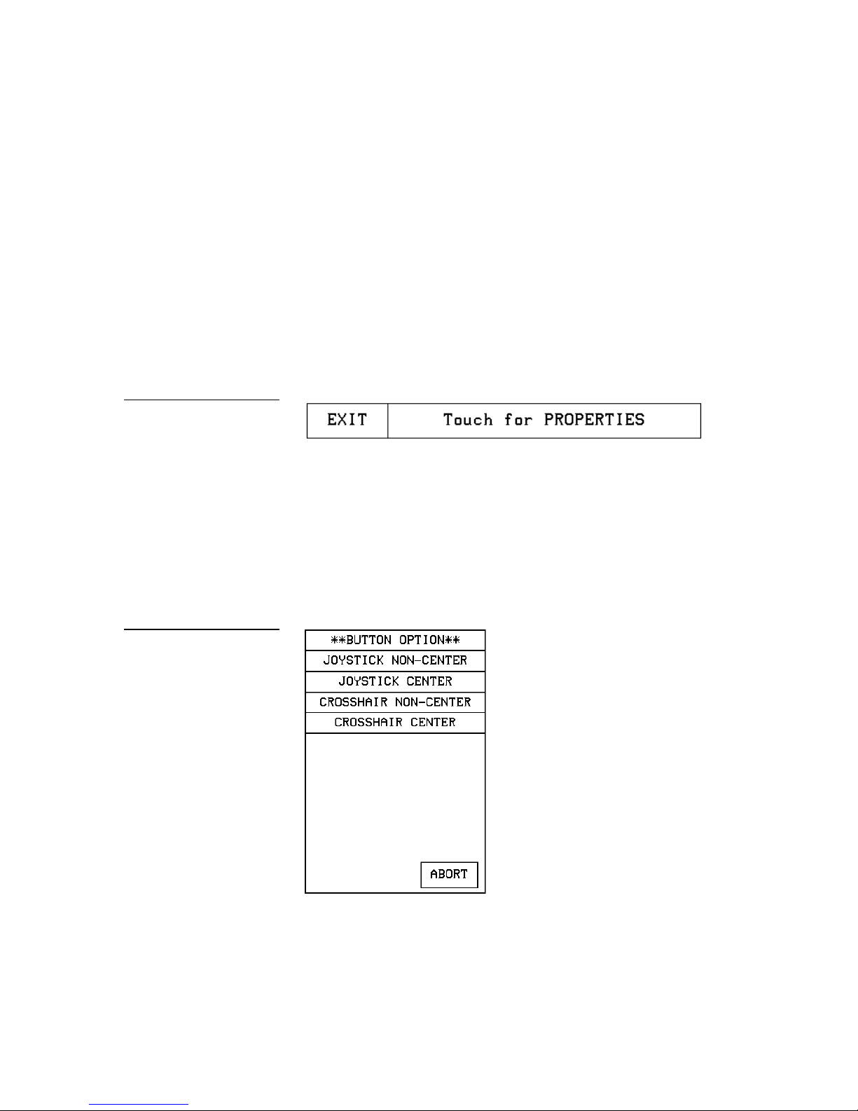
Figure 70
PROPERTIES operation bar
Before you start, make sure to connect the touch panel to your Central Controller.
Otherwise, the joystick may not work properly. Refer to the Touch Panel Program Ref-
erence section in this manual for more information.
Adding a joystick to a page
1. Create a new button using the ADD operation bar in the BUTTON menu as de-
scribed in Creating a Button subsection.
2. Press BUTTON on the Edit bar to open the Button menu.
3. Press PROPERTIES to open the PROPERTIES operation bar shown in Figure 70.
4. Press the target button to open the Button Properties page for the selected button.
5. Press BUTTON TYPE to open the BUTTON TYPE menu.
6. Press JOYSTICK to set the target button as a joystick.
Figure 71
BUTTON OPTION menu for
Joysticks
7. Press BUTTON OPTIONS on the Button Properties page to open the BUTTON
OPTION menu for Joysticks shown in Figure 71.
8. Press CROSSHAIR CENTER to set a crosshair in the center of the joystick button
and return to the Button Properties page.
Color Active-Matrix LCD Mini-Touch Panels Designing Touch Panel Pages 49
Page 58

Figure 72
Joysticks
Properties page appears.
129, 130, and 131.
CHANNEL code buttons
Button Properties page for
Note
If you followed the instructions
for Adding a joystick to a page
subsection, this button's
9. Press EXIT SAVE CHANGE to return to the Main page.
10. Press EXIT to exit from the PROPERTIES operation bar.
Setting the joystick properties
1. Press EDIT, BUTTON, and the PROPERTIES operation bar.
2. Press the target button to open the Button Properties page.
3. Press BUTTON TYPE to open the BUTTON TYPE menu (Figure 77).
4. Press JOYSTICK in the BUTTON TYPE menu to open the Button Properties page
shown in Figure 72.
Note
If DEVICE USED is set to 4
and Base Device Number is
128, the Central Controller
recognizes bus devices 128,
Figure 73
Setting the channel code
The channel buttons that set the device and button channel codes for the touch panels
are shown in Figure 73.
50 Designing Touch Panel Pages Color Active-Matrix LCD Mini-Touch Panels
Page 59

Note
previous value.
255.
LEVEL code buttons
previous value.
to specify the first level.
The panel will not allow you to
enter a device number greater
than the DEVICE USED without first displaying a decision
box. This box asks you to decide whether you accept the
new selection or default to the
Note
The channel code for nonactive buttons is 0 and for
active buttons is 1 through
Figure 74
1. Press DEV to open a keypad and set the joystick’s device number.
2. Enter 1, 2, 3, or 4 in the keypad. The device number specifies the device number
that the selected channel’s feedback displays.
3. Press ENTER to store the device number into memory, close the keypad, and re-
turn to the Button Properties page.
4. Press CHAN to open the keypad and enter a channel value of 1 through 255 in
the keypad. The AXCESS software program uses the channel code number to
identify the button and its’ programmed operations.
5. Press ENTER to store the channel number in memory, close the keypad, and re-
turn to the Button Properties page.
Setting the level code
The level buttons that set the device and number codes for the touch panels are
shown in Figure 74.
Note
The panel will not allow you to
enter a device number greater
than the DEVICE USED without first displaying a decision
box. This box asks you to decide whether you accept the
new selection or default to the
Note
Joysticks actually use two
level numbers. The first is for
the X-axis and the second is
for the Y-axis. You only need
1. Press DEV to open a keypad and set the device number.
2. Enter 1, 2, 3, or 4 in the keypad. The AXCESS software program uses device
codes 1 through 4 to identify the touch panel. Refer to the Touch Panel Program
Reference section for detailed information.
3. Press ENTER to store the level device number in memory, close the keypad, and
return to the Button Properties page.
4. Press NUM to open a keypad and set the level number assigned to the device.
5. Enter 1 in the keypad.
6. Each device can have from 1 through 8 levels except for joysticks where the range
is from 1 through 7.
Color Active-Matrix LCD Mini-Touch Panels Designing Touch Panel Pages 51
Page 60

Figure 75
PROPERTIES operation bar
Bargraph
Creating a Bargraph
Bargraphs (Figure 75) are level monitors and adjustable level controls. These levels
can be configured to monitor audio outputs, lighting levels, and adjust audio or light
levels. Before you start, make sure to connect the touch panel to your Central Controller. Otherwise, the bargraph may not work properly. Refer to the Touch Panel Pro-
gram Reference section for detailed information.
Adding a bargraph to a page
1. Press EDIT to open the Edit bar.
2. Create a new button using the ADD operation bar in the BUTTON menu.
Figure 76
3. Press BUTTON in the Edit bar to open the BUTTON menu.
4. Press PROPERTIES in the BUTTON menu to open the PROPERTIES operation
bar shown in Figure 76.
5. Press the target button to open the Button Properties page.
6. Press BUTTON TYPE to open the BUTTON TYPE menus shown in Figure 77.
52 Designing Touch Panel Pages Color Active-Matrix LCD Mini-Touch Panels
Page 61

Figure 77
BUTTON TYPE menus
Figure 78
Button Properties page for
Vertical Bargraphs
7. Select VERTICAL BARGRAPH to open the Button Properties page for Vertical
Bargraphs shown in Figure 78.
Color Active-Matrix LCD Mini-Touch Panels Designing Touch Panel Pages 53
Setting the bargraph properties
Use the Button Properties page for Vertical Bargraphs shown in Figure 78 to set
channel, level, and button colors.
Page 62

Figure 79
buttons
previous value.
255.
LEVEL code buttons
previous value.
Bargraph CHANNEL code
Note
The panel will not allow you to
enter a device number greater
than the DEVICE USED without first displaying a decision
box. This box asks you to decide whether you accept the
new selection or default to the
Setting the channel code
The channel buttons that set the device and button channel codes for the touch panels
are shown in Figure 79.
1. Press DEV to open the keypad and set the device number.
2. Enter 1, 2, 3, or 4 in the keypad. The AXCESS software program uses device
codes 1 through 4 to identify the touch panel. Refer to the Touch Panel Program
Reference section for detailed information.
3. Press ENTER to store the device number into memory, close the keypad, and re-
turn to the Button Properties page.
Note
The channel code for nonactive buttons is 0 and for
active buttons is 1 through
Figure 80
Note
The panel will not allow you to
enter a device number greater
than the DEVICE USED without first displaying a decision
box. This box asks you to decide whether you accept the
new selection or default to the
4. Press CHAN to open a keypad and enter a channel value of 1 through 255 in the
keypad. The AXCESS software program uses the channel code number to identify the button and its’ operations.
5. Press ENTER to store the channel number into memory, close the keypad, and
return to the Button Properties page.
Setting the level code
The level buttons that set the device and number codes for the touch panels are
shown in Figure 80.
1. Press DEV to open a keypad and set the device number.
2. Enter 1, 2, 3, or 4 in the keypad. The AXCESS software program uses device
codes 1 through 4 to identify the touch panel. Refer to the Touch Panel Program
Reference in this manual for detailed information.
3. Press ENTER to store the level device number into memory, close the keypad,
and return to the Button Properties page.
54 Designing Touch Panel Pages Color Active-Matrix LCD Mini-Touch Panels
Page 63

Figure 81
ton
TEXT/IMAGE operation bar
that resides in the Main page.
Active page button
Edit bar with active page but-
4. Press NUM to open a keypad and set the level number assigned to the device.
5. Enter 1 in the keypad.
6. Press ENTER to store the level number into memory, close the keypad, and re-
turn to the Button Properties page.
7. Press EXIT SAVE CHANGE, then EXIT to return to the New page with the EDIT
button.
Linking the New Page to the Main Page
Use the Attributes page to link buttons to pages. This operation requires changing the
button text and setting a page flip. Refer to Adding a page, Creating a Button, Go to, and
Setting the page flip for detailed information.
1. Open the Edit bar, press the active page button shown in Figure 81. Refer to the
Go to subsection for information on the use of the active page button.
Figure 82
Note
This refers to the MAIN button
2. Press MAIN PAGE from the PAGE GOTO menu (Figure 192).
3. Press EDIT to open the Edit bar.
4. Press BUTTON on the Edit bar to open the BUTTON menu.
5. Press TEXT/IMAGE to change the Main page button text. The TEXT/IMAGE
operation bar (Figure 82) appears.
6. Press the MAIN button to open the Text/image page.
7. Press TEXT OFF to open the keyboard and delete MAIN.
8. Enter NEW PAGE. The text appears in the keyboard window as shown in
Figure 83.
Color Active-Matrix LCD Mini-Touch Panels Designing Touch Panel Pages 55
Page 64

Figure 83
Keyboard: NEW PAGE
9. Press EXIT CHANGE to close the keyboard and return to the Text/image page.
10. Press MAKE ON SAME AS OFF to set the text for the button’s TEXT ON and
TEXT OFF states.
11. Press EXIT SAVE CHANGE to close the Text/image page and return to the Main
page.
Figure 84
PROPERTIES operation bar
12. Press EXIT to exit the TEXT/IMAGE mode.
13. Press EDIT to open the Edit bar.
14. Press BUTTON to open the BUTTON OPTIONS menu.
15. Press PROPERTIES in the BUTTON OPTIONS menu to open the PROPERTIES
operation bar shown in Figure 84.
16. Press the NEW PAGE button to open the Button Properties page.
17. Press the page FLIP buttons (Figure 85) to set the page flip properties for the but-
ton.
56 Designing Touch Panel Pages Color Active-Matrix LCD Mini-Touch Panels
Page 65
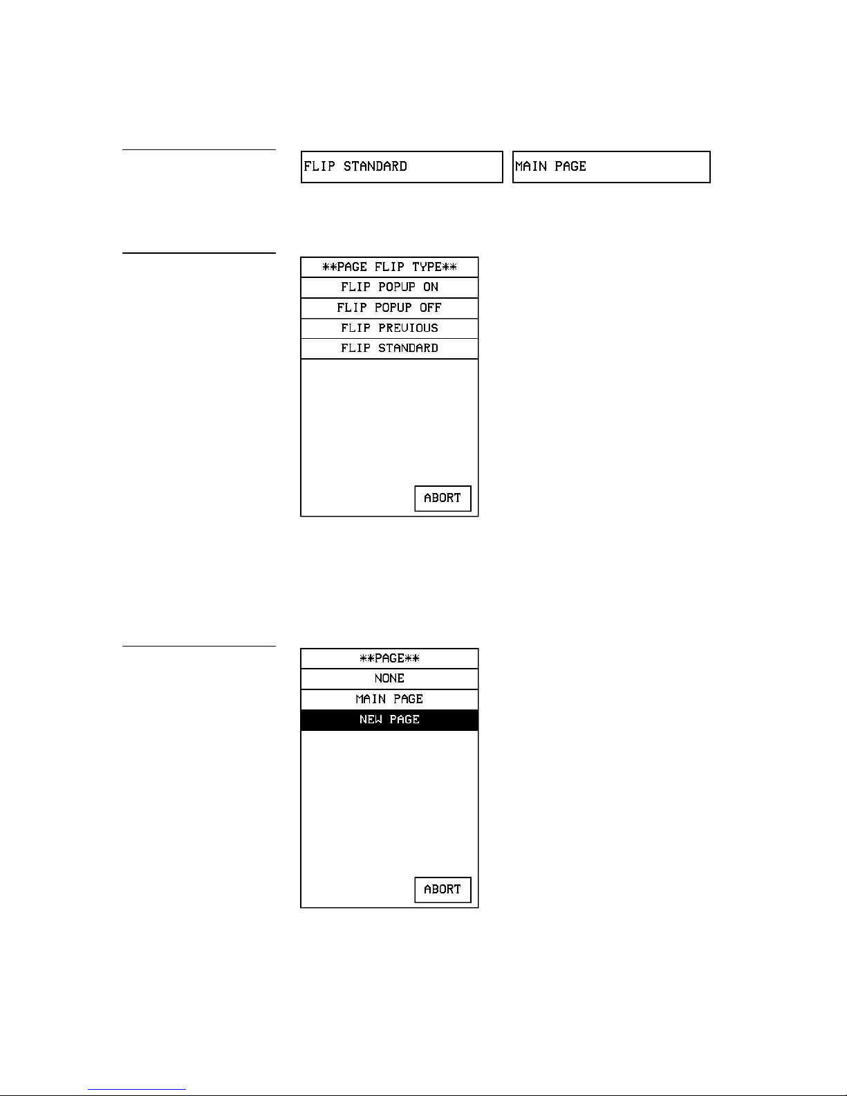
Figure 85
Page FLIP buttons
Figure 86
PAGE FLIP TYPE menu
18. Press the left page FLIP box to open the PAGE FLIP TYPE menu (Figure 86).
19. Press FLIP STANDARD to set the page flip type and return to the Button Proper-
ties page.
Figure 87
PAGE menu
20. Press the right Flip to page button to set the destination page (Figure 87).
Color Active-Matrix LCD Mini-Touch Panels Designing Touch Panel Pages 57
Page 66

Figure 88
Edit bar
Figure 89
Setup page
21. Press NEW PAGE to set the page flip and return to the Button Properties page.
22. Press EXIT SAVE CHANGE to save changes, close the Button Properties page,
and return to the Main page.
23. Press EXIT on the PROPERTIES operation bar to close the Edit bar.
Exiting Edit Mode
This subsection describes how to exit the EDIT mode once you finish designing
touch panel pages.
1. Press EXIT to close the Edit bar (Figure 88).
2. Press SETUP to open the Setup page shown in Figure 89.
3. Press PROTECTED SETUP to open the Protected Setup page shown in
Figure 90.
58 Designing Touch Panel Pages Color Active-Matrix LCD Mini-Touch Panels
Page 67

Figure 90
Protected Setup page
4. Press EDITOR to toggle EDIT mode off.
5. Press EXIT to close the Protected Setup page and return to the Setup page
(Figure 89).
6. Press EXIT to close the Setup page and return to the Main page.
Another method of exiting the EDIT mode is to use the QUIT EDITOR button on the
Edit bar. Refer to the Edit Bar — Quit Editor option subsection for detailed information
on exiting the EDIT mode using this method.
To exit the EDIT mode using the QUIT EDITOR button:
1. Press EXIT to open the Edit bar shown in Figure 88.
2. Press the QUIT EDITOR button to open the Quit the On-Board Editor decision
button.
3. If you select YES, the current page will appear without the Edit bar.
Color Active-Matrix LCD Mini-Touch Panels Designing Touch Panel Pages 59
Page 68

60 Designing Touch Panel Pages Color Active-Matrix LCD Mini-Touch Panels
Page 69
SETUP
Figure 91
Main page
Setup page flowchart
Touch Panel Program Reference
Overview
Use the Setup and Protected Setup pages to configure how the touch panel operates.
This section contains operation flowcharts, instructions, and menu option descriptions. The buttons shown in Figure 91 appear when you power up the touch panel.
Figure 92
Setup Page
The flowchart in Figure 92 shows the buttons you press to access the Setup page.
MAIN
PAGE
From the Main page, press the SETUP button to open the Setup page shown in
Figure 93.
Color Active-Matrix LCD Mini-Touch Panels Touch Panel Program Reference 61
Page 70

Figure 93
Setup page
the touch panel.
BEEP button
overriding.
control systems.
Note
The WIRELESS STATUS
button appears when a WAVPK or SMT-PK is attached to
Optional
WIRELESS
STATUS button for
WAV-PKM and
SMT-PKM wireless
Beep
The BEEP button (Figure 94) sets the audible beep duration when you touch the
screen.
Figure 94
Note
You can set the beep value
setting using the
'ADBEEP' Send_ Commands
described in the AXCESS
Programming section. The
'QBEEP' command is used for
'ABEEP' and
Set the BEEP button to 0 to disable the beep sound. Press the UP and DN buttons to
set beep time in .10-second increments. The minimum beep time setting is 0 and the
maximum is 5 (0.5-second duration).
Display timer
The DISPLAY TIMER button (Figure 95) sets the length of time the touch panel can
be idle before activating screen-saver mode.
62 Touch Panel Program Reference Color Active-Matrix LCD Mini-Touch Panels
Page 71
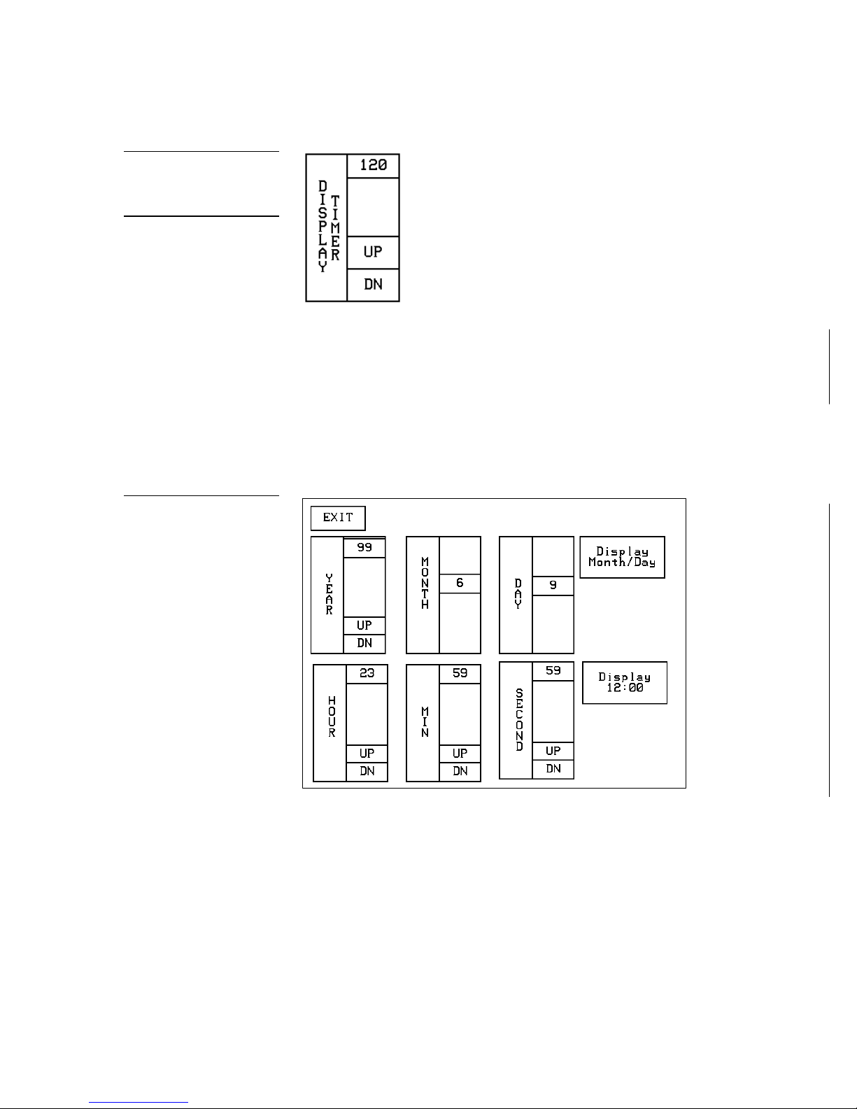
Figure 95
DISPLAY TIMER button
out and will always remain on.
Note
The DISPLAY TIMER button
can now be set to zero. In this
case, the panel will never time
Figure 96
Set Time And Date page
When the touch panel goes into screen-saver mode, the LCD is powered-down. With
a setting of 5, the panel goes into screen-saver mode if there is no activity for 5 minutes. Press the UP and DN buttons to set the DISPLAY TIMER. The minimum time is
1 minute and as long as there is power, with a setting of 0 there is no maximum.
Set time and date
Press SET TIME AND DATE to open the page shown in Figure 96.
Color Active-Matrix LCD Mini-Touch Panels Touch Panel Program Reference 63
Set the year, hour, month, minute, day, second, day/month, and clock display.
YEAR Press the UP and DN buttons to set the year.
•
HOUR Press the UP and DN buttons to set the hour.
•
MONTH Press the UP and DN buttons to set the month.
•
MIN Press the UP and DN buttons to set the minute.
•
Page 72

Figure 97
DOUBLE BEEP button
overriding.
ples
• DAY Press the UP and DN buttons to set the day.
SECOND Press the UP and DN buttons to set the seconds.
•
DISPLAY MONTH/DAY, DAY/MONTH Press to set the order of the month
•
and day display.
DISPLAY 12:00/24:00 Press to set the clock display to a 12- or 24-hour
•
format. For example, the 12-hour clock format changes from 12:00 to 1:00,
and the 24-hour clock changes from 12:00 to 13:00.
Double beep
Press the DOUBLE BEEP button (Figure 97) to toggle the double beep ON or OFF.
The double beep sounds each time you press the screen.
Note
You can set the beep value
setting using the
'ADBEEP' Send_ Commands
described in the AXCESS
Programming section. The
'QBEEP' command is used for
Figure 98
AXlink, OUT RES, vX.XX,
and SERIAL # button exam-
'ABEEP' and
Set the BEEP button (described earlier) to 0 to disable the double-beep sound.
AXlink, output resolution, vX.XX, and serial number
The AXlink, OUTPUT RESOLUTION, vX.XX, and SERIAL # buttons shown in
Figure 98 are information buttons (display only).
The AXlink button is an AXCESS communication indicator that blinks once every
second when the Central Controller is connected to the touch panel. The OUTPUT
RESOLUTION button shows the screen resolution. The vX.XX button shows the current firmware version installed in the touch panel. The SERIAL # button shows the
serial number for the touch panel.
Set brightness
Press SET BRIGHTNESS in the SETUP page to open the page shown in Figure 99.
64 Touch Panel Program Reference Color Active-Matrix LCD Mini-Touch Panels
Page 73
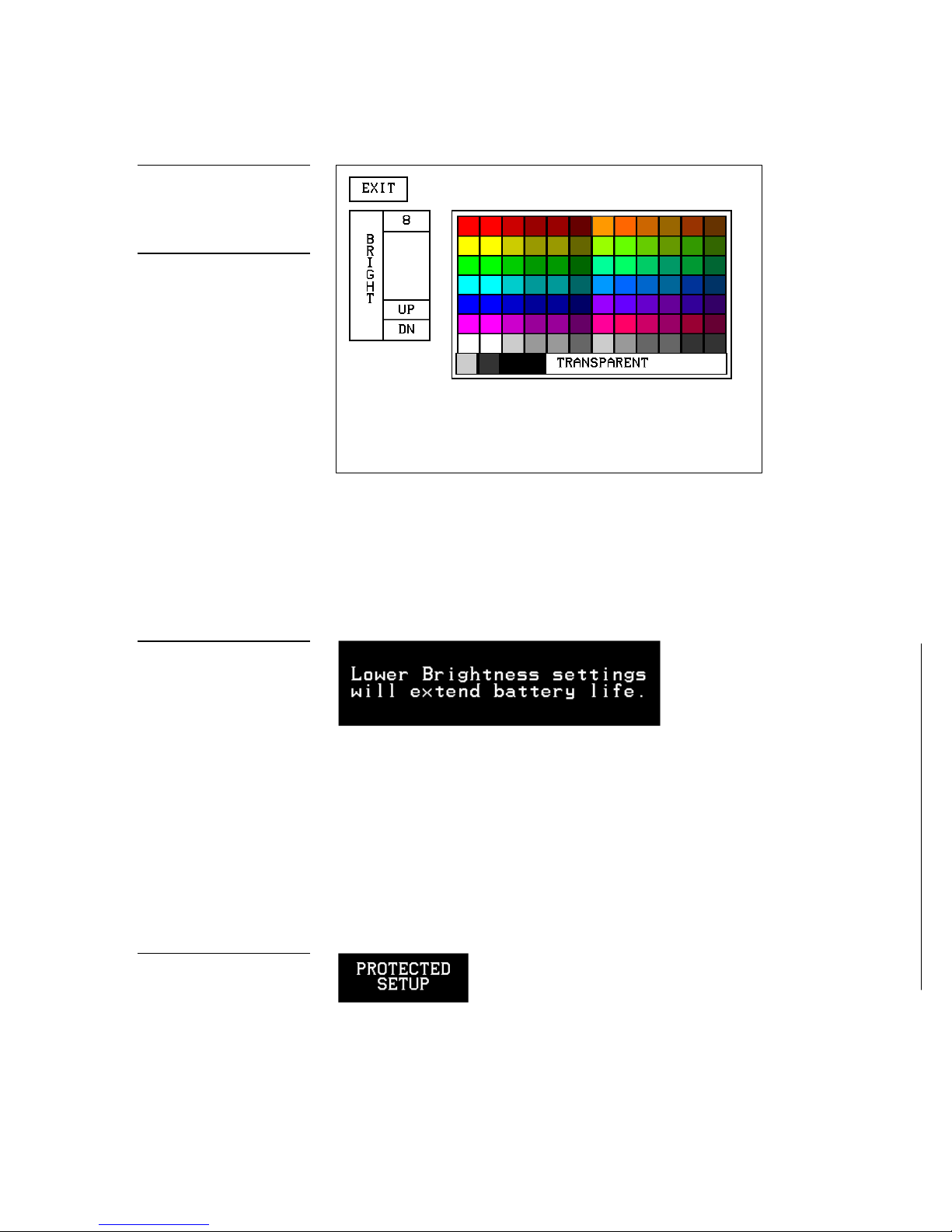
Figure 99
setting exceeds 5.
(highlighted)
Set Brightness page
Note
When the panel is attached to
an optional battery source, a
lower brightness settings information button appears in
the lower right-hand of the
screen when the brightness
Press the UP and DN buttons to set the LCD brightness and contrast on the touch
panel. The maximum brightness level is 8. The TRANSPARENT and ABORT buttons
are disabled on this page. When an optional WavePack/SmartPack is attached to a
panel, a lower brightness message (Figure 100) will appear to suggest brightness settings for longer battery life.
Figure 100
Lower brightness information
message
Figure 101
PROTECTED SETUP button
Protected setup
The PROTECTED SETUP button opens the Protected Setup page where you set touch
panel passwords, mouse control, communications parameters, etc. The PROTECTED
SETUP button is highlighted when enabled, as shown in Figure 101. Because there are
many operations associated with Protected Setup page, they are described in the Pro-
tected Setup Page subsection.
Color Active-Matrix LCD Mini-Touch Panels Touch Panel Program Reference 65
Page 74

Show palette
TIMEOUT for the touch panel.
WAV-PKM page
the mini touch panels.
back of the Mini-WavePack.
Press SHOW PALETTE to open the color palette. Pressing the screen again will cause
you to leave the Show Palette page.
Note
The WAV-PKM page provides
information about the WavePack. The only setting which
can be changed is the SLEEP
Figure 102
Note
The mini touch panels require
different types of battery
packs than the 8.5” and 10.4”
touch panels. The WAV-PKM
and SMT-PKM are made for
Wireless status (optional WAV-PKM)
The WIRELESS STATUS button appears on the Setup page when an AXR-WAVES
Wireless AXlink Virtual Emulator Server is connected to the touch panel. The WAVPKM provides wireless two-way RF spread-spectrum touch panel control and contains a lead-acid rechargeable battery that supplies independent power to the panel.
Refer to the WAVE 2-Way Wireless Accessories and Adapters for Touch Panels instruction
manual for detailed setup information. Press the WIRELESS STATUS button to open
the WAV-PKM page shown in Figure 102.
The Mini-Wave-Pack page shows the following information:
Note
All mini-touch panels wake by
pushing the button on the
SLEEP TIMEOUT Press the UP and DN buttons to set the sleep time-out.
•
The minimum time-out is 1 minute and maximum is 120 minutes. When the
touch panel goes to sleep, all communication and battery discharge stops. If
the time-out is set to 5, the panel goes into sleep mode if there is no activity
for 5 minutes. The touch panel automatically wakes up when you touch the
screen for more than .5 seconds.
Wave-Pak Not Locked/Locked Appears when an optional WAV-PKM
•
is connected to the touch panel. Not locked indicates the touch panel is not
communicating with the AXR-WAVES. Locked indicates the touch panel is
66 Touch Panel Program Reference Color Active-Matrix LCD Mini-Touch Panels
Page 75

Note
for detailed information.
The GROUP ID number can
be set from the Wireless Settings page in the Protected
Setup page. Refer to the
Wireless settings subsection
Note
Both Network Eff. XXX% and
Device Eff. XXX% are the
best indicators of communication.
locked on (communicating) to the AXR-WAVES connected to the Central
Controller.
Battery Voltage XX.X Shows the voltage level of the lead-acid recharge-
•
able battery in the WAV-PKM.
• RSSI XXX% Shows the strength of the AXR-WAVES signal received by
the touch panel. The signal strength fluctuates between 0% and 100% as
shown by a horizontal gauge moving from left to right.
GROUP ID Shows the GROUP ID number on the touch panel used to
•
communicate with the wireless AXR-WAVES with the same group ID number. The group ID range is 0 – 15. The group ID setting overrides the DIP
switch setting on the WAV-PKM.
Module Version vX.XX Shows the firmware version installed in the
•
WAV-PKM.
• Fully Charged/Not Charging/Charging Fully Charged appears when
the battery in the WAV-PKM is fully charged. Not Charging appears when
the lead-acid battery is not charging. Charging appears when the lead-acid
battery is charging. The shaded area is a horizontal gauge moving from left
to right as the battery voltage level increases.
Network Eff. XXX% Shows the communication efficiency of bidirectional
•
RF transmissions between the touch panel and AXR-WAVES. The efficiency
percentage (0–100%) is determined by the number of retries required to
complete a panel operation.
Device Range Shows the device range that your server can recognize.
•
Devices outside that range will not be recognized.
Color Active-Matrix LCD Mini-Touch Panels Touch Panel Program Reference 67
Server Devices XXX Shows the group address for the AXR-WAVES
•
communicating with the touch panel.
Server Version Shows the firmware version installed in the AXR-
•
WAVES.
Supply Voltage vX.XX Shows the voltage level of the external power
•
supply (optional) connected to the WAV-PKM.
Device Eff. XXX% Shows the strength of the AXR-WAVES signal re-
•
ceived by the touch panel. The shaded area in the horizontal gauge moves
from left to right as the RF signal intensity increases. The shaded area fluctuates between 0% and 100%.
Page 76

Note
TIMEOUT for the touch panel.
SMT-PKM page
set the RF and IR.
This SMT-PKM page provides
information about the SmartPack. The only setting which
can be changed is the SLEEP
Figure 103
Wireless status (optional SMT-PKM)
The WIRELESS STATUS button appears on the Setup page when a SmartPack is connected to the touch panel. Press the WIRELESS STATUS button to open the optional
page shown in Figure 103.
Note
Refer to the Wireless status
(optional WAV-PKM) subsec-
tion for information on how to
Refer to the SmartPacks for TiltScreen Touch Panels instruction manual for detailed information. The Mini-SmartPack page shows the following information:
SLEEP TIMEOUT Press the UP and DN buttons to set the time-out. The
•
minimum time-out is 1 minute and maximum is 120 minutes. When the
panel goes to sleep, all communication and battery discharge stops. If the
time-out is set to 5, the panel goes into sleep mode if there is no activity for 5
minutes. The panel wakes up when you touch the screen.
Smart-Pak Not Locked/Locked Appears when an optional SMT-PKM
•
is connected to the panel. Not locked indicates the panel is not communicating with the AXR-RF RF receiver. Locked indicates the panel is locked on to
the AXR-RF connected to the Central Controller.
Battery Voltage XX.X Shows the voltage level of the lead-acid recharge-
•
able battery in the SMT-PKM.
Module Version vX.XX Shows the firmware version installed in the
•
SMT-PKM.
Fully Charged/Not Charging/Charging Fully Charged appears when
•
the battery in the SMT-PKM is fully charged. Not Charging appears when
68 Touch Panel Program Reference Color Active-Matrix LCD Mini-Touch Panels
Page 77

the lead-acid battery is not charging. Charging appears when the lead-acid
BUTTON
chart
Protected Setup page.
battery is charging. The shaded area is a horizontal gauge moving from left
to right as the battery voltage level increases.
AMX RF ON/OFF Shows RF transmission on or off.
•
Supply Voltage vX.XX Shows the voltage level of the external power
•
supply (optional) connected to the SMT-PKM.
IR 38 kHz/455 kHz/OFF Shows the IR transmitting frequency to 38
•
kHz, 455 kHz, or OFF.
Protected Setup Page
The Protected Setup page allows you to set passwords, mouse control, and communications parameters. The flowchart in Figure 104 shows how to access the Protected
Setup page, which is password-protected. When you press the PROTECTED SETUP
button on the Setup page, a number keypad appears.
Figure 104
Protected Setup page flow-
Note
When the Edit bar is enabled,
you do not have to enter the
password when opening the
MAIN
PAGE
SETUP
BUTTON
PROTECTED SETUP
TYPE
1988
Enter 1988, which is the system default password, and press ENTER to open the Protected Setup page. (You can change the password, as explained in the Setup password
subsection.) If you enter a wrong number, press CLEAR and re-enter the number.
The Protected Setup page (Figure 105) appears when you enter the correct number.
Color Active-Matrix LCD Mini-Touch Panels Touch Panel Program Reference 69
Page 78

Figure 105
Protected Setup page
BAUD button
ternal RS-232 device.
Baud
The BAUD button (Figure 106) sets the baud rate for the DB-9 connector at the rear of
the touch panel. The baud rate is automatically set to 1,200 when you activate the
MOUSE button. The RS-232 communication automatically defaults to Figure 106 if
you disable the MOUSE ON button.
Figure 106
Note
Make sure to match the baud
transmission rate for the ex-
• BAUD Press the UP and DN buttons to set the data communication speed
for the touch panel’s RS-232 (DB-9) port. Available baud rates are 300, 600,
1200, 2400, 4800, 9600, 19.2 KB, and 38.4 KB.
Device base
Press the DEVICE BASE button (Figure 107) to open a keypad and set the base address for the touch panel. The base address range is from1 through 255.
70 Touch Panel Program Reference Color Active-Matrix LCD Mini-Touch Panels
Page 79

Figure 107
DEVICE BASE button
and 131 consecutively.
DEVICE USED button
SETUP PASSWORD button
vide you with the password.
mouse control is active.
MOUSE button
Note
If four devices are used, and
the base address is 128, then
the touch panel will use device numbers 128, 129, 130,
Figure 108
Figure 109
Device used
Press the DEVICE USED button (Figure 108) to open a keypad and set the panel’s device number from 1 through 4. Each device number supports up to 255-channel code
button assignments. The multiple device settings allow you to create up to four
unique touch panel buttons and/or pages. This value is used to determine the current
device being used by the panel.
Setup password
Press the SETUP PASSWORD button (Figure 109) to open a keypad and set the numeric SETUP password.
Warning
The password number range is 1 through 5,999. (Do not use zero.) Do not change the
Setup page password unless you are concerned about unauthorized access to the
If you change the password
number, record the new number and keep it in a secure
place. If you change the
password, AMX cannot pro-
touch panel pages.
CLEAR Press to clear the number in the keypad display.
•
ENTER Press to enter the new password into touch panel memory and
•
close the keypad.
Note
You can still control the touch
panel with your finger when
Figure 110
Color Active-Matrix LCD Mini-Touch Panels Touch Panel Program Reference 71
Mouse button
Press the MOUSE button (Figure 110) to open the Mouse Setup page shown in
Figure 111.
Page 80

Figure 111
Mouse Setup page
• MOUSE SPEED Press the UP and DN buttons to set the mouse pointer
speed. The minimum (slowest) speed is 1 and the maximum (fastest) is 10.
MOUSE ACTIVE Press to activate the mouse pointer. The active mouse
•
pointer appears in the top-left corner of the LCD. When the MOUSE ACTIVE
button is active (Figure 112), this button below it will display the type of
mouse that is attached to the touch panel
Figure 112
MOUSE ACTIVE button
NO MOUSE Indicates that there is no mouse selected for the touch panel.
•
Mouse Active
button
72 Touch Panel Program Reference Color Active-Matrix LCD Mini-Touch Panels
Page 81

Figure 113
and example PAGE menu
WAKE UP MESSAGE button
POWER UP PAGE button
Power up page
Press the POWER UP PAGE button to open the PAGE menu (Figure 113).
Select a page to designate as the first page to appear when you power up the touch
panel. Select NONE to disable this option. If none is selected, the last selected page
will be the first active page the next time the touch panel is used.
Figure 114
Wake up message
Press WAKE UP MESSAGE (Figure 114) to open the touch panel keyboard, and enter
an ASCII string to be sent to the Central Controller when the touch panel wakes up.
You can program the Central Controller to perform specific operations when the
message is received. Refer to the AXCESS Programming section for detailed programming information.
Auto assign
Press AUTO ASSIGN (Figure 115) to enable the automatic channel assignment. This
option sets the touch panel to prompt you to manually or automatically assign a
channel number (1 through 255) to a new button. Once selected, the touch panel assigns the lowest unused channel number to the button. Press the AUTO ASSIGN
again to disable.
Color Active-Matrix LCD Mini-Touch Panels Touch Panel Program Reference 73
Page 82
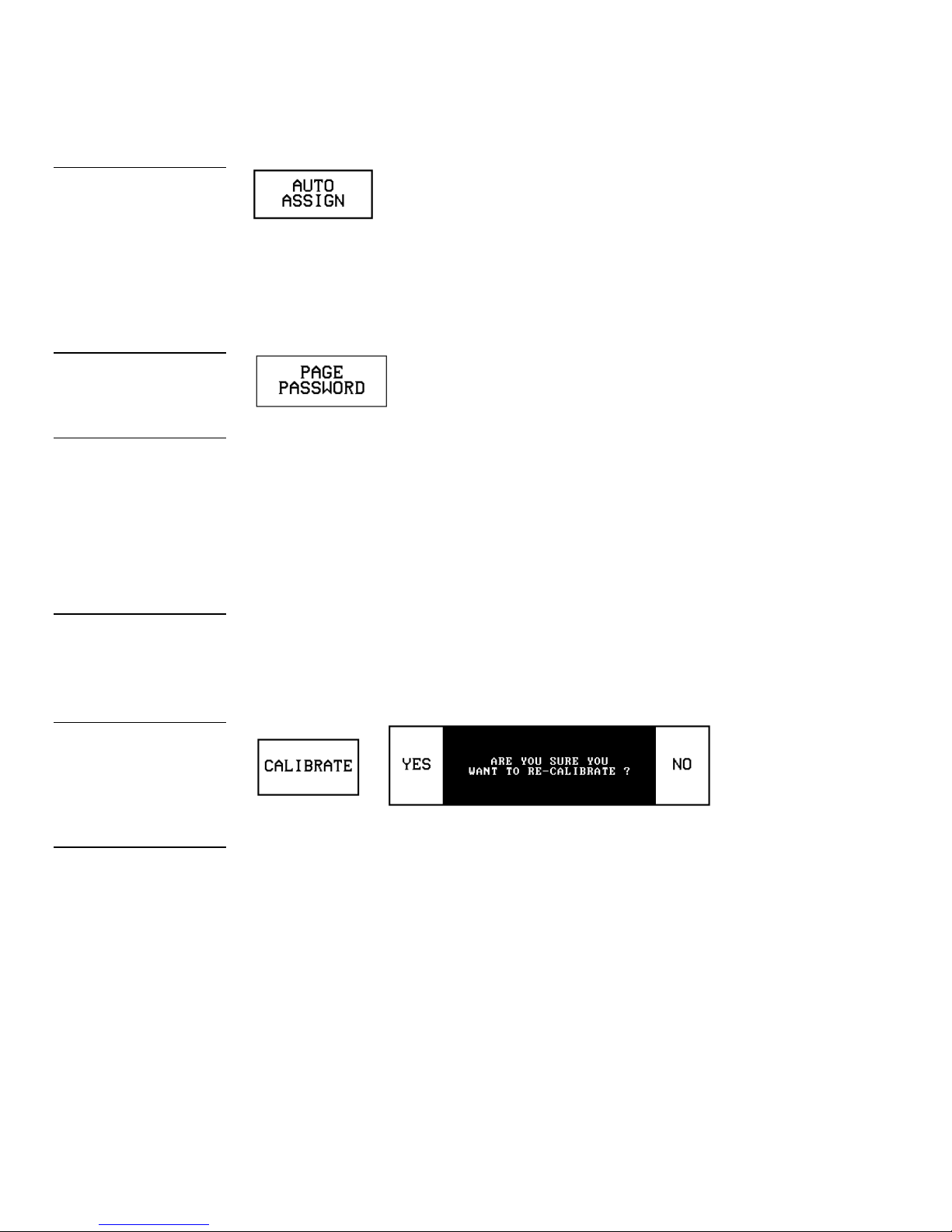
Figure 115
AUTO ASSIGN button
PAGE PASSWORD button
Protected Setup page.
mode.
screen.
Figure 116
Page password
Press the PAGE PASSWORD button (Figure 116) to open a keypad and assign a
page’s numeric password.
Note
This numeric password applies to the touch panel pages
only, and is separate from the
SETUP PASSWORD button
that sets up the numeric
password for access to the
Note
Press and hold for 2 seconds
to enter Calibration Test
Figure 117
CALIBRATE decision button
Note
The crosshair for calibration
is first shown at the top-left
corner of the touch panel
If you try to open a password-protected page, the keypad appears, and you must
enter the correct password number to open the new page. The page password
range is 1–5,999.
CLEAR Clears the number in the keypad display.
•
ENTER Sets the page password number, closes the keypad, and returns
•
to the Protected Setup page.
Calibrate
Press CALIBRATE to open the CALIBRATE decision button shown in Figure 117
and reset the vertical and horizontal touch points on the LCD.
• YES Starts the calibration process. Carefully press each crosshair that
appears using your finger or dull pointer. When the calibration process is
complete, press the screen to return to the Protected Setup page.
NO Cancels the calibration process.
•
Power up message
Press POWER UP MESSAGE (Figure 118) to open the keyboard, and enter an ASCII
string to be sent to the Central Controller when the touch panel is powered up. The
Central Controller can be programmed to perform specific operations when the
74 Touch Panel Program Reference Color Active-Matrix LCD Mini-Touch Panels
Page 83
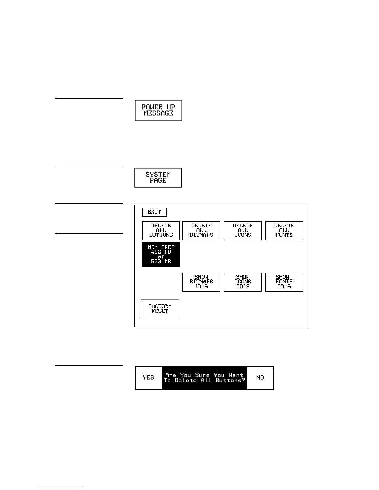
Figure 118
SYSTEM PAGE button
System page
from panel memory.
button
POWER UP MESSAGE button
Figure 119
Figure 120
Warning
The System page should only
be used to purge unwanted
buttons, bitmaps, icons, fonts,
and stored touch panel settings. Before using this page,
make sure you have a backup
copy of the touch panel program stored in the TPDesign3
software program. If you
press YES on any of the
DELETE buttons, the stored
data is permanently erased
sage is received. Refer to the AXCESS Programming section for detailed programming
information.
System page
Press the SYSTEM PAGE button (Figure 119) to open the System page (Figure 120).
• DELETE ALL BUTTONS Opens the decision button shown in Figure 121.
Press YES to clear all touch panel buttons or NO to cancel the operation.
Figure 121
Delete All Buttons decision
Color Active-Matrix LCD Mini-Touch Panels Touch Panel Program Reference 75
• MEM FREE Shows the memory available to store buttons in 1,024-byte in-
crements.
Page 84

Figure 122
button
ton
button
Delete All Bitmaps decision
Figure 123
Delete All Icons decision but-
Figure 124
Delete All Fonts decision
• DELETE ALL BITMAPS Opens the decision button shown in Figure 122.
Press YES to clear all the bitmaps or NO to cancel the operation.
• DELETE ALL ICONS Opens the decision button shown in Figure 123.
Press YES to clear all the icons or NO to cancel the operation.
• DELETE ALL FONTS Opens the decision button shown in Figure 124.
Press YES to clear all the fonts or NO to cancel the operation.
Figure 125
BITMAPS menu
• SHOW BITMAPS ID’S Opens the BITMAPS menu (Figure 125) that lists
bitmap files stored in touch panel memory.
76 Touch Panel Program Reference Color Active-Matrix LCD Mini-Touch Panels
Page 85
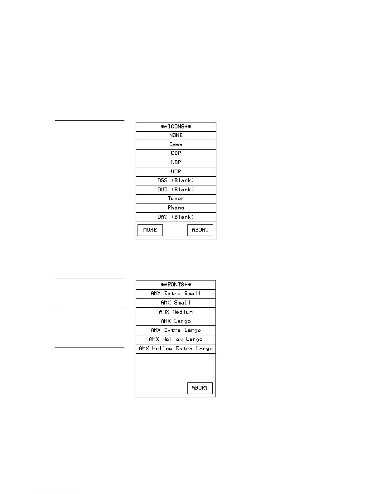
Figure 126
FONTS menu
variable fonts into the panel.
erased.
ICONS menu
• SHOW ICONS ID’S Opens the ICONS menu (Figure 126) that lists icons
stored in touch panel memory.
MORE Forwards the menu listing.
ABORT Cancels the menu process and returns to the current page.
Figure 127
Note
You can use the TPDesign3
software program to import
Warning
You should only use the
FACTORY RESET button to
erase all stored data in the
touch panel. The data cannot
be recovered after it is
• SHOW FONTS ID’S Opens the FONTS menu (Figure 127 lists fonts
stored in touch panel memory.
• FACTORY RESET Opens the decision button shown in Figure 128. Press
YES to clear all touch panel memory or NO to cancel the operation.
Color Active-Matrix LCD Mini-Touch Panels Touch Panel Program Reference 77
Page 86

Figure 128
EDITOR button
tion for detailed information.
EDIT button
Edit bar
PAGE TRACKING button
CLEAR MEMORY decision
button
Figure 129
Editor
Press EDITOR (Figure 129) in the Protected Setup page to activate the EDIT mode.
Note
You can exit from the onboard editor by pressing the
QUIT EDITOR button on the
Edit bar. Refer to the Edit Bar
— Quit Editor option subsec-
Figure 130
Figure 131
When you exit the Protected Setup page, the EDIT button (Figure 130) appears on
the top or bottom of the LCD. You can press the EDIT button to open the Edit bar
(Figure 131) and create buttons, pages, popup pages, and set a wide variety of touch
panel settings. The active touch panel page name also appears in the active Edit
bar. For example, the Edit bar sample in Figure 131 shows the current page name is
Main page. Because there are so many operations associated with the EDIT button,
they are described in the Edit button subsection.
Page tracking
Press PAGE TRACKING (Figure 132) to toggle the page tracking ON or OFF. When
page tracking is enabled, the touch panel sends page data back to the Central Controller or vice versa depending on how you set the touch panel. Page tracking data
can be used to control pages in multiple touch panels.
Figure 132
78 Touch Panel Program Reference Color Active-Matrix LCD Mini-Touch Panels
Page 87
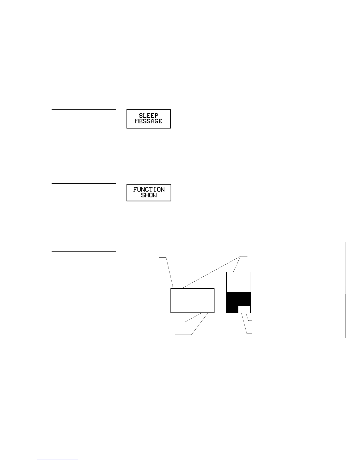
PANEL
3, 132
1,255
Button
Slider
number
device number
2, 255
2, 1
number
Text channel
Level channel
number
Figure 133
SLEEP MESSAGE button
FUNCTION SHOW button
Figure 134
Sleep message
Press SLEEP MESSAGE (Figure 133) to open a keyboard and enter a message to appear when the touch panel goes into sleep mode. Refer to Display Timer to set the
touch panel’s screen-saver mode.
Function show
Press FUNCTION SHOW (Figure 134) to display channel code numbers and variable
text code numbers on touch panel buttons, joysticks, sliders, and bargraphs.
As shown in Figure 135, the upper-left corner of a button shows a base device number followed by a channel code number. The bottom-right corner of a button shows
the variable text number followed by the variable text channel.
Figure 135
Function show button and
slider example
Base device
Variable text
Channel code
LIGHT
Level device
Color Active-Matrix LCD Mini-Touch Panels Touch Panel Program Reference 79
Page 88
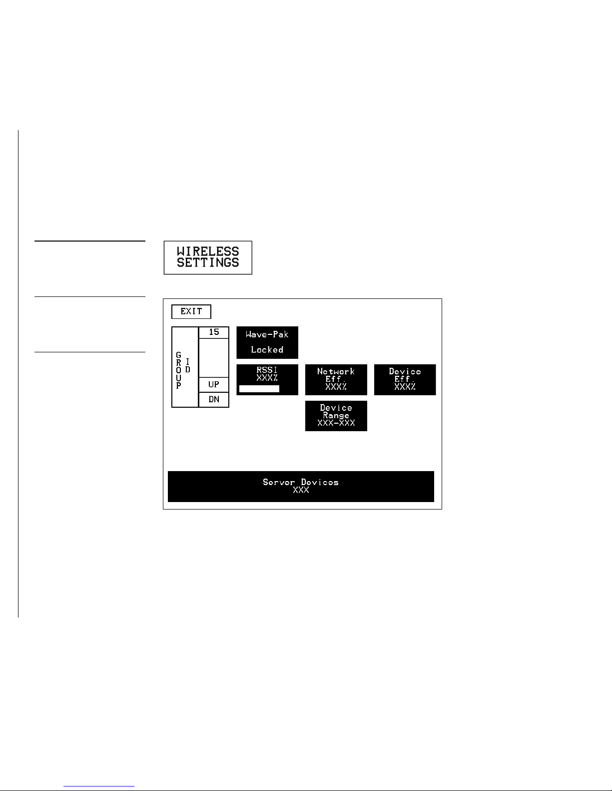
Figure 136
ton
detailed information.
WIRELESS SETTINGS but-
Figure 137
Wireless Settings page
Note
The GROUP ID can be altered. Once changed, the
value is reflected in the
GROUP ID button located in
the WAV-PKM page. Refer to
the Wireless status (optional
WAV-PKM) subsection for
Wireless settings (optional WAV-PKM)
Press the WIRELESS SETTINGS button (Figure 136) that appears in the Protected
Setup page to open the Wireless Settings page (Figure 137) for the Mini-Wave-Pack.
The GROUP ID button allows you to change the Group ID number that is used to
communicate with the wireless AXR-WAVES with the same group ID number. The
group ID range is 0 – 15. Refer to the Wireless status (optional WAV-PKM) subsection
for detailed information of the buttons in Figure 137
Wireless settings (optional SMT-PKM)
Press the WIRELESS SETTINGS button that appears in the Protected Setup page to
open the Wireless Settings page (Figure 138) for the Mini-Smart-Pack. The Smart-Pk
module button will appear to remind you what type of wireless device is currently
connected and whether it is Locked/Not Locked. The radio frequency and infrared
buttons can be modified on-screen and can work together. Refer to the Wireless status
(optional SMT-PKM) subsection for detailed information of the buttons in Figure 138
80 Touch Panel Program Reference Color Active-Matrix LCD Mini-Touch Panels
Page 89

SETUP
PAGE
SETUP
BUTTON
BUTTON
1988
BUTTON
Figure 138
page for SMT-PKM
for detailed information.
chart
the Protected Setup page.
Sample Wireless Settings
Note
The AMX RF and AMX IR can
function simultaneously. Refer
to the Wireless status (op-
tional SMT-PKM) subsection
Edit button
Press EDITOR in the Protected Setup page to enable EDIT mode. The Protected Setup
page remains open until you press EXIT. Then, the EDIT button appears on every
page. The flowchart in Figure 139 shows the sequence to activate the EDIT button.
Figure 139
EDIT button activation flow-
Note
You can use the QUIT EDITOR button to exit the Edit
mode and avoid re-entering
MAIN
EXIT
EXIT
PROTECTED
TYPE
EDITOR
Press EDITOR to activate Edit mode (Figure 140). Press EXIT twice to return to the
Main page.
Color Active-Matrix LCD Mini-Touch Panels Touch Panel Program Reference 81
Page 90

Figure 140
the Protected Setup page
detailed information.
Edit mode
Enabled EDITOR button in
Note
The position of the EDIT button depends on whether you
have at any time selected
MOVE EDIT from the PAGE
menu. Refer to Move Edit for
Figure 141
When the Edit mode is enabled, the EDIT button (Figure 141) appears on the top or
bottom of each touch panel page.
82 Touch Panel Program Reference Color Active-Matrix LCD Mini-Touch Panels
Page 91

Figure 142
imported to the touch panel.
ADD BUTTON operation bar
SIZE operation bars.
Edit bar — BUTTON menu
Edit Bar — Button Menu Options
Press EDIT to open the Edit bar and BUTTON to open the menu shown in
Figure 142.
Note
Buttons with Unicode fonts
can only be created and edited within TPDesign3 then
Figure 143
Note
You can adjust the button position with the MOVE and RE-
You can use the BUTTON menu to create, configure, and revise touch panel button
settings. Buttons containing usable fonts can not have their text or images altered because their code is locked. The Edit bar also shows the current page name. The Edit
bar in Figure 142 shows Main is the current page.
Add
Press ADD to add a button when the ADD BUTTON operation bar (Figure 143) appears on the LCD. The first touch point is the upper-left corner of the button.
Drag your finger horizontally across the screen and down to set the height and width
of the button. When the new button appears on the page, the message bar shows you
the X/Y page-position coordinates and the X/Y resolution size.
Press the EXIT button in the Edit bar to exit. Use the PROPERTIES operation bar to
set the button color, border style, and configuration settings.
Color Active-Matrix LCD Mini-Touch Panels Touch Panel Program Reference 83
Page 92

Figure 144
COPY BUTTON operation bar
bar
bar
Copy image
Press COPY IMAGE to copy an existing button onto a touch panel page when the
COPY BUTTON operation bar (Figure 144) appears.
Touch the target button and drag the new button to another position. When you start
dragging the new button, the message bar shows you the current X/Y page-position
coordinates and the X/Y resolution size. Press EXIT on the COPY BUTTON operation
bar to exit.
Move
Press MOVE to move a button when the MOVE BUTTON operation bar (Figure 145)
appears. Then, drag the button to the new position. When you start moving the button, the message bar shows you the current X/Y page-position coordinates and the
X/Y resolution size. Press EXIT on the MOVE BUTTON operation bar to exit.
Figure 145
MOVE BUTTON operation
Figure 146
RESIZE BUTTON operation
Resize
Press RESIZE to resize a button when the RESIZE BUTTON operation bar
(Figure 146) appears.
Drag your finger horizontally across the screen and down to resize the height and
width of the button.
Press EXIT on the RESIZE BUTTON operation bar to exit. When you resize a button,
the operation bar shows the current X/Y page-position coordinates and the X/Y
resolution size. If you add text to a button, the button size must be large enough to
accommodate the text string.
84 Touch Panel Program Reference Color Active-Matrix LCD Mini-Touch Panels
Page 93

Figure 147
bar
TEXT/IMAGE operation bar
DELETE BUTTON operation
Figure 148
DELETE button decision box
Delete
Press DELETE to delete a button when the DELETE BUTTON operation bar
(Figure 147) appears.
Then, touch the button you want to delete which opens the decision box shown in
Figure 148.
• YES Deletes the button and returns to the current page.
NO Cancels the deletion process and returns to the current page.
•
Figure 149
Text/image
Press TEXT/IMAGE to add text into a button. The TEXT/IMAGE operation bar
shown in Figure 149 appears.
Then, press the target button to open the Text/image page shown in Figure 150.
This feature allows you to set the text, icons, and bitmap files for the current button.
Color Active-Matrix LCD Mini-Touch Panels Touch Panel Program Reference 85
Page 94

Figure 150
Text/image page
• TEXT OFF Opens the keyboard (Figure 151) where you enter the text to
appear on the Off-state of the button.
TEXT ON Opens the keyboard (Figure 151) where you enter the text to ap-
•
pear on the On-state of the button.
Figure 151
Keyboard
The text appears in the window at the top of the keyboard. If you exceed the space in
the button, the touch panel edits the message to fit in the space provided. Change the
size of the button or reduce the font size to compensate.
86 Touch Panel Program Reference Color Active-Matrix LCD Mini-Touch Panels
Page 95

Figure 152
FONTS menu
able fonts into the panel.
Note
Use can the TPDesign3 software program to import vari-
CHAR CAPS Sets the keyboard to uppercase characters.
CHAR LOW Sets the keyboard to lowercase characters.
CHAR NUMS Sets the keyboard to numeric characters.
CHAR MORE Toggles the keypad to special characters.
SPACE Enters a blank space.
DEL Deletes a space or character where the flashing cursor appears.
LT, RT, UP, DN Moves the flashing cursor position left, right, up, and
down.
CHANGE FONT Opens the FONTS menu (Figure 152) where you can
select a text font (typeface).
Color Active-Matrix LCD Mini-Touch Panels Touch Panel Program Reference 87
ABORT Closes the FONTS menu and returns to the Text/image page.
EXIT CHANGE Saves current settings, closes the keyboard, and returns
to the Text/image page.
ICON OFF Opens the ICONS menu (Figure 153) where you can select an
•
icon to appear on the Off-state button. Select MORE to view more icons or
ABORT to exit and return to the Text/image page.
ICON ON Opens the ICONS menu (Figure 153) where you can select the
•
icon to appear on the On-state button. Select MORE to view more icon files,
or the ABORT button to exit and return to the Text/image page.
Page 96
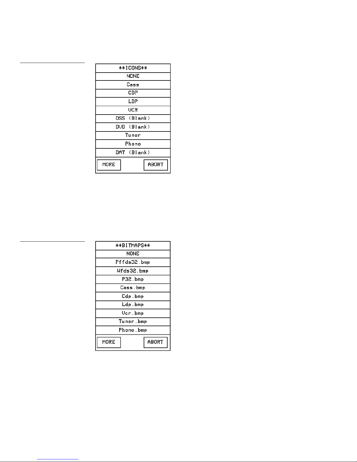
Figure 153
ICONS menu
• BITMAP OFF Opens the BITMAPS menu (Figure 154) where you can se-
lect the bitmap to appear on the Off-state of the button. Select MORE to view
more bitmap files or ABORT to exit and return to the Text/image page.
BITMAP ON Opens the BITMAPS menu (Figure 154) where you can se-
•
lect the bitmap to appear on the On-state of the button. Select MORE to view
more bitmap files or ABORT to exit and return to the Text/image page.
Figure 154
BITMAPS menu
• SET TEXT ALIGNMENT Sets the text alignment on the button. Figure 155
shows the SET TEXT ALIGNMENT menu textually for each button. The text
references do not appear on the actual Set Text Alignment page.
88 Touch Panel Program Reference Color Active-Matrix LCD Mini-Touch Panels
Page 97
Figure 155
SET TEXT ALIGNMENT page
• MAKE ON SAME AS OFF Copies the Off-state text, icon, and/or bitmap
settings to the On-state buttons.
EXIT SAVE CHANGE Saves the current settings, exits the Text/image
•
page, and returns to the current page.
EXIT NO CHANGE Cancels the current settings and returns to the current
•
page.
Properties
Select PROPERTIES and a button to open the Properties page (Figure 156). Then, you
can set the border style, channel/variable options, button type, button options, flip
type, string, and channel Off/On attributes.
Figure 156
Properties page
Color Active-Matrix LCD Mini-Touch Panels Touch Panel Program Reference 89
Page 98

Figure 157
BUTTON BORDER menus
external pushbuttons.
Note
This feature doesn’t apply to
• BORDER Opens the BUTTON BORDER menu (Figure 157) where you
select the border style. Figure 158 shows the border names and styles.
Figure 158
Border names and styles
Border names and styles
Name Style Name Style Name Style
No border
No border
special
Single line Double
Double line 3D rectangle 1 3D round 2
Triple line 3D rectangle 2 3D neon 1
Single
rounded
Double
rounded
Double line 2 3D rectangle 1
Double line 3 3D rectangle 2
3D round 1
shadow
3D round 1 3D neon 2
3D round 2 3D neon blue
Single raised 3D neon 1 3D neon green
90 Touch Panel Program Reference Color Active-Matrix LCD Mini-Touch Panels
Page 99

Note
formation.
130, and 131.
Touch panel
Base devices
DEVICE #1
CHAN #1
CHAN #25
CHAN #50
CHAN #100
DEVICE #2
DEVICE #3
DEVICE #4
CHAN = 1-255
CHAN #135
CHAN #149
CHAN #200
CHAN #255
ranges
All new buttons are automatically set to Double-Raised.
Figure 159
Device and channel assignments
Border names and styles (Cont.)
Name Style Name Style Name Style
Double raised 3D neon 2 Single dia-
mond
Triple Raised 3D neon blue Double dia-
mond
The channel code allows a button to have AXCESS code statements like Push and
Release associated with specific functions. Figure 159 shows the relationship between
the device and channel numbers. Each device can have a channel range from 1 to 255
per device.
Note
In order to use channels for
DEV 2 through 4, DEVICE
USED on the Protected Setup
page must be set to 2 through
4 respectively. Refer to the
Protected Setup Page: Device
used subsection for more in-
Note
If the value in the DEVICE
USED button is set to 4 and
Base Device Number is 128,
the Central Controller recognizes bus devices 128, 129,
DEVICE = 1-4
Channel code
• CHANNEL − DEV Referred to as the Base device number, The device range
(from 1–4) doesn’t represent actual hardware devices but instead provides
up to four different touch panel bus devices that can be assigned with channel values from 1 through 255. Opens the keypad where you set the device
number for the current button or touch panel page.
CHANNEL − CHAN Referred to as the channel code number and repre-
•
sents the button channel assignments recognized by the Central Controller.
Opens the keypad where you set the channel code for the current button.
The channel code range is from 1 through 255. Record the channel code settings if you want to create duplicate buttons and functions on another page.
If AUTO ASSIGN is enabled in the Protected Setup page, the touch panel
prompts you to automatically or manually assign the channel code. Select
YES to allow the touch panel to assign the lowest unused channel number.
Color Active-Matrix LCD Mini-Touch Panels Touch Panel Program Reference 91
Page 100

As shown in Figure 160, the upper-left corner of a button shows a base device num-
PANEL
3, 132
1,255
Button
Slider
number
device number
2, 255
2, 1
number
Text channel
Level channel
number
slider example
firmware.
button types).
ber followed by a channel code number. The bottom-right corner of a button shows
the variable text number followed by the variable text channel.
Figure 160
Function show button and
Note
Refer to the Function show
subsection for more information.
Note
This allows up to 1020 button
combinations in the new G3
Base device
LIGHT
Variable text
Channel code
Level device
The new G3 firmware is designed to allow you up to 255 channels per device layer.
VAR TEXT − DEV Opens the keypad where you set the device number for
•
the current button and touch panel page. The device range is 1 through 4.
VAR TEXT − CHAN Opens the keypad where you set the variable text
•
channel code for the current button. The channel code range is from 1
through 255. Record the channel code settings if you want to create duplicate
buttons and their functions on another page. If AUTO ASSIGN is enabled in
the Protected Setup page, the touch panel prompts you to automatically or
manually assign the channel code. Select YES to allow the touch panel to
automatically assign the lowest available channel number.
LEVEL − DEV Opens the keypad where you set the device number for the
Note
Level settings apply only to
Joystick buttons (Joystick and
Video Joystick button types),
and Bargraph buttons (Horizontal and Vertical Bargraph
•
current button and touch panel page. The device range is 1 through 4.
LEVEL − NUM Opens the keypad where you set the number codes for the
•
current button. The number code range is 1 through 8 except for bargraphs
and joysticks, where the range is from 1 through 7. Joysticks actually use two
level numbers. The first is for the X-axis and the second is for the Y-axis. You
only need to specify the first level. Record the channel code settings if you
want to create duplicate buttons and their functions on another page.
BUTTON TYPE Opens the BUTTON TYPE menus (Figure 161) where you
•
select the button type. After you select a button type, the Properties page resets with specific options according to that button type. For example, if you
select the button type GENERAL, the BUTTON OPTIONS, FLIP, and
STRING operation bars appear in the Properties page.
92 Touch Panel Program Reference Color Active-Matrix LCD Mini-Touch Panels
 Loading...