

Page 1
Color Active-Matrix LCD Mini-Touch Panels
t a k e c o n t r o l
(Firmware version G2 or lower)
Instruction Manual
Page 2

Limited Warranty and Disclaimer
AMX Corporation warrants its products to be free from defects in material and
workmanship under normal use for a period of three years from date of purchase
from AMX, with the following exceptions. Electroluminescent and LCD control
panels are warranted for a period of three years, except for the display and touch
overlay components, which are warranted for a period of one year. Disk drive
mechanisms, pan/tilt heads, codecs, power supplies, modifications, MX Series
products, and KC Series products are warranted for a period of one year. Unless
otherwise specified, OEM and custom products are covered for a period of one year.
AMX software products are warranted for a period of 90 days. Batteries and
incandescent lamps are not covered.
This warranty extends to products purchased directly from AMX or an authorized
AMX dealer. Consumers should inquire from selling dealer as to the nature and
extent of the dealer’s warranty, if any.
AMX is not liable for any damages caused by its products or for the failure of its
products to perform, including any lost profits, lost savings, incidental damages, or
consequential damages. AMX is not liable for any claim made by a third party or
made by you for a third party.
This limitation of liability applies whether damages are sought, or a claim is made,
under this warranty or as a tort claim (including negligence and strict product
liability), a contract claim, or any other claim. This limitation of liability cannot be
waived or amended by any person. This limitation of liability will be effective even
if AMX or an authorized representative of AMX has been advised of the possibility
of any such damages. This limitation of liability, however, will not apply to claims
for personal injury.
Some states do not allow a limitation of how long an implied warranty lasts. Some
states do not allow the limitation or exclusion of incidental or consequential
damages for consumer products. In such states, the limitation or exclusion of the
Limited Warranty may not apply to you. This Limited Warranty gives you specific
legal rights. You may also have other rights that may vary from state to state. You
are advised to consult applicable state laws for full determination of your rights.
EXCEPT AS EXPRESSLY SET FORTH IN THIS WARRANTY, AMX MAKES NO OTHER WARRANTIES,
EXPRESSED OR IMPLIED, INCLUDING ANY IMPLIED WARRANTIES OF MERCHANTABILITY OR
FITNESS FOR A PARTICULAR PURPOSE. AMX EXPRESSLY DISCLAIMS ALL WARRANTIES NOT
STATED IN THIS LIMITED WARRANTY. ANY IMPLIED WARRANTIES THAT MAY BE IMPOSED BY
LAW ARE LIMITED TO THE TERMS OF THIS LIMITED WARRANTY.
Page 3

Table of Contents
Introduction ............................................................................ 1
Overview 1
Features 2
Applications 2
What's in this Manual 3
Installing Mini-Touch Panels ................................................. 5
Overview 5
Mounting the Mini-Touch Panels 5
AXU-MCA (/PB), AXU-MCV (/PB),
and low profile back box 5
AXU-MCA (/PB), AXU-MCV (/PB),
and BB-MTP UniMount enclosure
(solid surfaces) 7
AXU-MCA (/PB), AXU-MCV (/PB), and
BB-MTP UniMount enclosure
(plasterboard) 9
AXM-MCA (/PB) or AXM-MCV (/PB)
(rack mount) 11
Wiring the Mini-Touch Panels 12
Preparing captive wires 13
Wiring guidelines 13
Using the TiltScreen mini-XLR connector
for AXlink data and power 14
Using the TiltScreen mini-XLR connector
for AXlink and an external 12 VDC
power supply 14
Using the UniMount and rack-mount
AXlink connector for data and power 15
Using the UniMount and rack-mount
AXlink connector for data and an
external 12 VDC power supply 15
Using the UniMount and rack-mount
4-pin header for mouse control 16
Cleaning the Touch Overlay 17
Color Active-Matrix LCD Mini-Touch Panels Table of Contents i
Page 4

Mini-Touch Panel Basics ..................................................... 19
Overview 19
Mini-Touch Panel Pages 19
Standard Buttons 20
General Buttons 20
Message bar 20
Editor bar 21
Selection button 21
Information button 21
Adjustment button 22
Keypad buttons 22
Page menu buttons 23
Decision buttons 23
Status buttons 24
Keyboards 24
Designing a Mini-Touch Panel Page ................................... 29
Overview 29
Activate the Editor Bar 29
Create a Page 31
Add a page 31
Go to NEW PAGE 33
Create a Button 34
Add a button 34
Resize the button 35
Button Attributes 36
Set the button attributes 36
Set the border 37
Set the channel code 38
Set the page flip 38
Add Text 39
Add text to a button 39
Create a Joy Stick 40
Add a joy stick on a page 40
Set the joy stick attributes 41
Set the level code 42
Create a Bargraph 43
Add a bargraph to a page 43
Set the bargraph attributes 44
Set the level code 45
Set the Video Display 45
ii Table of Contents Color Active-Matrix LCD Mini-Touch Panels
Page 5

Link the New Page to the Main Page 47
Close the Editor Bar 49
Exit editor mode 49
Mini-Touch Panel Program Reference................................. 51
Overview 51
Setup Page 51
Open the Setup Page 52
Buttons 52
Beep 52
LCD timer 53
Serial number, AXlink, and vX.XX 53
SmartPack 54
WAVE 55
Set time and date 57
Double beep 58
Protected setup 58
Set background 59
Brightness 60
Protected Setup Page 61
Open the Protected Setup Page 61
Protected Setup Page Buttons 62
Editor 62
Setup password 63
Auto assign 63
Set serial 64
Set device 66
Page password 67
Power up page 67
Calibrate 68
Page tracking 68
LCD timer message 69
Timer BRT 72
Editor Bar 72
Button Menu Options 73
Add 74
Move 74
Copy image 74
Delete 75
Resize 75
Edit text 76
Color Active-Matrix LCD Mini-Touch Panels Table of Contents iii
Page 6

Attributes 79
Save 83
Paste 83
Page Menu Options 83
Add 84
Copy 85
Rename 86
Delete 87
Go to 87
Passwd pg flip 88
Print 89
Page color 90
Icons Menu Options 90
Time 91
Date 91
E timer 91
16 char term 92
32 char term 92
Vertical graph 92
Icon feedback 95
Joy stick 97
Drawings 100
Brightness 100
Video Setup 101
System Menu Options 102
Clear buttons 103
Clear drawings 103
Memory 104
Send file 105
Receive file 106
Move edit bar 107
Print 107
Function map 108
Function show 109
Set Defaults 110
iv Table of Contents Color Active-Matrix LCD Mini-Touch Panels
Page 7

AXCESS Programming....................................................... 113
Overview 113
System Send_Commands 113
Color Numbers 119
Color Send_Commands 119
Variable Text Send_Commands 122
WavePack Button Attribute String_Commands124
Replacing the Lithium Batteries ........................................ 125
Overview 125
AXT-MCA (/PB) and AXT-MCV (/PB) 125
AXU-MCA (/PB), AXU-MCV (/PB),
AXM-MCA (/PB), and AXM-MCV (/PB) 127
512K Memory Upgrade ...................................................... 129
Operation 129
AXT-MCA (/PB) and AXT-MCV (/PB) 129
AXU-MCA (/PB), AXU-MCV (/PB),
AXM-MCA (/PB), and AXM-MCV (/PB) 130
Color Guidelines................................................................. 133
Overview 133
Colors 133
Specifications..................................................................... 135
Overview 135
AXT-MCA (/PB) and AXT-MCV (/PB) 135
AXU-MCA (/PB) and AXU-MCV (/PB) 136
AXM-MCA (/PB) and AXM-MCV (/PB) 137
Technical Support .............................................................. 139
Overview 139
Index.................................................................................... 141
Overview 141
Color Active-Matrix LCD Mini-Touch Panels Table of Contents v
Page 8

vi Table of Contents Color Active-Matrix LCD Mini-Touch Panels
Page 9
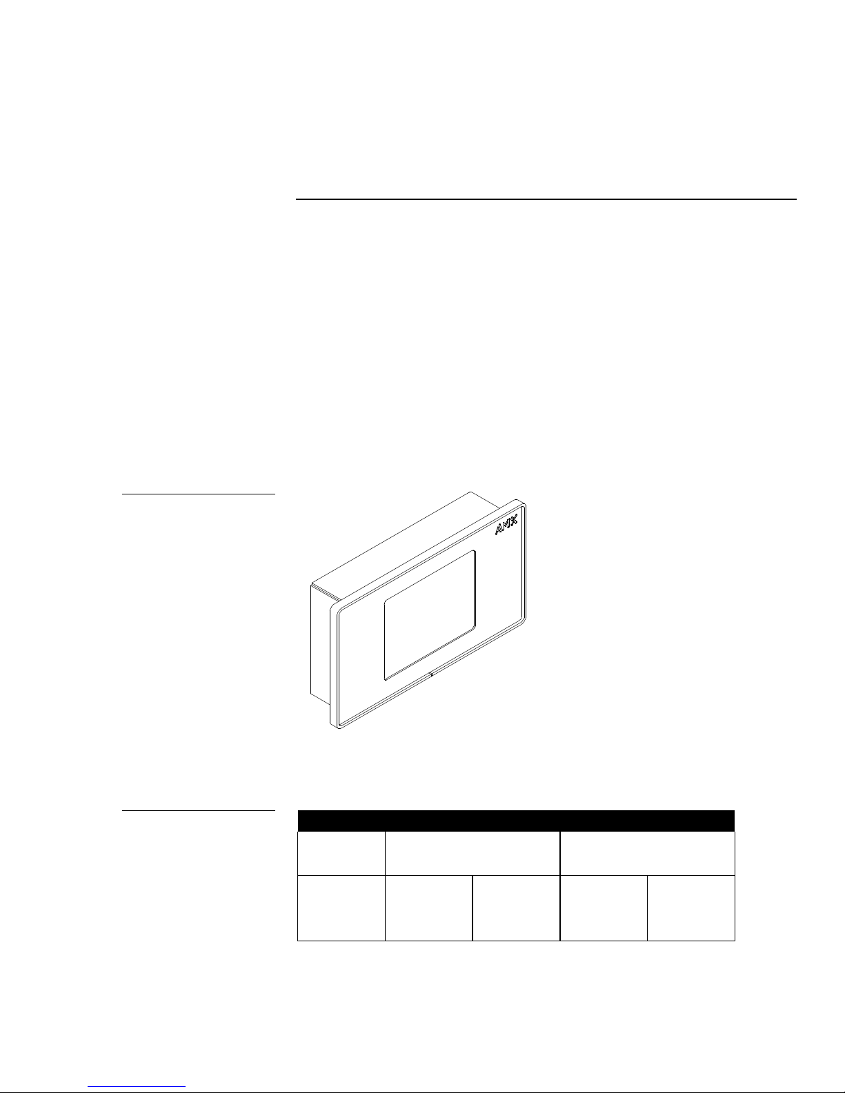
Figure 1
AXU-MCA UniMount minitouch panel
Introduction
Overview
The color active-matrix mini-touch panels contain a dedicated 256-color, 320 x 240
(HV) pixel, liquid crystal display (LCD). The mini-touch panels are self-contained
enclosures that use a microprocessor to control a wide range of audiovisual
products. Special mini-touch panel options include a video input port that is PALand NTSC-compatible, and 12 pushbuttons (6 pushbuttons on each side) that can be
programmed to perform specific control operations. With the mini-touch panel
operating system, you can create custom pages with buttons, icons, sliders,
bargraphs, and imported logos and drawings. You can also use the TPDOC or
TPDesign custom touch panel design programs AMX offers to enhance your minitouch panel designs. Figure 1 shows an AXU-MCA UniMount mini-touch panel.
Figure 2
Color mini-touch panel types
and product names
Color Active-Matrix LCD Mini-Touch Panels Introduction 1
Figure 2 lists the mini-touch panel types and product names described in this
manual.
Color mini-touch panel types and product names
Non-Video Panels Video Panels
Panel types Standard Pushbuttons Standard Pushbuttons
TiltScreen AXT-MCA AXT-MCA/PB AXT-MCV AXT-MCV/PB
UniMount AXU-MCA AXU-MCA/PB AXU-MCV AXU-MCV/PB
Rack mount AXM-MCA AXM-MCA/PB AXM-MCV AXM-MCV/PB
Page 10
Features
Lighting
Mini-touch panel features include:
• 5" diagonal display—2.8" x 3.9" (71 mm x 97 mm)
• 256-color active matrix 320 x 240 (HV) pixel LCD
• 12 programmable pushbuttons (6 on each side)
• Microsoft or Logitech mouse compatible (UniMount and rack-mount models
only)
• Panel programming, screens, and drawings that can be uploaded and
downloaded with TPDOC (MS-DOS) or TPDesign (Windows) touch panel
software programs.
• PAL- and NTSC-compatible video input port (optional)
• Internal 4-pin header for mouse control (UniMount and rack-mount models
only)
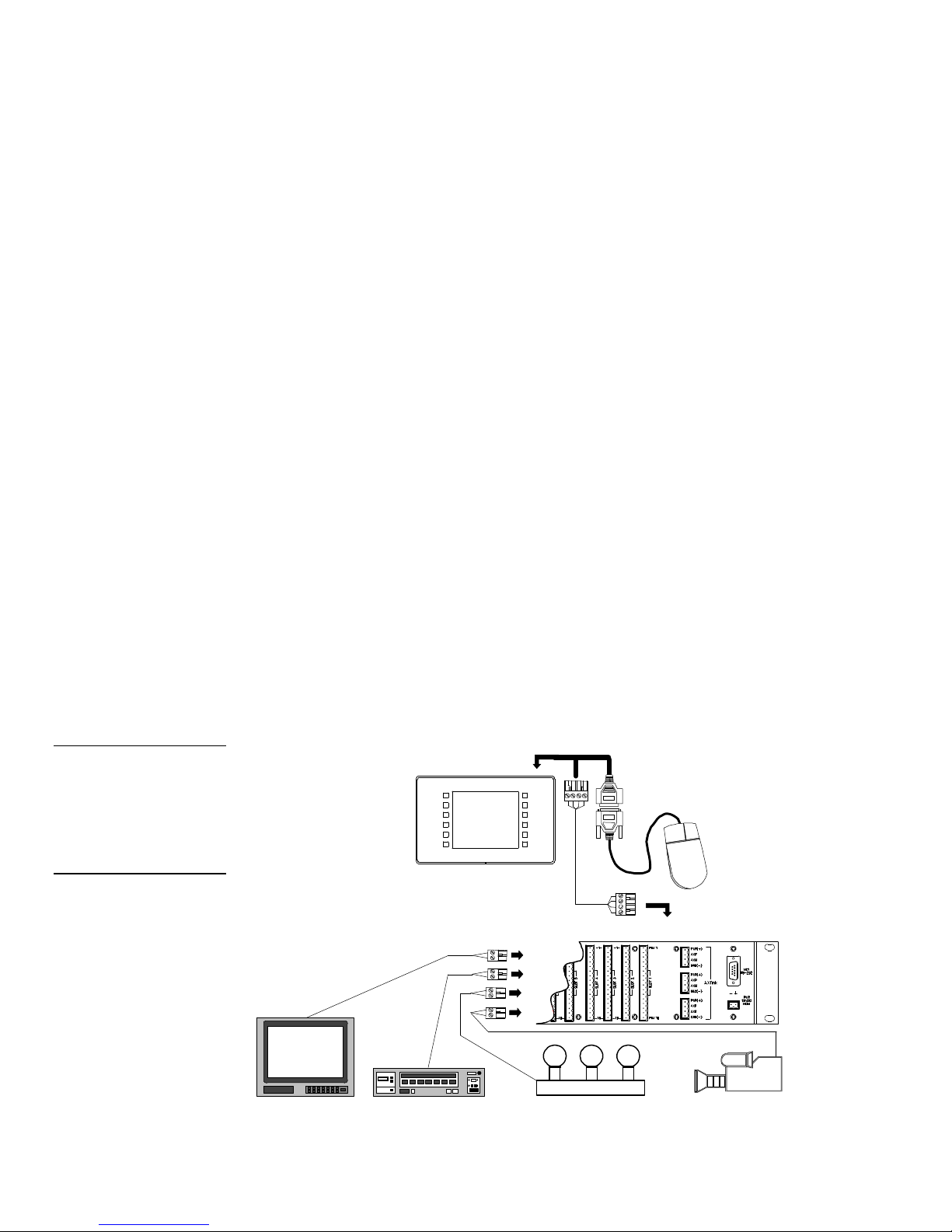
Applications
The mini-touch panels can control a wide variety of equipment connected to an
AXCESS Control System, serial mouse, or a combination of both. Figure 3 shows
how you can use the AXU-MCA control capabilities with an AXCESS Control
System. The mouse shown in Figure 3 is optional.
Figure 3
Sample AXU-MCA and
AXCESS Control System
Note
The mouse can be used to
design mini-touch panel pages
and then removed prior to
installation.
Television VCR
2 Introduction Color Active-Matrix LCD Mini-Touch Panels
AXU-MCA
Mouse (optional)
port
AXlink cable
AXCESS CardFrame
Camera
Page 11

What's in this Manual
This manual provides basic instructions on how to use the mini-touch panel
operating system, and installation, basic elements, basic page designs, reference
information, AXCESS programming, battery replacement procedures, 512K memory
upgrade, color guidelines, specifications, and technical support information. If you
are not familiar with the AMX mini-touch panel operating system, read through the
Mini-Touch Panel Basics section and create touch panel pages and objects. If you are
an experienced AMX touch panel page designer, read through the Mini-Touch Panel
Program Reference section for complete descriptions of all mini-touch panel
operations. Section titles and descriptions contained in this manual include:
• Installing the Mini-Touch Panel Installation, wiring, and cleaning
instructions.
• Mini-Touch Panel Basics Basic elements associated with the mini-touch
panel operating system such as button types, message and editor selection
bars, and keyboards.
• Designing a Mini-Touch Panel Page Step-by-step instructions to create a
mini-touch panel page, button, joy stick, and bargraph.
• Mini-Touch Panel Program Reference Describes all mini-touch panel
operations.
• AXCESS Programming Lists AXCESS system commands used to integrate
mini-touch panel features such as color settings, page flips, and variable text
into an AXCESS Control System.
• Replacing the Lithium Batteries Shows how to replace the lithium
batteries in the mini-touch panel.
• 512K Memory Upgrade Step-by-step instructions to install an optional
512K integrated circuit (IC) into the mini-touch panel.
• Color Guidelines Helpful hints you can use to choose the best mini-touch
panel colors.
• Specifications Mini-touch panel dimensions, LCD screen dimensions,
weight, power, memory, enclosure type and color, accessories, and software
programs.
Color Active-Matrix LCD Mini-Touch Panels Introduction 3
Page 12

• Technical Support Helpful hints you can use to check panel wiring, correct
a software program problem, and the numbers to call for AMX technical
support.
4 Introduction Color Active-Matrix LCD Mini-Touch Panels
Page 13
Installing Mini-Touch Panels
Overview
The section describes how to mount, wire, and clean mini-touch panels.
Mounting the Mini-Touch Panels
The following describes how to mount the UniMount and rack mount mini-touch
panels. The TiltScreen mini-touch panel can be mounted on any flat surface.
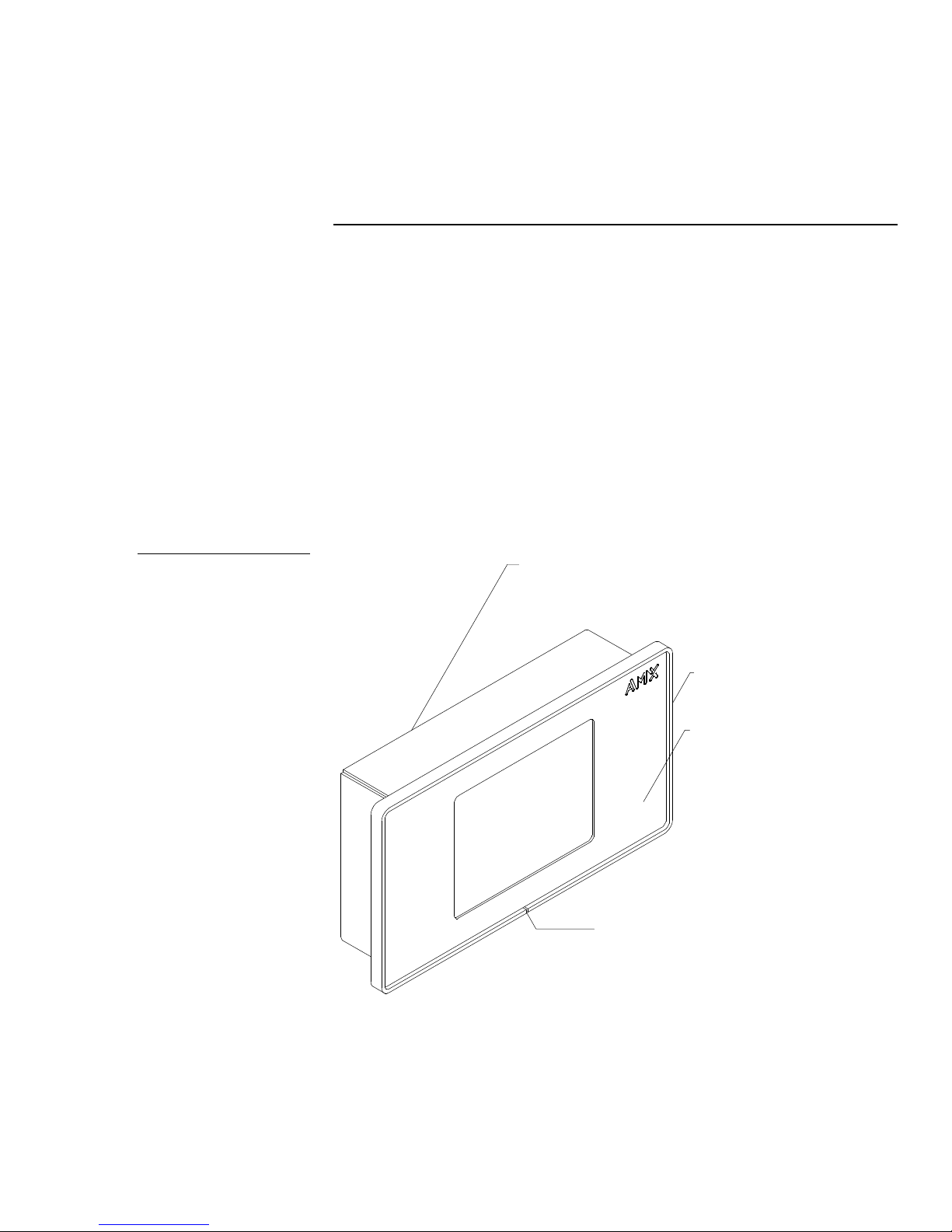
AXU-MCA (/PB), AXU-MCV (/PB), and low profile back box
Mount the AXU-MCA (/PB), AXU-MCV (/PB), and low profile back box. Figure 4
shows the AXU-MCA and low profile back box.
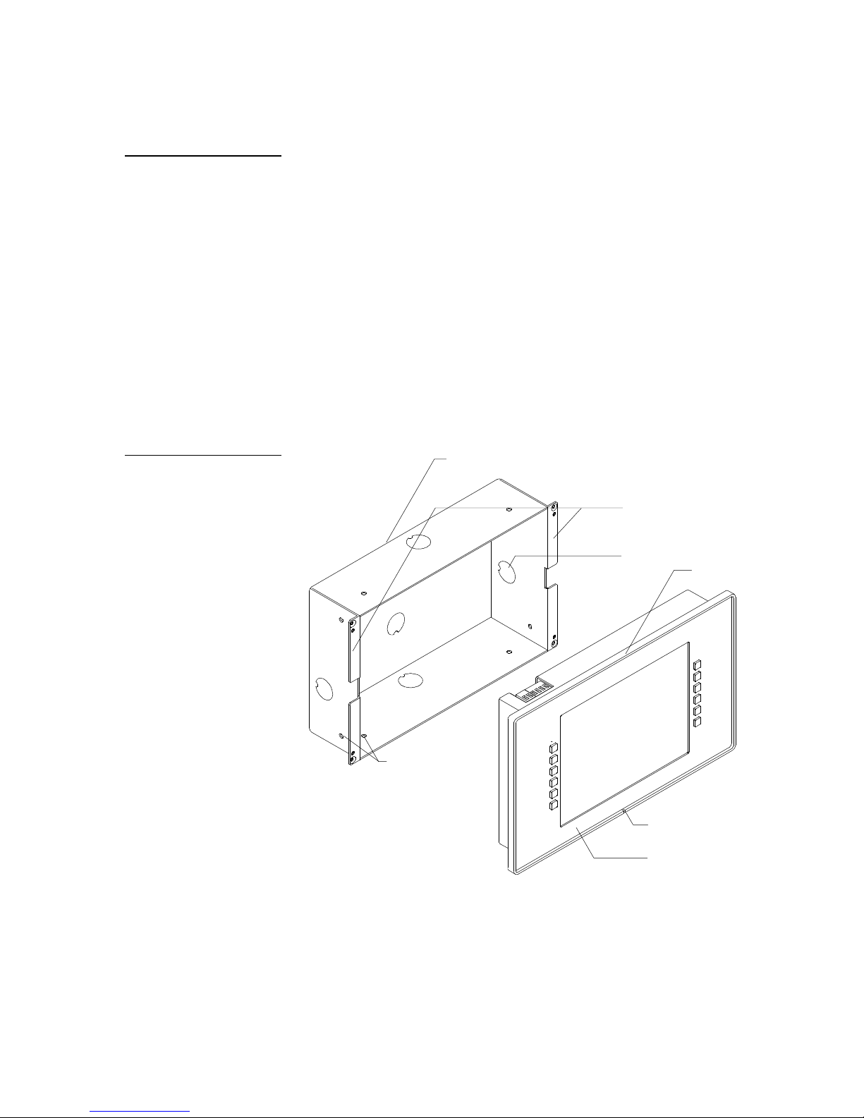
Figure 4
AXU-MCA and low profile back
box
Low profile back box
AXU-MCA bezel
Engraved overlay
Release slot
Color Active-Matrix LCD Mini-Touch Panels Installing Mini-Touch Panels 5
Page 14
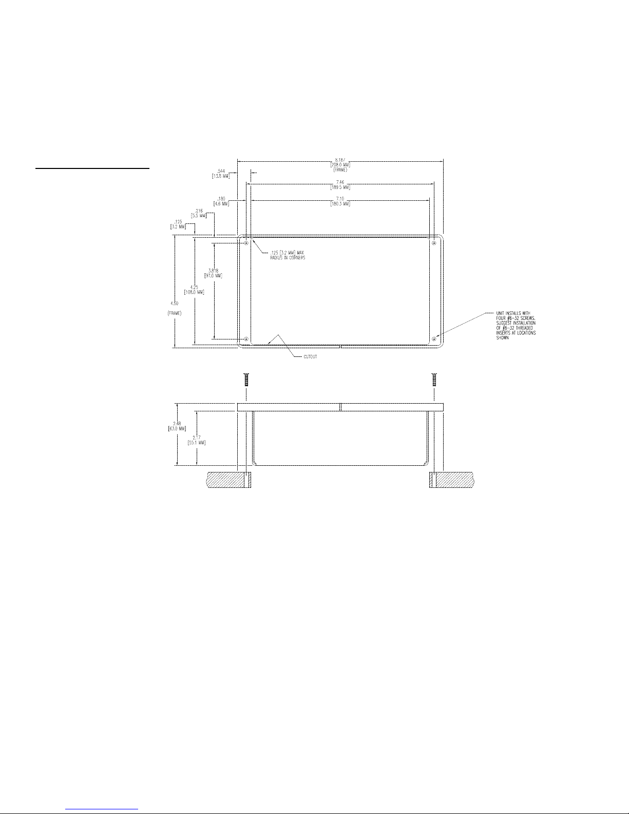
Figure 5
AXU-MCA (/PB), AXU-MCV
(/PB), and low profile back box
cutout dimensions
1. Make a cutout in the surface according to the dimensions shown in Figure 5 for
a low profile back box.
2. Insert a flat-blade screwdriver into the release slot on the mini-touch panel's
bezel and remove the engraved overlay.
3. Place the mini-touch panel into the cutout and mark the screw insert positions
as shown in Figure 5.
4. Remove the mini-touch panel and drill four #6-32 insert holes. Then, place a
threaded insert into each hole.
5. Attach the AXlink and optional RCA video connectors to the mini-touch panel.
Refer to Wiring the Mini-Touch Panels for wiring diagrams and pinout
descriptions.
6 Installing Mini-Touch Panels Color Active-Matrix LCD Mini-Touch Panels
Page 15
Release slot
BB-MTP UniMount enclosure
holes
Note
The mini-touch panel must be
installed with the release slot
located at the bottom.
Figure 6
6. Fasten the mini-touch panel and low profile back box to the surface using the
#6-32 machine screws supplied with the enclosure.
7. Insert the engraved overlay back into the bezel.
8. Connect the AXlink wiring to the AMX Control System, and the optional video
wiring to the video source. The mini-touch panel will beep when you apply
power.
AXU-MCA (/PB), AXU-MCV (/PB), and BB-MTP UniMount enclosure (solid
surfaces)
Mount the AXU-MCA (/PB), AXU-MCV (/PB), and BB-MTP UniMount enclosure
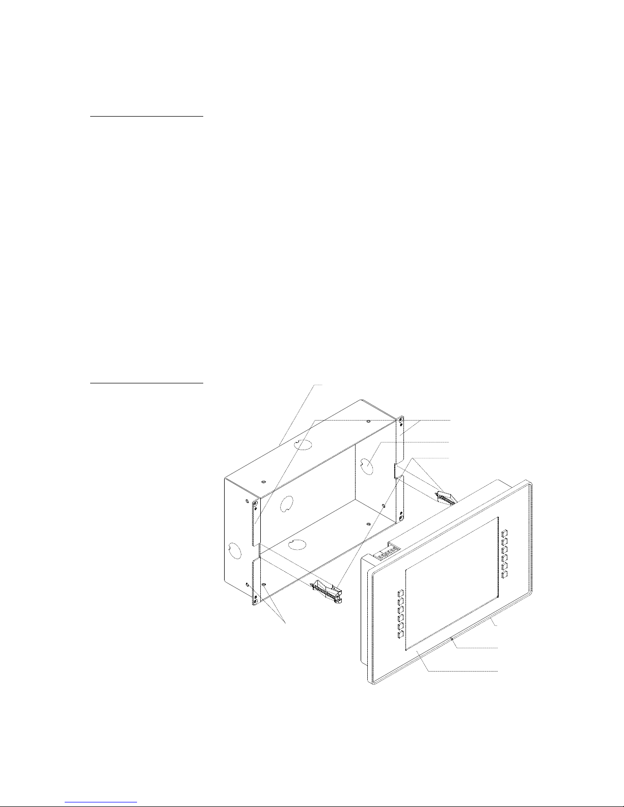
into a solid surface. Figure 6 shows the AXU-MCA/PB and BB-MTP UniMount
enclosure for solid surfaces.
AXU-MCA/PB and BB-MTP
UniMount enclosure for solid
surfaces
Solid surface mounting
flanges
Knockout
AXU-MCA/PB bezel
Stud mounting
Engraved overlay
Color Active-Matrix LCD Mini-Touch Panels Installing Mini-Touch Panels 7
1. Cut the solid surface according to the cutout dimensions shown in Figure 7.
2. Insert a flat-blade screwdriver into the release slot on the mini-touch panel's
bezel and remove the engraved overlay.
Page 16
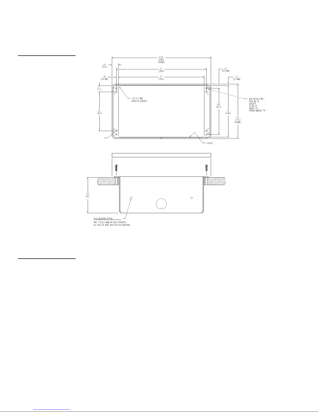
Figure 7
Mini-touch panel and BB-MTP
cutout dimensions
3. Lay the mini-touch panel facedown onto a soft cloth and remove the four screws
from the low profile back box. Remove the back box and discard.
Note
The BB-MTP can also be
mounted to wood or metal
studs using the pre-drilled stud
mounting holes.
4. Place the BB-MTP into the cutout and mark the threaded insert positions as
shown in Figure 7.
5. Remove the BB-MTP and drill eight holes as shown in Figure 7. Then, place #6-
32 threaded inserts into the four holes marked ‘B’ in the cutout dimensions
illustration.
6. Disconnect the AXlink connector from the AMX Control System, and the
optional video wiring from the video source.
7. Remove one or more knockouts to accommodate the wiring as required.
8. Thread the incoming AXlink and video wiring through the BB-MTP knockout.
8 Installing Mini-Touch Panels Color Active-Matrix LCD Mini-Touch Panels
Page 17
Release slot
BB-MTP UniMount enclosure
holes
Note
The mini-touch panel must
always be installed with the
release slot located at the
bottom.
Figure 8
9. Fasten the BB-MTP to the solid surface with the mounting screws supplied with
the enclosure.
10. Connect the AXlink and video wiring to the mini-touch panel. Refer to Wiring
the Mini-Touch Panels for wiring diagrams and pinout descriptions.
11. Fasten the mini-touch panel to the BB-MTP with the #6-32 screws provided with
the enclosure.
12. Insert the engraved overlay back into the bezel.
13. Connect the AXlink wiring to the AMX Control System, and video wiring to the
video source. The mini-touch panel will beep when you apply power.
AXU-MCA (/PB), AXU-MCV (/PB), and BB-MTP UniMount enclosure
(plasterboard)
Mount the AXU-MCA (/PB), AXU-MCV (/PB), and BB-MTP into a plasterboard
surface (or equivalent). Figure 8 shows the AXU-MCA/PB and BB-MTP UniMount
enclosure for plasterboard.
AXU-MCA/PB and BB-MTP
UniMount enclosure for
plasterboard
Stud mounting
Plasterboard surfacemounting flanges
Knockout
Expansion clips
AXU-MCA/PB bezel
Engraved overlay
Color Active-Matrix LCD Mini-Touch Panels Installing Mini-Touch Panels 9
Page 18

Figure 9
Mini-touch panel and BB-MTP
cutout dimensions
1. Cut the surface according to the cutout dimensions shown in Figure 9.
2. Insert a flat-blade screwdriver into the release slot on the mini-touch panel’s
bezel and remove the engraved overlay.
3. Lay the mini-touch panel facedown onto a soft cloth and remove the four screws
from the low profile back box. Remove the back box and discard.
4. Place the BB-MTP into the cutout and mark the threaded insert positions as
shown in Figure 9.
5. Remove the BB-MTP and drill four #6-32 insert holes. Then, place a threaded
insert into each hole.
10 Installing Mini-Touch Panels Color Active-Matrix LCD Mini-Touch Panels
Page 19
6. Disconnect the AXlink connector from the AMX Control System, and the
optional video wiring from the video source.
7. Thread the incoming AXlink and video wiring through the BB-MTP knockout.
Note
The mini-touch panel must be
installed with the release slot
located at the bottom.
Figure 10
AXM-MCA/PB and AC-RK
rack kit for an electronic
equipment rack
8. Fasten the BB-MTP to the plasterboard using the expansion screws supplied
with the enclosure.
9. Connect the AXlink and video wiring to the mini-touch panel. Refer to Wiring
the Mini-Touch Panels for wiring diagrams and printout descriptions.
10. Fasten the mini-touch panel to the BB-MTP with the #6-32 screws supplied with
the enclosure.
11. Insert the engraved overlay back into the bezel.
12. Connect the AXlink wiring to the AMX Control System, and video wiring to the
video source. The mini-touch panel will beep when you apply power.
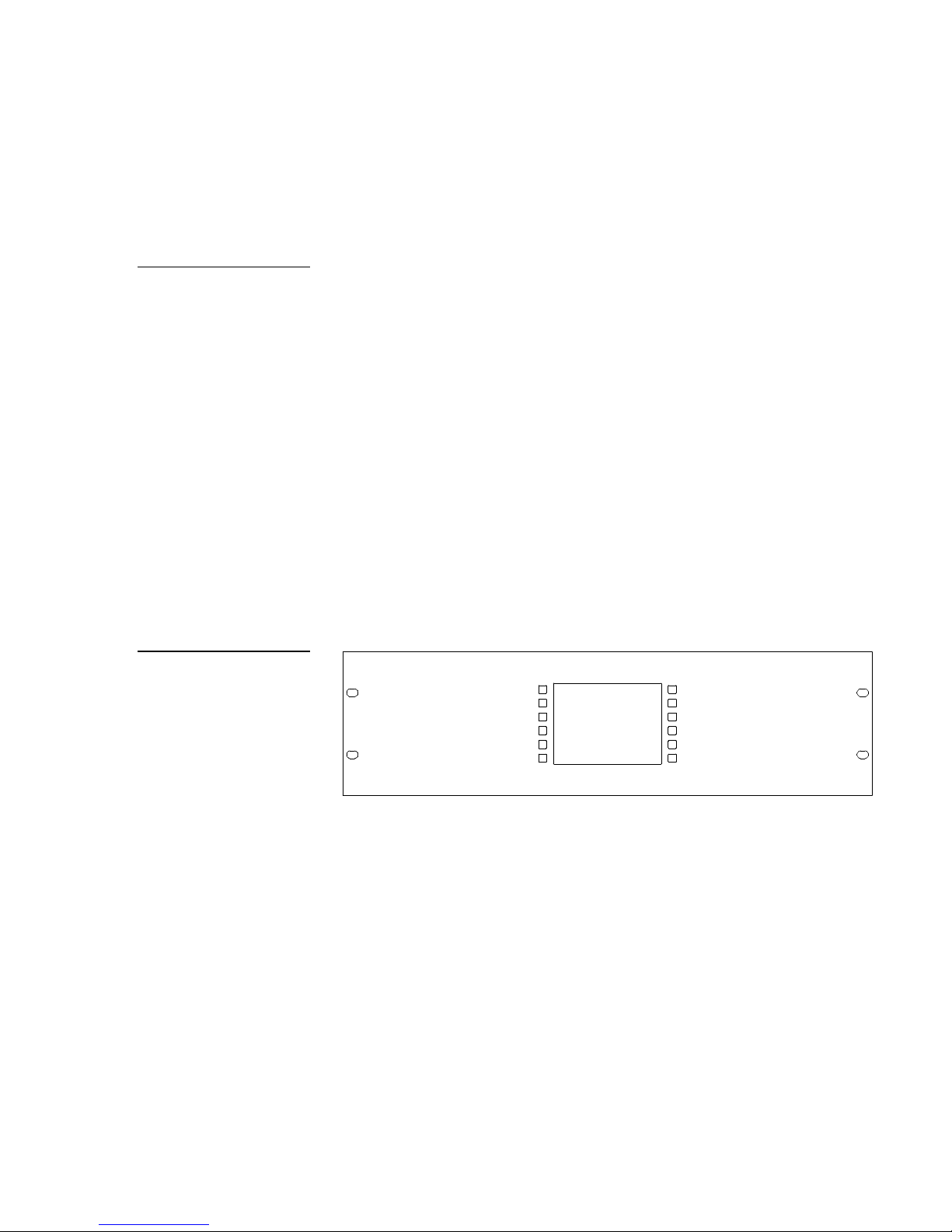
AXM-MCA (/PB) or AXM-MCV (/PB) (rack mount)
Mount the AXM-MCA (/PB), AXM-MCV (/PB), and AC-RK rack kit into an
electronic equipment rack. Figure 10 shows the AXM-MCA/PB and AC-RK
Accessory Rack Kit for an equipment rack.
Color Active-Matrix LCD Mini-Touch Panels Installing Mini-Touch Panels 11
1. Thread the incoming AXlink and video wiring through the opening in the
equipment rack.
2. Disconnect the AXlink connectors from the AMX Control System, and the
optional video wiring from the video source.
3. Connect the AXlink and video wiring to the mini-touch panel circuit card. Refer
to Wiring the Mini-Touch Panels for wiring diagrams and pinout descriptions.
4. Insert the mini-touch panel into the equipment rack. Line up the top-left and
bottom-right screw holes and start the #6-32 screws. Then, start the bottom-left
and top-right screws. Tighten all the screws after you start all the screws.
Page 20
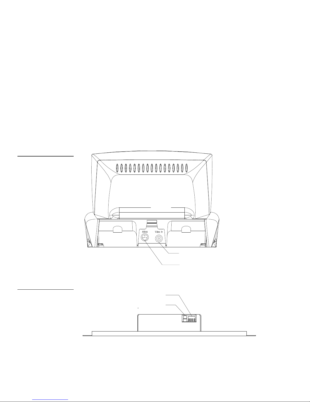
Figure 11
TiltScreen mini-touch panel
connectors (rear view)
5. Connect the AXlink wiring to the AMX Control System, and video wiring to the
video source. The mini-touch panel will beep when you apply power.
Wiring the Mini-Touch Panels
The TiltScreen mini-touch panels use a mini-XLR (male) connector for power and
data communications, and an optional RCA connector to display PAL- and NTSCcompatible video. The UniMount and rack-mount mini-touch panels use a 4-pin
(male) AXlink connector for power and data, and an optional RCA connector to
display PAL- and NTSC-compatible video. Figure 11 shows the rear panel AXlink
and optional RCA connectors on the TiltScreen mini-touch panels. Figure 12 shows
the rear panel AXlink and optional RCA connector on the rack-mount mini-touch
panel.
Figure 12
Rack-mount mini-touch panel
connectors (top view)
Rear view
RCA video connector (optional)
Mini-XLR 4-pin (male) AXlink and
power connector
4-pin (male) AXlink connector
RCA video connector (optional)
Top view
12 Installing Mini-Touch Panels Color Active-Matrix LCD Mini-Touch Panels
Page 21

Preparing captive wires
Caution
Do not connect power to the
mini-touch panel until the wiring
is complete. If you are using a
12 VDC power supply, apply
power to the mini-touch panel
only after installation is
complete.
Caution
Do not over-torque the screw.
Doing so can bend the seating
pin and damage the connector.
You will need a wire stripper, soldering iron, and flat-blade screwdriver to prepare
and connect the captive wires.
1. Strip 0.25 inch of wire insulation off all wires and apply a light coat of solder to
the ends using a soldering iron.
2. Insert each wire into the appropriate opening on the connector according to the
wiring diagrams and connector types described in this section.
3. Turn the flat-blade screws clockwise to secure the wire in the connector.
Wiring guidelines
Mini-touch panels require regulated 12 VDC power to operate properly. The
AXCESS Control System supplies power via the AXlink cable. The maximum wiring
distance between the control system and mini-touch panel is determined by power
consumption, supplied voltage, and the wire gauge used for the cable. Figure 13 lists
wire sizes and the maximum lengths allowable between the mini-touch panel and
control system. The maximum wiring lengths for using AXlink power are based on a
minimum of 13.5 volts available at the control system’s power supply.
Figure 13
Wiring guidelines
Wiring guidelines
Wire size Maximum wiring
length
18 AWG 167 feet
20 AWG 106 feet
22 AWG 66 feet
24 AWG 41 feet
If you install the mini-touch panel farther away from the control system than
recommended in Figure 13, connect an external 12 VDC power supply to the
TiltScreen, UniMount, and rack-mount mini-touch panels according to the wiring
diagrams and pinout descriptions in this section.
Color Active-Matrix LCD Mini-Touch Panels Installing Mini-Touch Panels 13
Page 22
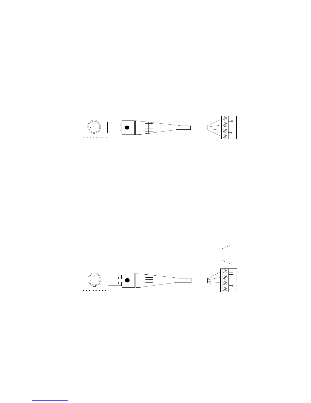
Using the TiltScreen mini-XLR connector for AXlink data and power
2
1
PWR + (RED)
3
4
234
1 - GND - (BLK)
2 - AXM (GRN)
2
1
AXM (GRN)
AXP (WHT)
3
4
PWR + (RED)
234
2 - AXM (GRN)
GND - (BLK)
Connect the control system’s AXlink connector to the mini-XLR connector (male) on
the rear panel of the TiltScreen mini-touch panel for data and 12 VDC power as
shown in Figure 14.
Figure 14
Mini-XLR connector-to-control
system wiring diagram
Figure 15
Mini-XLR connector to external
12 VDC power supply, and
control system wiring diagram
4-pin mini-XLR
connector
GND - (BLK)
1
4 - PWR + (RED)
3 - AXP (WHT)
Control system
AXM (GRN)
AXP (WHT)
Using the TiltScreen mini-XLR connector for AXlink and an external 12
VDC power supply
Connect the control system’s AXlink connector to the mini-XLR connector and
external 12 VDC power supply to the rear panel of the mini-touch panel as shown in
Figure 15.
12 VDC power supply
1
4 - PWR + (RED)
3 - AXP (WHT)
1 - GND - (BLK)
14 Installing Mini-Touch Panels Color Active-Matrix LCD Mini-Touch Panels
GND - (BLK)
PWR + (RED)
Control system
Page 23
AXP (WHT)
AXM (GRN)
AXP (WHT)
AXM (GRN)
PWR + (RED)
GND - (BLK)
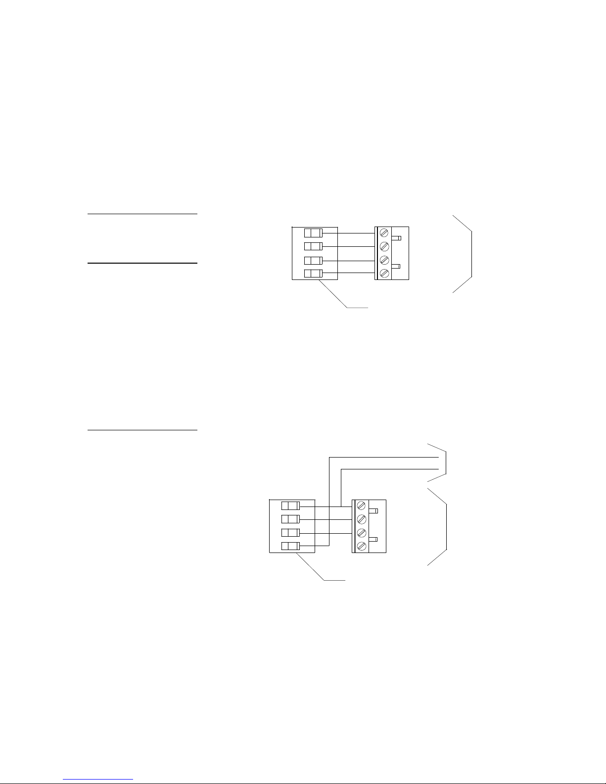
Figure 16
AXlink wiring diagram
Caution
If you are using power from
AXlink, disconnect the wiring
from the control system before
wiring the mini-touch panel.
Using the UniMount and rack-mount AXlink connector for data and power
Connect the control system’s AXlink connector to the AXlink connector (male) on
the rear panel of the mini-touch panel for data and 12 VDC power as shown in
Figure 16.
GND - (BLK)
AXP (WHT)
PWR + (RED)
1
2
3
4
1
GND - (BLK)
AXM (GRN)
2
3
PWR + (RED)
4
UniMount or rack-mount AXlink
connector
Control system
Using the UniMount and rack-mount AXlink connector for data and an
external 12 VDC power supply
Connect the control system’s AXlink connector to the AXlink connector on the rear
panel of the mini-touch panel as shown in Figure 17.
Figure 17
AXlink and external 12 VDC
power supply, and control
system wiring diagram
12 VDC power supply
1
GND - (BLK)
AXP (WHT)
PWR + (RED)
1
2
3
4
UniMount or rack-mount AXlink
connector
GND - (BLK)
AXM (GRN)
2
3
PWR + (RED)
4
Control system
Use an external 12 VDC power supply when the distance between the control system
and mini-touch panel exceeds the limits described in Figure 13. Make sure to connect
only the GND wire on the AXlink connector when using an external 12 VDC power
supply. Do not connect the PWR wire to the AXlink connector’s PWR (+) terminal.
Color Active-Matrix LCD Mini-Touch Panels Installing Mini-Touch Panels 15
Page 24
Using the UniMount and rack-mount 4-pin header for mouse control
Pin 4
Pin 1
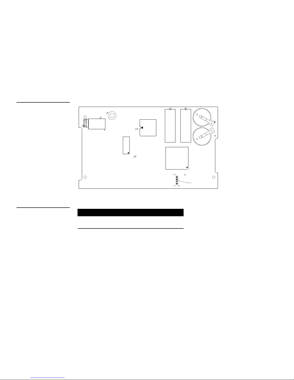
Figure 18 shows the location of the 4-pin header on the UniMount and rack-mount
mini-touch panels. The 4-pin header supports Microsoft and Logitech serial mouse
control devices. Figure 19 lists the 4-pin header and DB-9 connector (male) pinouts.
Figure 18
4-pin header location on the
UniMount and rack-mount minitouch panel circuit card
Figure 19
4-pin header and DB-9
connector pinouts
Connector side of circuit card
4-pin header and DB-9 connector pinouts
4-pin
header Signal Function
1 PWR +12 VDC power 4 and 7 (strap)
2 TXD Transmit data 3
DB-9 connector
(male) pins
4-pin
header
3 RXD Receive data 2
4 GND Ground 5
16 Installing Mini-Touch Panels Color Active-Matrix LCD Mini-Touch Panels
Page 25

Cleaning the Touch Overlay
After installing the mini-touch panel, you should clean the touch overlay. Clean the
touch overlay:
1. Disconnect the AXlink and optional video connectors from the mini-touch
panel.
2. Using a cotton cloth, spray a small amount of cleaning solution consisting of 50-
percent isopropyl alcohol and 50-percent water onto the cloth.
3. Clean the touch overlay with the damp cloth. Then, wipe the touch overlay with
a dry cloth.
4. Reconnect the AXlink and optional video connectors to the mini-touch panel.
Color Active-Matrix LCD Mini-Touch Panels Installing Mini-Touch Panels 17
Page 26

18 Installing Mini-Touch Panels Color Active-Matrix LCD Mini-Touch Panels
Page 27
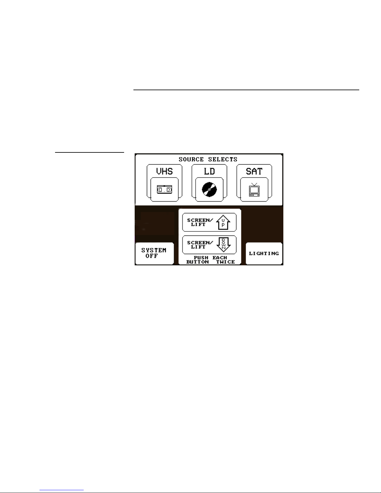
Figure 20
Mini-touch panel page sample
Mini-Touch Panel Basics
Overview
This section contains descriptions and illustration examples of mini-touch panel
pages (Figure 20), buttons, message bars, keypads, and keyboards.
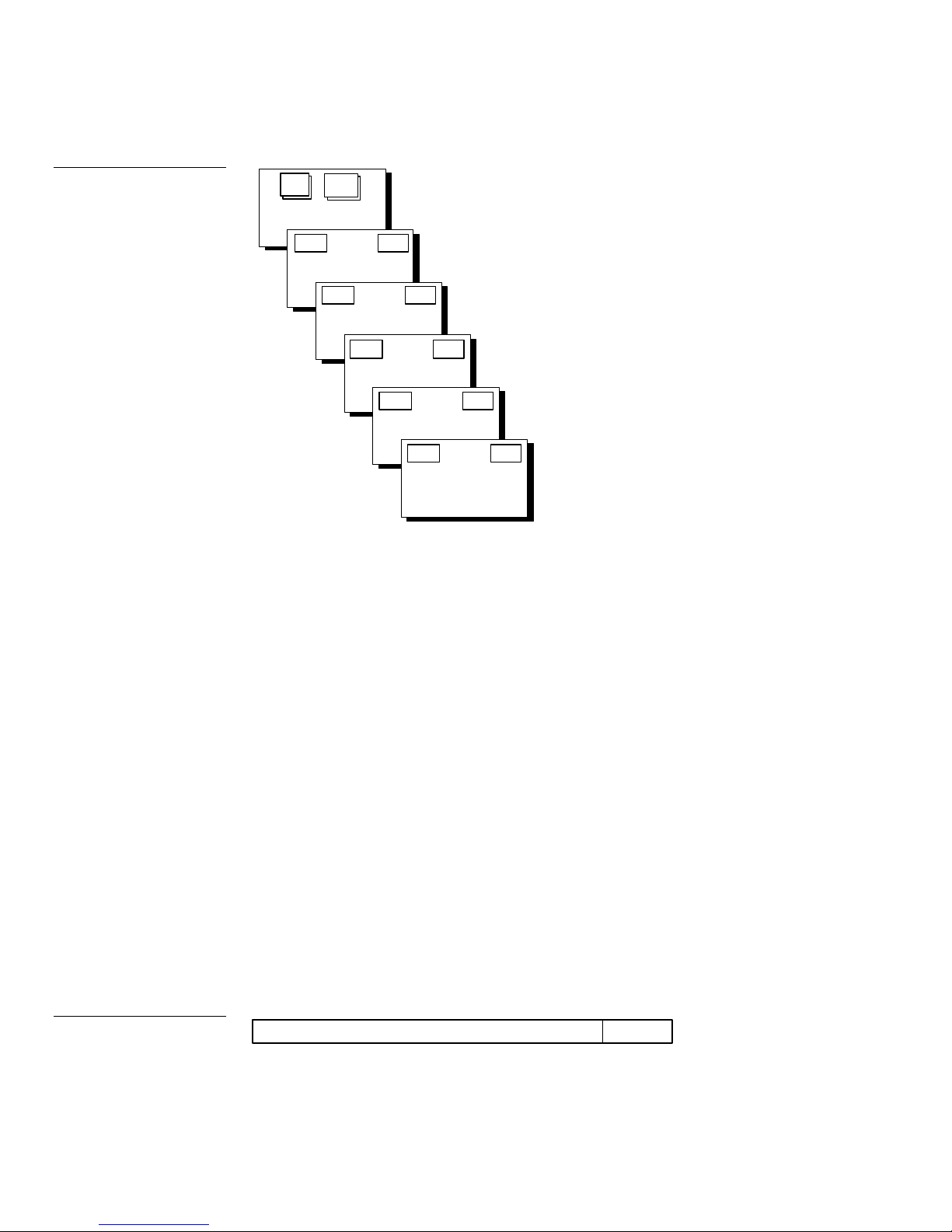
Mini-Touch Panel Pages
You can add objects like buttons, bargraphs, sliders, and drawings to a mini-touch
panel page, and then designate the control functions for each object. The number of
objects depends on the type and quantity of external devices you want to control
with the mini-touch panel and AXCESS Control System. When you create multiple
pages, you must link them with buttons. Figure 21 shows how to link five minitouch panel pages to the Main page. Note that each page contains one button that
goes to the next page, and one that goes to the previous page.
Color Active-Matrix LCD Mini-Touch Panels Mini-Touch Panel Basics 19
Page 28
Setup
Figure 21
Mini-touch panel pages with
linked buttons
Main
Page
Main Page
Page 2 Main
Page 1
Page 3 Page 1
Page 2
Page 4 Page 2
Page 3
Page 5 Page 3
Page 4
Main Page 4
Page 5
Standard Buttons
Standard buttons are rectangles, rectangle variations, and other geometric shapes
that you can create with the mini-touch panel. You can add, revise, and delete
buttons on a mini-touch panel page using the editor bar. B uttons are set with active
attributes, which means there is a response (control system feedback) when you
touch the button.
General Buttons
General buttons are part of the mini-touch panel software program and cannot be
changed. You use general buttons to specify panel communication parameters and
create or revise pages. Some button examples include the message bar, editor bar,
selection, adjustment, keypad, page menu, decision, status, and keyboard.
Message bar
The message bar (Figure 22) appears when you press the editor bar or a menu option
for setup or installation operations. The message bar instructs you to perform an
operation. Press EXIT to return to the Editor Bar. The message portion is not active
(no feedback).
Figure 22
Message bar example
20 Mini-Touch Panel Basics Color Active-Matrix LCD Mini-Touch Panels
TOUCH BUTTON TO CHANGE ATTRIBUTES EXIT
Page 29

Editor bar
PAGE
The editor bar (Figure 23) is a variation of the message bar. It appears whenever the
editor mode is active in the mini-touch panel. Each one of the editor bar menu
options is active. If you press a menu option, a drop-down menu appears.
Figure 23
Editor bar and menu options
Editor bar
BUTTON PAGE
MAIN
ICONS
VERTICAL GRAPH
ICON FEEDBACK
SYSTEM
TIME
DATE
E TIMER
16 CHAR TERM
32 CHAR TERM
JOY STICK
DRAWINGS
BRIGHTNESS
VIDEO SETUP
EXIT
Selection button
Selection buttons (Figure 24) appear throughout the mini-touch panel software
program to open pages, activate YES/NO prompt messages, or set communication
parameters.
Figure 24
Selection button example
Color Active-Matrix LCD Mini-Touch Panels Mini-Touch Panel Basics 21
PROTECTED
SETUP
Information button
Information buttons contain serial numbers and firmware version information.
Figure 25 shows the serial number information button in the Setup Page.
Page 30
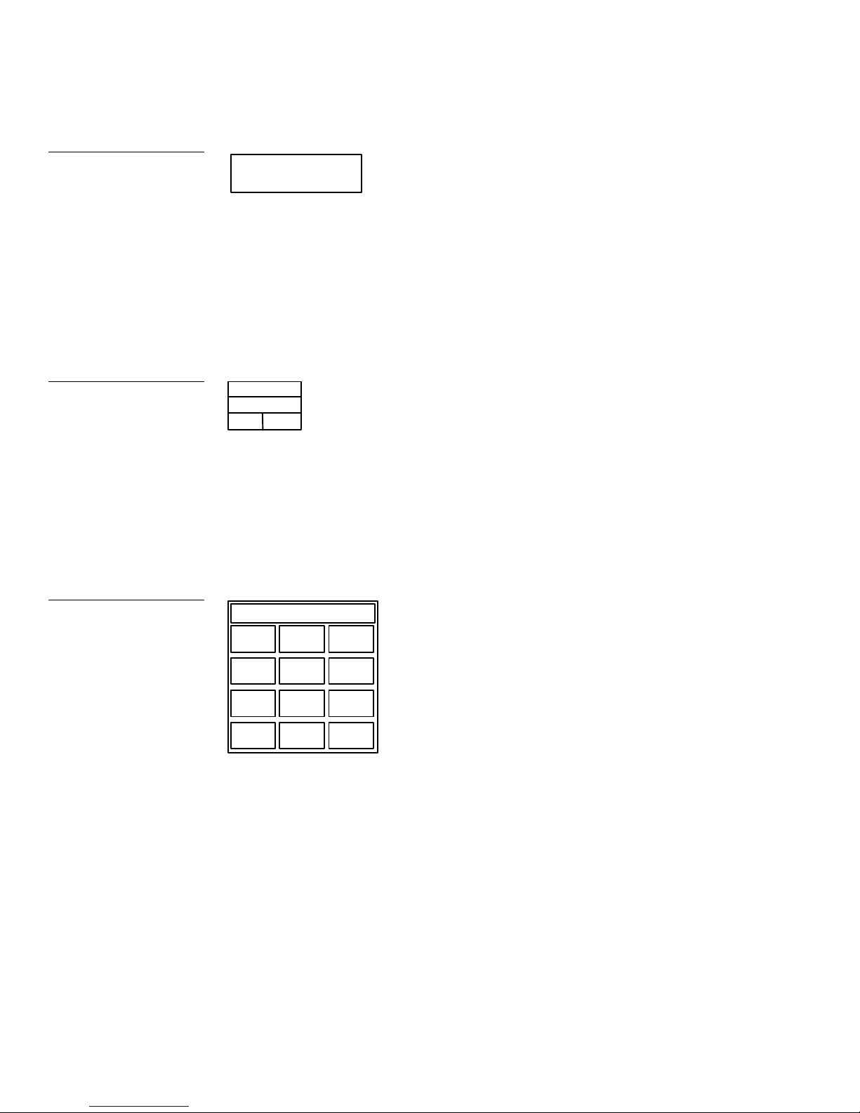
Figure 25
Information button example
SERIAL NO.
924-00-0000
Adjustment button
You can use the UP and DN buttons to set an adjustment button. The adjustment
button example in Figure 26 sets the RS-232 baud rate for serial mouse control
(UniMount and rack-mount models only).
Figure 26
Adjustment button example
Figure 27
Keypad example
BAUD
19.2
UP DN
Button title
Variable data
Keypad buttons
The keypad button opens a keypad (Figure 27) so you can enter a password or value
assignment. All keypad buttons are active except for the entry display.
Entry display
0
0
1 2 3
SET TIME SET
4 5
Keypad entry (0 - 9)
6
7 8 9
CLEAR ENTER
0
CLEAR – Resets entry to 0
ENTER – Processes entry if correct
22 Mini-Touch Panel Basics Color Active-Matrix LCD Mini-Touch Panels
Page 31

Page menu buttons
The page menu button (Figure 28) appears when you need to go to a page, designate
a startup page, or assign a page attribute to a button.
Figure 28
Go to page menu button
example
* * NONE * *
* * PREVIOUS *
NEW PAGE
MAIN PAGE
ENTER
*
List of pages
Up and down buttons
ENTER – Accepts entry
The up, down, and ENTER buttons are active. Use the up and down buttons to scroll
through the list of page names. The highlight bar marks the page name as you scroll
through the list. Press the ENTER button to designate the Go To page or Startup
page.
Decision buttons
Decision buttons ( Figure 29) appear when an operation has two options.
Figure 29
Decision button example
Color Active-Matrix LCD Mini-Touch Panels Mini-Touch Panel Basics 23
YESNO"Decision Text Goes Here"
Decision buttons appear when y ou exit the editor bar, send or receive a drawing,
designate a communication protocol, or make an operation error.
Page 32

Status buttons
LOCK
–
SAVE
LOCK
SAVE
Status buttons (Figure 30) appear when you try to perform operations that do not
function correctly.
Figure 30
Status button example
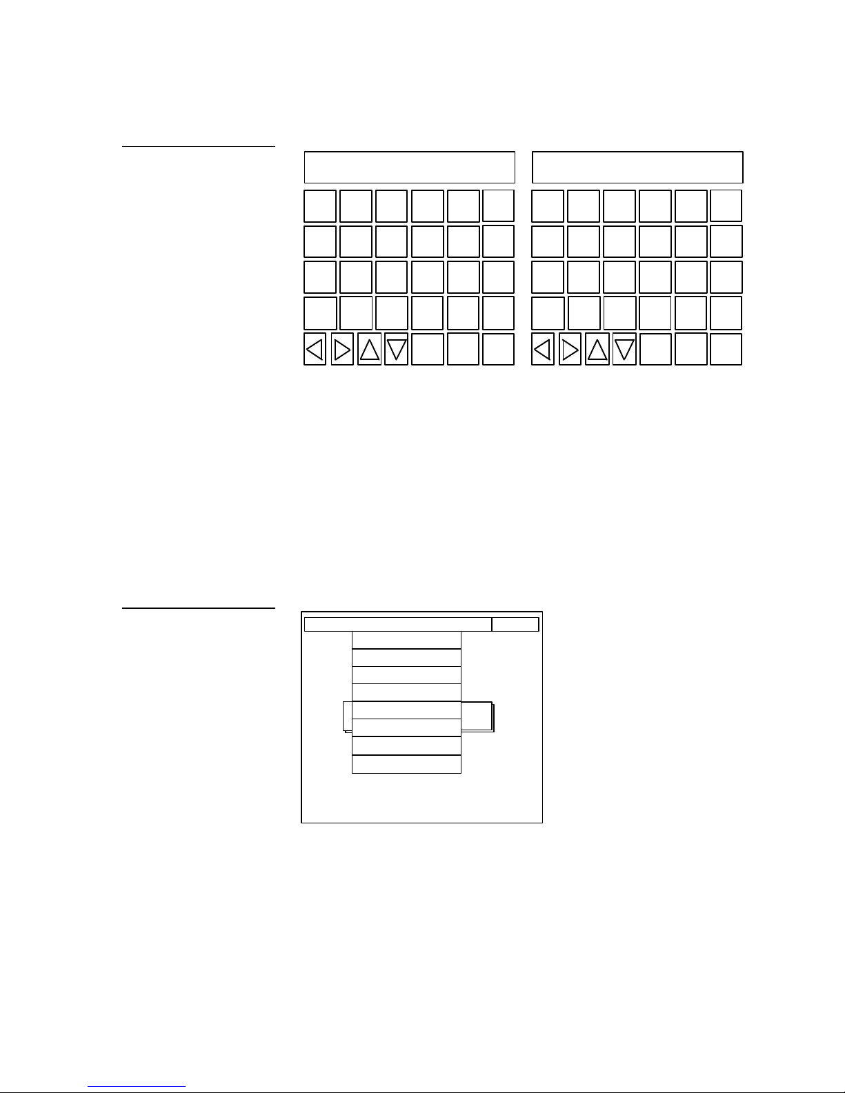
Figure 31
Keyboard page 1 and 2
example
NO COMMUNICATION
TOUCH SCREEN TO CONTINUE
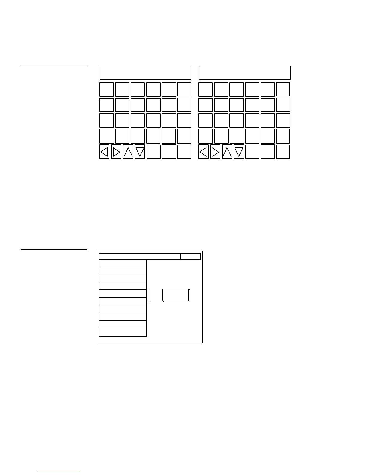
Keyboards
Keyboards (Figure 31) appear so you can type text strings.
Q W E R T
A S D F G
Z X C V
CAP
INTNL
CHARS
SHIFT
SPACE ALT
FONT ABORT
BACK
SPACE
ENTER
DEL
MORE
KEYS
EXIT
Y U I O P
H J K L
N M
B
CAP
INTNL
SPACE ALT
CHARS
:
< >
SHIFT
FONT ABORT
BACK
SPACE
ENTER
DEL
MORE
KEYS
EXIT
Press the MORE KEYS button to toggle between keyboard pages 1 and 2. You use
the keyboard pages during initial setup if you change the time-out message or
power up message. The keyboard pages also appear when you add new pages, type
text output strings, and select the editor bar.
24 Mini-Touch Panel Basics Color Active-Matrix LCD Mini-Touch Panels
Page 1 Page 2
Page 33

Keyboard features and functions include:
• BACK SPACE Moves the cursor back one space to the left.
• ENTER Adds a return to the current line and then moves the cursor to the
next line.
• DEL Deletes the character above the cursor.
• MORE KEYS Toggles between keyboard pages 1 and 2 and the alternate
keyboard pages 1 and 2.
• CAP LOCK Locks all text characters in uppercase. The default mode is CAP
LOCK on.
• INTNL CHARS Changes the keyboard to two additional pages of
international characters for the character set (font) in use.
• SPACE Inserts a space character in your line of text .
• SHIFT Shifts text characters between upper case and lowercase.
• ALT Changes the keyboard to alternate keyboard pages 1 and 2 that contain
additional numbers and punctuation characters .
• Direction arrows Moves the cursor left, right, up, and down within a line or
page of text.
• FONT Opens the font page (Figure 32), which contains five standard fonts,
four outline fonts, and two symbol buttons . You can use the FIXED SYMBOLS
and VARIABLE SYMBOLS for buttons, sliders, and bargraphs.
Color Active-Matrix LCD Mini-Touch Panels Mini-Touch Panel Basics 25
Page 34

Aa
Aa
Aa
AaBbCc
Aa
AaAa
Figure 32
Font page example
Figure 33
Fixed Symbol page 1
AaBb
FIXED
SYMBOLS
VARIABLE
SYMBOLS
Aa Aa
FIXED SYMBOLS Opens the Fixed Symbol pages that contain 22
control symbols. Figure 33 shows the first page of fixed symbols.
26 Mini-Touch Panel Basics Color Active-Matrix LCD Mini-Touch Panels
Page 35

Figure 34
Sample variable symbols
page
VARIABLE SYMBOLS Opens the Variable Symbols pages that can
store up to 223 symbols. Figure 34 is a variable symbol page sample.
Refer to the TPDOC or TPDesign instruction manuals to download
symbols into mini-touch panel memory.
• ABORT Closes the keyboard page without making any text or graphic
character changes.
• EXIT SAVE Closes the keyboard page and stores the text or graphic
changes to memory.
Color Active-Matrix LCD Mini-Touch Panels Mini-Touch Panel Basics 27
Page 36

28 Mini-Touch Panel Basics Color Active-Matrix LCD Mini-Touch Panels
Page 37

Figure 35
Main page
Designing a Mini-Touch Panel Page
Overview
This section contains step-by-step instructions to create a mini-touch panel page and
a button, joy stick, bargraph, and also to set the video display. Once you understand
the basic operations, go through the Mini-Touch Panel Program Reference section to
learn about all the operations you can use to design mini-touch panel pages.
Activate the Editor Bar
Before you can design a mini-touch panel page, you need to activate the editor bar.
When you power up the panel, the first page you should see is the Main page
(Figure 35). If you have a pre-programmed panel, you may not see the Main page.
Refer to the Editor bar and Go to information in the Mini-Touch Panel Program
Reference section to access the Main page.
MAIN
PAGE
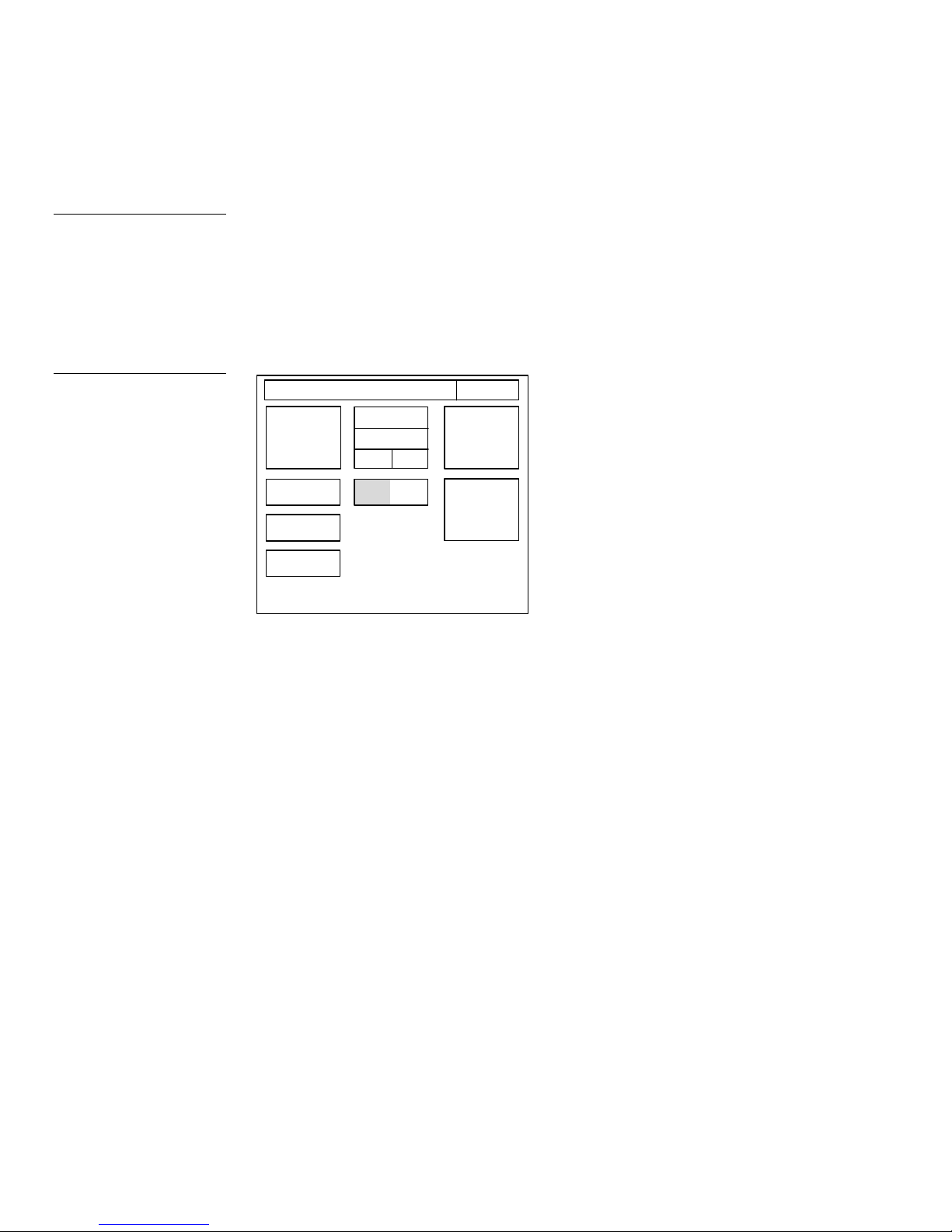
1. Press SETUP in the Main page to open the Setup page ( Figure 36).
SETUP
Color Active-Matrix LCD Mini-Touch Panels Designing a Mini-Touch Panel Page 29
Page 38

1
UP
DN
UP
DN
1
UP
DN
Figure 36
Setup page
ADJUST ATTRIBUTES
BEEP
SET TIME
AND DATE
EXIT
PROTECTED
SETUP
Figure 37
Setup page and password
keypad
LCD TIMER
5 min
SERIAL NO.
924-00-0000
DOUBLE
BEEP
AXlink
vX.XX
SET
BACKGROUND
BRIGHTNESS
2. Press PROTECTED SETUP to open the password keypad shown in Figure 37.
ADJUST ATTRIBUTES EXIT
BEEP
LCD TIMER
5 min
UP DN
SERIAL NO.
924-00-0000
SET TIME
SET TIME
AND DATE
AND DATE
1 2 3
4 5
DOUBLE
DOUBLE
BEEP
BEEP
7 8 9
AXlink
CLEAR ENTER
0
AXlink
vX.XX
PROTECTED
1988
6
BACKGROUND
BRIGHTNESS
SETUP
SET
3. Type 1988, and press ENTER to open the Protected Setup page ( Figure 38). If
you enter a wrong number, press CLEAR and re-enter the number. Refer to the
Set Password subsection to change a password.
30 Designing a Mini-Touch Panel Page Color Active-Matrix LCD Mini-Touch Panels
Page 39

DN
Figure 38
Protected Setup page
ADJUST ATTRIBUTES
EDITOR CALIBRATE
SET
DEVICE
128
EXIT
Figure 39
Main page and editor bar
SETUP
PASSWORD
AUTO
ASSIGN
SET
SERIAL
PAGE
PASSWORD
POWER UP
PAGE
PAGE
TRACKING
LCD TIMER
MESSAGE
TIMER BRT
4
UP
4. Press EDITOR (Figure 39) and EXIT to close the Protected Setup page and return
to the Main page. The editor bar appears at the top of the Main page (Figure 36).
BUTTON PAGE ICONS SYSTEM EXIT
MAIN
PAGE
SETUP
Editor Bar
Color Active-Matrix LCD Mini-Touch Panels Designing a Mini-Touch Panel Page 31
Create a Page
You create mini-touch panel pages using the Page menu option in the editor bar.
Add a page
1. Press PAGE on the editor bar to open the menu options shown in Figure 40.
Page 40

LOCK
–
ENTER
SAVE
Figure 40
Page menu options
Note
The message bar shows the
name of the current page.
PAGE: MAIN PAGE
MAIN
PAGE
PASSWD PG FLIP
PAGE COLOR
ADD
COPY
RENAME
DELETE
GO TO
PRINT
SETUP
EXIT
2. Press the ADD option to add a new page, and then the add page message to
open keyboard page 1 (Figure 41).
Figure 41
Add page message and
keyboard page 1
YOU MUST GIVE THE NEW PAGE A
UNIQUE NAME UP TO 20 LETTERS
TOUCH SCREEN TO CONTINUE
Q W E R T
BACK
SPACE
A S D F G
Z X C V
CAP
INTNL
CHARS
3. Type New Page (Figure 42) using keyboard pages 1 and 2. Press the MORE
KEYS button to toggle between the keyboard pages. The page name can be up to
20 letters.
SHIFTSPACE ALT
FONT ABORT
DEL
MORE
KEYS
EXIT
32 Designing a Mini-Touch Panel Page Color Active-Matrix LCD Mini-Touch Panels
Page 41
LOCK
–
SAVE
LOCK
SAVE
Page 1
Page 2
Figure 42
Add page message and
keyboard pages 1 and 2
NEW PAGE
Q W E R T
BACK
SPACE
NEW PAGE
Y U I O P
BACK
SPACE
Figure 43
Page menu options
A S D F G
Z X C V
CAP
INTNL
CHARS
SHIFT
SPACE ALT
FONT ABORT
ENTER
DEL
MORE
KEYS
EXIT
H J K L
N M
B
CAP
INTNL
CHARS
SHIFT
SPACE ALT
FONT ABORT
< >
ENTER
:
DEL
MORE
KEYS
EXIT
4. Press EXIT SAVE to add NEW PAGE to panel memory, close the keyboard, and
return to the Main page.
Go to NEW PAGE
1. Press PAGE on the editor bar to open the page menu options shown in Figure
43.
PAGE: MAIN PAGE
MAIN
PAGE
PASSWD PG FLIP
PAGE COLOR
ADD
COPY
RENAME
DELETE
GO TO
PRINT
SETUP
EXIT
Color Active-Matrix LCD Mini-Touch Panels Designing a Mini-Touch Panel Page 33
2. Press the GO TO option to open the page list shown in Figure 44.
Page 42

Figure 44
Page list
* * NONE * *
* * PREVIOUS *
*
NEW PAGE
MAIN PAGE
ENTER
3. Press the up or down arrow to move the highlight bar to NEW PAGE.
4. Press ENTER to go to NEW PAGE.
Create a Button
You should be on NEW PAGE, and the editor bar should be visible before you create
a button. If not, start at the beginning of this section.
Add a button
1. Press BUTTON on the editor bar to open the button menu options shown in
Figure 45.
Figure 45
Button menu options
PAGE: NEW PAGE
ADD
MOVE
COPY IMAGE
DELETE
RESIZE
EDIT TEXT
ATTRIBUTES
SAVE
PASTE
SET TO DEFAULT
EXIT
2. Press ADD to add a button to NEW PAGE. The message bar shown in Figure 46
instructs you how to add a button. The first touch point is the upper-left corner
of the button.
34 Designing a Mini-Touch Panel Page Color Active-Matrix LCD Mini-Touch Panels
Page 43

Figure 46
Add a button message bar
Figure 47
Add a button example
TOUCH AND DRAG FOR SIZE
EXIT
3. Drag your finger horizontally across the screen and down to set the height and
width of the button as shown in Figure 47.
Width
Figure 48
Button menu options
Touch point
Height
4. Press EXIT in the message bar to exit add mode.
Resize the button
1. Press BUTTON on the editor bar again to open the menu options shown in
Figure 48.
PAGE: NEW PAGE
ADD
MOVE
COPY IMAGE
DELETE
RESIZE
EDIT TEXT
ATTRIBUTES
SAVE
PASTE
SET TO DEFAULT
Button
EXIT
Color Active-Matrix LCD Mini-Touch Panels Designing a Mini-Touch Panel Page 35
2. Press the RESIZE option to resize the button when the message bar appears.
3. Touch the button and drag your finger horizontally across the screen and down
to resize the button as shown in Figure 49.
Page 44
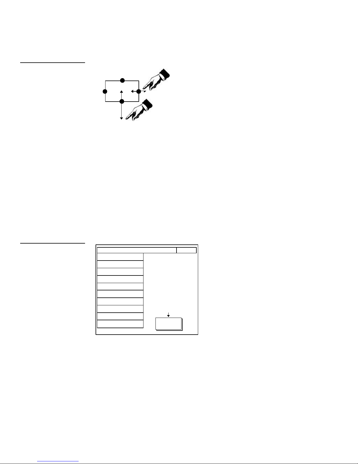
Figure 49
Sizing a button
Touch any edge and
drag to resize.
4. Press EXIT in the message bar to exit resize mode.
Button Attributes
You can use the ATTRIBUTES option on the editor bar to set button borders, page
flips, and assign channel and level codes.
Set the button attributes
1. Press BUTTON on the editor bar to open the button menu options shown in
Figure 50.
Figure 50
Button menu options
V
PAGE: NEW PAGE
ADD
MOVE
COPY IMAGE
DELETE
RESIZE
EDIT TEXT
ATTRIBUTES
SAVE
PASTE
SET TO DEFAULT
Button
EXIT
2. Press ATTRIBUTES and the button you added to open the Attributes page
shown in Figure 51.
36 Designing a Mini-Touch Panel Page Color Active-Matrix LCD Mini-Touch Panels
Page 45

RAISED
Figure 51
Attributes page
BORDER
PAGE: NONE
STRING: NONE
FEEDBACK: CHANNEL
CHANNEL
CODE
NONE
VARIABLE
TEXT
NONE
BRING
BUTTON
TO FRONT
Figure 52
Border options page
Note
The three-dimensional border
option is available in mini-touch
panels equipped with firmware
version 2.0 or higher.
EXIT
EXIT
NO CHANGE
SET
COLORS
Set the border
1. Press BORDER to open the Border options page ( Figure 52).
NO
BORDER
DOUBLE
RAISED
SINGLE
DIAMOND
TRIPLE
SINGLE
WIDE
SINGLE
ROUNDED
DOUBLE
DIAMOND
SHADOWNOBORDER
DOUBLE
WIDE
DOUBLE
ROUNDED
TRIPLE
WIDE
SPECIAL
SINGLE
RAISED
DOUBLE
2
SINGLE
DOUBLE
3
SINGLE
THREE
DIMENSION
Color Active-Matrix LCD Mini-Touch Panels Designing a Mini-Touch Panel Page 37
2. Press SHADOW to reset the button border to shadow style.
Page 46

Set the channel code
1. Press CHANNEL CODE in the Attributes page to open the channel code
keypad.
Note
The channel code for nonactive buttons is 0, and 1–255
for active buttons.
Figure 53
Page list
2. Type 255 in the keyboard. The AXCESS software program uses the channel
code number to identify the button and its operations.
3. Press ENTER to store the channel code in memory, close the keypad, and return
to the Attributes page.
Set the page flip
1. Press PAGE in the Attributes page to open the page list ( Figure 53).
* * NONE * *
* * PREVIOUS *
NEW PAGE
MAIN PAGE
ENTER
2. Press the up or down arrow to move the highlight bar to MAIN PAGE.
*
3. Press ENTER to set the page flip to the MAIN PAGE.
4. Press EXIT in the Attributes page to store the new button attributes in memory
and return to the current page.
5. Press EXIT in the editor bar to exit the attribute's mode.
38 Designing a Mini-Touch Panel Page Color Active-Matrix LCD Mini-Touch Panels
Page 47

Add Text
LOCK
–
SAVE
LOCK
SAVE
You can add text to buttons, joy sticks, and bargraphs using the BUTTON option.
Add text to a button
1. Press BUTTON on the editor bar to open the button menu options list shown in
Figure 54.
Figure 54
Button menu options
Figure 55
Edit text keyboard pages 1 and
2
V
PAGE: NEW PAGE
ADD
MOVE
COPY IMAGE
DELETE
RESIZE
EDIT TEXT
ATTRIBUTES
SAVE
PASTE
SET TO DEFAULT
Button
EXIT
2. Press EDIT TEXT to add text in the button.
3. Touch the button to open the keyboard pages 1 or 2 shown in Figure 55. Press
the MORE KEYS button to toggle between the keyboard pages.
Q W E R T
BACK
SPACE
Y U I O P
BACK
SPACE
Color Active-Matrix LCD Mini-Touch Panels Designing a Mini-Touch Panel Page 39
A S D F G
Z X C V
CAP
INTNL
CHARS
SHIFT
SPACE ALT
FONT ABORT
Page 1 Page 2
ENTER
DEL
MORE
KEYS
EXIT
H J K L
N M
B
CAP
INTNL
CHARS
SHIFT
SPACE ALT
FONT ABORT
< >
ENTER
:
DEL
MORE
KEYS
EXIT
Page 48

Figure 56
Joy stick
4. Type MAIN PAGE. Press MORE KEYS to toggle between keyboard pages 1 and
2. The text appears in the message box at the top of the keyboard as shown in
Figure 55. The mini-touch panel displays an error message if you exceed the
maximum character spaces in the button. Change the size of the button or
reduce the text string to clear the error message.
5. Press EXIT SAVE to close the keyboard and return to the current page.
6. Press EXIT in the editor bar to exit edit text mode.
Create a Joy Stick
You can create a joy stick ( Figure 56) with the ICONS option in the editor bar.
Joy sticks are vertical and horizontal direction controllers you can use for camera
operations, such as pan and tilt. Before you start, make sure to connect the panel to
your AXCESS Control System. Otherwise, the joy stick may not work properly. Refer
to Mini-Touch Panel Program Reference for more information.
Figure 57
Icons menu options
Add a joy stick on a page
1. Press ICONS on the editor bar to open the icons menu options shown in
Figure 57.
BUTTON PAGE
ICONS
SYSTEM
TIME
DATE
E TIMER
16 CHAR TERM
32 CHAR TERM
VERTICAL GRAPH
ICON FEEDBACK
JOY STICK
DRAWINGS
BRIGHTNESS
VIDEO SETUP
EXIT
40 Designing a Mini-Touch Panel Page Color Active-Matrix LCD Mini-Touch Panels
Page 49

Figure 58
Add a joy stick example
2. Press the JOY STICK option to add a joy stick when the message bar appears.
3. Touch the screen to add the new joy stick to the page. Figure 58 shows the
method to add a joy stick.
Touch point
Set the joy stick attributes
1. Press BUTTON on the editor bar to open the button menu options shown in
Figure 59.
Figure 59
Button menu options
PAGE: NEW PAGE
ADD
MOVE
COPY IMAGE
DELETE
RESIZE
EDIT TEXT
ATTRIBUTES
SAVE
PASTE
SET TO DEFAULT
MAIN PAGE
EXIT
Joy stick
2. Press ATTRIBUTES to set the joy stick attributes when the message bar appears.
3. Touch the joy stick to open the Joy stick Attributes page shown in Figure 60.
Color Active-Matrix LCD Mini-Touch Panels Designing a Mini-Touch Panel Page 41
Page 50
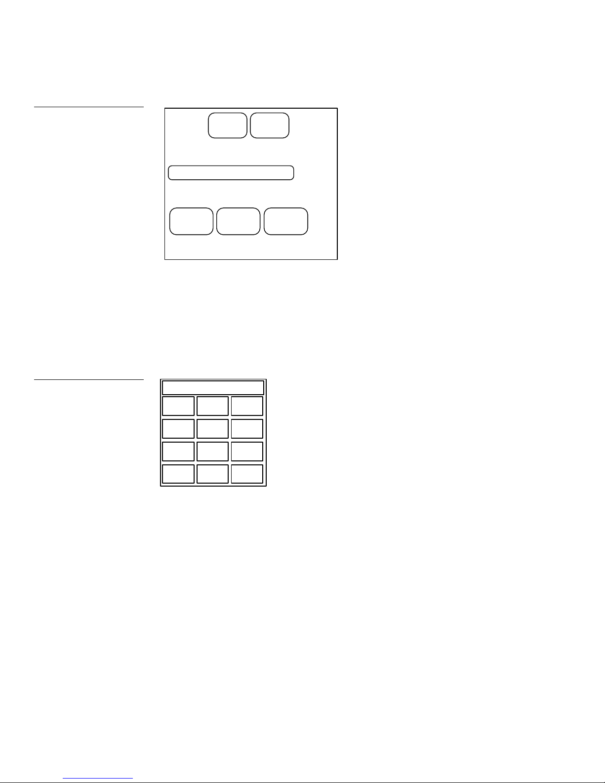
Figure 60
Joy stick Attributes page
CHANNEL
CODE
NONE
FUNCTION: JOYSTICK
LEVEL
CODE
1
Figure 61
Level code keypad
EXIT
EXIT
NO
CHANGE
SET
COLORS
Set the level code
1. Press LEVEL CODE in the Attributes page to open the level code keypad
(Figure 61).
0
1 2 3
4 5
6
7 8 9
CLEAR ENTER
0
2. Type 6 in the keyboard. The AXCESS software program uses level codes 1
through 7 to identify the joy stick and its associated operations. Refer to MiniTouch Panel Program Reference for more information.
3. Press ENTER to store the level code in memory.
4. Press EXIT in the Attributes page to store the new joy stick attributes in memory
and return to the current page.
5. Press EXIT in the editor bar to exit the attribute's mode.
42 Designing a Mini-Touch Panel Page Color Active-Matrix LCD Mini-Touch Panels
Page 51

Figure 62
Bargraph
Create a Bargraph
You can create a bargraph (Figure 62) with the ICONS option in the editor bar.
Bargraphs are level monitors and adjustable level controls you can configure to
monitor and adjust audio outputs and lighting levels. Before you start, make sure to
connect the panel to your AXCESS Control System. Otherwise, the bargraph may not
work properly. Refer to the Mini-Touch Panel Program Reference for more
information.
Add a bargraph to a page
1. Press ICONS on the editor bar to open the icons menu options shown in
Figure 63.
Figure 63
Icons menu options
BUTTON PAGE
ICONS
VERTICAL GRAPH
SYSTEM
TIME
DATE
E TIMER
16 CHAR TERM
32 CHAR TERM
ICON FEEDBACK
JOY STICK
DRAWINGS
BRIGHTNESS
VIDEO SETUP
EXIT
Color Active-Matrix LCD Mini-Touch Panels Designing a Mini-Touch Panel Page 43
Page 52

Figure 64
2. Press the VERTICAL GRAPH option to add a bargraph when the message bar
appears.
3. Touch the screen to add the new bargraph to the page. Figure 64 shows the
method to add a bargraph.
Add and move a bargraph
example
Figure 65
Button menu options
Touch point
Set the bargraph attributes
1. Press BUTTON on the editor bar to open the button menu options shown in
Figure 65.
PAGE: NEW PAGE
ADD
MOVE
COPY IMAGE
DELETE
RESIZE
EDIT TEXT
ATTRIBUTES
SAVE
PASTE
SET TO DEFAULT
Bar graph
MAIN PAGE
EXIT
2. Press ATTRIBUTES to set the bargraph attributes when the message bar
appears.
44 Designing a Mini-Touch Panel Page Color Active-Matrix LCD Mini-Touch Panels
Page 53

3. Touch the bargraph to open the Attributes page shown in Figure 66.
Figure 66
Attributes page for a bargraph
EXIT
LEVEL
CODE
0
BRING
BUTTON
TO FRONT
CHANNEL
CODE
NONE
FEEDBACK: BAR GRAPH
FUNCTION: VERTICAL DISPLAY
EXIT
NO CHANGE
Set the level code
1. Press LEVEL CODE in the Attributes page to open the level code keypad.
2. Type 8 in the keyboard. The AXCESS software program uses level codes 1
through 8 to identify the bargraph and its associated operations. Refer to MiniTouch Panel Program Reference for more information.
3. Press ENTER to store the level code in memory.
4. Press EXIT in the Attributes page to store the new bargraph attributes in
memory and return to the current page.
5. Press EXIT in the editor bar to exit the attribute's mode.
Set the Video Display
After you add a Video Setup button on a page, you can open the Adjust Attributes
page that sets the incoming video signal's brightness, contrast, color, tint, and
compatible video signal. You must connect a live video source to the RCA video
port on the mini-touch panel's rear panel to perform these steps. The Video Setup
button is only available with mini-touch panels equipped with a video port. Go to
Link the New Page to the Main Page instructions if the mini-touch panel is not
equipped with a video port.
1. Press ICONS on the editor bar to open the icons menu shown in Figure 67.
Color Active-Matrix LCD Mini-Touch Panels Designing a Mini-Touch Panel Page 45
Page 54

Figure 67
Icons menu
BUTTON PAGE
ICONS
VERTICAL GRAPH
SYSTEM
TIME
DATE
E TIMER
16 CHAR TERM
32 CHAR TERM
ICON FEEDBACK
JOYSTICK
DRAWINGS
BRIGHTNESS
VIDEO SETUP
EXIT
2. Press VIDEO SETUP and touch the screen to add a Video Setup button.
3. Press the VIDEO SETUP button to open the Video Setup page shown in
Figure 68. The live video appears in the video display area.
Figure 68
Video Setup page
ADJUST ATTRIBUTES EXIT
B
R
I
G
N
T
N
E
S
S
RESET
C
O
N
T
R
A
S
T
Video display area
C
O
L
O
R
NTSC
T
I
N
T
Horizontal sliders
4. Set the brightness, contrast, color, and tint with the horizontal sliders shown in
Figure 68. Set the mini-touch panel for NTSC or PAL composite video with the
button located in the bottom-right corner. The RESET button returns the video
display to factory default settings.
5. Press EXIT in the editor bar to exit the Video Setup page.
46 Designing a Mini-Touch Panel Page Color Active-Matrix LCD Mini-Touch Panels
Page 55

Link the New Page to the Main Page
You use the Attributes page to link buttons to pages.
1. Touch the MAIN PAGE button to flip to the Main page.
2. Press BUTTON on the editor bar to open the button menu options list shown in
Figure 69.
Figure 69
Button menu options
PAGE: NEW PAGE
ADD
MOVE
COPY IMAGE
DELETE
RESIZE
PAGE
EDIT TEXT
ATTRIBUTES
SAVE
PASTE
SET TO DEFAULT
MAIN
SETUP
EXIT
3. Press EDIT TEXT to change the MAIN PAGE button text when the message bar
appears.
4. Touch the MAIN PAGE button to open the keyboard pages 1 and 2 shown in
Figure 65. Press the MORE KEYS button to toggle between the keyboard pages.
5. Press DEL four times to delete MAIN.
6. Type NEW. The revised text appears in the keyboard window as shown in
Figure 70.
Color Active-Matrix LCD Mini-Touch Panels Designing a Mini-Touch Panel Page 47
Page 56
LOCK
–
SAVE
LOCK
SAVE
Figure 70
Keyboard pages 1 and 2
NEW PAGE
Q
W E R T
BACK
SPACE
NEW PAGE
Y
U I O P
BACK
SPACE
Figure 71
Button menu options
A S D F G
Z X C V
CAP
INTNL
CHARS
SHIFT
SPACE ALT
FONT ABORT
ENTER
DEL
MORE
KEYS
EXIT
H J K L
N M
B
CAP
INTNL
CHARS
SHIFT
SPACE ALT
FONT ABORT
< >
ENTER
:
DEL
MORE
KEYS
EXIT
Page 1 Page 2
7. Press EXIT SAVE to close the keyboard.
8. Press EXIT in the message bar to exit edit text mode.
9. Press BUTTON on the editor bar to open the button menu options shown in
Figure 71.
PAGE: NEW PAGE
ADD
MOVE
COPY IMAGE
DELETE
RESIZE
PAGE
EDIT TEXT
ATTRIBUTES
SAVE
PASTE
SET TO DEFAULT
MAIN
SETUP
EXIT
10. Press ATTRIBUTES and the NEW PAGE button to open the Attributes page
shown in Figure 72.
11. Press PAGE in the Attributes page to open the page list.
12. Press the up or down buttons to move the highlight bar to NEW PAGE.
48 Designing a Mini-Touch Panel Page Color Active-Matrix LCD Mini-Touch Panels
Page 57

Figure 72
Attributes page
BORDER
PAGE: MAIN PAGE
STRING: NONE
FEEDBACK: ALWAYS ON
CHANNEL
CODE
NONE
VARIABLE
TEXT
NONE
BRING
BUTTON
TO FRONT
EXIT
EXIT
NO CHANGE
SET
COLORS
13. Press ENTER to set the page flip to the NEW PAGE.
14. Press EXIT in the Attributes page to store the new button attributes in memory
and return to the current page.
15. Press EXIT in the editor bar to exit the attribute's mode.
16. Touch the NEW PAGE and MAIN PAGE buttons to flip between pages.
Close the Editor Bar
After you finish designing the mini-touch panel page, close the editor bar.
Exit editor mode
1. Touch EXIT on the editor bar ( Figure 73).
Figure 73
Main page
Color Active-Matrix LCD Mini-Touch Panels Designing a Mini-Touch Panel Page 49
BUTTON PAGE ICONS SYSTEM EXIT
NEW
PAGE
SETUP
2. Press YES on the exit decision box to close the editor bar.
Page 58

50 Designing a Mini-Touch Panel Page Color Active-Matrix LCD Mini-Touch Panels
Page 59
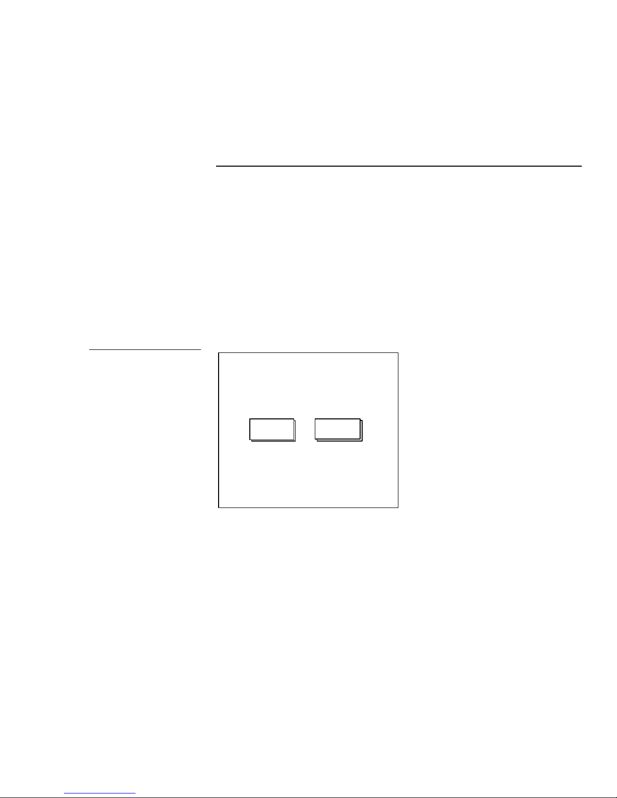
Figure 74
Main page
Mini-Touch Panel Program
Reference
Overview
You can use the Setup page, Protected Setup page, and Editor bar operations to
create mini-touch panel pages. This section describes operations, access flowcharts,
and button options.
Setup Page
You can access the Setup page from the Main page ( Figure 74) that appears when
you power up the mini-touch panel.
MAIN
PAGE
The buttons in the Setup page set the operating parameters of the mini-touch panel.
SETUP
Color Active-Matrix LCD Mini-Touch Panels Mini-Touch Panel Program Reference 51
Page 60

Open the Setup Page
BEEP
1
UP
DN
LCD TIMER
UP
DN
923 -00- 0001
BEEP
1
UP
DN
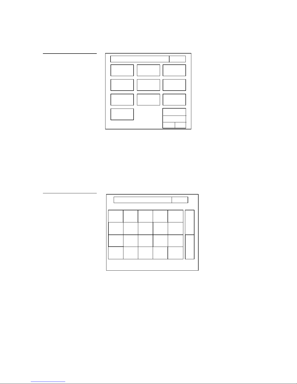
From the Main page, press the SETUP button to open the Setup page shown in
Figure 75.
Figure 75
Setup page
Note
The SmartPack button appears
in the Setup page when a
SMT-PKM Mini-SmartPack is
connected to the TiltScreen
mini-touch panel. The WAVE
button appears in the Setup
page when a WAV-PKM MiniWavePack is connected to the
TiltScreen mini-touch panel.
Figure 76
Setup page flowchart
ADJUST ATTRIBUTES EXIT
15
SERIAL NO.
SmartPack
WAVE
SET TIME
AND DATE
DOUBLE
BEEP
AXlink
vX.XXV
PROTECTED
SETUP
SET
BACKGROUND
BRIGHTNESS
When you select the SETUP button, it changes to a dark background. The flowchart
in Figure 76 shows the buttons you use to access the Setup page.
MAIN
PAGE
SETUP
BUTTON
Buttons
Use the Setup page buttons to configure the mini-touch panel.
Beep
The BEEP button (Figure 77) sets how long the audible beep sounds when you press
the screen.
Figure 77
BEEP button
52 Mini-Touch Panel Program Reference Color Active-Matrix LCD Mini-Touch Panels
Page 61

LCD TIMER
Note
You can override the Beep
value setting using the 'ABEEP'
and 'ADBEEP' System
Send_Commands. Refer to the
AXCESS Programming
subsection for complete
information.
Figure 78
LCD TIMER button
Set the beep value to 0 to disable the beep sound. Press the up and down buttons to
set the beep time in .10-second increments . The minimum beep time setting is 0 and
the maximum is 10 (1 second).
LCD timer
The LCD TIMER button (Figure 78) sets the length of time the mini-touch panel can
be inactive before activating screen-saver mode.
15
UP DN
When the mini-touch panel goes into screen-saver mode, the LCD is powered-down.
With a setting of 5, the panel goes into screen-saver mode if there is no activity for 5
minutes. Press the up and down buttons to change the time that the timer screen
stays on when there is no panel activity. The minimum time setting is 1 and
maximum is 150.
Figure 79
SERIAL NO., AXlink, and
vX.XX button examples
Serial number, AXlink, and vX.XX
The SERIAL NUMBER, AXlink, and vX.XX buttons shown in Figure 79 are nonactive (display only) buttons.
SERIAL NO.
923 -00- 0001
AXlink
vX.XX
The SERIAL NUMBER button shows the serial number AMX assigns to the minitouch panel. The AXlink button is an AXCESS communication indicator that blinks
once every second when the AXCESS Control System is connected to the mini-touch
panel. The vX.XX button shows the current ROM software version installed in the
mini-touch panel.
Color Active-Matrix LCD Mini-Touch Panels Mini-Touch Panel Program Reference 53
Page 62
SmartPack
SLEEP TIME
1
UP
DN
MODULE
BATTERY
SUPPLY
BATTERY
Note
The optional Mini-SmartPack
SMT-PKM can only be used
with a TiltScreen mini-touch
panel.
Figure 80
SmartPack page
The SmartPack button appears on the Setup page when a SMT-PKM MiniSmartPack is connected to the TiltScreen mini-touch panel. The SMT-PKM provides
one-way touch panel control, and transmits RF and high-/low-frequency IR signals.
The SMT-PKM contains a lead-acid rechargeable battery that supplies independent
power to the mini-touch panel. Press the SmartPack button to open the page shown
in Figure 80.
ADJUST SMARTPACK SETTINGS
SMT-PKM
MODULE
VERSION
vX.XX
VOLTAGE
XX.XV
VOLTAGE
XX.XV
CHARGING
EXIT
RF OFF
IR 38kHz
The SmartPack page shows the module type, module version, battery voltage level,
power supply voltage level, battery charge status, and sets the sleep time, RF signal,
and IR signal.
• SMT-PKM MODULE Appears when an optional SMT-PKM is connected to
the mini-touch panel.
• MODULE VERSION vX.XX Shows the ROM firmware version installed in
the SMT-PKM Mini-SmartPack wireless power pack.
• BATTERY VOLTAGE XX.XV Shows the voltage level of the lead-acid
rechargeable battery in the SMT-PKM.
• SUPPLY VOLTAGE XX.XV Shows the voltage level of the external power
supply (optional) connected to the SMT-PKM.
54 Mini-Touch Panel Program Reference Color Active-Matrix LCD Mini-Touch Panels
Page 63

• SLEEP TIME Press the up and down buttons to set the sleep time. The
GROUP ID
1
UP
DN
MODULE
BATTERY
SUPPLY
SLEEP TIME
1
UP
DN
BATTERY
DEVICE
SERVER
DEVICE
NETWORK
RSSIRSSI
SERVER DEVICES
minimum sleep time is 0 (off) and maximum is 150 minutes. When the minitouch panel goes to sleep, all communication stops and battery discharge is
minimized. If the sleep time is set to 5, the panel goes into sleep mode if there
is no activity for 5 minutes. The mini-touch panel will wake up when you
touch the screen.
• BATTERY CHARGING/BATTERY FULLY CHARGED Battery Charging
appears when the lead-acid battery is charging. Battery Fully Charged appears
when the battery is fully charged. The shaded area in the horizontal gauge
moves from left-to-right as the battery voltage level increases.
• RF ON/RF OFF Press to set RF control signals on or off.
• IR 38 kHz/IR 455 kHz/IR OFF Press to set IR control signals to 38 kHz, 455
kHz, or off.
WAVE
Note
The optional WAV-PKM MiniWavePack can only be used
with a TiltScreen mini-touch
panel.
Figure 81
WAVE page
The WAVE button appears on the Setup page when a WAV-PKM Mini-WavePack is
connected to a TiltScreen mini-touch panel. The WAV-PKM provides wireless twoway RF spread-spectrum touch panel control. The WAV-PKM contains a lead-acid
rechargeable battery that supplies independent power to the mini-touch panel. Refer
to the AXR-WAVES Server and Wireless Power Packs instruction manual for more
information. Press the WAVE button to open the page shown in Figure 81.
ADJUST WAVE SETTINGS
WAV-PKM
MODULE
LOCKED ON
VERSION
vX.XX
VOLTAGE
XX.XV
VOLTAGE
XX.XV
CHARGING
EFFICIENCY
XX%
128, 129, 130
EXIT
VERSION
VX.XX
RANGE
XXX-XXX
EFFICIENCY
XX%
Color Active-Matrix LCD Mini-Touch Panels Mini-Touch Panel Program Reference 55
Page 64

The WAVE page shows the module type and communication status, module
version, battery voltage level, power supply voltage level, received signal strength,
battery charge status, device efficiency, server version, device range, network
efficiency, server devices, and sets the group ID number, and sleep time.
• WAV-PKM MODULE Appears when an optional WAV-PKM is connected
to the TiltScreen mini-touch panel. LOCKED ON indicates the mini-touch
panel is locked on to the AXR-WAVES server connected to the control system.
NOT LOCKED indicates the mini-touch panel is not communicating with the
AXR-WAVES server.
• MODULE VERSION vX.XX Shows the ROM firmware version installed in
the WAV-PKM Mini-WavePack wireless power pack.
• BATTERY VOLTAGE XX.XV Shows the voltage level of the lead-acid
rechargeable battery in the WAV-PKM.
• SUPPLY VOLTAGE XX.XV Shows the voltage level of the external power
supply (optional) connected to the WAV-PKM.
• GROUP ID Sets the group ID number on the mini-touch panel to
communicate with the wireless AXR-WAVES Server with the same group ID
number. The group ID range is 0—15. The group ID setting overrides the DIP
switch setting on the WAV-PKM. Refer to the AXR-WAVES Server and Wireless
Power Packs instruction manual to set the group ID number.
• RSSI Shows the strength of the AXR-WAVES Server signal received by the
mini-touch panel. The shaded area in the horizontal gauge moves from left-toright as the RF signal intensity increases. The shaded area should fluctuate
between 50% and 100%.
• BATTERY CHARGING/BATTERY FULLY CHARGED Battery Charging
appears when the lead-acid battery is charging. Battery Fully Charged appears
when the battery is fully charged. The shaded area in the horizontal gauge
moves from left-to-right as the battery voltage level increases.
• DEVICE EFFICIENCY XX% Shows the communication efficiency of bi-
directional RF transmissions between the mini-touch panel and AXR-WAVES
Server. The efficiency percentage (0-100%) is determined by the number of
retries required to complete a panel operation.
56 Mini-Touch Panel Program Reference Color Active-Matrix LCD Mini-Touch Panels
Page 65

• SLEEP TIME Press the up and down buttons to set the sleep time. The
YEAR97UP
DN
UP
DN
HOUR
MONTH
1
UP
DN
UP
DN
MIN
DAY10UP
DN
minimum sleep time is 0 (off) and maximum is 150 minutes. When the minitouch panel goes to sleep, all communication and battery discharge stops. If
the sleep time is set to 5, the panel goes into sleep mode if there is no activity
for 5 minutes. The mini-touch panel will wake up when you touch the screen
for more than .5 seconds.
• SERVER VERSION vX.XX Shows the ROM firmware version installed in
the AXR-WAVES Server that is communicating with the mini-touch panel.
• DEVICE RANGE XXX-XXX Shows the AXlink device numbers that can
communicate with the AXR-WAVES Server. Each AXR-WAVES Server uses a
group ID number and device range to communicate with mini-touch panels
(16 maximum). Refer to the AXR-WAVES Server and Wireless Power Packs
instruction manual for more information about device and group ID settings.
• NETWORK EFFICIENCY XX% Shows the communication status of bi-
directional RF transmissions between all mini-touch panels and AXR-WAVES
Server. The percentage of efficiency (0-100%) is calculated by the number of
retries required to perform a panel operation.
• SERVER DEVICES Shows the AXlink device number of the TiltScreen mini-
touch panels communicating with the AXR-WAVES Server.
Figure 82
Set time and date page
Set time and date
Press the SET TIME AND DATE button to open the page shown in Figure 82.
SET TIME IN 24 HOUR FORMAT
5
5
DISPLAY
MONTH/DAY
EXIT
DISPLAY
12:00
Color Active-Matrix LCD Mini-Touch Panels Mini-Touch Panel Program Reference 57
Page 66

Set the year, month, day, hour, minute, clock display, and day/month display.
• YEAR Press the up and down buttons to set the year.
• MONTH Press the up and down buttons to set the month.
• DAY Press the up and down buttons to set the day.
• HOUR Press the up and down buttons to set the hour.
• MIN Press the up and down buttons to set the minute.
• DISPLAY 12:00/24:00 Press to set the clock display to a 12- or 24-hour
format. For example, the 12-hour clock format changes from 12:00 to 1:00, and
the 24-hour clock changes from 12:00 to 13:00.
• DISPLAY MONTH/DAY, DAY/MONTH Press to set the month and day
display.
Double beep
Press the DOUBLE BEEP button (Figure 83) to enable or disable the double beep
option. The double beep sounds when you press the screen. When the button
background and text is black, the double beep is enabled, and when the background
is white and text is black it is disabled.
Figure 83
DOUBLE BEEP buttons
Note
You can override the Beep
value setting using the 'ABEEP'
and 'ADBEEP' System
Send_Commands. Refer to the
AXCESS Programming
subsection for complete
information.
DOUBLE
BEEP
Enabled
DOUBLE
BEEP
Disabled
Set the BEEP button (described earlier) to 0 to disable the beep sound.
Protected setup
The Protected Setup page (Figure 84) contains various buttons you can use to set up
mini-touch panel pages.
58 Mini-Touch Panel Program Reference Color Active-Matrix LCD Mini-Touch Panels
Page 67
UP
DN
TIMER BRT
TRA
A
T
A
Figure 84
Protected Setup page
ADJUST ATTRIBUTES
EDITOR CALIBRATE
SET
DEVICE
128
EXIT
Figure 85
Set Choose Color page
SETUP
PASSWORD
AUTO
ASSIGN
SET
SERIAL
PAGE
PASSWORD
POWER UP
PAGE
PAGE
TRACKING
LCD TIMER
MESSAGE
5
Because there are so many operations associated with Protected Setup page buttons,
they are all described in the Protected Setup Page subsection.
Set background
Press the SET BACKGROUND button to open the page shown in Figure 85.
CHOOSE COLOR EXIT
DARK
BLACK
DARK
MAGENTA
MEDIUM
CREAM
GRAY
YELLOW BLUE MAGENTA CYAN WHITE
RED
DARK
CYAN
MICROSOFT
MOUSE
DARK
GREEN
LIGHT
GRAY
DARK
GRAY
DARK
YELLOW
MONEY
GREEN
DARK
BLUE
SKY
BLUE
RED GREEN
N
S
P
R
E
N
B
O
R
T
Color Active-Matrix LCD Mini-Touch Panels Mini-Touch Panel Program Reference 59
Then, select the background color for the Setup pages.
• TRANSPARENT Not functional for this operation.
• ABORT Returns to the Setup page.
Page 68
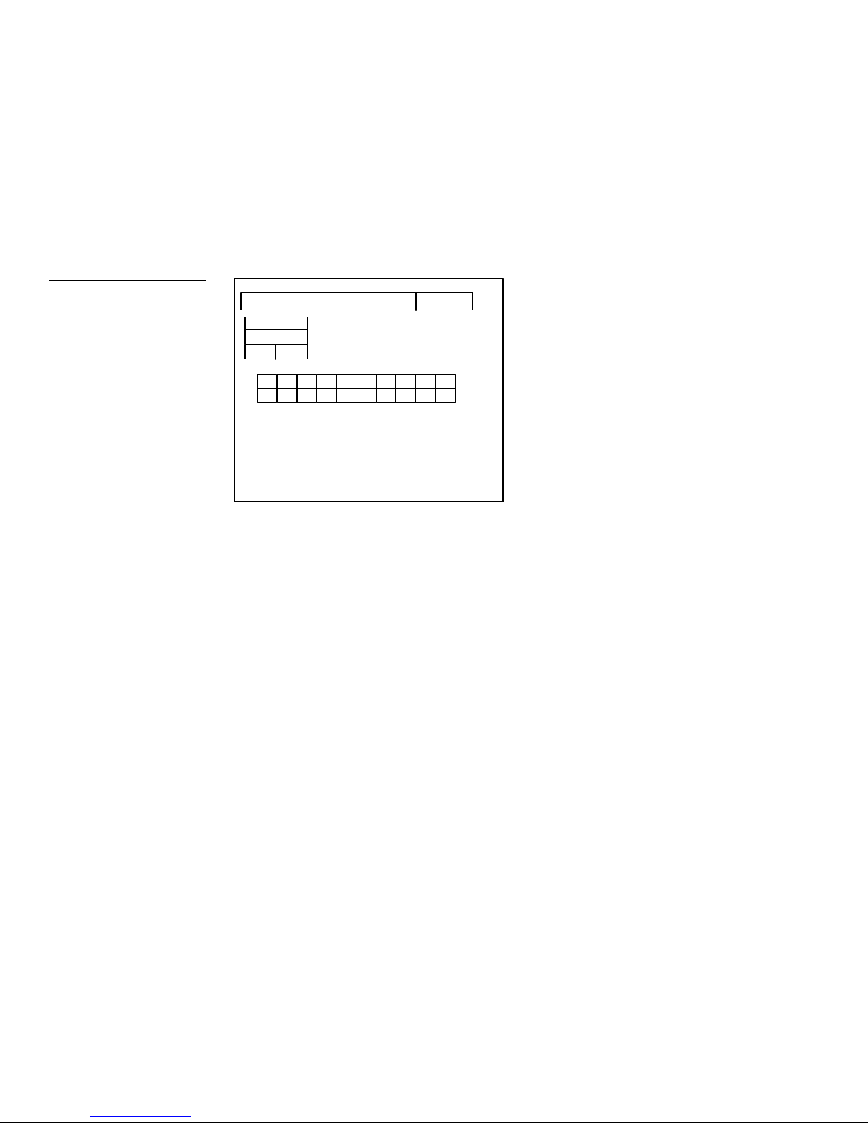
Brightness
UP
DN
Press the BRIGHTNESS button in the Setup page to open the page shown in
Figure 86.
Figure 86
Brightness page
ADJUST ATTRIBUTES EXIT
BRIGHT
8
Set the brightness and contrast levels for the screen.
• BRIGHT Press the up and down buttons to set the screen brightness. The
minimum brightness level is 1 and maximum is 8.
60 Mini-Touch Panel Program Reference Color Active-Matrix LCD Mini-Touch Panels
Page 69

Protected Setup Page
BUTTON
DN
The Protected Setup page allows you to set passwords, mouse controls, and
communications parameters. The flowchart in Figure 87 shows how to access the
Protected Setup page.
Figure 87
Protected setup page flowchart
Figure 88
Protected Setup page
MAIN
PAGE
SETUP
BUTTON
PROTECTED SETUP
TYPE
1988
The Protected Setup page is password-protected; so, when you press the
PROTECTED SETUP button on the Setup page, a number keypad appears. If the
editor bar is active, you do not have to type the password each time you press the
PROTECTED SETUP button.
Open the Protected Setup Page
Type 1988, which is the system default password, and press ENTER to open the
Protected Setup page. (You can change the password, which is explained in the Setup
Password subsection.) If you enter a wrong number, press CLEAR and re-enter the
number. The Protected Setup page (Figure 88) appears when you enter the correct
number.
ADJUST ATTRIBUTES
EDITOR CALIBRATE
SET
DEVICE
128
EXIT
Color Active-Matrix LCD Mini-Touch Panels Mini-Touch Panel Program Reference 61
SETUP
PASSWORD
AUTO
ASSIGN
SET
SERIAL
PAGE
PASSWORD
POWER UP
PAGE
PAGE
TRACKING
LCD TIMER
MESSAGE
TIMER BRT
4
UP
Page 70

Figure 89
EDITOR buttons
Protected Setup Page Buttons
Use the Protected Setup page buttons to set the edit option and system parameters.
Editor
Press the EDITOR button to activate the editor bar. The mini-touch panel is in editor
mode if the EDITOR button background is black with white text, and off when the
button background is white with black text ( Figure 89).
EDITOREDITOR
On Off
When you exit the Protected Setup page, the editor bar appears at the top or bottom
of the screen (Figure 90). You can use the editor bar to create buttons, pages, icons,
and also set system settings. Since there are so many operations associated with the
editor bar, they are described in the Editor Bar subsection.
Figure 90
Editor bar example
BUTTON PAGE ICONS SYSTEM EXIT
MAIN
PAGE
SETUP
Editor bar
62 Mini-Touch Panel Program Reference Color Active-Matrix LCD Mini-Touch Panels
Page 71
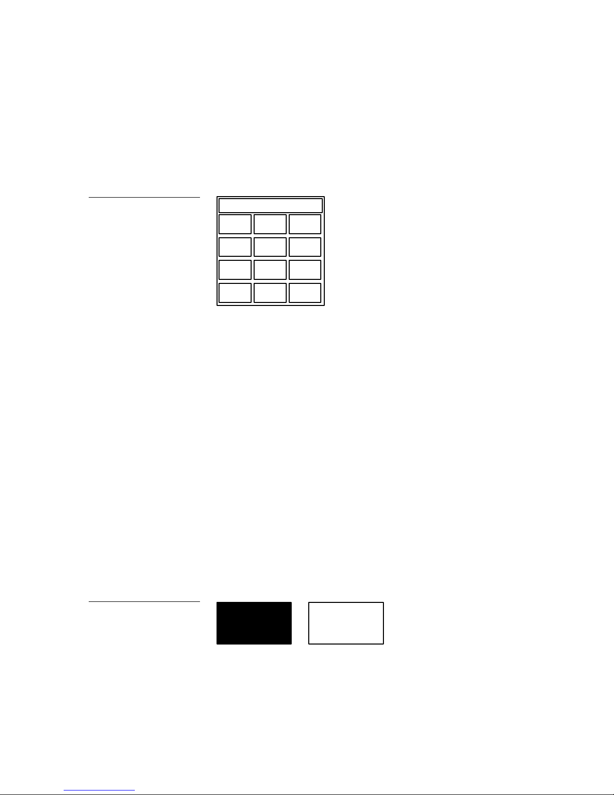
Setup password
Press the SETUP PASSWORD button to open the password keypad ( Figure 91) and
change the Setup page password number.
Figure 91
Password keypad
1988
SET TIME
AND DATE
1
SET TIME SET
4 5
DOUBLE
2 3
SET
6
0
BEEP
7 8 9
AXlink
CLEAR ENTER
v2.xx
0
The password number range is 1 through 9999. (Do not use zero.) Do not change the
Setup page password unless you are concerned about unauthorized access to minitouch pages. If you change the password, write the new number down and keep it in
a secure place.
• CLEAR Clears the keypad number.
• ENTER Sets the password number, closes the keypad, and returns to the
Protected Setup page.
Auto assign
Figure 92
AUTO ASSIGN buttons
Color Active-Matrix LCD Mini-Touch Panels Mini-Touch Panel Program Reference 63
Press the AUTO ASSIGN button to assign channel code numbers for new buttons.
Channel code numbers are used by the mini-touch panel and AXCESS Control
System to keep track of operations you assign to each button. Auto Assign is on
when the button background is black with white text, and off when the button
background is white with black text ( Figure 92).
AUTO
ASSIGN
On Off
AUTO
ASSIGN
Page 72

Set serial
UP
DN
Press the SET SERIAL button to open the Adjust Serial Settings page shown in
Figure 93.
Figure 93
Adjust Serial Settings page
Note
The mouse control option is not
available for TiltScreen minitouch panels.
Note
You can still control the minitouch panel with your finger
when mouse control is active.
ADJUST SERIAL SETTINGS EXIT
SPEED
8
BAUD
38.4
UP DN
MICROSOFT
MOUSE
BOTH
MODE
MOUSE
BORDER
COLOR
MOUSE
ON
POWER UP
MESSAGE
MOUSE
FILL
COLOR
The 4-pin header in the UniMount and rack-mount mini-touch panels are set to 1,200
baud when you activate the MOUSE ON button. The RS-232 communication
automatically defaults to the baud rate set on the Set Serial page if you disable the
MOUSE ON button.
• SPEED Increases or decreases the movement speed of the mouse pointer
with the up and down buttons. Minimum (slow) speed is 1 and the maximum
(fast) is 10.
Note
Make sure to match the baud
transmission rate for the
external mouse.
• BAUD Press the up or down buttons to set the data communication speed
for the mini-touch panel’s RS-232 4-pin header. The baud rates are 300; 600;
1,200; 2,400; 4,800; 9,600; 19,200; and 38,400.
• MICROSOFT MOUSE or LOGITECH MOUSE Sets the mouse control
interface for a Microsoft or Logitech mouse.
• BUS MODE, RS232 MODE, BOTH MODE Sets the data signal output for
the mini-touch panel.
BUS MODE Transmits AXlink data through the 4-pin AXlink connector on
UniMount and rack-mount mini-touch panels.
64 Mini-Touch Panel Program Reference Color Active-Matrix LCD Mini-Touch Panels
Page 73

RS232 MODE Transmits RS-232 data through the 4-pin RS-232 header in the
LOCK
–
SAVE
LOCK
SAVE
UniMount and rack-mount mini-touch panels.
BOTH MODE Transmits AXlink data through the AXlink connector and RS232 data through the 4-pin header in the UniMount and rack-mount minitouch panels.
• MOUSE ON Sets the mini-touch panel for mouse control. Mouse control is
on when the button background is black with white text, and off when the
button background is white with black text.
• POWER UP MESSAGE Press the POWER UP MESSAGE button to open
keyboard pages 1 and 2 shown in Figure 94. The power up message is sent by
the mini-touch panel when power is first applied.
Figure 94
Power up message keyboard
pages 1 and 2
GOOD MORNING
Q W E R T
A S D F G
Z X C V
CAP
INTNL
CHARS
SHIFT
SPACE ALT
FONT ABORT
BACK
SPACE
ENTER
MORE
KEYS
EXIT
GOOD MORNING
Y U I O P
H J K L
DEL
B
CAP
N M
INTNL
CHARS
< >
SHIFT
SPACE ALT
FONT ABORT
:
Page 1 Page 2
BACK SPACE Moves the cursor back one space to the left.
ENTER Adds a return to the current line and then moves the cursor to the
next line.
DEL Deletes the character above the cursor.
BACK
SPACE
ENTER
DEL
MORE
KEYS
EXIT
Color Active-Matrix LCD Mini-Touch Panels Mini-Touch Panel Program Reference 65
MORE KEYS Toggles between keyboard pages 1 and 2.
CAP LOCK Toggles between uppercase and lowercase text characters. The
default mode is CAP LOCK on.
Page 74

INTNL CHARS Changes the keyboard to two additional pages of
international characters for the character set (font) in use.
SPACE Inserts a space character in your line of text .
SHIFT Shifts text characters between upper case and lowercase.
ALT Changes the keyboard to alternate keyboard pages 1 and 2 that contain
additional numbers and punctuation characters .
Direction arrows Moves the cursor left, right, up, and down within a line or
page of text.
FONT Not functional for this operation.
ABORT Closes the keyboard page without making any text or graphic
character changes.
EXIT SAVE Closes the keyboard page and stores the text to memory.
• MOUSE FILL COLOR Press to open the Choose Color page and select a
color for the mouse pointer.
Set device
Figure 95
Device number keypad
Press the SET DEVICE button to open the device number keypad ( Figure 95) and
enter an AXlink device number; the range is 1 through 255.
128
1 2 3
4 5
6
7 8 9
CLEAR ENTER
0
The device number identifies the mini-touch panel within the AXCESS Control
System. Devices connected to the control system must be assigned unique AXlink
device numbers. Do not use duplicate device numbers to avoid communication
problems between the mini-touch panel and control system.
66 Mini-Touch Panel Program Reference Color Active-Matrix LCD Mini-Touch Panels
Page 75

• CLEAR Clears the keypad number.
• ENTER Sets the device number, closes the keypad, and returns to the
Protected Setup page.
Page password
Press the PAGE PASSWORD button to open the password keypad; the range is 1
through 9999.
If you try to open a password-protected page, a keypad appears and you must enter
the correct password to open the new page. Refer to Password Page Flips in the Editor
Bar subsection to set the attributes for password protection.
• CLEAR Clears the keypad number.
• ENTER Sets the page password number, closes the keypad, and returns to
the Protected Setup page.
Power up page
Press the POWER UP PAGE button to open the Power Up page list ( Figure 96).
Figure 96
Power Up page list
* * NONE * *
* * PREVIOUS * *
MAIN PAGE
ENTER
Select a page to designate the first page to open when you power up the mini-touch
panel. Move the highlight bar to a page name, ** NONE **, or ** PREVIOUS ** using
the up and down buttons. Press ENTER to set the Power Up page.
Color Active-Matrix LCD Mini-Touch Panels Mini-Touch Panel Program Reference 67
Page 76

Note
• Up arrow Moves the highlight bar up.
Select ** NONE ** or
** PREVIOUS ** to set the
mini-touch panel to start up
with the last active page.
Figure 97
Calibrate decision box
• Down arrow Moves the highlight bar down.
• ENTER Sets the power up page and returns to the Protected Setup page.
Calibrate
Press the CALIBRATE button to open the decision box ( Figure 97) and reset the
vertical and horizontal touch points on the screen.
YES NO
THIS FUNCTION IS
****FACTORY SET*****
PRESS NO TO EXIT
• YES Starts the calibration test. Carefully press each crosshair using your
finger or a dull pointer. When the calibration is complete, press the screen to
return to the Protected Setup page. Perform the calibration test when the
touch points and buttons are misaligned.
• NO Cancels the calibration test.
Figure 98
PAGE TRACKING buttons
Page tracking
Press the PAGE TRACKING button to set the page tracking option. When the page
tracking button is enabled, the mini-touch panel sends active page data back to the
AXCESS Control System, 4-pin RS-232 header in the UniMount and rack mount
mini-touch panels, or both depending on which option you select in the Adjust
Serial Settings page. The data can be used to control pages in another mini-touch
panel. Page tracking is on when the button background is black with white text
(Figure 98), and off when the background is white with black text.
PAGE
TRACKING
On Off
PAGE
TRACKING
68 Mini-Touch Panel Program Reference Color Active-Matrix LCD Mini-Touch Panels
Page 77

LOCK
–
SAVE
LOCK
SAVE
Figure 99
LCD Timer page
LCD timer message
Press the LCD TIMER MESSAGE button to open the page shown in Figure 99.
TEXT MESSAGE CLOCK DISPLAY
DRAWING VIDEO
The LCD Timer Message appears when the mini-touch panel is in screen-saver
mode.
• TEXT MESSAGE Opens keyboard pages 1 and 2 (Figure 100) so you can
type a screen-saver message.
Figure 100
Keyboard pages 1 and 2
TOUCH SCREEN TO ACTIVATE
Q W E R T
A S D F G
BACK
SPACE
ENTER
Z X C V
CAP
INTNL
SPACE ALT
CHARS
SHIFT
FONT ABORT
MORE
KEYS
EXIT
TOUCH SCREEN TO ACTIVATE
Y U I O P
H J K L
DEL
CAP
B
N M
INTNL
SPACE ALT
CHARS
SHIFT
FONT ABORT
:
< >
Page 1 Page 2
BACK SPACE Moves the cursor back one space to the left.
ENTER Adds a return to the current line and then moves the cursor to the
next line.
DEL Deletes the character above the cursor.
BACK
SPACE
ENTER
DEL
MORE
KEYS
EXIT
Color Active-Matrix LCD Mini-Touch Panels Mini-Touch Panel Program Reference 69
Page 78

MORE KEYS Toggles between keyboard pages 1 and 2.
MEDIUM
CAP LOCK Toggles between uppercase and lowercase text characters. The
default mode is CAP LOCK on.
INTNL CHARS Changes the keyboard to two additional pages of
international characters for the character set (font) in use.
SPACE Inserts a character space in your line of text .
SHIFT Shifts text characters between upper case and lowercase.
ALT Changes the keyboard to alternate keyboard pages 1 and 2 that contain
additional numbers and punctuation characters .
Direction arrows Moves the cursor left, right, up, and down within a line or
page of text.
FONT Not functional for this operation.
ABORT Closes the keyboard page without making any text or graphic
character changes.
EXIT SAVE Closes the keyboard page and stores the text to memory.
Figure 101
Clock Display page
• CLOCK DISPLAY Opens the Clock Display page (Figure 101). Figure 102
shows the clock display sizes.
ADJUST ATTRIBUTES
X-SMALL
X-LARGE
SMALL
LARGE
EXIT
70 Mini-Touch Panel Program Reference Color Active-Matrix LCD Mini-Touch Panels
Page 79

12:31
TIME
12:31
X-Small
X-Large
Figure 102
Clock display sizes
TIME
TIME
12:31
TIME
12:31
Small Large
Medium
TIME
12:31
• DRAWING Opens the drawing page list (Figure 103). Select a drawing to
appear when the mini-touch panel is in screen-saver mode. Refer to System
Menu Options subsection for more information about drawings.
Figure 103
Drawing page list
* * NONE * *
COMPANY LOGO
ENTER
Direction arrows Moves the cursor left, right, up, and down within a line or
page of text.
Up arrow Moves the highlight bar up.
Down arrow Moves the highlight bar down.
ENTER Sets the drawing to appear in screen-saver mode and returns to the
Protected Setup page.
• VIDEO Sets the mini-touch panel to display video when the mini-touch
panel is in screen-saver mode.
Color Active-Matrix LCD Mini-Touch Panels Mini-Touch Panel Program Reference 71
Page 80

Timer BRT
UP
DN
PAGE
BUTTON
Press the TIMER BRT button to set the brightness level for the LCD Timer Message
Options. When the mini-touch panel goes into sleep mode, the TIMER BRT level sets
how bright the message appears. The minimum settings is 0 (off) and the maximum
is 4.
Figure 104
Timer BRT buttons
Figure 105
Editor bar flowchart
TIMER BRT
4
Editor Bar
Press the EDITOR button in the Protected Setup page to activate the editor bar. The
Protected Setup page remains open until you press EXIT. Then, the editor bar
appears on every page. The flowchart in Figure 105 shows the sequence to activate
the editor bar.
MAIN
SETUP
PROTECTED
SETUP
TYPE
1988
EDITOR
EXIT
BUTTON
When you press the EXIT button in the Protected Setup page ( Figure 106), you
return to the Main page (Figure 107) and the editor bar appears at the top of the
page.
Figure 106
ADJUST ATTRIBUTES
EDITOR button in the
Protected Setup page
EDITOR CALIBRATE
SETUP
PASSWORD
AUTO
ASSIGN
SET
SERIAL
72 Mini-Touch Panel Program Reference Color Active-Matrix LCD Mini-Touch Panels
SET
DEVICE
128
PAGE
PASSWORD
POWER UP
PAGE
EXIT
PAGE
TRACKING
LCD TIMER
MESSAGE
Page 81

BUTTON
EXIT
Figure 107
Editor bar example
PAGE ICONS SYSTEM
Editor Bar
Figure 108
Button menu options list
MAIN
PAGE
SETUP
The editor bar options BUTTON, PAGE, ICONS, SYSTEM, and EXIT appear on
every page you open.
Button Menu Options
Press BUTTON to open the Button Menu Options list shown in Figure 108.
PAGE: NEW PAGE
ADD
MOVE
COPY IMAGE
DELETE
RESIZE
EDIT TEXT
ATTRIBUTES
SAVE
PASTE
SET TO DEFAULT
EXIT
Color Active-Matrix LCD Mini-Touch Panels Mini-Touch Panel Program Reference 73
The options include operations to create, configure, and revise buttons. The editor
bar, shown at the top (default) of the screen, shows the page name. Press EXIT to
close the option's list.
Page 82

Add
X=92 Y=140 DRAG BUTTON
X=92 Y=140 DRAG TO COPY
Press the ADD option and add a button when the message bar appears. The first
touch point is the upper-left corner of the button.
Drag your finger horizontally across the screen and down to set the height and
width of the button. Figure 109 shows how to add a new button.
Figure 109
Add a button on a page
Note
You can adjust the button
position with the MOVE and
RESIZE options.
Figure 110
Move message bar
Width
Touch point
Height
Press the EXIT button in the editor bar to exit. You can use the ATTRIBUTES option
to set the border style and configuration settings.
Move
Press the MOVE option to move a button, joy stick, or bargraph when the message
bar (Figure 110) appears. Drag the button to the new position. The X and Y
coordinates show the button position on the screen. Press the EXIT button in the
editor bar to exit.
EXIT
Copy image
Press the COPY IMAGE option to copy a button, joy stick, or bargraph when the
message bar (Figure 111) appears on the screen.
Figure 111
Copy image message bar
Press the target button, joy stick, or bargraph and drag the button copy to the new
position. The X and Y coordinates show the button position on the screen. Press the
EXIT button in the editor bar to exit.
74 Mini-Touch Panel Program Reference Color Active-Matrix LCD Mini-Touch Panels
EXIT
Page 83

Delete
Press the DELETE option to delete a button, joy stick, or bargraph when the message
bar (Figure 112) appears.
Figure 112
Delete message bar
Figure 113
Delete button decision box
TOUCH BUTTON TO DELETE
EXIT
Press the target button, joy stick, or bargraph you want to delete to open the decision
box shown in Figure 113.
ARE YOU SURE
YOU WANT TO
YES
DELETE THIS BUTTON?
NO
• YES Deletes the button, joy stick, or bargraph and returns to the current
page. Press the EXIT button in the editor bar to exit.
• NO Cancels the deletion process and returns to the current page. Press the
EXIT button in the editor bar to exit.
Resize
Press the RESIZE option to resize a button when the message bar ( Figure 114)
appears.
Figure 114
Resize message bar
Color Active-Matrix LCD Mini-Touch Panels Mini-Touch Panel Program Reference 75
TOUCH AND DRAG TO RESIZE
EXIT
Drag your finger horizontally across the screen and down to resize the height and
width as shown in Figure 115.
Page 84
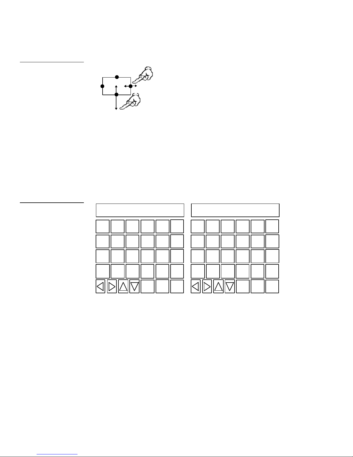
LOCK
–
SAVE
LOCK
SAVE
Figure 115
Resizing a button
Touch any edge and
drag to resize.
Press the EXIT button in the editor bar to exit. If you add text to a button, the button
size must be large enough to accommodate the text string.
Edit text
Press the EDIT TEXT option and a button to open keyboard pages 1 and 2 shown in
Figure 116. With this option you can edit the text that appears on a button. After you
close the keyboard, press the EXIT button in the editor bar to exit.
Figure 116
Edit text keyboard pages 1 and
2
GOOD MORNING
Q W E R T
A S D F G
Z X C V
CAP
INTNL
CHARS
SHIFT
SPACE ALT
FONT ABORT
BACK
SPACE
ENTER
MORE
KEYS
EXIT
GOOD MORNING
Y U I O P
H J K L
DEL
B
CAP
N M
INTNL
SPACE ALT
CHARS
:
< >
SHIFT
FONT ABORT
BACK
SPACE
ENTER
DEL
MORE
KEYS
EXIT
Page 1 Page 2
Type the button text into keyboard pages 1 and 2. You can alternate between the
keyboard pages using the MORE KEYS button. The text appears in the message box
at the top of the keyboard page. The mini-touch panel opens an error message if the
text string exceeds the space in the button. Change the size of the button or reduce
the font size to clear the error message. Special keyboard button descriptions follow.
• BACK SPACE Moves the cursor back one space to the left.
• ENTER Adds a return to the current line and then moves the cursor to the
next line.
76 Mini-Touch Panel Program Reference Color Active-Matrix LCD Mini-Touch Panels
Page 85

• DEL Deletes the character above the cursor.
Aa
Aa
Aa
AaBbCc
Aa
AaAa
• MORE KEYS Toggles between keyboard pages 1 and 2.
• CAP LOCK Toggles between uppercase and lowercase text characters. The
default mode is CAP LOCK on.
• INTNL CHARS Changes the keyboard to two additional pages of
international characters for the character set (font) in use.
• SPACE Inserts a space character in your line of text .
• SHIFT Shifts text characters between upper case and lowercase.
• ALT Changes the keyboard to alternate keyboard pages 1 and 2 that contain
additional numbers and punctuation characters .
• Direction arrows Moves the cursor left, right, up, and down within a line or
page of text.
• FONT Opens the Font page (Figure 117). Select a font (typeface) for the
button text.
Figure 117
Font page
VARIABLE
SYMBOLS
AaBb
Aa Aa
FIXED
SYMBOLS
Color Active-Matrix LCD Mini-Touch Panels Mini-Touch Panel Program Reference 77
Page 86

Figure 118
Fixed Symbols keyboard
page
Fixed Symbols Opens the Fixed Symbols keyboard page that contains
factory default symbols shown in Figure 118. The mini-touch panel opens
an error message if the symbol is larger than the button.
Variable Symbols Opens the Variable Symbols keyboard that contains
custom symbols you add into mini-touch panel memory. Figure 119 shows
an example of custom symbols. The mini-touch panel opens an error
message if you exceed the space in the button.
Figure 119
Variable Symbols keyboard
page
• ABORT Closes the keyboard pages without making any text or graphic
character changes.
• EXIT SAVE Closes the keyboard pages and stores the text to memory.
78 Mini-Touch Panel Program Reference Color Active-Matrix LCD Mini-Touch Panels
Page 87
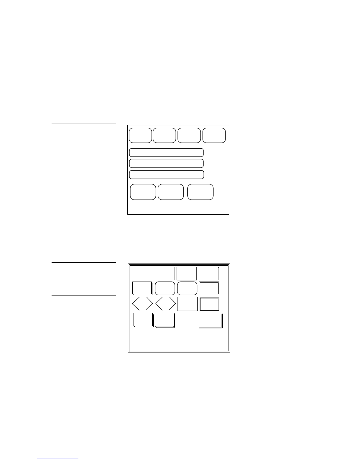
Attributes
RAISED
Use the Attributes page to set the border style and system parameters for the button.
Press the ATTRIBUTES option and a button to open the Attributes page shown in
Figure 120.
Figure 120
Attributes page
Figure 121
Border Options page
Note
The three-dimensional border
option is available in mini-touch
panels equipped with firmware
version 2.0 or higher.
EXIT
CHANNEL
CODE
NONE
NO CHANGE
BORDER
PAGE: NONE
STRING: NONE
FEEDBACK: CHANNEL
EXIT
VARIABLE
TEXT
NONE
COLORS
SET
BRING
BUTTON
TO FRONT
• BORDER Opens the Border Options page (Figure 121) so you can select a
border style.
NO
BORDER
DOUBLE
RAISED
SINGLE
DIAMOND
TRIPLE
SINGLE
WIDE
SINGLE
ROUNDED
DOUBLE
DIAMOND
SHADOWNOBORDER
DOUBLE
WIDE
DOUBLE
ROUNDED
TRIPLE
WIDE
SPECIAL
SINGLE
RAISED
DOUBLE
2
SINGLE
DOUBLE
3
SINGLE
THREE
DIMENSION
Color Active-Matrix LCD Mini-Touch Panels Mini-Touch Panel Program Reference 79
Page 88
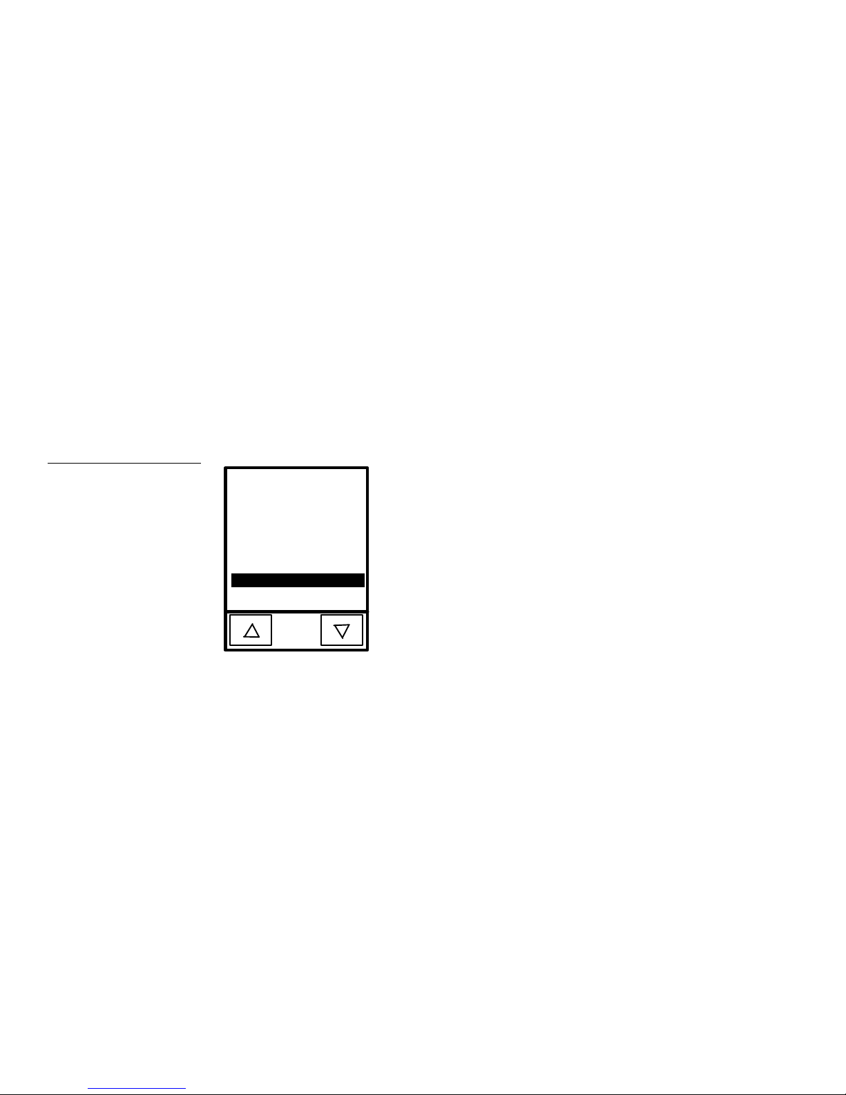
Determine the border style you want to use as they appear on the border style
buttons. The NO BORDER button hides the button for graphic illustrations.
• CHANNEL CODE Opens the number keypad to type the channel code. The
channel code range is 1 through 255. Record the channel code settings if you
want to create duplicate buttons and functions on another page.
• VARIABLE TEXT Opens the number keypad to type the variable text
number. The variable text range is 1 through 255. Record the variable text
setting if you want to create duplicate buttons and functions on another page.
• BRING BUTTON TO FRONT Changes the alignment position of two
buttons. This option stacks buttons for complex page arrangements.
• PAGE Opens the page list (Figure 122) so you can select a page flip.
Figure 122
Page list
* * NONE * *
* * PREVIOUS *
PAGE 4
PAGE 3
PAGE 2
PAGE 1
MAIN PAGE
ENTER
*
Move the highlight bar to a page name, ** NONE **, or ** PREVIOUS ** using
the up and down buttons. Press ENTER to set the page. Press ** PREVIOUS **
to set the button to return to the previous page. Press ** NONE ** to set the
button for no page flip.
• STRING Opens the String Options page in Figure 123. Use this option to
send characters, numbers, messages, or feedback to the control system. The
string options are STANDARD, KEYPAD, and KEYBOARD.
80 Mini-Touch Panel Program Reference Color Active-Matrix LCD Mini-Touch Panels
Page 89

Figure 123
String Options page
STANDARD
KEYPAD
KEYBOARD
STANDARD Opens the keyboard pages for you to type a text string of up to
300 characters. Type the text and press EXIT SAVE to close the keyboard.
When you press the button, the mini-touch panel sends the message to the
AXCESS Control System via the mini-XLR or 4-pin AXlink connector.
Note
You can use hexadecimal
characters such as a ^0D for a
return or ^0A for line feed. You
can use any hexadecimal
character to control external
devices.
KEYPAD Sets the STRING attribute to SPECIAL KEYPAD. The special
keypad option sends the numbers you enter to the control system to perform
an operation defined in the AXCESS software program. When you press the
button, a keypad appears and you enter the numbers and press ENTER. The
mini-touch panel sends the numbers to the AXCESS Control System to
perform an operation. Refer to the AXCESS Programming Guide for more
information.
KEYBOARD Sets the STRING attribute to SPECIAL KEYBOARD. The
special keyboard option sends messages to the control system to perform an
operation defined in the AXCESS software program. When you press the
button, a keyboard appears and you enter a message and press EXIT
CHANGE. The mini-touch panel sends the message to the AXCESS Control
System to perform an operation. Refer to the AXCESS Programming Guide for
more information.
• FEEDBACK Opens the Feedback page shown in Figure 124. The mini-touch
panel can receive feedback (control signals) from an AXCESS Control System.
You can use the feedback option to designate how a button appears on the
mini-touch panel. Feedback options are NONE, INVERTED CHANNEL,
ALWAYS ON, CHANNEL, and MOMENTARY.
Color Active-Matrix LCD Mini-Touch Panels Mini-Touch Panel Program Reference 81
Page 90

Figure 124
Feedback Options page
NONE
INVERTED
CHANNEL
ALWAYS ON MOMENTARY
CHANNEL
NONE Sets the button feedback to off. This option also sets the button
border and fill to match the CHANNEL OFF settings in the Attributes page.
INVERTED CHANNEL Sets the button border, fill, and text to match the
CHANNEL ON settings in the Attributes page when the assigned button
function is off.
ALWAYS ON Sets the button feedback to on. This option also sets the
button border, fill, and text to match the CHANNEL ON options in the
Attributes page.
CHANNEL Sets the button border, fill, and text to match the CHANNEL ON
options in the Attributes page when the assigned button function is on.
MOMENTARY Sets the button border, fill, and text to match the CHANNEL
ON options in the Attributes page when you press the button regardless of the
assigned function.
• EXIT Closes the Attributes page and returns to the current page.
• EXIT NO CHANGE Cancels changes, closes the Attributes page, and returns
to the current page.
• SET COLORS Press to open the SET COLORS page and set the border, fill,
and text colors for channel off and channel on conditions. The OFF and ON
buttons at the bottom of the page show the color settings.
82 Mini-Touch Panel Program Reference Color Active-Matrix LCD Mini-Touch Panels
Page 91

Save
Press the SAVE option and then a button to copy the button attributes into memory.
Then, you can paste the button onto the current page or onto another page.
Note
You can only have one SETUP
button per page.
Figure 125
Page menu options
Paste
Press the PASTE option and then press the screen to paste the button saved in
memory onto the page.
Page Menu Options
Press PAGE to open the menu options shown in Figure 125.
PAGE: MAIN PAGE
MAIN
PAGE
PASSWD PG FLIP
PAGE COLOR
ADD
COPY
RENAME
DELETE
GO TO
PRINT
SETUP
EXIT
Color Active-Matrix LCD Mini-Touch Panels Mini-Touch Panel Program Reference 83
The options include operations to add, copy, rename, delete, go to a page, password
page-flip, print, and set the colors on the mini-touch panel pages. Press the EXIT
button on the editor bar to close the menu options.
Page 92

Add
LOCK
–
SAVE
Press the ADD option to add a new mini-touch panel page, and then the add page
message to open the keyboard (Figure 126).
Figure 126
Add page message and
keyboard page 1
Note
The new page must have a
button with assigned attributes
before it can be used.
YOU MUST GIVE THE NEW PAGE A
UNIQUE NAME UP TO 20 LETTERS
TOUCH SCREEN TO CONTINUE
Q W E R T
A S D F G
Z X C V
CAP
INTNL
CHARS
SHIFT
SPACE ALT
FONT ABORT
BACK
SPACE
ENTER
DEL
MORE
KEYS
EXIT
Type the page name using the keyboard. You can alternate between keyboard pages
1 and 2 using the MORE KEYS button. Choose EXIT SAVE to store the page name in
memory. Special keyboard keys are MORE KEYS, INTNL CHARS, ALT, ABORT,
and EXIT SAVE.
• MORE KEYS Toggles between keyboard pages 1 and 2.
• INTNL CHARS Changes the keyboard to two additional pages of
international characters for the current character set in use.
• ALT Changes the keyboard to alternate keyboard pages 1 and 2 that contain
additional numbers and punctuation characters .
• ABORT Closes the keyboard without naming the page and returns to the
current page.
• EXIT SAVE Stores the page name and returns to the current page.
84 Mini-Touch Panel Program Reference Color Active-Matrix LCD Mini-Touch Panels
Page 93

Copy
RTA
X
LOCK
BACK
ALT
–
DEL
MORE
KEYS
ABORT
Press the COPY option to copy the current page and then select the copy page
message to open the keyboard (Figure 127).
Figure 127
Copy page message and
keyboard and page 1
YOU MUST GIVE THE NEW PAGE A
UNIQUE NAME UP TO 20 LETTERS
TOUCH SCREEN TO CONTINUE
Q W E
S D F G
Z
CAP
INTNL
CHARS
C V
SHIFTSPACE
FONT
SPACE
ENTER
EXIT
SAVE
Type the new page name using keyboard pages 1 and 2. You can alternate between
keyboard pages 1 and 2 using the MORE KEYS button. Choose EXIT SAVE to store
the page name in memory. Special keyboard keys are MORE KEYS, INTNL CHARS,
ALT, ABORT, and EXIT SAVE.
• MORE KEYS Toggles between keyboard pages 1 and 2.
• INTNL CHARS Changes the keyboard to two additional pages of
international characters for the current character set in use.
Color Active-Matrix LCD Mini-Touch Panels Mini-Touch Panel Program Reference 85
• ALT Changes the keyboard to alternate keyboard pages 1 and 2 that contain
additional numbers and punctuation characters .
• ABORT Closes the keyboard without naming the page and returns to the
current page.
• EXIT SAVE Stores the page name and returns to the current page.
Page 94

Rename
LOCK
–
SAVE
LOCK
SAVE
Press the RENAME option to open keyboard pages 1 and 2 shown in Figure 128.
Figure 128
Keyboard pages 1 and 2
NEW PAGE
Q W E R T
A S D F G
Z X C V
CAP
INTNL
CHARS
SHIFTSPACE ALT
FONT ABORT
BACK
SPACE
ENTER
MORE
KEYS
EXIT
DEL
NEW PAGE
Y U I O P
H J K L
< >
SHIFTSPACE ALT
FONT ABORT
CAP
B
N M
INTNL
CHARS
BACK
SPACE
ENTER
:
DEL
MORE
KEYS
EXIT
Page 1 Page 2
Choose EXIT SAVE to store the page name in memory. Special keyboard keys are
MORE KEYS, INTNL CHARS, ALT, ABORT, and EXIT SAVE.
• MORE KEYS Toggles between keyboard pages 1 and 2.
• INTNL CHARS Changes the keyboard to two additional pages of
international characters for the current character set in use.
• ALT Changes the keyboard to alternate keyboard pages 1 and 2 that contain
additional numbers and punctuation characters .
• ABORT Closes the keyboard without naming the page and returns to the
current page.
• EXIT SAVE Stores the page name and returns to the current page.
86 Mini-Touch Panel Program Reference Color Active-Matrix LCD Mini-Touch Panels
Page 95

Delete
Press the DELETE option to open the delete decision box shown in Figure 129.
Figure 129
Delete decision box
Note
You cannot delete the Main
page or Page 1.
Figure 130
Page list
ARE YOU SURE YOU WANT
YES
TO DELETE THIS PAGE ?
NO
• YES Deletes the page and returns to the Main page.
• NO Cancels the deletion process and returns to the current page.
Go to
Press the GO TO option to open the page list shown in Figure 130.
* * NONE * *
* * PREVIOUS *
MAIN PAGE
PAGE 1
PAGE 2
ENTER
*
Color Active-Matrix LCD Mini-Touch Panels Mini-Touch Panel Program Reference 87
With the up and down buttons, move the highlight bar to a page name, ** NONE **,
or ** PREVIOUS **, and press ENTER to go to that page.
• Up arrow Moves the highlight bar up.
• Down arrow Moves the highlight bar down.
• ENTER Resets the screen to the new page.
Page 96

Note
Do not use the PASSWD PG
FLIP option unless you know
the current password. Refer to
Page Password in the Setup
Page subsection.
Passwd pg flip
Press the PASSWD PG FLIP (password page flip) option and then press the screen to
add a password-protected button on the current page. Press BUTTON on the editor
bar and then ATTRIBUTES. Press the new button to open the Attributes page
(Figure 131).
Figure 131
Attributes page
Figure 132
Page list
EXIT
CHANNEL
CODE
NONE
EXIT
NO CHANGE
BORDER
PAGE: NONE
STRING: NONE
FUNCTION: PASSWORD PAGE FLIP
SET
COLORS
BRING
BUTTON
TO FRONT
Press PAGE to open the page list ( Figure 132).
* * NONE * *
* * PREVIOUS *
MAIN PAGE
PAGE 1
PAGE 2
*
ENTER
Move the highlight bar to the target page using the up and down buttons. Press
ENTER and then EXIT twice to set the new button and page flip.
• Up arrow Moves the highlight bar up.
• Down arrow Moves the highlight bar down.
88 Mini-Touch Panel Program Reference Color Active-Matrix LCD Mini-Touch Panels
Page 97

• ENTER Sets the page flip to the new page.
Press the new button to open the page password keypad.
Note
You can reset the password
number with the PAGE
PASSWORD button in the
Protected Setup page.
Figure 133
Transfer decision box
Type 1988 (system default), or your personal page password, and press ENTER to
flip to the new page.
• CLEAR Clears the keypad number.
• ENTER Sets the page password number, closes the keypad, and flips to the
new password-protected page. The password-protected page will not open if
you enter the wrong password.
Print
Press the PRINT option to open a decision box and send a printable image of the
current page to a PC via the AXlink or 4-pin header on the mini-touch panel. The PC
must be running the or TPDesign software programs before you send the print file.
Refer to TPDOC or TPDesign instruction manuals for more information.
YES
PRESS YES FOR BUS
TRANSFER. PRESS NO
FOR RS232 (9 PIN D).
NO
• YES Receives the PC file over the mini-XLR or AXlink connector on the
mini-touch panel, and opens the decision box in Figure 128.
• NO Receives the PC file over the 4-pin header on the UniMount and rack-
mount mini-touch panels, and opens the decision box in Figure 134.
Figure 134
YES
Start or quit decision box
PRESS YES TO START.
PRESS NO TO QUIT.
NO
• YES Sends the print file to the PC. The mini-touch panel returns to the page
assigned as the startup page when the file transfer is complete.
• NO Cancels the file transfer and returns to the current page.
Color Active-Matrix LCD Mini-Touch Panels Mini-Touch Panel Program Reference 89
Page 98

Page color
V
A
Press the PAGE COLOR button to open the page shown in Figure 135.
Figure 135
Set Choose Color page
CHOOSE COLOR EXIT
DARK
BLACK
DARK
MAGENTA
MEDIUM
CREAM
GRAY
YELLOW BLUE MAGENTA CYAN WHITE
RED
DARK
CYAN
MICROSOFT
MOUSE
DARK
GREEN
LIGHT
GRAY
DARK
GRAY
DARK
YELLOW
MONEY
GREEN
DARK
BLUE
SKY
BLUE
RED GREEN
I
D
E
O
B
O
R
T
Then, select the video or background color for the mini-touch panel pages.
• VIDEO Sets the mini-touch panel pages to display incoming video signals
in the background. The background appears black if no incoming video
signals are present in the mini-touch panel.
• ABORT Returns to the Setup page.
Icons Menu Options
Press ICONS to open the menu options shown in Figure 136.
Figure 136
Icons options list
90 Mini-Touch Panel Program Reference Color Active-Matrix LCD Mini-Touch Panels
BUTTON PAGE
ICONS
SYSTEM
TIME
DATE
E TIMER
16 CHAR TERM
32 CHAR TERM
VERTICAL GRAPH
ICON FEEDBACK
JOY STICK
DRAWINGS
BRIGHTNESS
VIDEO SETUP
EXIT
Page 99

The options include operations to set time, date, elapsed timers, messages, graphs,
icon feedback, joy sticks, drawings, brightness setup, and video settings. Press the
EXIT button to close the Icons options list.
Time
Note
You can have one time button
per page.
Note
You can have one date button
per page.
Figure 137
E TIMER button
Press TIME and the screen to add a time button to the current page. The onboard
clock in the mini-touch panel maintains time. Use the SET TIME AND DATE button
in the Setup page to reset the clock and time display.
Date
Press DATE and the screen to add a date button to the current page. The onboard
clock in the mini-touch panel maintains the date. Use the SET TIME AND DATE
button in the Setup page to reset the clock and date display. Reset the button size
using the ATTRIBUTES option in the Button menu options.
E timer
Press E TIMER and the screen to add an elapsed timer button ( Figure 137) to the
current page.
E TIMER
9:59:59
RESET START
Color Active-Matrix LCD Mini-Touch Panels Mini-Touch Panel Program Reference 91
You can use the elapsed timer to time an event for up to 10 hours . Use the
ATTRIBUTE option in the Button menu to move the timer on the screen.
• RESET Resets the elapsed timer to 0:00:00.
• START Starts the elapsed timer and changes the button name to PAUSE.
• PAUSE Pauses the elapsed timer and changes the button name to START.
Press the button again to continue timing the event.
Page 100

Figure 138
16 char term
Press the 16 CHAR TERM option and the screen to add a 16-character message to all
the touch panel pages. If the message is longer than 16 characters, the mini-touch
panel scrolls the message (one per page) across the window like a billboard.
32 char term
Press the 32 CHAR TERM option and the screen to add a 32-character message to all
the touch panel pages. If the message is longer than 32 characters, the mini-touch
panel scrolls the message (one per page) across the window like a billboard.
Vertical graph
Press the VERTICAL GRAPH option and the screen to add a bargraph or slider to
the current page. Feedback for graph or slider response comes from the AXCESS
Control System. Use the RESIZE option in the Button menu to resize the vertical
graph. Use the ATTRIBUTES option in the Button menu to set the attributes in the
Attributes page (Figure 138).
Attributes page
EXIT
LEVEL
CODE
1
SET
COLORS
BRING
BUTTON
TO FRONT
CHANNEL
CODE
NONE
FEEDBACK: BAR GRAPH
FUNCTION: VERTICAL DISPLAY
EXIT
NO CHANGE
• CHANNEL CODE Opens the keypad to set the channel code for the vertical
graph. The channel code range is 1 through 255. Keep track of channel code
settings to create duplicate vertical graphs with identical functions on another
page.
92 Mini-Touch Panel Program Reference Color Active-Matrix LCD Mini-Touch Panels
 Loading...