

Page 1

instruction manual
To u c h Panels and Accessories
10.4" Touch Panels
(Firmware version G3)
Page 2

AMX Limited Warranty and Disclaimer
AMX Corporation warrants its products to be free of defects in material and workmanship under normal use for three
(3) years from the date of purchase from AMX Corporation, with the following exceptions:
• Electroluminescent and LCD Control Panels are warranted for three (3) years, except for the display and touch
overlay components that are warranted for a period of one (1) year.
• Disk drive mechanisms, pan/tilt heads, power supplies, and MX Series products are warranted for a period of one
(1) year.
• AMX Lighting products are guaranteed to switch on and off any load that is properly connected to our lighting
products, as long as the AMX Lighting products are under warranty. AMX Corporation does guarantee the
control of dimmable loads that are properly connected to our lighting products. The dimming performance or
quality cannot be guaranteed due to the random combinations of dimmers, lamps and ballasts or transformers.
• Unless otherwise specified, OEM and custom products are warranted for a period of one (1) year.
• AMX Software is warranted for a period of ninety (90) days.
• Batteries and incandescent lamps are not covered under the warranty.
This warranty extends only to products purchased directly from AMX Corporation or an Authorized AMX Dealer.
All products returned to AMX require a Return Material Authorization (RMA) number. The RMA number is
obtained from the AMX RMA Department. The RMA number must be clearly marked on the outside of each box.
The RMA is valid for a 30-day period. After the 30-day period the RMA will be cancelled. Any shipments received
not consistent with the RMA, or after the RMA is cancelled, will be refused. AMX is not responsible for products
returned without a valid RMA number.
AMX Corporation is not liable for any damages caused by its products or for the failure of its products to perform.
This includes any lost profits, lost savings, incidental damages, or consequential damages. AMX Corporation is not
liable for any claim made by a third party or by an AMX Dealer for a third party.
This limitation of liability applies whether damages are sought, or a claim is made, under this warranty or as a tort
claim (including negligence and strict product liability), a contract claim, or any other claim. This limitation of
liability cannot be waived or amended by any person. This limitation of liability will be effective even if AMX
Corporation or an authorized representative of AMX Corporation has been advised of the possibility of any such
damages. This limitation of liability, however, will not apply to claims for personal injury.
Some states do not allow a limitation of how long an implied warranty last. Some states do not allow the limitation or
exclusion of incidental or consequential damages for consumer products. In such states, the limitation or exclusion of
the Limited Warranty may not apply. This Limited Warranty gives the owner specific legal rights. The owner may
also have other rights that vary from state to state. The owner is advised to consult applicable state laws for full
determination of rights.
EXCEPT AS EXPRESSLY SET FORTH IN THIS WARRANTY, AMX CORPORATION MAKES NO
OTHER WARRANTIES, EXPRESSED OR IMPLIED, INCLUDING ANY IMPLIED WARRANTIES OF
MERCHANTABILITY OR FITNESS FOR A PARTICULAR PURPOSE. AMX CORPORATION
EXPRESSLY DISCLAIMS ALL WARRANTIES NOT STATED IN THIS LIMITED WARRANTY. ANY
IMPLIED WARRANTIES THAT MAY BE IMPOSED BY LAW ARE LIMITED TO THE TERMS OF THIS
LIMITED WARRANTY.
Page 3

Table of Contents
i
10.4" Touch Panels
Table of Contents
Product Information .................................................................................................1
Specifications .................................................................................................................... 1
Cleaning the Touch Overlay.............................................................................................. 2
Installation .................................................................................................................3
Mounting the Touch Panel ................................................................................................ 3
Decor style panels with low-profile Backboxes ........................................................................ 3
Installing touch panels and a CB-TP3 Backbox (plasterboard)................................................ 6
Installing rack-mount panels (AXM-CA10/PB) ......................................................................... 8
Wiring the Touch Panel ..................................................................................................... 8
Preparing captive wires ............................................................................................................ 8
Wiring guidelines...................................................................................................................... 8
Using the PSN connector for power......................................................................................... 9
Using AXlink for data and power .............................................................................................. 9
Using AXlink for data with a +12 VDC power supply ............................................................. 10
Using the (DB9) RS-232 connector for mouse control or data............................................... 11
Using the VGA IN HD-15 (male) high-density connector ....................................................... 12
Designing Touch Panel Pages ..............................................................................15
Buttons ............................................................................................................................ 15
Activating Edit Mode........................................................................................................ 16
Setting the Device Base .................................................................................................. 18
Setting the Device Used.................................................................................................. 18
Adding a Page................................................................................................................. 18
Setting the page color ............................................................................................................ 18
Adding a Button............................................................................................................... 18
Resizing a button ................................................................................................................... 19
Defining On-Screen and External Button Properties....................................................... 19
Setting the channel code........................................................................................................ 19
Setting the variable text code................................................................................................. 20
Setting the page flip ............................................................................................................... 20
Setting the button colors for channel-off conditions ............................................................... 21
Adding text, icons, and bitmaps to a button ........................................................................... 21
Using TPDesign3 to Download Bitmaps, Icons, and Fonts............................................. 21
Creating a Bargraph and Joystick ................................................................................... 22
Adding a bargraph or joystick button...................................................................................... 22
Setting Bargraph and Joystick Properties ....................................................................... 22
Setting the level code............................................................................................................. 22
Page 4

ii
10.4" Touch Panels
Table of Contents
Programming ..........................................................................................................25
Serial Commands............................................................................................................ 25
System Send_Commands .............................................................................................. 28
Video Send_Commands ................................................................................................. 33
VGA Send_Commands................................................................................................... 35
Programming Numbers ................................................................................................... 37
Shorthand Send_Commands.......................................................................................... 38
Color Send_Commands.................................................................................................. 43
Variable Text Send_Commands ..................................................................................... 45
Shorthand Variable Text Commands .............................................................................. 47
Button String Commands................................................................................................ 50
Upgrading the Firmware ........................................................................................53
Upgrading the Firmware Using NetLinx Studio ............................................................... 53
Upgrading Firmware through a COM port.............................................................................. 53
Upgrading the Firmware through an IP Address.................................................................... 55
Upgrading the Firmware Using SoftROM........................................................................ 57
Configuration.......................................................................................................................... 58
Downloading the Firmware .................................................................................................... 58
Changing the LCD Viewing Angle ........................................................................ 59
Changing the Viewing Angle to 6 o’clock (podium mount).............................................. 59
Replacing the Batteries .........................................................................................61
Page 5
Product Information
1
10.4"Touch Panels
Product Information
The AMX™ CA10, CV10 and CG10 touch panels contain a 10.4", 256-color active matrix liquid
crystal display (LCD). The self-contained enclosures use a microprocessor to control a wide range
of multimedia equipment. The TPDesign3 touch panel design program makes it possible to create
custom pages with buttons, icons, sliders, bargraphs, time displays, logos, and drawings.
All Decor-style references in this manual relate to wall mounted panels.
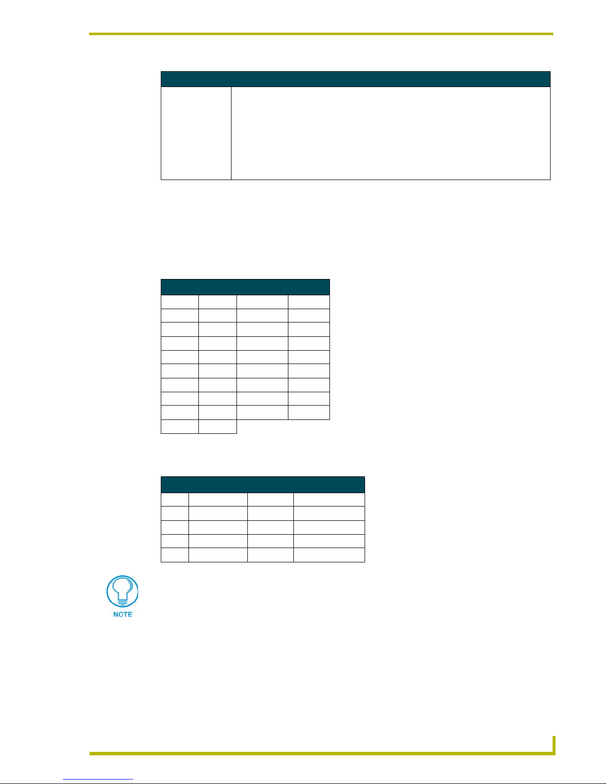
The table below lists the panel types and product names discussed in this manual.
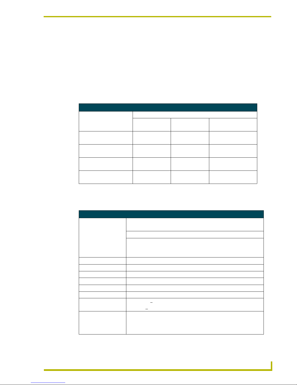
Specifications
The table below lists the CA10, CV10, and CG10 specifications.
Touch Panel Types and Product Names
Product Names
Panel Types Standard
(Color Active)
Video
(NTSC/PAL)
Graphic
(VGA/SVGA/XGA/DOS)
Free standing:
TiltScreen AXT-CA10 AXT-CV10 AXT-CG10
Wall Mount:
Decor style AXD-CA10 AXD-CV10 AXD-CG10
Rack Mount:
Rack-mount AXM-CA10 AXM-CV10 AXM-CG10
Pushbutton AXD-CA10/PB
AXM-CA10/PB
AXD-CV10/PB
AXM-CV10/PB
AXD-CG10/PB
AXM-CG10/PB
Specifications
Dimensions (HWD):
AXD - Decor Wall Mount • 8.88" x 12.88" x 2.19" (22.56 cm x 32.72 cm x 5.56 cm)
AXM- Rack-Mount • 8.72" x 19.00" x 1.78" (22.15 cm x 48.26 cm x 4.52 cm)
AXT- TiltScreen • Base (WD): 11.46" x 9.46" (29.11 cm x 24.03 cm)
• Height lowered: 4.14" (10.52 cm)
• Height raised: 9.84" (25.0 cm)
Display Area (HV) • 211.1 mm x 158.4 mm
Display Colors • 256K colors
Pixel Resolution • 640 x 480 pixels
Dot Pixel Pitch • 0.33 mm
Contrast Ratio • 300: 1
Brightness • 350 cd/m
2
Viewing Angles • Horizontal: + 50° (left/right sides)
• Vertical: +
40° (up/down)
Wider Viewing Angle • Without image reversal: Up side (12 o’clock normal scan) and
Down side (6 o’clock reverse scan)
• With contrast ratio: Up side (12 o’clock reverse scan) and
Down side (6 o’clock normal scan)
Page 6
Product Information
2
10.4" Touch Panels
Cleaning the Touch Overlay
You should clean the touch screen overlay after each day’s use. Always use clean cotton cloths, and
a spray bottle of cleaning solution consisting of 50% isopropyl alcohol and 50% water.
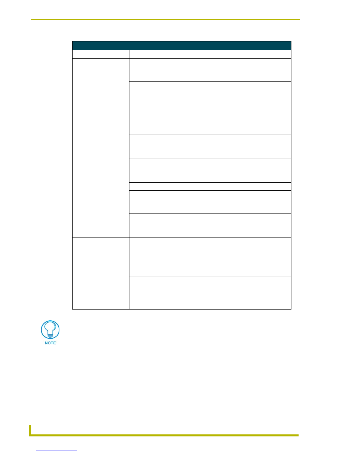
Specifications (Cont.)
Power 12 VDC @ 1 A
Memory Standard: 5 MB (4 MB flash)
Weight:
Decor • 6.0 lbs. (2.7 kg)
Rack-mount • 6.0 lbs. (2.7 kg)
TiltScreen • 4.6 lbs. (2.1 kg)
VGA Input Resolutions:
640 x 400 (DOS)
(The frame frequency [FF] calculations are based on monitor type and VGA
settings.)
FF: 70 Hz
640 x 480 (VGA) FF: 60 and 72 Hz
800 x 600 (SVGA) FF: 52, 60, and 72 Hz
1024 x 768 (XGA) FF: 60 and 70 Hz
Rear Panel Connectors:
AXlink • 4-pin AXlink data/power bus jack
RS-232 • DB9 male connector for PC data transmission or Microsoft
®
mouse control
Video • RCA female connector (Color Video/Graphic AXT models only)
• BNC female connector (Color Video/Graphic AXD and AXM models)
Graphics • 15-pin HD-15 (high-density) male connector (Color Graphic model only)
PWR • 2-pin 12 VDC power supply jack
Enclosure:
Decor Metal with black matte finish, screwed security overlay, CB-TP3 Backbox
TiltScreen Black plastic with matte finish
Rack-mount Metal with black matte finish, engraved overlay, low-profile Backbox
Character Support • Unicode character support
Included Accessories: • 4-pin AXlink data/power connector (41-0049)
• 2-pin PWR connector (41-0021)
Optional Accessories:
Decor • Up to 24 external pushbuttons
• Backbox (CB-TP3) (FG025-10)
Rack-mount • Up to 24 external pushbuttons
TiltScreen • Install Kit (SA2010-01)
4-pin AXlink data/power connector (41-0049)
Tie wrap (45-0009)
Cable tie holder (45-0009-01)
CG10 panels are capable of receiving a VGA signal. These VGA signals can be
displayed on a touch panel as a background image and NOT within a video button. A
Video signal can only be displayed within a Video WIndow Button. Refer to the G3
Firmware manual for more detailed information.
Page 7
Installation
3
10.4" Touch Panels
Installation
Mounting the Touch Panel
The following paragraphs describe mounting the Decor and rack-mount touch panels. TiltScreen
touch panels can be placed on any flat surface.
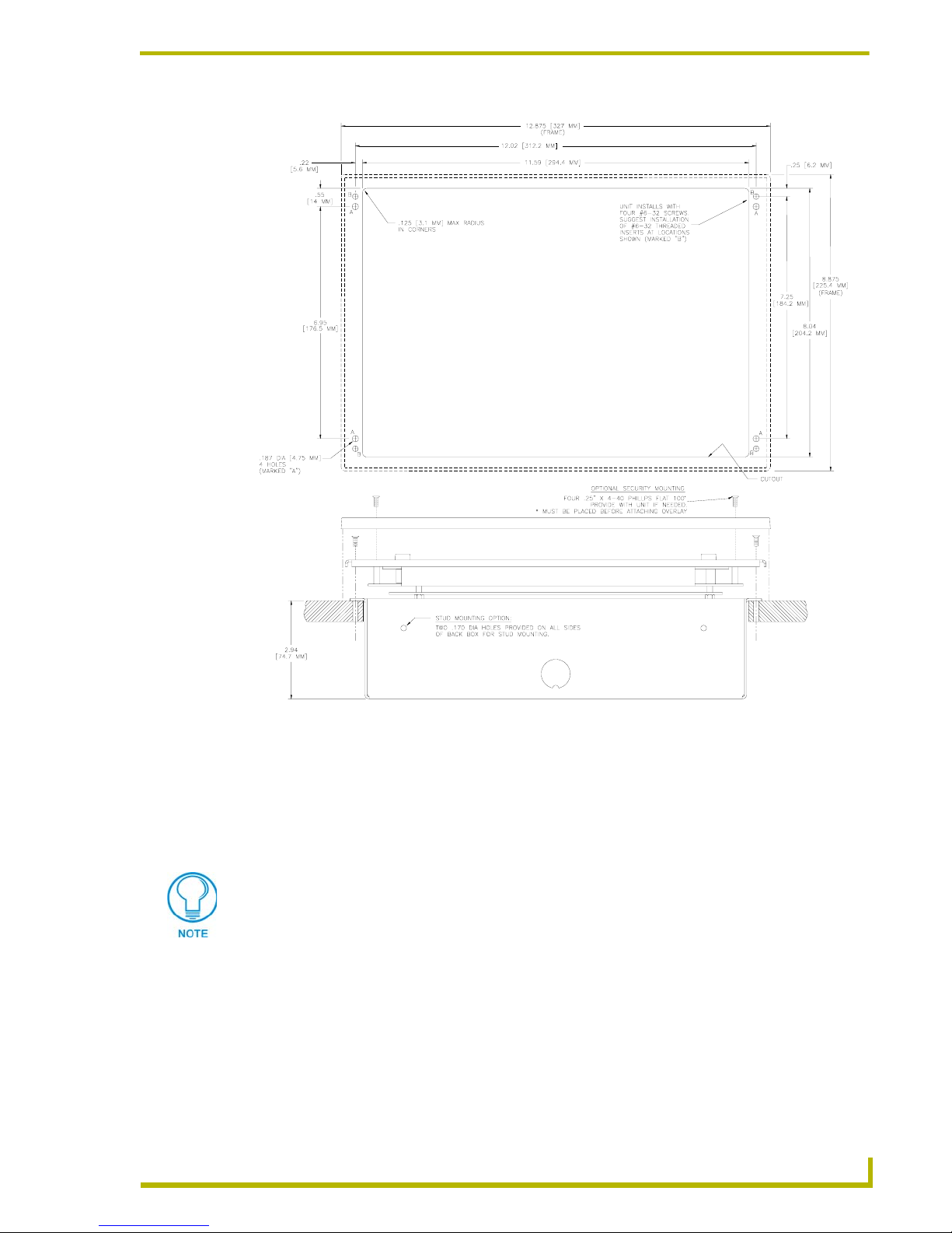
Decor style panels with low-profile Backboxes
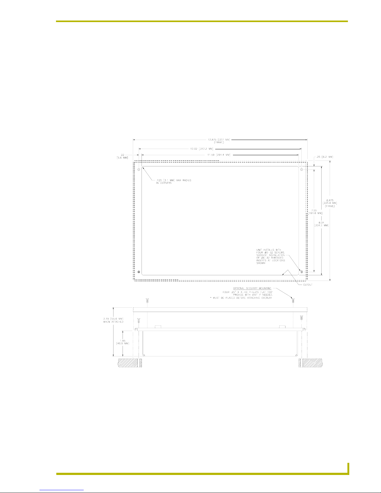
1. Cut out the surface using the dimensions shown in FIG. 1.
2. Carefully insert a flat-blade screwdriver into the release slot on the touch panel’s faceplate and
remove the engraved overlay.
3. Place the touch panel into the cutout and mark the screw insert positions, as shown in FIG. 1.
4. Remove the touch panel and drill four #6-32 insert holes. Then, place a threaded insert into
each hole.
FIG. 1 AXD-CA10 and low profile Backbox cutout dimensions
Page 8
Installation
4
10.4" Touch Panels
5. Disconnect the AXlink connector from the Central Controller, RS-232 connector, and the
optional graphic/video wiring from the external RS-232 device connected to the source
equipment.
6. Thread the incoming AXlink, RS-232, and optional graphic/video wiring through the low-
profile Backbox.
7. Fasten the low-profile Backbox using the #6-32 machine screws supplied with the enclosure.
8. Attach the data and power wiring to the touch panel.
9. Test the connection by reconnecting the AXlink connector to the Central Controller, RS-232
connector, and optional graphic/video wiring to the source equipment. Before continuing,
disconnect all connections until panel installation is complete.
10. Fasten the touch panel and low-profile Backbox using the #6-32 machine screws supplied with
the enclosure panel.
11. Place the faceplate onto the bezel. You can also secure the faceplate to the bezel using the four
Phillips flathead security screws. Once attached to the faceplate, the security screws cannot be
replaced without removing the overlay.
12. Remove the backing from the adhesive tape strips located on the front of the panel; press the
engraved overlay onto the faceplate.
13. Reconnect the AXlink wiring to the Central Controller, RS-232 wiring to the mouse (if used),
and optional graphic/video wiring to the source equipment. The touch panel beeps on power-
up. Refer to the Wiring the Touch Panel section on page 8 for complete information.
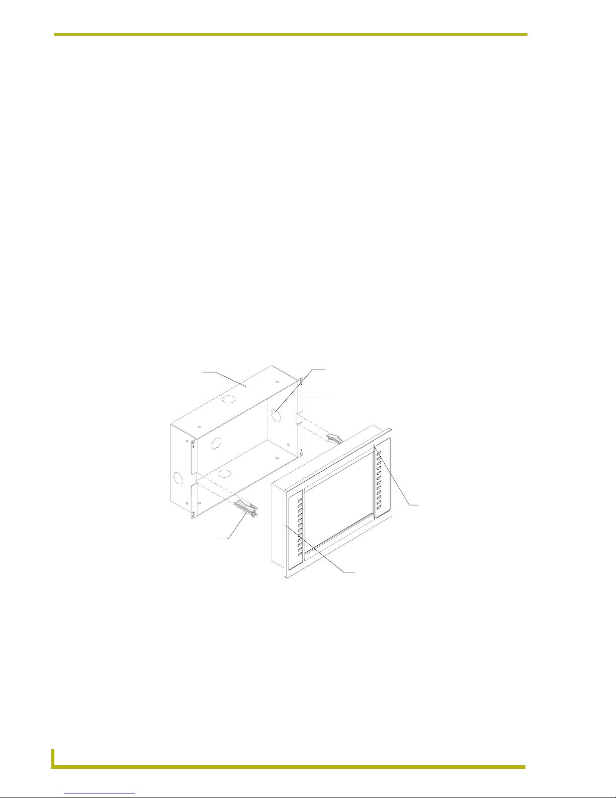
Installing touch panels and a CB-TP3 Backbox (solid surface)
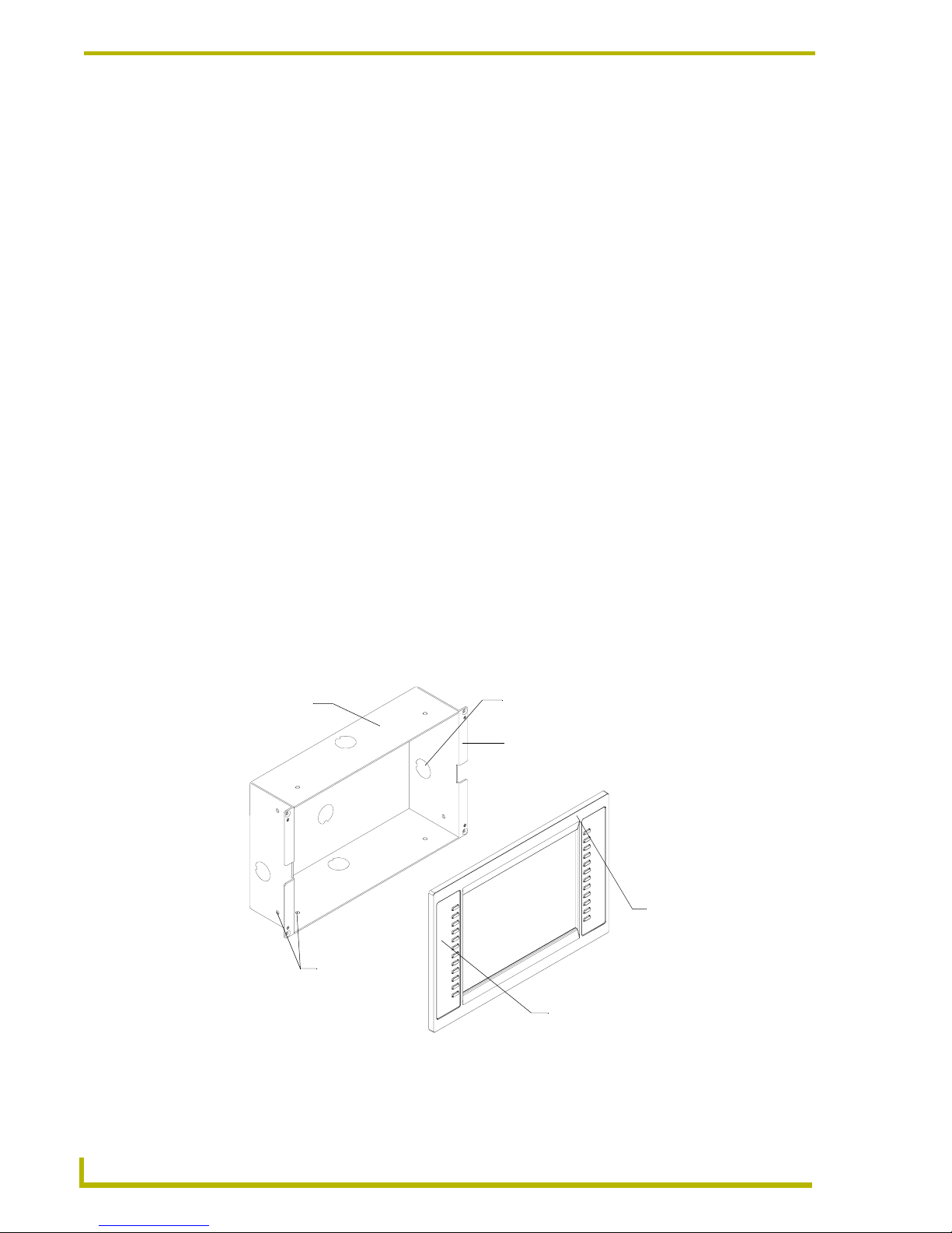
FIG. 2 shows an AXD-CA10/PB and CB-TP3 UniMount Backbox for solid surfaces.
1. Cut out the surface using the dimensions shown in FIG. 3.
FIG. 2 AXD-CA10/PB and CB-TP3 for solid surfaces
CB-TP3 Unimount
Backbox enclosure
Knockout
Solid surface mounting flanges
Stud mounting
holes
Engraved overlay
AXD-CA10/PB
faceplate
Page 9
Installation
5
10.4" Touch Panels
2. Carefully insert a flat-blade screwdriver into the release slot on the touch panel’s bezel and
remove the engraved overlay.
3. Lay the touch panel facedown on a soft cloth and remove the screws from the low-profile
Backbox; remove the Backbox and discard.
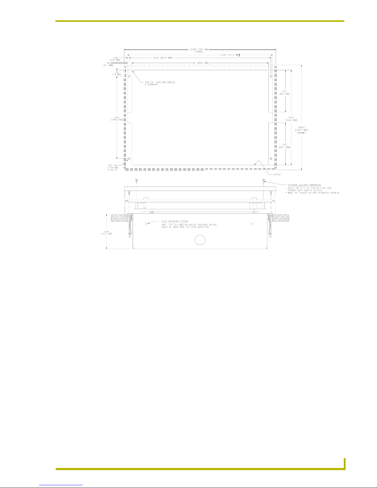
4. Place the CB-TP3 into the cutout and mark the threaded insert positions, as shown in FIG. 3.
5. Remove the CB-TP3 and drill eight holes (A and B) for the panel (FIG. 3). Then, place #6-32
threaded inserts (or screw anchors) into the four holes marked ‘B’ (FIG. 3).
6. Disconnect the AXlink connector from the Central Controller, RS-232 connector, and the
optional graphic/video wiring from the source equipment.
7. Remove one or more knockouts to accommodate the wiring.
8. Thread the incoming AXlink, RS-232, and optional graphic/video wiring through the CB-TP3
knockouts. Refer to the Wiring the Touch Panel section on page 8 for pinout descriptions.
FIG. 3 Decor style (AXD) and CB-TP3 cutout dimensions (solid surfaces)
The CB-TP3 can also be mounted to wood or metal studs using the pre-drilled stud
mounting holes.
Page 10
Installation
6
10.4" Touch Panels
9. Fasten the CB-TP3 to the solid surface using the supplied mounting screws. The touch panel
must be installed with the release slot at the bottom.
10. Connect the AXlink, RS-232, and optional graphic/video wiring to the touch panel.
11. Test the connection by reconnecting the AXlink connector to the Central Controller and the
optional video wiring to the video source. The panel beeps on power-up. Before continuing,
disconnect all connections until panel installation is complete.
12. Fasten the touch panel to the CB-TP3 using the #6-32 screws supplied with the panel.
13. Place the Decor-style faceplate onto the bezel. You can also secure the faceplate to the bezel
using the four Phillips flathead security screws.
14. Remove the backing from the adhesive tape strips; press the engraved overlay onto the
faceplate. Once attached to the faceplate, the security screws cannot be replaced without
removing the overlay.
15. Reconnect the AXlink wiring to the Central Controller, RS-232 wiring to the mouse (if used),
and optional graphic/video wiring to the source equipment. The touch panel will beep on
power-up.
Installing touch panels and a CB-TP3 Backbox (plasterboard)
FIG. 4 shows the AXD-CA10/PB and CB-TP3 Backbox for plasterboard.
1. Cut out the surface using the dimensions shown in FIG. 5.
2. Carefully insert a flat-blade screwdriver into the release slot on the touch panel's faceplate and
remove the engraved overlay.
3. Lay the touch panel facedown onto a soft cloth and remove the screws from the low-profile
Backbox. Remove the Backbox and discard.
4. Place the CB-TP3 into the cutout and mark the threaded insert positions (FIG. 5).
FIG. 4 AXD-CA10/PB and CB-TP3 Backbox (plasterboard)
CB-TP3 Unimount
Backbox enclosure
Knockout
Plasterboard surface mounting flanges
Engraved overlay
AXD-CA10/PB
faceplate
Expansion clips
Page 11
Installation
7
10.4" Touch Panels
5. Remove the CB-TP3 and drill four #6-32 insert holes. Then, place a threaded insert (or screw
anchor) into each hole.
6. Disconnect the AXlink connector from the Central Controller, RS-232 connector, and the
optional graphic/video wiring from the source equipment.
7. Remove one or more knockouts to accommodate the wiring as required.
8. Thread the incoming AXlink, RS-232 connector, and the optional graphic/video wiring
through the CB-TP3 knockouts. Refer to Wiring the Touch Panel section on page 8 for more
information.
9. Fasten the CB-TP3 to the plasterboard using the expansion screws supplied with the enclosure.
10. Connect the AXlink, RS-232, and the optional graphic/video wiring to the touch panel.
11. Test the connection by reconnecting the AXlink connector to the Central Controller and the
optional video wiring to the video equipment. The panel beeps on power-up. Before
continuing, disconnect all connections until panel installation is complete.
12. Fasten the touch panel to the CB-TP3 with the #6-32 screws supplied with the panel.
13. Place the Decor-style faceplate onto the bezel. You can also secure the faceplate to the bezel
using the four Phillips flat-head security screws.
FIG. 5 Decor style (AXD) and CB-TP3 cutout dimensions for plasterboard
Page 12

Installation
8
10.4" Touch Panels
14. Remove the backing from the adhesive tape strips; press the engraved overlay onto the
faceplate. Once attached to the faceplate, the security screws cannot be replaced without
removing the overlay.
15. Reconnect the AXlink wiring to the Central Controller, RS-232 wiring to the mouse (if used),
and optional graphic/video wiring to the source equipment. The touch panel beeps on power-
up.
Installing rack-mount panels (AXM-CA10/PB)
1. Thread the incoming AXlink, RS-232, and optional graphic/video wiring through the opening
in the equipment rack.
2. Disconnect the AXlink connector from the Central Controller, the RS-232, and optional
graphic/video wiring from the source equipment.
3. Insert the touch panel into the equipment rack. Line up the top-left and bottom-right screw
holes and start tightening the #6-32 screws. Then, tighten the bottom-left and top-right screws.
4. Connect the AXlink wiring to the Central Controller, RS-232, and optional graphic/video
wiring to the touch panel. Refer to the Wiring Guidelines table for pinout descriptions. The
touch panel beeps on power-up.
Wiring the Touch Panel
The touch panels use a 4-pin AXlink connector for power and data. If the distance between the
panel and Central Controller exceeds power consumption limits, you must connect an optional
12 VDC power supply to the 2-pin PWR connector.
Preparing captive wires
You need a wire stripper, soldering iron, and flat-blade screwdriver to prepare and connect the
captive wires.
1. Strip 0.25 inch of wire insulation off all wires.
2. Insert each wire into the appropriate opening on the connector according to the wiring
diagrams and connector types described in this subsection.
3. Turn the flat-blade screws clockwise to secure the wire in the connector. Do not over-torque
the screws; doing so can bend the seating pin and damage the connector.
Wiring guidelines
The touch panels require 12 VDC power to operate properly. The touch panel can use either a
PSN2.8 (if the power is being supplied only to the touch panel) or a PSN6.5 power supply (if the
power is being routed through the touch panel to power another device). The Central Controller
supplies power via the AXlink cable or external 12 VDC power supply. The maximum wiring
distance between the Central Controller and touch panel is determined by power consumption,
supplied voltage, and the wire gauge used for the cable. The table below lists wire sizes and the
maximum lengths allowable between the touch panel and Central Controller.
Do not connect power to the touch panel until the wiring is complete. If you are using
a 12 VDC power supply, apply power to the touch panel only after installation is
complete.
Page 13
Installation
9
10.4" Touch Panels
The maximum wiring lengths for using AXlink power are based on a minimum of 13.5 VDC
available at the Central Controller's power supply. Refer to the Specifications section on page 1 for
more information on power requirements.
If you install the touch panel farther away from the control system than recommended in the Wiring
Guidelines table, connect an external 12 VDC power supply to the 2-pin PWR connector on the
touch panel.
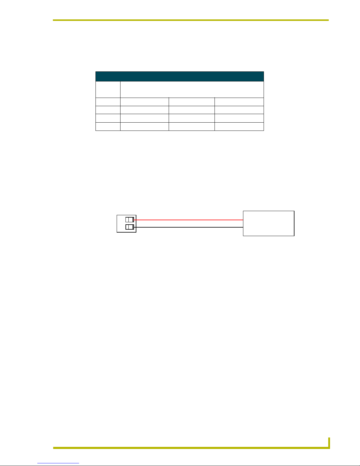
Using the PSN connector for power
To use the 2-pin mini-Phoenix power supply jack for power transfer from the PSN power supply,
the incoming PWR and GND cable from the PSN must be connected to the corresponding location
on the 2-pin AXlink connector (FIG. 6).
1. Insert the PWR and GND wires into the terminal end of the PSN 2-pin AXlink cable.
2. Tighten the clamp to secure the two wires.
3. Verify the connection of the other end to the 2-pin 3.5 mm mini-Phoenix on the PSN.
Using AXlink for data and power
Connect the Central Controller's AXlink connector to the AXlink connector on the touch panel for
data and 12 VDC power as shown in FIG. 7.
Wiring Guidelines
Maximum Wiring Length
Wire Size Color Active Color Graphic Color Video
18 AWG 143.14 feet (43.63 m) 93.90 feet (28.62 m) 130.05 feet (39.64 m)
20 AWG 90.56 feet (27.60 m) 59.41 feet (18.11 m) 78.17 feet (23.83 m)
22 AWG 56.46 feet (17.21 m) 37.04 feet (11.29 m) 48.73 feet (14.85 m)
24 AWG 35.59 feet (10.85 m) 23.35 feet (7.12 m) 30.72 feet (9.36 m)
FIG. 6 Power connector wiring diagram
PWR +
GND -
To the panel
To the PSN Power Supply
(terminal end)
(either a PSN2.8 or PSN6.5)
Page 14
Installation
10
10.4" Touch Panels
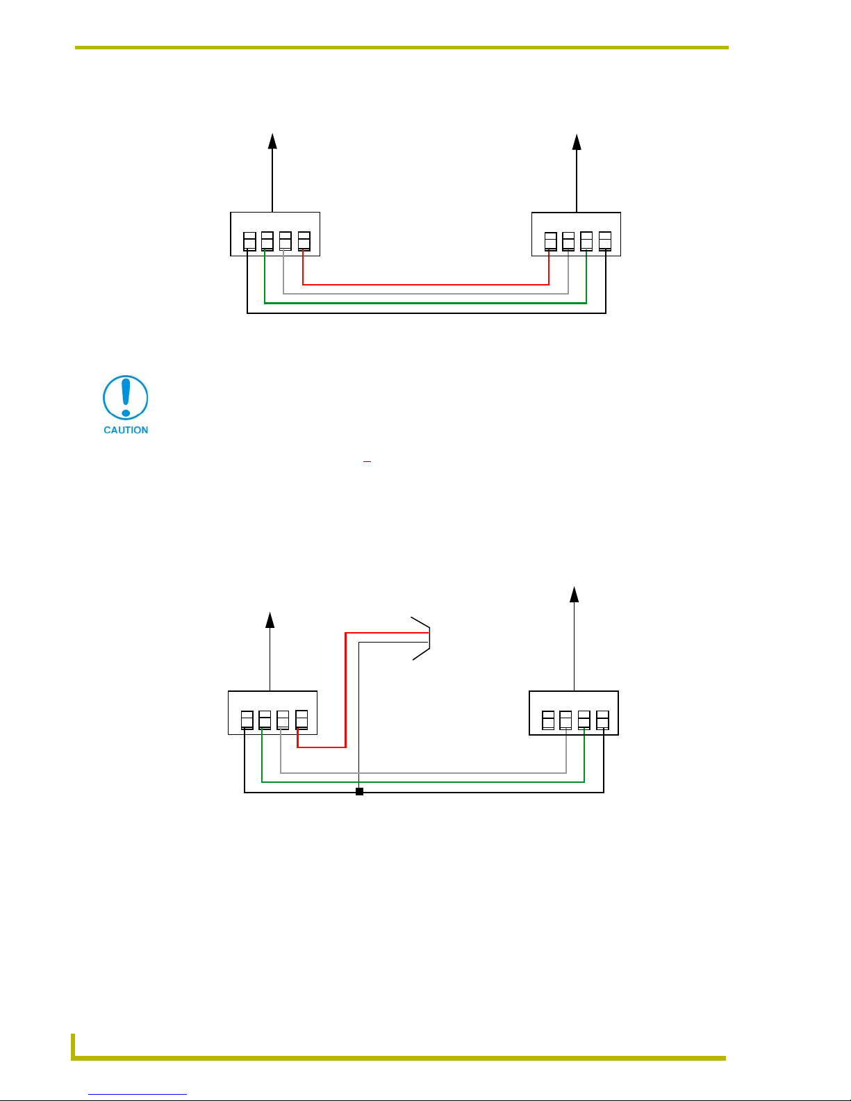
Using AXlink for data with a +12 VDC power supply
To use the AXlink 4-pin connector for data communication with the Central Controller and power
transfer from a power supply, the incoming PWR and GND cable from the power supply must be
connected to the AXlink cable connector going to the touch panel. FIG. 8 shows the external power
supply diagram.
1. Unscrew the PWR and GND wires on the terminal end of the power supply’s 2-pin cable.
2. Pair the GND wires from the power supply and the Central Controller AXlink connectors
together; insert them into the clamp position for GND on the touch panel AXlink connector.
3. Tighten the clamp and secure the two GND wires.
FIG. 7 AXlink wiring diagram
PWR +
AXP/TX
AXM/RX
GND -
To the touch panel
To the external Central Controller
AXlinx/PWR connector
PWR +
AXP/TX
AXM/RX
GND -
Top v ie w
Top view
If you are using power from AXlink, disconnect the wiring from the Central Controller
before wiring the touch panel.
FIG. 8 AXlink and external 12 VDC power supply wiring diagram
PWR (+)
GND (-)
Local +12 VDC
(coming from
PWR +
AXP/TX
AXM/RX
GND -
To the touch panel
To the external Central Controller
AXlinx/PWR connector
PWR +
AXP/TX
AXM/RX
GND -
power supply
the PSN
power supply)
To p v ie w
Top view
Page 15
Installation
11
10.4" Touch Panels
4. Place the PWR wire from the power supply into the open clamp position for PWR on the touch
panel AXlink connector.
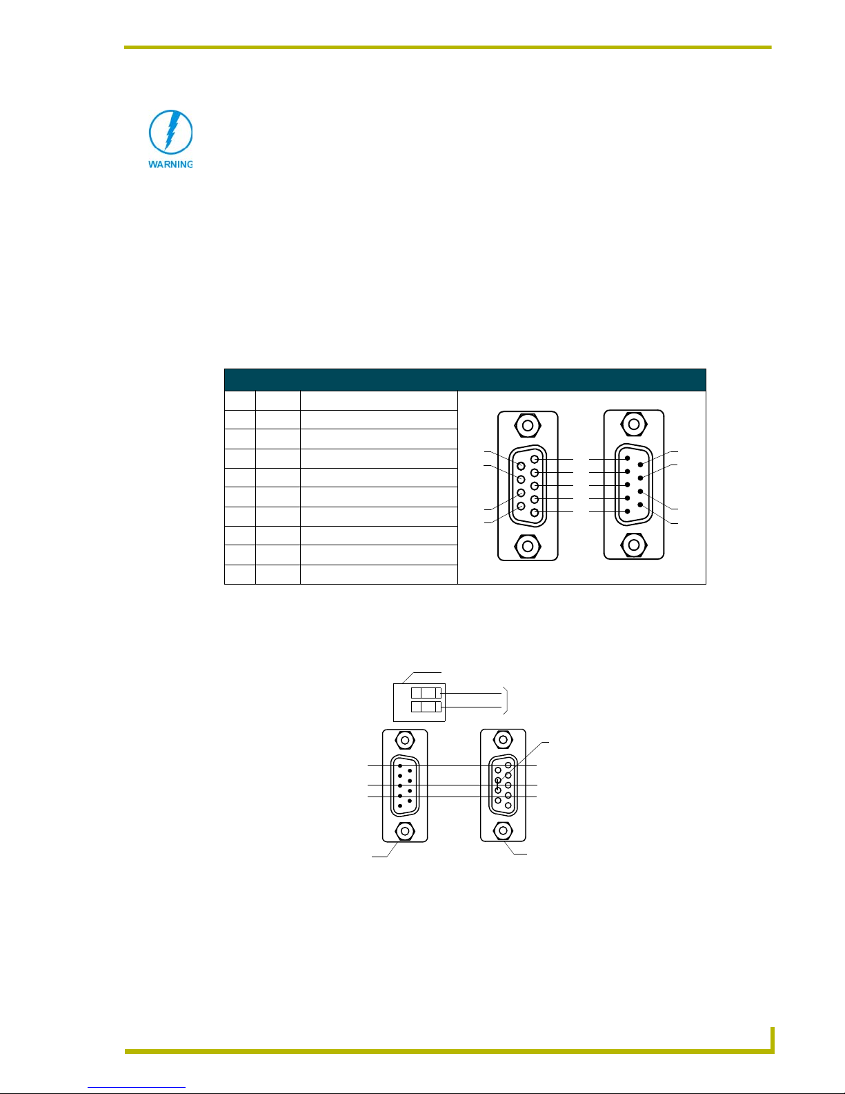
Using the (DB9) RS-232 connector for mouse control or data
The dual-function (DB9) RS-232 connector supports most standard serial mouse control devices
and RS-232 communication protocols for PC data transmission.
The following table lists (DB9) RS-232 connector pinouts and FIG. 9 shows the (DB9) RS-232
connector and power supply wiring diagram.
Use connector pins 2, 3, and 5 for data and ground. For some applications, you may need to strap
pins 7 (request to send) and 8 (clear to send) together, depending on the PC.
Never connect both power wires from the power supply and Central Controller to the
PWR terminal on the touch panel AXlink connector. Only the power supply’s PWR
wire should be connected to the touch panel AXlink connector. If both sources are
used to provide power to the touch panel, an electrical hazard is created and the
threat of both equipment damage and injury is likely.
(DB9) RS-232 Connector Pinouts
Pin Signal Function
1 N/A Not used
2 RXD Receive data
3 TXD Transmit data
4 DTR Data terminal ready (not used)
5 GND Signal ground
6 DSR Data set ready (not used)
7 RTS Request to send (not used)
8 CTS Clear to send (not used)
9 N/A Not used
FIG. 9 DB9 RS-232 connector and power supply wiring diagram
9
8
7
6
5
4
3
2
1
9
8
7
6
Female
Male
Power connector
Mouse or PC, DB9 connector
Female
Male
Touch panel
DB9 connector
Optional 7 to 8-pin
connector
2 (RXD)
3 (TXD)
5 (GND)
2 (RXD)
3 (TXD)
5 (GND)
+ (PWR)
- (GND)
12 VDC power supply
Page 16

Installation
12
10.4" Touch Panels
Using the VGA IN HD-15 (male) high-density connector
Connect the VGA source equipment’s HD-15 (female) connector to the VGA IN HD-15 (male)
high-density connector on the rear panel of the touch panel. The table below lists the VGA IN
HD-15 connector pinouts.
VGA IN HD-15 Connector Pinouts
Pin Signal Function
1 Red Red signals
2 Green Green signals
3 Blue Blue signals
4 N/A Not used
5 GND Signal Ground
6 RAGND Red analog ground
7 GAGND Green analog ground
8 BAGND Blue analog ground
9 N/A Not used
10 SAGND Synchronization analog ground
11 N/A Not used
12 N/A Not used
13 HSYNC Horizontal synchronization signal
14 VSYNC Vertical synchronization signal
15 N/A Not used
VGA HD-15 (male)
connector
10
6
5
1
15
11
CG10 panels are capable of receiving a VGA signal. These VGA signals can be
displayed on a touch panel as a background image and NOT within a video button.
An RGB signal can only be displayed within a Video WIndow Button.
Page 17

Installation
13
10.4" Touch Panels
Page 18

Installation
14
10.4" Touch Panels
Page 19
Designing Touch Panel Pages
15
10.4" Touch Panels
Designing Touch Panel Pages
There are two ways to approach creating touch panel pages:
! TPDesign3 - Refer to the TPDesign3 Touch Panel Program (Version 3. 16 or higher)
Instruction Manual for more information.
! On-board editor
This section describes the basics of using the on-board editor to create pages and buttons. For more
information, refer to the G3 Firmware Design and Reference instruction manual.
Buttons
Standard button types include rectangles and other geometric shapes you can create with the touch
panel editor. Buttons are set with attributes, meaning there is a response from the Central Controller
when you touch the button.
General buttons are part of the default touch panel program and cannot be changed. General buttons
create or revise pages and specify panel communication parameters. Button examples include
selection buttons, information buttons, adjustment buttons, and operation bars. The general button
categories are described in the table below.
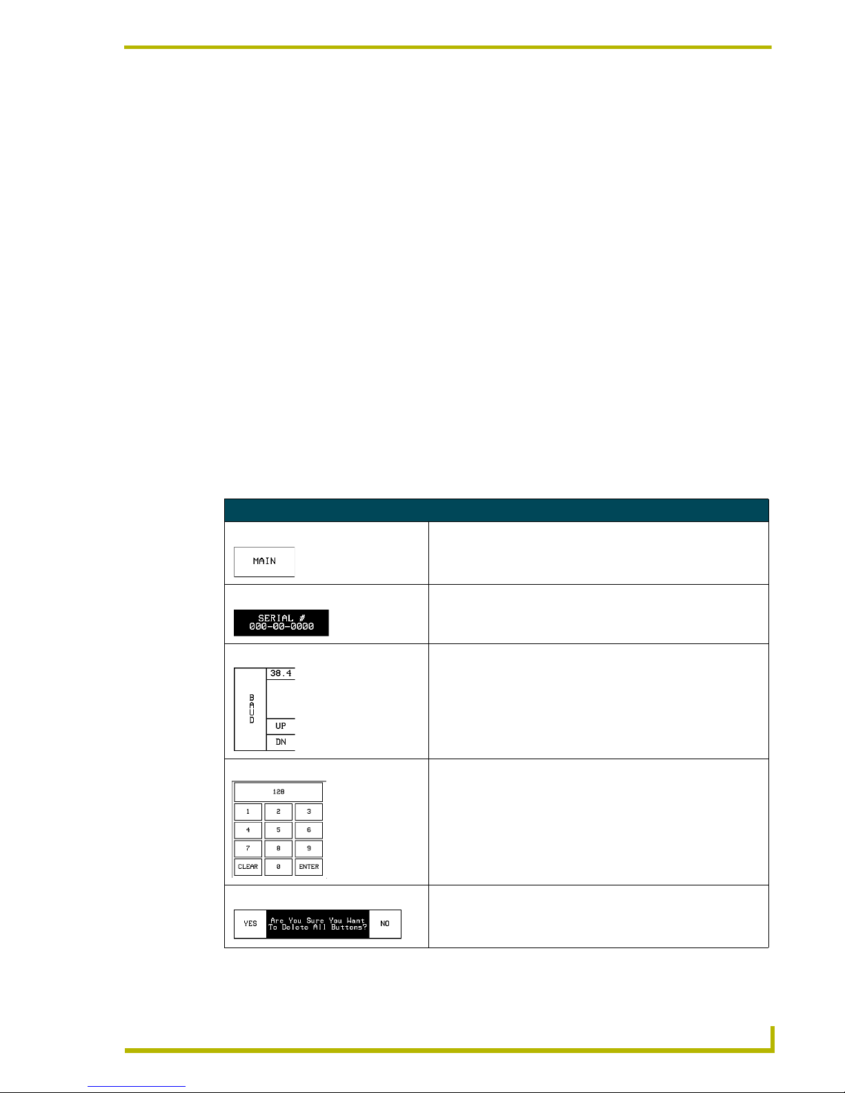
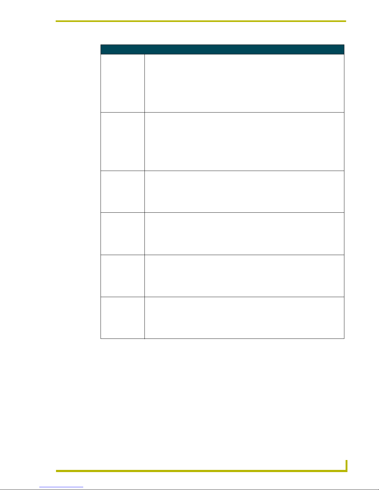
General Button Categories
Selection buttons Selection buttons appear on touch panel pages and set communica-
tion parameters.
Information buttons Information buttons contain serial numbers and firmware version
information. The properties of these buttons cannot be changed.
These buttons have a dark fill and light text.
Adjustment buttons You can use the UP and DN buttons to set adjustment buttons. The
adjustment button example sets the baud rate for the connection
from the touch panel to the computer.
Keypad buttons The keypad button opens a keypad so you can enter a password or
value assignment. All keypad buttons are interactive except for the
entry display.
Decision buttons Decision buttons appear when an operation has two options and
requires verification before an action is performed.
Page 20
Designing Touch Panel Pages
16
10.4" Touch Panels
Activating Edit Mode
Before designing touch panel pages and buttons, you must activate Edit mode. Once activated, use
the
EDIT button to enter Edit mode. This mode has options to add and configure touch panels and
buttons. When powering up the touch panel, the first page is the Main page (see FIG. 10). Note that
the Edit button is not available initially. If you have a pre-programmed panel, you may not see the
Main Page.
To activate edit mode:
1. Press
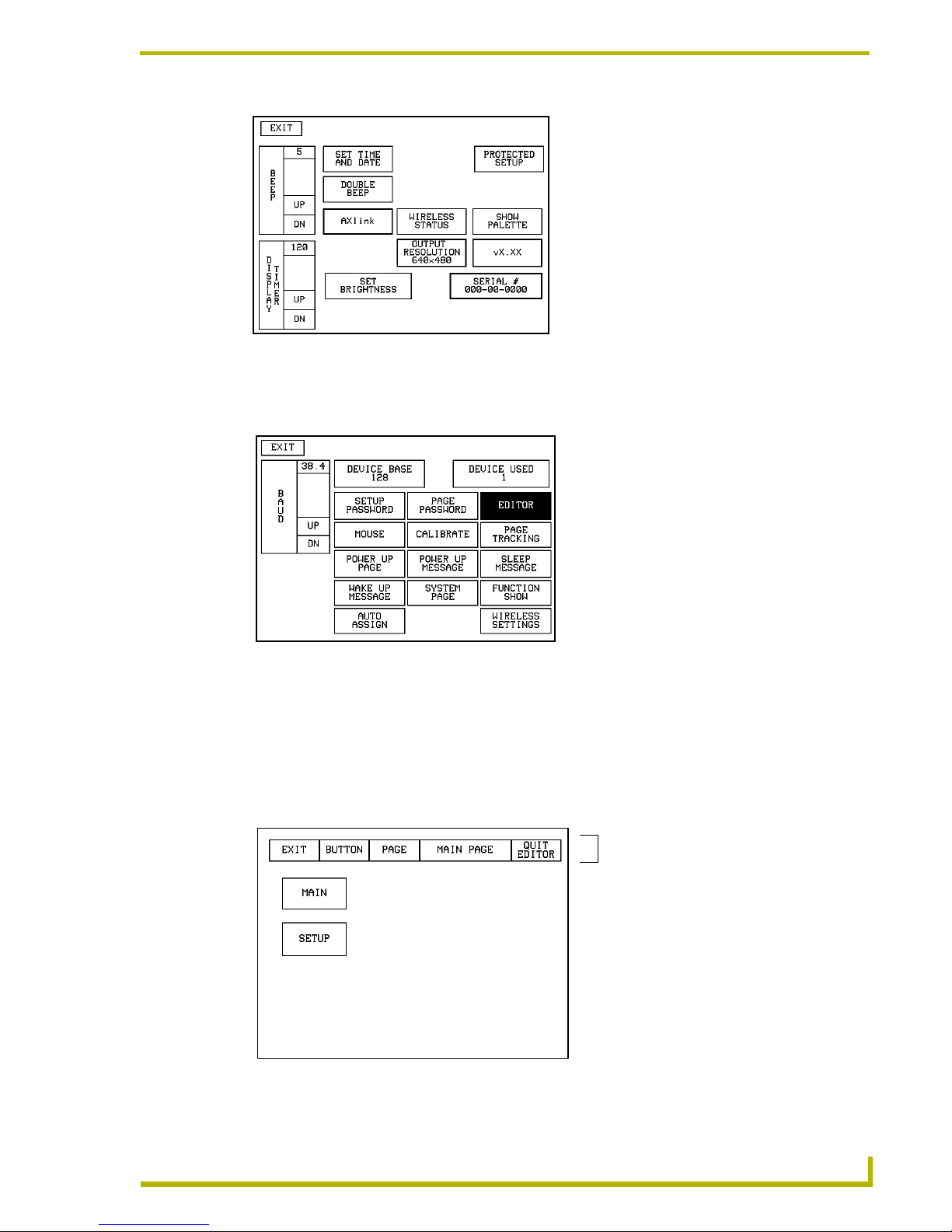
SETUP in the Main page to open the Setup page (FIG. 11).
2. Press
PROTECTED SETUP to open the keypad.
3. Enter 1988 (default password) in the keypad and press
ENTER to open Protected Setup page. If
you press
ENTER after typing an incorrect password, you are immediately returned to the
previous page.
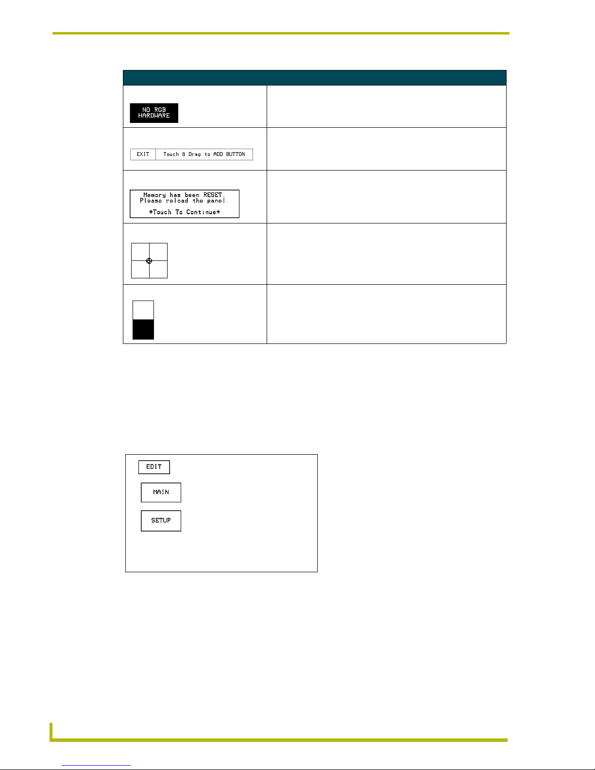
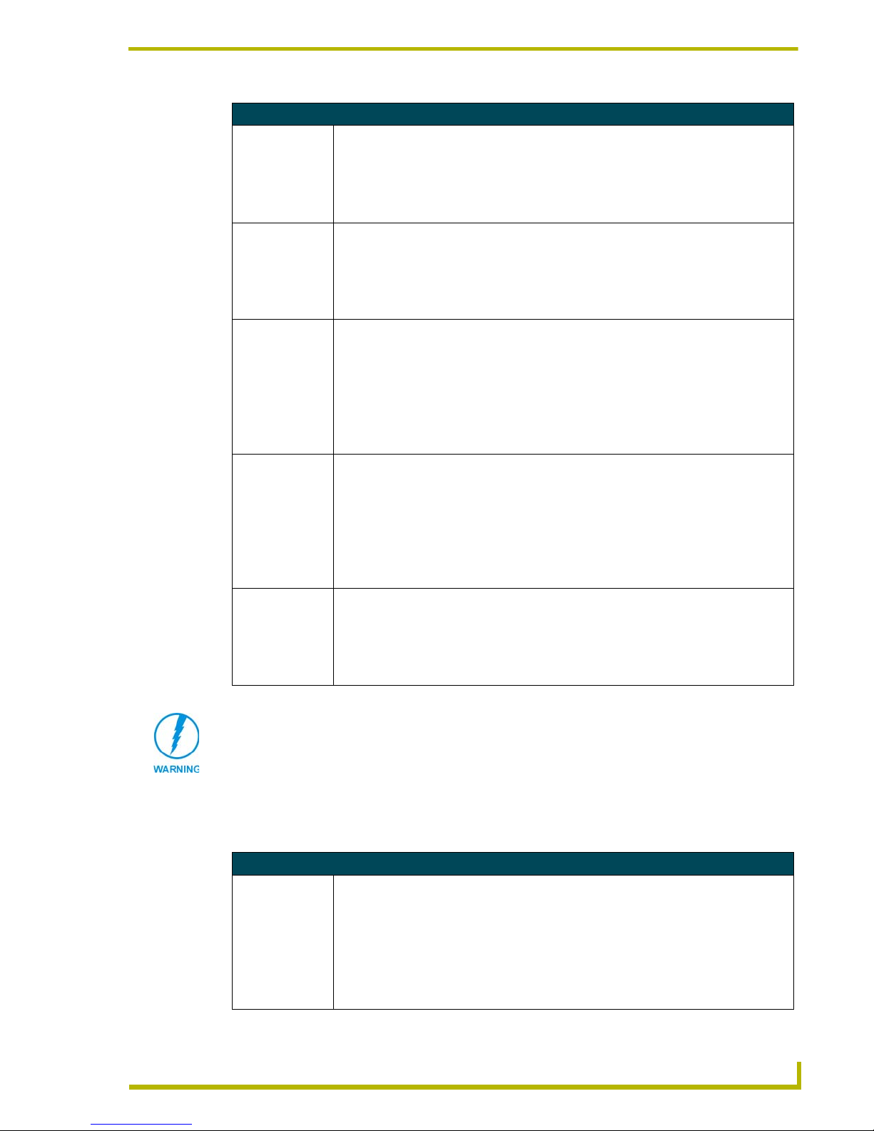
General Button Categories (Cont.)
Status buttons Status buttons always have a dark fill with light letters and have no
functionality except to display information.
Operation bars Operation bars appear in the place of the Editor bar, after selecting a
button or page edit operation. The operation bar indicates which edit
function is currently active. When an edit operation is selected, it
remains active until you press EXIT.
Touch to Continue buttons "Touch to Continue" buttons appear when an operation requires user
acknowledgement.
Joystick buttons Joysticks are vertical and horizontal direction controllers for use with
pan and tilt camera controllers.
Bargraph buttons Bargraph buttons display a dynamic bargraph (vertical or horizontal).
An example is the battery level indicator button.
FIG. 10 Main Page
Page 21
Designing Touch Panel Pages
17
10.4" Touch Panels
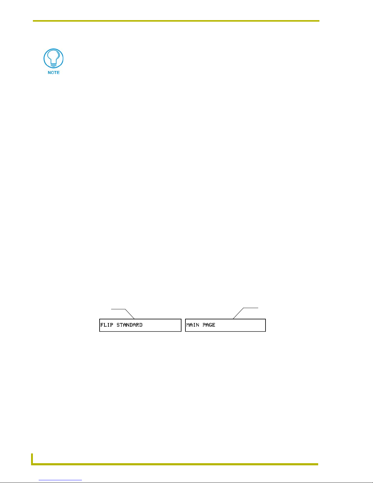
4. Press EDITOR to enable Edit mode. The EDITOR button is highlighted in the Protected Setup
page when enabled, as shown in FIG. 12.
5. Press
EXIT to close the Protected Setup page and return to the Setup page (now in Edit mode).
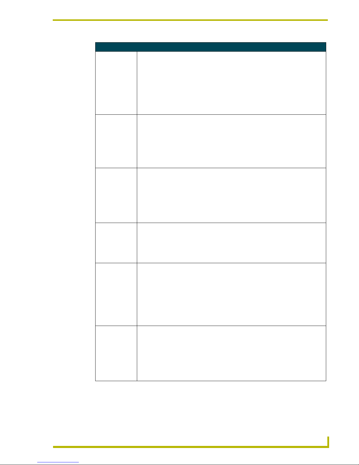
6. Press
EXIT again to return to the Main page. The EDIT button appears at the top of the page
indicating Edit mode is active.
7. Press
EDIT to open the Edit bar. The BUTTON and PAG E options, in the Edit bar (FIG. 13), are
used to design and modify button and page settings.
FIG. 11 Setup page
FIG. 12 Protected Setup page with the active EDITOR button
FIG. 13 Main page with Edit bar
Edit bar
Page 22

Designing Touch Panel Pages
18
10.4" Touch Panels
Setting the Device Base
Press the DEVICE BASE option, in the Protected Setup page (FIG. 12), to assign a base (starting)
device address to the touch panel.
1. Enter the base address for the touch panel. The base address range is from 1 - 255. Standard
device addresses begin at 128.
2. Press
ENTER to save the value.
Setting the Device Used
Use the DEVICE USED option in the Protected Setup page (FIG. 12) to assign a value for the
number of devices being controlled by the touch panel.
1. Press
DEVICE USED to open the keypad and enter the panel’s device number from 1 - 4. Each
device number supports up to 255 programmable channel codes. The multiple device settings
allow you to create up to four unique touch panel buttons and/or pages. This value is used to
determine the current device being used by the panel.
2. Enter the number of devices being used by the touch panel.
3. Press
ENTER to save the value.
Adding a Page
1. Press PAG E on the Edit bar to open the PA GE menu.
2. Press
ADD to open the keyboard and enter a name for the new page. Page names can be up to
20 characters.
3. Press
EXIT CHANGE to save, close the keyboard, and go to the new page.
Setting the page color
1. Press
EDIT to open the Edit bar on the newly created page.
2. Press
PAG E on the Edit bar to open the PAG E menu.
3. Press
PAG E C OL O R to open the color palette.
4. Select a color from the palette; the page automatically changes to the new color.
Adding a Button
To add a button to the current page:
1. Press
BUTTON on the Edit bar to open the BUTTON menu.
2. Press
ADD to open the ADD BUTTON operation bar. On the LCD screen, touch and drag to
create a button. The first touch point is the upper-left corner of the button.
CG10 panels are capable of receiving a VGA signal. These VGA signals can only
be displayed on a touch panel as a background image and NOT within a video
button. From the Edit bar, go to Page > Page Color > VGA Page. This sets the
background color to display the VGA signal.
Refer to the G3 Firmware instruction manual for more detailed information.
Page 23

Designing Touch Panel Pages
19
10.4" Touch Panels
Resizing a button
1. Press
BUTTON on the Edit bar to open the BUTTON menu.
2. Press
RESIZE. Then, touch any edge of the button and drag. Removing your finger from the
panel saves the button dimensions.
Defining On-Screen and External Button Properties
External pushbuttons are configured with features similar to on-screen buttons. Their functionality
can be set just as any other button on the touch panel.
Use the
PROPERTIES option of the BUTTON menu in the Edit bar to set button borders, page flips,
button colors for channel on/off conditions, channel/variable text codes, and string/macro
assignments.
External button properties include only the button type, page flips, channel codes, and string/macro
assignments. Although the Border and Color sections of this page appear, they are of no use to
external pushbuttons since they do not appear on-screen.
To set button properties:
1. Press
BUTTON on the Edit bar to open the BUTTON menu options.
2. Press
PROPERTIES to open the PROPERTIES operation bar.
3. Press the new button to open the Button Properties page. This page lists the properties for the
active button.
4. Press
BUTTON TYPE; this opens the BUTTON TYPE menu.
5. Choose a button type for the selected button to open the associated Button Properties page.
Each button type has its own Button Properties page with settings specific to the button.
6. Press
BORDER to open the BUTTON BORDER pages.
7. Select a border to set for the button and return to the Button Properties page. The
BORDER
button changes to show the selected border type.
Setting the channel code
The channel button sets the device and button channel codes.
1. In the Button Properties page, press
DEV to open the keypad and set the touch panel’s device
number.
2. Enter 1, 2, 3, or 4 in the keypad. The programming software uses device codes 1 - 4 to identify
the touch panel. Refer to the G3 Firmware Design and Reference instruction manual for more
information.
A Video signal can only be displayed within a Video WIndow Button.
From the Edit bar, go to Button > Add. Touch the screen to size the button. Open
Button > Properties and select Video Window from the Button Type section. Refer to
the G3 Firmware instruction manual for more detailed information.
Channel codes and variable text codes work the same for all button types, including
joysticks, and bargraphs.
Page 24
Designing Touch Panel Pages
20
10.4" Touch Panels
3. Press ENTER to save the device number, close the keypad, and return to the Button Properties
page.
4. Press
CHAN to open the keypad and enter a channel value of 1 - 255. The source code uses the
channel code number to identify the button and its programmed operations. The channel code
for non-active buttons is 0.
5. Press
ENTER to save the channel number, close the keypad, and return to the Button Properties
page.
Setting the variable text code
The variable text buttons set the device and button channel codes for the buttons.
1. Press
DEV to open the keypad and set the device number.
2. Enter 1, 2, 3, or 4 in the keypad. The source code uses device codes 1 - 4 to identify the touch
panel.
3. Press
ENTER to save, close the keypad, and return to the Button Properties page.
4. Press
CHAN to open a keypad and set the channel number.
5. Enter a channel value of 1 - 255 in the keypad. The source code uses the channel code number
to identify the button and its operations.
6. Press
ENTER to save the channel number, close the keypad, and return to the Button Properties
page.
Setting the page flip
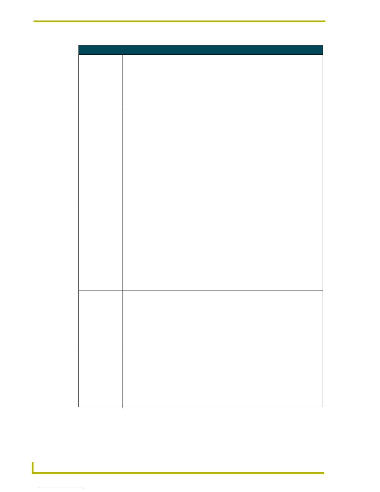
1. Press the
PAG E FL I P TYPE button (FIG. 14) in the Button Properties page to open the PAGE FLIP
T
YPE menu.
2. Select a Page Flip type. If you select
FLIP PREVIOUS in the PAGE FLIP TYPE menu, the FLIP TO
P
AGE button appears.
3. Press the
FLIP TO PAGE button (FIG. 14) to open a list of all the saved touch panel pages. If the
desired page is not present in the menu, check to verify the page has been saved.
4. Select the target page for the page flip.
If DEVICE USED is set to 4 and Base Device Number is 128, the Controller recognizes
bus devices 128 - 131.
The panel will not allow you to enter a device number greater than the DEVICE USED
without first displaying a decision box asking if you accept the new selection or not.
FIG. 14 Page FLIP Type button
Flip to Page button
Page FLIP type
button
Page 25

Designing Touch Panel Pages
21
10.4" Touch Panels
Setting the button colors for channel-off conditions
1. Press any button to open the Button Properties page.
2. Press
BORDER under CHANNEL OFF in the Button Properties page. The color palette appears.
Select a color to set as the border.
3. Press the
FILL button in the Button Properties page to open the palette. Select a color to set as
the fill.
4. Press the
TEXT button to open the palette. Select a color to use for the text.
5. Press
EXIT SAVE CHANGE in the Button Properties page to save the new button properties and
return to the current page.
Adding text, icons, and bitmaps to a button
1. Press
BUTTON on the Edit bar to open the BUTTON menu.
2. Press
TEXT/IMAGE to add text to the button. The TEXT/IMAGE operation bar appears.
3. Press any button to open the Text/Image page.
4. Go through each option and set as desired:
! TEXT OFF and TEXT ON sets the text for the button's Off and On state.
! ICON OFF and ICON ON sets the icon for the button's Off and On state.
! BITMAP OFF and BITMAP ON sets the bitmap for the button's Off and On state.
! MAKE ON SAME AS OFF sets the On and Off properties the same.
5. Press
EXIT SAVE CHANGE to close the Text/Image page and return to the Main page.
Using TPDesign3 to Download Bitmaps, Icons, and Fonts
TPDesign3 allows you to download bitmaps, icons, and fonts into your touch panel from an
existing touch panel program. Touch Panel programs are created in the TPDesign3 software
program. Refer to the TPDesign3 Touch Panel Program instruction manual for more information.
Use the Download to Panel button to download a project file.
To download bitmaps, icons and/or fonts from an existing TPDesign3 project file:
1. Launch the TPDesign3 software program and open a project file that contains the desired
bitmaps, icons, and fonts.
2. Select File from the menu bar to open the File menu.
3. In the File menu, click on Download to Panel, this opens the Download to Panel dialog box.
4. Click on the Comm Settings tab to set the communications port, baud rate, and other
communication settings.
5. Then, click the Actions tab to set the communication mode and select which elements of the
project file you want to download to the touch panel.
You cannot create or edit buttons with Unicode fonts on the panel. Any use of the
TEXT/IMAGE button to alter or create Unicode font supported buttons must be done
in the TPDesign3 Touch Panel Design Program.
Page 26

Designing Touch Panel Pages
22
10.4" Touch Panels
6. In the What To Send area, select one or more of the available options (All Bitmaps, All Icons,
All Fonts).
7. Select the mode of communication with the touch panel (RS-232 and AXlink). Confirm that
the correct panel is selected by verifying the ID values with the Base Address assigned to the
touch panel in the Protected Setup page.
8. After clicking Connect, the Available Panels list appears in the Available Panels field. Click
Begin to start downloading the project file into the panel.
9. After completing the download, the bitmaps, icons and fonts that were downloaded are now
accessible via the BITMAPS, ICONS and FONTS menus.
Creating a Bargraph and Joystick
Bargraphs are level monitors and adjustable level controls. These levels can be configured to
monitor and adjust audio outputs and lighting levels.
Joysticks are vertical and horizontal direction controllers you can use for camera for pan and tilt
control. Before starting, make sure to connect the touch panel to your Controller; otherwise, the
joystick will not work properly.
Adding a bargraph or joystick button
Create a new button using the Add operation bar in the
BUTTON menu.
1. Press
BUTTON in the Edit bar to open the BUTTON menu.
2. Press
PROPERTIES in the BUTTON menu to open the PROPERTIES operation bar.
3. Press any button to open the Button Properties page.
4. Press
BUTTON TYPE to open the BUTTON TYPE menus. Choose a button type to open its
Button Properties page.
Setting Bargraph and Joystick Properties
Use the Button Properties page to set channel, level, and button colors. Refer to the Setting the
variable text code section on page 20 and the Setting the channel code section on page 19 for
further information. Refer to the Setting the button colors for channel-off conditions section on
page 21 for more information on colors for channel-off conditions.
Setting the level code
Level buttons set the device and number codes for the touch panel.
1. Press
DEV to open a keypad and set the device number.
2. Enter 1, 2, 3, or 4 in the keypad. The programming software uses device codes
1 - 4 to identify the touch panel.
3. Press
ENTER to save the level device number, close the keypad, and return to the Button
Properties page.
Joysticks use two level numbers. The first is for the X-axis and the second for the Yaxis. You only need to specify the first level.
Page 27

Designing Touch Panel Pages
23
10.4" Touch Panels
4. Press NUM to open a keypad and set the level number assigned to the device.
5. Enter a number 1 – 8. Each device can have from 1 – 8 levels except joysticks, where the range
is 1 – 7.
6. Press
ENTER to save, close the keypad, and return to the Button Properties page.
Page 28

Designing Touch Panel Pages
24
10.4" Touch Panels
Page 29

Programming
25
10.4" Touch Panels
Programming
You can program the touch panel to perform a wide variety of operations using AXCESS
Send_Commands and variable text commands. Use the commands described in this section to
program the touch panel. Refer to the AXCESS Programming Language instruction manual for
complete information.
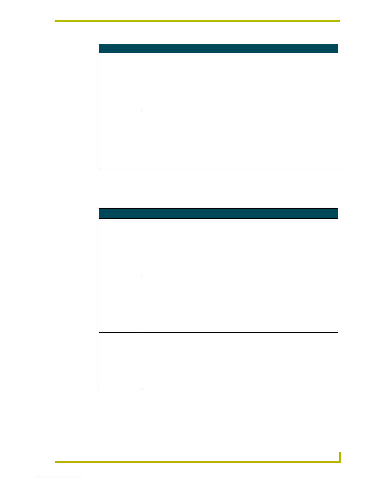
Serial Commands
Serial Commands are used in the AxcessX Terminal Emulator Mode. These commands are case
insensitive.
Serial Commands
?PAR
Returns panel
parameters to the
PC terminal.
Panel parameters include: firmware version, device number, mouse type, output resolution, number of devices, cursor enable, brightness, and contrast (always=0).
Syntax:
"?PAR"
Example:
?PAR
Requests the information.
$SC
Sends a serial
port
send_command
within a panel, as
if sent from
Axcess.
Syntax:
"$SC <device offset>,"’<send_command>,<variable
text #>,<data>’""
Var iables :
device offset = Device number
variable text # = The variable text number value on the touch panel.
Example:
$SC 1,"’@TXT’,2,’TEXT’"
The string is sends the command to put text on a button with a variable text value of 2. It is
crucial that all the correct ’ and " be used with no spaces after the commas.
Example:
$SC 1,"’SLEEP’"
Sets a touch panel to sleep.
CALIBRATE
Starts touch panel
calibration.
Syntax:
"CALIBRATE"
Example:
CALIBRATE
Starts the calibration sequence mode on the touch panel.
CHECK CAL
Enters the calibration test mode.
Syntax:
"CHECK CAL"
Example:
CHECK CAL
Begins the calibration check mode on the touch panel.
Page 30

Programming
26
10.4" Touch Panels
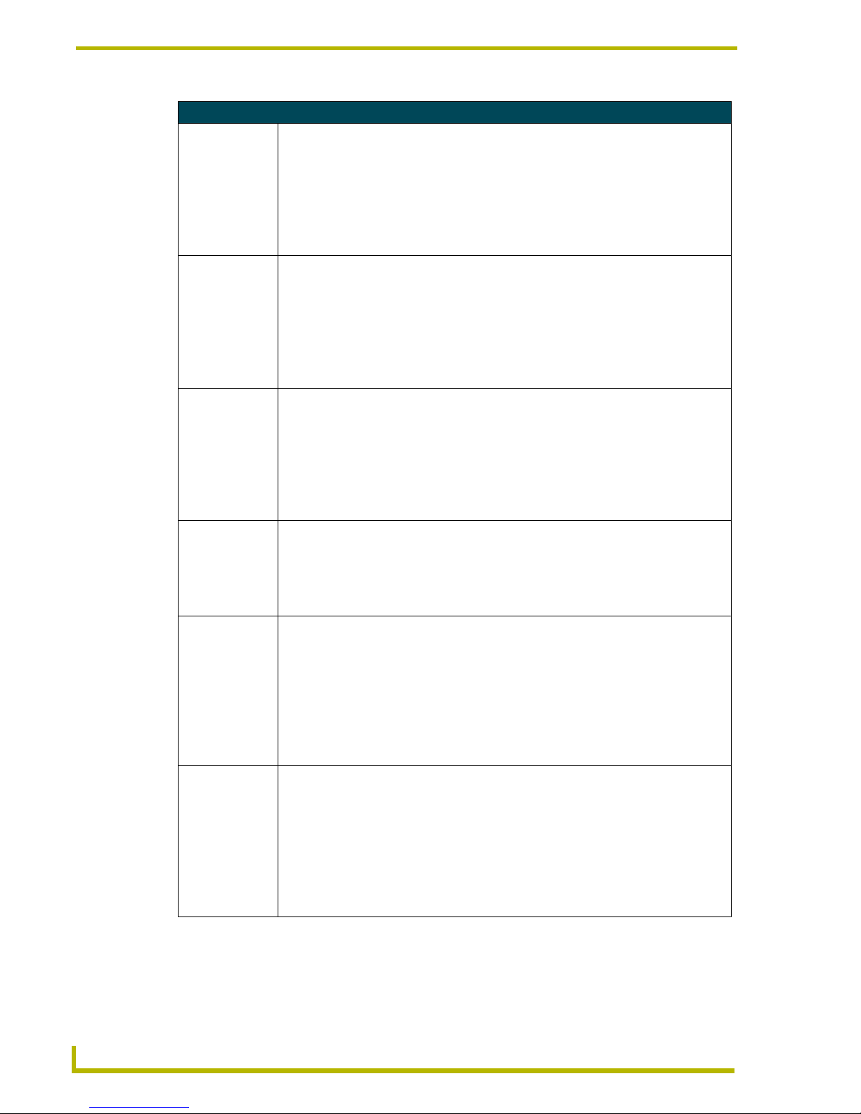
Serial Commands (Cont.)
ECHO ON
Turns On character echo.
Syntax:
"ECHO ON"
Example:
ECHO ON
The character echo is sent back to the computer.
ECHO OFF
Turns Off character echo.
Syntax:
"ECHO OFF"
Example:
ECHO OFF
The character echo is not sent back to the computer.
GET CAL
Gets the calibration variables.
Syntax:
"GET CAL"
Example:
GET CAL
Gets the calibration variables on the touch panel.
HELLO
Verifies that serial
communication is
working properly.
Syntax:
"HELLO"
Example:
HELLO
If the communication is active and working, the response is "How are you doing?".
MOUSE
Sets the serial
interface type.
Syntax:
MOUSE <mouse type>
Var iables :
mouse type =
00: Mouse cursor Off
01: Microsoft
®
serial mouse/cursor On
8000: Touch Output to Serial Port 8000 (Elo IntelliTouch)
Example:
MOUSE 01
Turns on Microsoft® compatible serial mouse. Refer to the @MOU section on page 40 for
the chart describing the BIT information and definitions.
RESET
Cycles power on
the touch panel.
Syntax:
"RESET"
Example:
RESET
Cycles the power on the touch panel. Once the firmware is downloaded, send this command to recycle power to the panel. This command prevents the user from having to physically re-cycling power on the unit.
Page 31

Programming
27
10.4" Touch Panels
Serial Commands (Cont.)
SET CAL
Sets the calibration variables.
Syntax:
“SET CAL <X Multiplier> <X Offset> <Y Multiplier> <Y
Offset>"
Example:
SET CAL 2F 3A 2B 62
Sets the calibration values on the touch panel.
SETUP
Puts the touch
panel on the
Setup Page.
Syntax:
"SETUP"
Example:
SETUP
Flips the touch panel to the Setup page.
VER
Restores the current version.
Syntax:
"VER"
Example:
VER
Returns the current version of the main firmware.
WORKING?
Verifies the communication
between the touch
panel and the Terminal Emulator.
Syntax:
"WORKING?"
Example:
WORKING?
Response:
$SC 1,"’CPAGE72-Main Page’"
Responding touch panel turns its Main page the color white. This command verifies serial
communication. The 10.4" panel must have a page named Main Page for this command to
work properly.
ZAP!
Clears all memory.
Syntax:
"ZAP!"
Example:
ZAP!
Clears all memory and erases all buttons, pages, drawings, and symbols.
Only use the ZAP! command to erase the saved data in the touch panel; data cannot be
recovered after it is erased.
Page 32

Programming
28
10.4" Touch Panels
System Send_Commands
System Send_Commands are stored in the Controller and direct the touch panel to perform various
operations.
System Send_Commands
$SP
Sends data out
the serial port with
trailing CR and LF.
Translates the ¦ and translates it as a carriage return to the next line.
Syntax:
"’$SP "<data>"’"
Example:
SEND_COMMAND TP,"’$SP "CALIBRATE"’"
Sends the Calibrate command to another panel through the Serial Port. It is crucial that all
the correct ’ and " be used with no spaces after the commas.
ABEEP
Outputs one panel
beep even if the
beep value is set
to 0 in the Setup
page.
Syntax:
"’ABEEP’"
Example:
SEND_COMMAND TP,"’ABEEP’"
Beeps the panel.
ADBEEP
Outputs a double
beep even if the
double beep value
is set to 0 in the
Setup page.
Syntax:
"’ADBEEP’"
Example:
SEND_COMMAND TP,"’ADBEEP’"
Double beeps the panel.
AKEYB
Opens the touch
panel keyboard
and initializes the
text string entry.
The keyboard string is set to null during power-up and stored until power-down.
Syntax:
"’AKEYB-<text string>’"
Var iable:
text string = 0 - 59 characters
Example:
SEND_COMMAND TP,"’AKEYB-TOUCH HERE’"
Opens the touch panel keyboard with TOUCH HERE in the display.
AKEYP
Opens the touch
panel keypad and
initializes the
number string
entry.
The keyboard string is set to null during power-up and stored until power-down.
Syntax:
"’AKEYP-<number string>’"
Var iable:
number string = 0 - 9999
Example:
SEND_COMMAND TP,"’AKEYP-1988’"
Opens the touch panel keypad with 1988 in the display.
AKEYR
Closes/opens the
touch panel keyboard/pad.
Syntax:
"’AKEYR’"
Example:
SEND_COMMAND TP,"’AKEYR’"
Closes the keyboard/keypad opened using the ’AKEYB’, ’AKEYP’, or ’PKEYP’
commands.
Page 33
Programming
29
10.4" Touch Panels
System Send_Commands (Cont.)
BAUD
Sets the program
port baud rate.
The baud rate can also be set in the Protected Setup page’s BAUD level indicator.
Syntax:
"’BAUD <baud rate>’"
Var iable:
baud rate = 38400, 19200, 9600, 4800, 2400, 1200, 600, and 300
Example:
SEND_COMMAND TP,"’BAUD 38400’"
Sets the Baud rate to 38400.
BEEP
Gives an output of
one beep.
This beep command sounds one tone for a time length of 50 milliseconds.
Syntax:
"’BEEP’"
Example:
SEND_COMMAND TP,"’BEEP’"
Activates one beep tone. Beeps the panel if the Beep button is not set to 0. The BEEP
command does not disable the beep after a QBEEP command.
BRIT
Adjusts brightness
of display.
Syntax:
"’BRIT-<level>’"
Var iable:
level = 1 - 8 (1 = minimum; 8 = maximum)
Example:
SEND_COMMAND TP,"’BRIT-8’"
Sets to highest brightness level.
CALIBRATE
Starts the touch
panel calibration
sequence.
Syntax:
"’CALIBRATE’"
Example:
SEND_COMMAND TP,"’CALIBRATE’"
Starts the calibration operation on the touch panel.
CLOCK
Sets the time and
date.
Syntax:
"’CLOCK <mm-dd-yy> <hh:mm:ss>’"
Var iables :
mm = 01 - 12, dd = 01 - 31, yy = 00 - 99
hh = 00 - 23, mm = 00 - 59, ss = 00 - 59
Example:
SEND_COMMAND TP,"’CLOCK 02-08-98 19:16:00’"
Sets the touch panel’s date to February 8, 1998, and time to 7:16 p.m.
CURSOR
Turns the cursor
display On or Off if
the touch device
has a cursor.
Syntax:
"’CURSOR <OFF/ON>’"
Var iables :
Off = 0 and On = 1
Example:
SEND_COMMAND TP,"’CURSOR 0’"
Turns the cursor display Off.
Page 34
Programming
30
10.4" Touch Panels
System Send_Commands (Cont.)
DBEEP
Gives a double
beep output.
This command only works if the Double Beep value in the Protected Setup page is set to
On.
Syntax:
"’DBEEP’"
Example:
SEND_COMMAND TP,"’DBEEP’"
Double beeps the panel.
ILEV
Inverts the joystick
axis.
Syntax:
"’ILEV <joystick axis to invert>’"
Var iables :
joystick axis to invert =
0 : Normal G3 joystick (origin: top left)
1 : Invert horizontal axis (origin: top right)
2 : Invert vertical axis (origin: bottom left)
3 : Invert both axes (origin: bottom right)
Example:
SEND_COMMAND TP,"’ILEV 3’"
Inverts the joystick axis to move the origin to another corner.
MOUSE
Turns on the
Microsoft Serial
Mouse.
Syntax:
MOUSE <mouse type>
Var iables :
mouse type =
00: Mouse cursor Off
01: Microsoft
®
serial mouse/cursor On
8000: Touch Output to Serial Port 8000 (Elo IntelliTouch)
Example:
SEND_COMMAND TP,"’MOUSE 01’"
Turns on Microsoft® compatible serial mouse. Refer to the @MOU section on page 40 for
the chart describing the BIT information and definitions.
PAG E
Flips to a page
with a specified
page name.
Syntax:
"’PAGE-<page name>’"
Var iable:
page name = 1 - 50 ASCII characters
Example:
SEND_COMMAND TP,"’PAGE-MAIN PAGE’"
Flips the touch panel to the page named MAIN PAGE.
PKEYP
Displays asterisks (*) for keypad
entries.
Syntax:
"’PKEYP-<number string>’"
Var iable:
number string = 0 - 9999
Example:
SEND_COMMAND TP,"’PKEYP-1988’"
Displays the touch panel keypad with **** instead of 1988.
Page 35
Programming
31
10.4" Touch Panels
System Send_Commands (Cont.)
PPOF
Closes a specific
popup page.
Syntax:
"’PPOF-<page name>’"
Var iable:
page name = 1 - 50 ASCII characters
Example:
SEND_COMMAND TP,"’PPOF-Popup Page 1’"
Closes Popup Page 1.
PPON
Opens a specific
popup page.
Syntax:
"’PPON-<page name>’"
Var iable:
page name = 1 - 50 ASCII characters
Example:
SEND_COMMAND TP,"’PPON-Popup Page 1’"
Opens Popup Page 1.
QBEEP
Stops all beeps.
Syntax:
"’QBEEP’"
Example:
SEND_COMMAND TP,"’QBEEP’"
Stops all beeps, including "’ABEEP’", "’ADBEEP’", and AXlink beeps.
RESET
Clears panel status (same as
power up).
Saved data is not
cleared.
Syntax:
"’RESET’"
Example:
SEND_COMMAND TP,"’RESET’"
Resets the touch panel.
SETUP
Goes to the Setup
page.
Syntax:
"’SETUP’"
Example:
SEND_COMMAND TP,"’SETUP’"
Flips the touch panel to the Setup page.
SLEEP
Forces the touch
panel to screen
saver mode.
Syntax:
"’SLEEP’"
Example:
SEND_COMMAND TP,"’SLEEP’"
Activates the screen saver mode on the touch panel.
Page 36

Programming
32
10.4" Touch Panels
System Send_Commands (Cont.)
TPAGEON
Activates page
tracking.
Syntax:
"’TPAGEON’"
Example:
SEND_COMMAND TP,’TPAGEON’
DEFINE_DEVICE
TP1 = 128 (*AMX Touch Panel*)
TP2 = 129 (*AMX Touch Panel*)
DEFINE_VARIABLE
TP1_BUFFER[100] (*Buffer for TP1*)
TP2_BUFFER[100] (*Buffer for TP2*)
TRASH[50] (*For Parsing Above*)
DEFINE_START
CREATE_BUFFER TP1,TP1_BUFFER
CREATE_BUFFER TP2,TP2_BUFFER
SEND_COMMAND TP1,'TPAGEON'
SEND_COMMAND TP2,'TPAGEON'
DEFINE_PROGRAM
(* PAGE TRACKING ROUTINE *)
IF(LENGTH_STRING(TP1_BUFFER))
{
IF(FIND_STRING(TP1_BUFFER,'PAGE-',1))
{
TRASH=REMOVE_STRING(TP1_BUFFER,'PAGE-',1)
SEND_COMMAND TP2,"'PAGE-',TP1_BUFFER"
CLEAR_BUFFER TP1_BUFFER
}
IF((FIND_STRING(TP1_BUFFER,'PPON-',1))
OR(FIND_STRING(TP1_BUFFER, 'PPOF-',1)))
{
SEND_COMMAND TP2,TP1_BUFFER
CLEAR_BUFFER TP1_BUFFER
}
}
IF(LENGTH_STRING(TP2_BUFFER))
{
IF(FIND_STRING(TP2_BUFFER,'PAGE-',1))
{
TRASH=REMOVE_STRING(TP2_BUFFER,'PAGE-',1)
SEND_COMMAND TP1,"'PAGE-',TP2_BUFFER"
CLEAR_BUFFER TP2_BUFFER
}
IF((FIND_STRING(TP1_BUFFER,'PPON-',1)) OR
(FIND_STRING(TP1_BUFFER,'PPOF-',1)))
{
SEND_COMMAND TP1,TP2_BUFFER
CLEAR_BUFFER TP2_BUFFER
}
}
(* The command string is sent to the Controller in the ’PAGE-(page name)’ or ’PPON/
PPOF-(page name)’ format. The string is captured in the buffer for one panel and sent to
the other panel. If panels are combined using the DEFINE_COMBINE statement, the routine needs to be written only once, and the command is sent back to the same panel. *)
(* END OF PAGE TRACKING ROUTINE *)
Page 37
Programming
33
10.4" Touch Panels
Video Send_Commands
Video Send_Commands direct the touch panel to perform various video specific operations.
System Send_Commands (Cont.)
TPAGEOFF
Deactivates page
tracking.
Syntax:
"’TPAGEOFF’"
Example:
SEND_COMMAND TP,"’TPAGEOFF’"
Deactivates the page tracking option.
WAKE
Deactivates
screen-saver
mode and resets
the sleep timer.
Syntax:
"’WAKE’"
Example:
SEND_COMMAND TP,"’WAKE’"
Deactivates the touch panel screen-saver mode and resets the sleep timer.
XMRT
Sets the new network communication retry value for
the panel and
SoftROM.
Syntax:
"’XMRT <number>’"
Var iable:
number = 1 - 15 ASCII characters
Example:
SEND_COMMAND TP,"’XMRT 9’"
Sets the XMODEM wait for character retries to 9.
XMTO
Sets the new network communication delay for the
panel and SoftROM.
Syntax:
"’XMTO <number>’"
Var iable:
number = 4 - 30 ASCII characters
Example:
SEND_COMMAND TP,"’XMTO 5’"
Sets the new XMODEM character delay time to 5 seconds.
ZAP!
Clears all memory; erases buttons, pages,
drawings, and
symbols.
Syntax:
"’ZAP!’"
Example:
SEND_COMMAND TP,"’ZAP!’"
Clears all memory and erases all buttons, pages, drawings, and symbols.
Only use the ZAP! command to erase all the saved data in the touch panel; data cannot be
recovered after it is erased.
Video Send_Commands
@VBR
Sets the video signal brightness.
Syntax:
"’@VBR <ASCII setting for Brightness>’"
Var iables :
ASCII brightness setting = 0 (min) - 255 (max)
Example:
SEND_COMMAND TP,"’@VBR 128’"
Sets the video brightness to 128.
Page 38

Programming
34
10.4" Touch Panels
Video Send_Commands (Cont.)
@VBW
Sets the video to
black/white or
color.
Syntax:
"’@VBW <ASCII setting for Black/White input>’"
Var iables :
Black/White input setting = 0: Color
1: Black and White
Example:
SEND_COMMAND TP,"’@VBW 1’"
Sets the video output to black and white.
@VCT
Sets the video
contrast.
Syntax:
"’@VCT <ASCII setting for Contrast>’"
Var iables :
ASCII contrast setting = 0 (min) - 255 (max)
Example:
SEND_COMMAND TP,"’@VCT 128’"
Sets the video contrast to 128.
@VDD
Sets the video
setting for autodetection or manual detection of
the video standard.
Syntax:
"’@VDD <ASCII settings for video detection>’"
Var iables :
ASCII detection settings = 1: Auto-detect video input
2: Manual set NTSC
3: Manual set PAL
4: Manual set SECAM
Example:
SEND_COMMAND TP,"’@VDD 3’"
Detects only PAL.
@VFF
Video Fast Forward Mode Alogrithm.
The algorithm creates independent vertical sync 60 Hz/50 Hz (NTSC/PAL or SECAM) timing, ignoring the sync from the VCR. During fast forward on many VCRs, the vertical sync
timing increases by 8 Hz, thus, causing the video pictures to freeze on our digital hardware.
Syntax:
"’@VFF <ASCII video fast forward settings>’"
Var iables :
ASCII video settings = 0: Normal
1: On
2: Off (required for Tanberg’s non-interlacing equipment)
Example:
SEND_COMMAND TP,"’@VFF 2"
Turns the algorithm Off.
@VHU
Sets video hue.
Syntax:
"’@VHU <ASCII setting for Hue>’"
Var iables :
ASCII hue setting = 0 (min) - 255 (max)
Example:
SEND_COMMAND TP,"’@VHU 128’"
Sets video hue to 128.
Page 39
Programming
35
10.4" Touch Panels
VGA Send_Commands
VGA Send_Commands are stored in the Controller and direct the touch panel to perform various
VGA operations.
Video Send_Commands (Cont.)
@VSD
Resets video
default settings.
Resets the following video attributes to their default settings:
Brightness, Contrast, Saturation, Hue, Interlace
Syntax:
"’@VSD’"
Example:
SEND_COMMAND TP,"’@VSD’"
Resets the video defaults.
@VST
Sets the video
saturation.
Syntax:
"’@VST <ASCII setting for Saturation>’"
Var iables :
ASCII saturation setting = 0 (min) - 255 (max)
Example:
SEND_COMMAND TP,"’@VST 128’"
Sets video saturation to 128.
VGA Send_Commands
VGBC
Sets the blue VGA
signal intensity
(brightness).
Syntax:
"’VGBC-<ASCII setting for blue intensity>’"
Var iable:
ASCII blue intensity setting = 0 - 67
Example:
SEND_COMMAND TP,"’VGBC-67’"
Sets the blue VGA signal intensity to 67 (maximum).
VGCK
Sets the VGA
sherpness.
Syntax:
"’VGCK-<ASCII setting for sharpness>’"
Var iable:
ASCII red intensity setting = 0 - 255
Example:
SEND_COMMAND TP,"’VGCK-255’"
Sets the VGA sharpness to 255 (maximum).
VGCP
Sets the VGA signal sampling to
optimize the picture quality.
Syntax:
"’VGCP-<ASCII setting for signal sampling>’"
Var iable:
AXCII signal sampling setting = 0 - 31
Example:
SEND_COMMAND TP,"’VGCP-31’"
Sets the VGA signal sampling to 31.
Page 40
Programming
36
10.4" Touch Panels
VGA Send_Commands (Cont.)
VGGC
Sets the green
VGA signal intensity (brightness).
Syntax:
"’VGGC-<ASCII setting for green intensity>’"
Var iable:
ASCII green intensity setting = 0 - 67
Example:
SEND_COMMAND TP,"’VGGC-0’"
Sets the green VGA signal intensity to 0 (minimum).
VGHP
Moves the VGA
display horizontally to the right or
left.
Syntax:
"’VGHP-<ASCII setting right or left horizontal position>’"
Var iable:
ASCII horizontal position setting = 0 - 31
Examples:
SEND_COMMAND TP,"’VGHP-15’"
Centers the VGA display horizontally.
VGRC
Sets the red VGA
signal intensity
(brightness).
Syntax:
"’VGRC-<ASCII setting for red intensity>’"
Var iable:
ASCII red intensity setting = 0 - 67
Example:
SEND_COMMAND TP,"’VGRC-0’"
Sets the red VGA signal intensity to 0 (minimum).
VGSD
Resets default
settings of colors,
position, and
tracking.
Syntax:
"’VGSD’"
Example:
SEND_COMMAND TP,"’VGSD’"
Resets VGA defaults.
VGST
Sets the VGA
Synchronization
Threshold value.
Syntax:
"’VGST - <ASCII setting for VGA threshold>’"
Var iable:
ASCII setting: 0 = Analog
1 = TTL
Example:
SEND_COMMAND TP,"’VGST-0’"
Sets the VGA threshold to Analog.
VGSZ
Sets the VGA
Synchronization
Impedence value.
Syntax:
"’VGSZ - <ASCII setting for VGA imepedence>’"
Var iable:
ASCII setting: 0 = 330 Ohms
1 = 75 Ohms
Example:
SEND_COMMAND TP,"’VGSZ-0’"
Sets the VGA impedence to 330 Ohms.
Page 41
Programming
37
10.4" Touch Panels
Programming Numbers
The following information provides the programming numbers for colors, fonts, and borders
Colors can be used to set the colors on buttons, sliders, gauges, and pages. The lowest color number
represents the lightest color-specific display; the highest number represents the darkest display. For
example, 0 represents light red, and 5 is dark red.
Font styles can be used to program the text fonts on buttons, sliders, gauges, and pages. The
programming numbers are assigned consecutively when downloaded to the touch panel.
VGA Send_Commands (Cont.)
VGVP
Moves the VGA
display vertically
up or down.
Syntax:
"’VGVP-<ASCII setting for vertical position>’"
Var iable:
ASCII vertical position setting = 0 - 15
Examples:
SEND_COMMAND TP,"’VGVP-10’"
Centers the VGA display vertically.
Colors and Programming Numbers
Color No. Color No.
Red 0 - 5 Purple 54 - 59
Orange 6 - 11 Magenta 60 - 65
Yellow 12 - 17 Pink 66 - 71
Lime 18 - 23 White 72 - 77
Green 24 - 29 Light Gray 78 - 83
Aqua 30 - 35 Dark Gray 84 - 86
Cyan 36 - 41 Black 87
Royal 42 - 47 Transparent 255
Blue 48 - 53
Font Styles and Programming Numbers
No. Font styles No. Font styles
1 Extra small 5 Extra large
2 Small 6 Hollow medium
3 Medium 8 Hollow extra large
4 Large 32 - 255 Variable fonts
You must import variable text fonts into a TPDesign3 project file, and download the
project file containing the fonts to the touch panel. The variable fonts are
programming numbers assigned by the touch panel during the download process.
Page 42

Programming
38
10.4" Touch Panels
Border styles can be used to program borders on buttons, sliders, and gauges.
Shorthand Send_Commands
The table below lists the shorthand Send_Commands you can use with touch panels. The shorthand
command data is 1-byte, non-ASCII format except for pages, passwords, text, and bitmap names.
Border Styles and Programming Numbers
No. Border styles No. Border styles
0 No border 11 Double shadow
1 No border special 20 3-dimensional rectangle 1
2 Single line 21 3-dimensional rectangle 2
3 Double line 22 3-dimensional round 1
4 Triple line 23 3-dimensional round 2
5 Single rounded 24 3-dimensional neon 1
6 Double rounded 25 3-dimensional neon 2
7 Single raised 26 3-dimensional neon blue
8 Double raised 27 3-dimensional neon green
9 Triple raised 40 Single diamond
10 Double-line two single 41 Double diamond
Shorthand Send_Commands
@CBF
Sets the OFF
feedback border
color to the specified color.
This works only if the specified background color is not the same as the current color.
Syntax:
"’@CBF’,<variable text address>,<color_number>"
Var iables :
variable text address = 1 - 255
color number = See the Colors and Programming Numbers table on page 37.
Example:
SEND_COMMAND TP,"’@CBF’,1,0"
Sets the OFF feedback border color to Red for the variable text button 1.
@CBN
Sets the ON feedback border color
to the specified
color.
This works only if the specified background color is not the same as the current color.
Syntax:
"’@CBN’,<variable text address>,<color_number>
Var iables :
variable text address = 1 - 255
color number = See the Colors and Programming Numbers table on page 37.
Example:
SEND_COMMAND TP,"’@CBN’,2,78"
Sets the ON feedback border color to Gray for variable text button 2.
Page 43

Programming
39
10.4" Touch Panels
Shorthand Send_Commands (Cont.)
@CFF
Sets the OFF
feedback fill color
to the specified
color.
This only works if the specified background color is not the same as the current color.
Syntax:
"’@CFF’,<variable text address>,<color_number>"
Var iables :
variable text address = 1 - 255
color number = See the Colors and Programming Numbers table on page 37.
Example:
SEND_COMMAND TP,"’@CFF’,1,72"
Sets the OFF feedback fill color to White for variable text button 1.
@CFN
Sets the ON feedback fill color to
the specified
color.
This only works if the specified background color is not the same as the current color.
Syntax:
"’@CFN’,<variable text address>,<color_number>"
Var iables :
variable text address = 1 - 255
color number = See the Colors and Programming Numbers table on page 37.
Example:
SEND_COMMAND TP,"’@CFN’,1,30"
Sets the ON feedback fill color to Aqua for variable text button 1.
@CPG
Sets the page with
specified page
name background color to
the specified
color.
This only works if the new background color is not the same as the current color.
Syntax:
"’@CPG’,<color_number>,’<page name>’"
Var iables :
color number = See the Colors and Programming Numbers table on page 37.
page name = 1 – 50 ASCII characters
Example:
SEND_COMMAND TP,"’@CPG’,87,’Main Page’"
Sets the page title to Main Page, and the color to Black.
@CPP
Sets the page with
specified page
name background color to
the specified
color.
This only works if the specified background color is not the same as the current color.
Syntax:
"’@CPP’,<color_number>,’<pop-up page name>’"
Var iables :
color number = See the Colors and Programming Numbers table on page 37.
pop-up page name = 1 – 50 ASCII characters
Example:
SEND_COMMAND TP,"’@CPP’,54,’Audio Page’"
Sets the popup page title to Audio Page, and the color to Purple.
@CTF
Sets the OFF
feedback text
color to the specified color.
This only works if the specified background color is not the same as the current color.
Syntax:
"’@CTF’,<variable text address>,<color_number>"
Var iables :
variable text address = 1 – 255
color number = See the Colors and Programming Numbers table on page 37.
Example:
SEND_COMMAND TP,"’@CTF’,1,48"
Sets the OFF feedback text color to Blue for variable text button 1.
Page 44

Programming
40
10.4" Touch Panels
Shorthand Send_Commands (Cont.)
@CTN
Sets the ON feedback text color to
the specified
color.
This only works if the specified background color is not the same as the current color.
Syntax:
"’@CTN’,<variable text address>,<color_number>"
Var iables :
variable text address = 1 – 255
color number = See the Colors and Programming Numbers table on page 37.
Example:
SEND_COMMAND TP,"’@CTN’,1,72"
Sets the ON feedback text color to White for variable text button 1.
@IDF
The touch panel
returns its
MS-DOS file
name in a string.
Syntax:
"’@IDF’"
Example:
SEND_COMMAND TP,"’@IDF’"
The touch panel returns its MS-DOS file name in a string.
@IDP
Queries the touch
panel to return a
string with the
TPDesign3
project name.
Syntax:
"’@IDP’"
Example:
SEND_COMMAND TP,"’@IDP’"
The touch panel returns a string containing the TPDesign3 project name.
@MOU
Sets the serial
touch interface
type.
When changing the serial touch device, you must connect the hardware before setting the
device type.
Syntax:
"’@MOU <touch_type>’"
Var iables :
touch type =
00: Mouse cursor Off
01: Microsoft
®
serial mouse/cursor On
8000: Touch Output to Serial Port 8000 (Elo IntelliTouch)
Example:
SEND_COMMAND TP,"’@MOU 00’"
Turns Off the mouse interface.
@PPA
Removes all
popup pages from
a specified page.
If no page is specified, the active page is used.
Syntax:
"’@PPA-<page name>’"
Var iable:
page name = target touch panel page name
Example:
SEND_COMMAND TP,"’@PPA-Main Page’"
If there were several popup pages on ’Main Page’ that are active, sending the previous
command would remove them all from that page.
Page 45

Programming
41
10.4" Touch Panels
Shorthand Send_Commands (Cont.)
@PPF
Deactivates a
popup page on a
touch panel page.
If a page name is empty, the current page is used. If a pop-up page is part of a group, the
whole group is deactivated.
Syntax:
"’@PPF-<popup page name>;<page name>’"
Var iables :
popup page name = target popup page name
page name = target touch panel page name
Example:
SEND_COMMAND TP,"’PPF-Laser Disc 2 Transport Control;
Laser Disc Control Page’"
Deactivates the Laser Disc 2 Transport Control popup page on the Laser Disc Control
Page. If a page name is empty, the current page is used. If the popup page is part of a
group, the whole group is deactivated.
@PPK
Deactivates a
popup page on all
touch panel
pages.
If a pop-up page is part of a group, the whole group is deactivated.
Syntax:
"’@PPK-<popup page name>’"
Var iable:
popup page name = target popup page name
Example:
SEND_COMMAND TP,"’@PPK-Laser Disc 2 Transport Control’"
Deactivates the Laser Disc 2 Transport Control popup page on all touch panel pages.
@PPN
Activates a popup
page on a touch
panel page.
If a page name is empty the current page is used.
Syntax:
"’@PPN-<popup page name>;<page name>’"
Var iables :
popup page name = popup page name
page name = page name
Example:
SEND_COMMAND TP,"’@PPN-Laser Disc 2 Transport Control;
Laser Disc Control Page’"
Activates the Laser Disc 2 Transport Control popup page on the Laser Disc Control Page.
@PPX
Removes all panel
popup pages.
The group that needs to be turned Off must contain the given popup page.
Syntax:
"’@PPX-<popup page>’"
Var iable:
popup page = popup page name
Example:
SEND_COMMAND TP,"’@PPX’"
Closes all popup pages from all of the pages in the panel.
Page 46

Programming
42
10.4" Touch Panels
Shorthand Send_Commands (Cont.)
@PWD
Sets the password
for the Page Flip
on the touch
panel.
Syntax:
"’@PWD-<page flip password>’"
Var iable:
page flip password = 0 - 9999
Example:
SEND_COMMAND TP,"’@PWD-1988’"
Sets the page flip password to 1988.
@RDW
Redraws the current screen.
Syntax:
"’@RDW’"
Example:
SEND_COMMAND TP,"’@RDW’"
Sends a message to the touch panel to redraw the screen.
@SSL
Changes the
Sleep string sent
to the Controller
when the touch
panel activates
sleep mode.
Syntax:
"’@SSL-<string>’"
Var iable:
string = alphanumeric characters
Example:
SEND_COMMAND TP,"’@SSL-Touch Panel Deactivated’"
Sends Touch Panel Deactivated to the Controller.
@SST
Changes the Startup string sent to
the Central Controller when the
touch panel powers up.
Syntax:
"’@SST-<string>’"
Var iable:
string = alphanumeric characters
Example:
SEND_COMMAND TP,"’@SST-Touch Panel Power On’"
Sends touch panel Power On to the Central Controller when the touch panel powers up.
@SWK
Changes the
Wakeup string
sent to the Controller when the
touch panel is
activated.
Syntax:
"’@SWK-<string>’"
Var iable:
string = alphanumeric characters
Example:
SEND_COMMAND TP,"’@SWK-Touch Panel Activated’"
Sends Touch Panel Activated to the Central Controller.
Page 47

Programming
43
10.4" Touch Panels
Color Send_Commands
Use the color Send_Commands to set the colors for text, buttons, and pages. Use the same
command for setting gray scale values only change the color number value to reflect the gray scale
(72-86) value.
Color Send_Commands
CALL
Sets the colors for
a variable text button.
You must use the variable text assignments to change button colors (see the Colors and
Programming Numbers table on page 37).
Syntax:
"’CALL<variable text address>-<data>’"
Var iables :
variable text address = 1 - 255
data = 6 color number series for:
FILL COLOR ON
FILL COLOR OFF
BORDER COLOR ON
BORDER COLOR OFF
TEXT COLOR ON
TEXT COLOR OFF
Example:
SEND_COMMAND TP,"’CALL1-1 3 0 0 72 74’"
Sets variable text button 1 to:
FILL COLOR ON = Red one shade from brightest
FILL COLOR OFF = Red three shades from brightest
BORDER COLOR ON = Red brightest
BORDER COLOR OFF = Red brightest
TEXT COLOR ON = White brightest
TEXT COLOR OFF = White two shades from brightest
CBOFF
Sets the OFF
feedback border
color to the specified color.
Syntax:
"’CBOFF<variable text address>-<color_number>’"
Var iables :
variable text address = 1 - 255
color number = See the Colors and Programming Numbers table on page 37.
Example:
SEND_COMMAND TP,"’CBOFF1-72’"
Sets the OFF feedback border color to White for the variable text button 1.
CBON
Sets the ON feedback border color
to the specified
color.
Syntax:
"’CBON<variable text address>-<color_number>’"
Var iables :
variable text address = 1 - 255
color number = See the Colors and Programming Numbers table on page 37.
Example:
SEND_COMMAND TP,"’CBON1-87’"
Sets the ON feedback border color to Black for variable text button 1.
Page 48
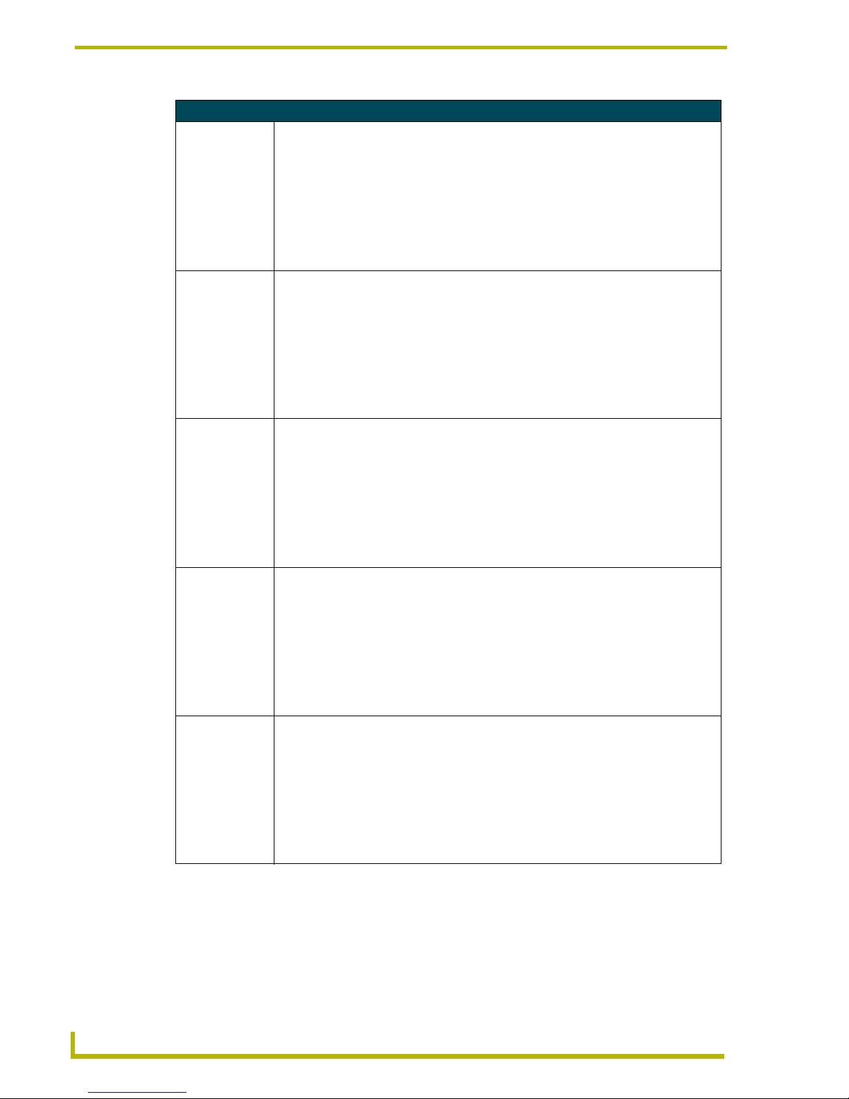
Programming
44
10.4" Touch Panels
Color Send_Commands (Cont.)
CFOFF
Sets the OFF
feedback fill color
to the specified
color.
Syntax:
"’CFOFF<variable text address>-<color_number>’"
Var iables :
variable text address = 1 - 255
color number = See the Colors and Programming Numbers table on page 37.
Example:
SEND_COMMAND TP,"’CFOFF1-72’"
Sets the OFF feedback fill color to White for variable text button 1.
CFON
Sets the ON feedback fill color to
the specified
color.
Syntax:
"’CFON<variable text address>-<color_number>’"
Var iables :
variable text address = 1 - 255
color number = See the Colors and Programming Numbers table on page 37.
Example:
SEND_COMMAND TP,"’CFON1-87’"
Sets the ON feedback fill color to Black for variable text button 1.
CPAGE
Sets the background page color
to the specified
color.
Syntax:
"’CPAGE<color_number>-<page name>’"
Var iables :
color number = See the Colors and Programming Numbers table on page 37.
page name = 1 - 50 ASCII characters (page names are case sensitive.)
Example:
SEND_COMMAND TP,"’CPAGE255-MAIN PAGE’"
Sets the background color on the MAIN PAGE to Transparent.
CTOFF
Sets the OFF
feedback text
color to the specified color.
Syntax:
"’CTOFF<variable text address>-<color_number>’"
Var iables :
variable text address = 1 - 255
color number = See the Colors and Programming Numbers table on page 37.
Example:
SEND_COMMAND TP,"’CTOFF1-87’"
Sets the OFF feedback text color to Black for variable text button 1.
CTON
Sets the ON feedback text color to
the specified
color.
Syntax:
"’CTON<variable text address>-<color_number>’"
Var iables :
variable text address = 1 - 255
color number = See the Colors and Programming Numbers table on page 37.
Example:
SEND_COMMAND TP,"’CTON1-72’"
Sets the ON feedback text color to White for variable text button 1.
Page 49
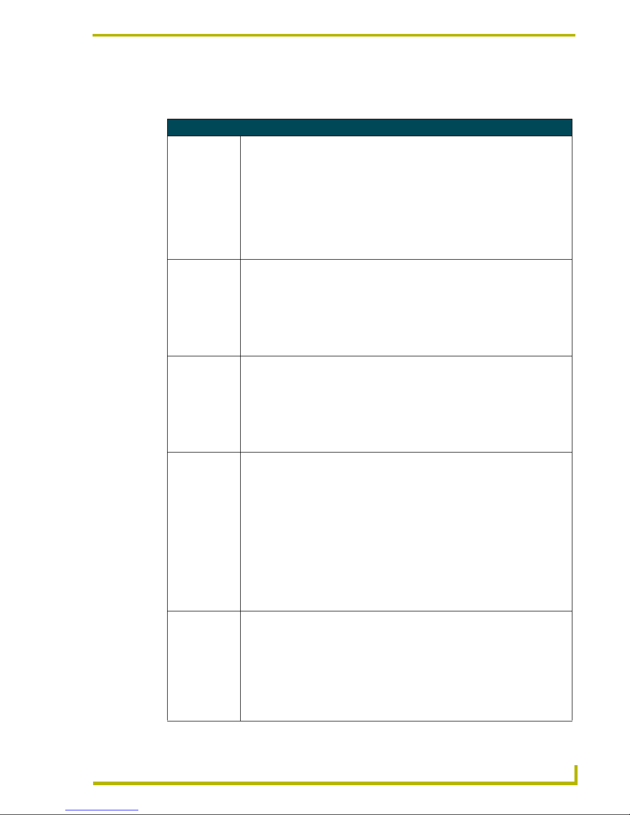
Programming
45
10.4" Touch Panels
Variable Text Send_Commands
Use variable text Send_Commands to set the borders, fonts, and text.
Variable Text Send_Commands
!B
Sets a specific
button to On or
Off.
Syntax:
"’!B’,<variable text address>,<ON/OFF>"
Var iables :
variable text address = 1 - 255
ON = 0
OFF = 1
Example:
SEND_COMMAND TP,"’!B’,128,1"
Sets button 128 Off.
BTOF
Sets a specific
button's active
state to Off.
Syntax:
"’BTOF<variable text address>’"
Var iables :
variable text address = 1 - 255
Example:
SEND_COMMAND TP,"’BTOF255’"
Sets the state for button 255 to Off.
BTON
Sets a specific
button's active
state to On.
Syntax:
"’BTON<variable text address>’"
Var iable:
variable text address = 1 - 255
Example:
SEND_COMMAND TP,"’BTON128’"
Sets the state for button 128 to On.
!C
Sets the border,
font, and text in
one command.
Syntax:
"’!C’,<variable text address>,<border style>,<font
size>,’<new button text>’"
Var iables :
variable text address = 1 - 255
border style = See the Border Styles and Programming Numbers table on page 38.
font size = See the Font Styles and Programming Numbers table on page 37.
new button text = Enter button text to appear on button.
Example:
SEND_COMMAND TP,"’!C’,1,6,6,’VCR PLAY’"
Sets the variable text button one title to VCR PLAY using a hollow medium font, and
changes the border attribute to double rounded.
!F
Shorthand version of ’FONT’
command.
Syntax:
"’!F’,<variable text address>,’<font size>’"
Var iables :
variable text address = 1 - 255
font size = See the Font Styles and Programming Numbers table on page 37.
Example:
SEND_COMMAND TP,"’!F’,1,’6’"
Changes variable text button one font to hollow medium.
Page 50
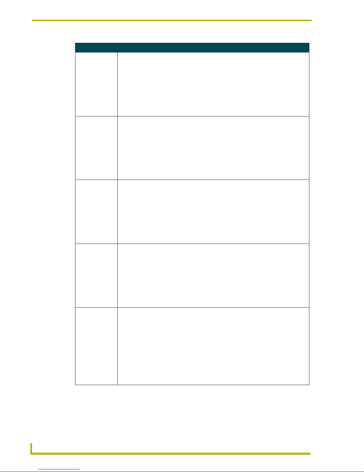
Programming
46
10.4" Touch Panels
Variable Text Send_Commands (Cont.)
FONT
Changes the font
size (or style) of
the text in a specific button.
Syntax:
"’FONT<variable text address>-<font size>’"
Var iables :
variable text address = 1 - 255
font size = See the Font Styles and Programming Numbers table on page 37.
Example:
SEND_COMMAND TP,"’FONT1-6’"
Changes variable text button one font to hollow medium.
!I
Shorthand version of 'ICON'
command.
Syntax:
"’!I’,<variable text address>,’<border style>’"
Var iables :
variable text address = 1 - 255
border style = See the Border Styles and Programming Numbers table on page 38.
Example:
SEND_COMMAND TP,"’!I’,1,’6’"
Changes the variable text button one border style to double rounded.
ICON
Changes the border style of a specific button.
Syntax:
"’ICON<variable text address>-<border style>’"
Var iables :
variable text address = 1 - 255
border style = See the Border Styles and Programming Numbers table on page 38.
Example:
SEND_COMMAND TP,"’ICON25-6’"
Changes the variable text button 25 border style to double-rounded.
!T
Shorthand version of 'TEXT'
command.
Syntax:
"’!T’,<variable text address>,’<new button text>’"
Var iables :
variable text address = 1 - 255
new button text = 1 - 60 characters
Example:
SEND_COMMAND TP,"’!T’,1,’VCR PLAY’"
Changes the variable text button one title to VCR PLAY.
TEXT
Enters text on a
button.
Use the | character to display text on multiple lines.
Syntax:
"’TEXT<variable text address>-<new button text>’"
Var iables :
variable text address = 1 - 255
new button text = Enter button text to appear on button.
Example:
SEND_COMMAND TP,"’TEXT2-VCR|PLAY’"
Sets the VCR and PLAY text on variable button 2. The | character places VCR above
PLAY on the button.
Page 51
Programming
47
10.4" Touch Panels
Shorthand Variable Text Commands
The table below lists the shorthand variable text commands you can use with the touch panel. The
shorthand command data is one-byte, non-ASCII format except for pages, passwords, text, and
bitmap names.
Shorthand Variable Text Commands
@BMF
Sets multiple
attributes to a button, slider, or
gauge. Allows buttons to be moved
and re-sized.
This command allows you to program up to 12 attributes on one command line.
Syntax:
"’@BMF’,<variable text address>,’<attribute data>’"
Var iables :
variable text address = 1 - 255
attribute data :
’%R,<left>, <top>, <right>, <bottom>’ = Sets the Rectangle position.
’%B’,<border styles> = See the Border Styles and Programming Numbers table on
page 38.
’%F’,<font styles> = See the Font Styles and Programming Numbers table on page 37.
’%T’,<button text > = ASCII characters (empty is clear)
’%P’,<bitmap> = Bitmap filename (empty is clear)
’%I’,<icon> = 1 - 255 (icon numbers are assigned in TPDesign3 project file)
’%J’,<text alignment> = 1 - 9 as shown the following alignment chart
For %C1-%C6, see the Colors and Programming Numbers table on page 37.
’%C1’,<on-state fill color>
’%C2',<off-state fill color>
’%C3’,<on-state border color>
’%C4’,<off-state border color>
’%C5’,<on-state text color>
’%C6’,<off-state text color>
Example:
SEND_COMMAND TP,"’@BMF’,255,’%T POWER |ON’
’%B’,’4’,’%C1’,’72’"
Sets the text on button 255 to POWER ON (appears on two lines), adds a triple-line border, and sets the On-state color to White.
@BMP
Adds a bitmap file
to a button.
Bitmap files are imported into TPDesign3; the numbers are assigned by the touch panel
during the download process.
Syntax:
"’@BMP’,<variable text address>,’<bitmap>’"
Var iables :
variable text address = 1 - 255
bitmap = Bitmap chosen from a file location.
Example:
SEND_COMMAND TP,"’@BMP’,85,’Bitmap1’"
Adds the Bitmap1 file to button 85.
1
4
7
8
9
6
3
2
5
Page 52
Programming
48
10.4" Touch Panels
Shorthand Variable Text Commands (Cont.)
@BOR
Sets the border
style on a button.
Syntax:
"’@BOR’,<variable text address>,<border style>"
Var iables :
variable text address = 1 - 255
border style = See the Border Styles and Programming Numbers table on page 38.
Example:
SEND_COMMAND TP,"’@BOR’,65,11"
Sets the border style to Double shadow on button 65.
@ENA
Enables/disables
buttons based on
the variable text
channel.
Syntax:
"’@ENA’,<variable text address>,<disable button on/off>"
Var iables :
variable text address = 1 – 255
disable button on/off=
1 : button disabled
0 : button enabled
Example:
SEND_COMMAND TP,"’@ENA’,128,1"
Disables the button with variable text channel 128. This button will stop responding to
pushes completely, until it is sent an Enable command. Nothing short of a touch panel
SoftROM firmware reload will re-enable the button. Reloading the touch panel file, reloading the Axcess program, or resetting power on the panel or master will not re-enable the
button. It must be sent an Enable command once it has been disabled.
@FON
Sets the text font
on a button.
Syntax:
"’@FON’,<variable text address>,<font style>"
Var iables :
variable text address = 1 - 255
font style = See the Font Styles and Programming Numbers table on page 37.
Example:
SEND_COMMAND TP,"'@FON',56,32"
Sets the text on button 56 to variable font style 32.
@ICO
Assigns an icon to
a button.
Syntax:
"’@ICO’,<variable text address>,<icon file number>"
Var iables :
variable text address = 1 - 255
icon file number = 1 - 255
Example:
SEND_COMMAND TP,"’@ICO’,16,12"
Adds icon 12 on button 16. Setting the icon value to 0 clears the appearance of the icon.
Page 53

Programming
49
10.4" Touch Panels
Shorthand Variable Text Commands (Cont.)
@JUS
Sets the text
alignment on a
button.
Syntax:
"’@JUS’,<variable text address>,<text alignment>"
Var iables :
variable text address = 1 - 255
text alignment = 1 - 9 as shown in the following alignment chart
Example:
SEND_COMMAND TP,"’@JUS’,9,5"
Centers the text on button 9.
@SHO
Sets a specific
button to on or off.
Syntax:
"’@SHO’,<variable text address>,<button on/off>"
Var iables :
variable text address = 1 - 255
button on/off=
0 : button Off
1 : button On
Example:
SEND_COMMAND TP,"’@SHO’,128,0"
Sets button 128 off.
@TXT
Adds text to a button.
Use the | character to display text on multiple lines.
Syntax:
"’@TXT’,<variable text address>,’<text>’"
Var iables :
variable text address = 1 - 255
text = Enter button text to appear on the button.
Example:
SEND_COMMAND TP,"’@TXT’,2,’VCR|PLAY’"
Sets the VCR and PLAY text on variable button 2. The | character places VCR on a text
line above PLAY on the button.
@UNI
Adds Unicode text
to a button.
Characters for Middle Eastern languages, such as Arabic, are not supported within the
Unicode fonts because they are bi-directional. Buttons with Unicode fonts can only be created and edited using TPDesign3 Touch Panel Design Program.
Syntax:
"’@UNI’,<variable text address>,’<text>’"
Var iables :
variable text address = 1 - 255
text = Enter button text to appear on button.
Example:
SEND_COMMAND TP,"’@UNI’,2,’Foreign Text’"
Sets the Foreign Text on variable button 2.
1
4
7
8
9
6
3
2
5
Page 54

Programming
50
10.4" Touch Panels
Button String Commands
The table below lists string commands you can assign to buttons by using the touch panel editor.
Select the PROPERTIES option in the Edit bar, press the target button, and enter the string
command with the Touch Panel keyboard. The string command is sent to the control system
when you press the button.
Button String Commands
$CU
Turns the cursor
display On and
Off.
Syntax:
"$CU <cursor value>"
Var iable:
cursor value = 0 (Off) and 1 (On)
Example:
$CU 0
Turns the cursor Off.
$ID
Sets the WavePack group ID
number.
Syntax:
"’$ID <group ID>’"
Var iables :
group ID = 0 (Off) - 15
Example:
$ID 15
$SC
Sends a serial
port
send_command
within a panel, as
if sent from
Axcess.
Syntax:
"$SC <device offset>,"’<send_command>,<variable
text #>,<data>’""
Var iables :
device offset = Device number
variable text # = The variable text number value on the touch panel.
data = 0 - 59 characters
Example:
$SC 1,"’@TXT’,2,’TEXT’"
The string is sends the command to put text on a button with a variable text value of 2. It is
crucial that all the correct ’ and " be used with no spaces after the commas.
Example:
$SC 1,"’SLEEP’"
Sets a touch panel to sleep.
$SL
Activates sleep
mode on a
wireless touch
panel.
This command does not set the panel to sleep, but actually puts a wavepack to sleep.
Syntax:
"$SL"
Example:
$SL
Activates sleep mode on a wireless touch panel (ViewPoint or other panel using a
SmartPack/WavePack).
Page 55
Programming
51
10.4" Touch Panels
Button String Commands (Cont.)
$SP
Sends data out
through the serial
port of the source
panel to a destination panel.
Syntax:
"$SP"<data>""
Var iables :
data = Serial string command
Examples:
$SP "CALIBRATE"
Sends the Calibrate command to another panel through the Serial Port.
$SP "$SC 1,"’@TXT’,1,’TEST’""
Uses the $SP command to send a Send Command ($SC ***) to another panel through the
Serial Port. This is an on-panel button string that is entered using on-screen keyboard.
$ST
Sets the idle time
to activate sleep
mode for a touch
panel/WavePack
in 1-minute increments.
When the touch panel’s input time matches the sleep time, the panel goes to sleep.
Syntax:
"$ST<sleep timeout>"
Var iable:
sleep timeout = 1 (Off) - 120 (in minutes)
Example:
$ST 5
Sets the touch panel’s sleep time to 5 minutes.
$TO
Sends touch coordinates out
through the program port.
Syntax:
"$TO <touch output enabling via the program port>"
Var iable:
touch output enabling = 0 (Input Touch Only), 1 (Input and Output Touch)
Example:
$TO 0
Sets the panel only to input touch.
WORKING?
Verifies the communication
between touch
panels through
the use of the onpanel editor.
Responding touch panels tell the sending touch panel to change its Main page to the color
white.
Syntax:
"WORKING?"
Example:
• 10.4" panel serial port is connected to TPI program port.
• 10.4" panel wants to verify communication between the TPI and itself.
• 10.4" panel issues "WORKING?" to its serial port. It will be sent as ’$SP "WORKING?".
• TPI receives the command and responds to the 10.4" panel by telling it to set the Main
page background to white.
Page 56

Programming
52
10.4" Touch Panels
Page 57

Upgrading the Firmware
53
10.4" Touch Panels
Upgrading the Firmware
Your PC must be connected to the PROGRAM DB9 connector on the Controller or camera control
unit connector using a Programming Cable in order to upgrade the firmware.
If power is lost during the download process, the unit powers up with the same set of code it had
prior to the download. There is a small window during which a loss of power can be catastrophic. If
power is lost between the erase of flash memory and the completion of copying the new boot code
from RAM to flash memory, the unit will not operate at all when power returns.
If you have not already installed the SoftROM program, do so by following the steps contained on
the AMX Control Disc.
Upgrading the Firmware Using NetLinx Studio
Upgrading Firmware through a COM port
Before beginning with this section, verify that your 10.4" unit is powered and connected to the
NetLinx Master through an AXlink connection. Use this method if you can connect a DB9 cable
to the front PROGRAM port on the NetLinx Master.
1. Select Tools > Master Communication Settings, from the Main menu, to open the
Communication Settings dialog box (FIG. 15).
2. Click on the NetLinx radio box to indicate that you are working with a NetLinx Master (such
as the NXC-ME260).
3. From the Communications Port drop-down list, choose the COM port being used on your PC
to program and communicate to the NetLinx Master.
4. Click the Configure button to open the COM dialog box (FIG. 15) and set the BAUD rate for
the master (according to the DIP switch configuration within the NetLinx device).
The NetLinx Studio application can perform firmware upgrades for both Axcess and
NetLinx devices using the options in the NetLinx Studio Firmware sub-menu.
BEFORE beginning, download the correct TSK files from the AMX.com website.
Refer to the NXC-ME260 Instruction manual for detailed setup information.
FIG. 15 Setting Communication Settings and Baud Rates
This configuration
can be either the
COM port (for DB9
communication from
the PC) or an IP Address
(for Ethernet comm. from
PC)
Page 58

Upgrading the Firmware
54
10.4" Touch Panels
5. Click OK twice to exit from the Master Communication Settings dialog box and to establish
the communication.
6. Select Edit > Preferences, from the General - Communications section
7. Select the Enable Online Tree option to view the Connected devices from within the Project
Navigator window. The next step is to set the System value.
8. After the Communication Verification dialog window verifies active communication between
the PC, the Master and the 10.4-inch touch panel, verify the panel appears in the Online tab of
the Project Navigator window (FIG. 16). Refer to the NetLinx Programming Instruction
Manual for more detailed information about the Online tab and the communication procedures
described above.
9. Right-click on the touch panel and select Properties to confirm the on-board firmware.
10. Select Tools > Firmware > Download to Axcess Device, from the Main menu, to open the
Communication Settings dialog box.
11. Click Browse to navigate to the directory containing the firmware files. Once a directory
containing one or more TSK files is specified, a list of available TSK files is displayed in the
upper table in this dialog (FIG. 17 on page 55).
12. Select the desired Download TSK file from the list of available files.
13. Setup the Download device via section to match the parameters of the Master Comm Settings
dialog box for the method of communicating to the panel. Refer to FIG. 15 on page 53 for
more information.
14. Click OK when done setting the parameters.
15. Click Query Online Devices to populate the on-line device list.
16. Select the target AXlink device from the list of online devices in the lower-left table.
If the connection fails to establish, try selecting a different COM port.
FIG. 16 Sample NetLinx Project Navigator window
Download the latest firmware file from AMX.COM > Tech Center > Downloadable
FIles > Firmware Files > AXT-CA10, AXT-CV10, AXT-CG10. Then Download the TSK
file to your computer.
Page 59
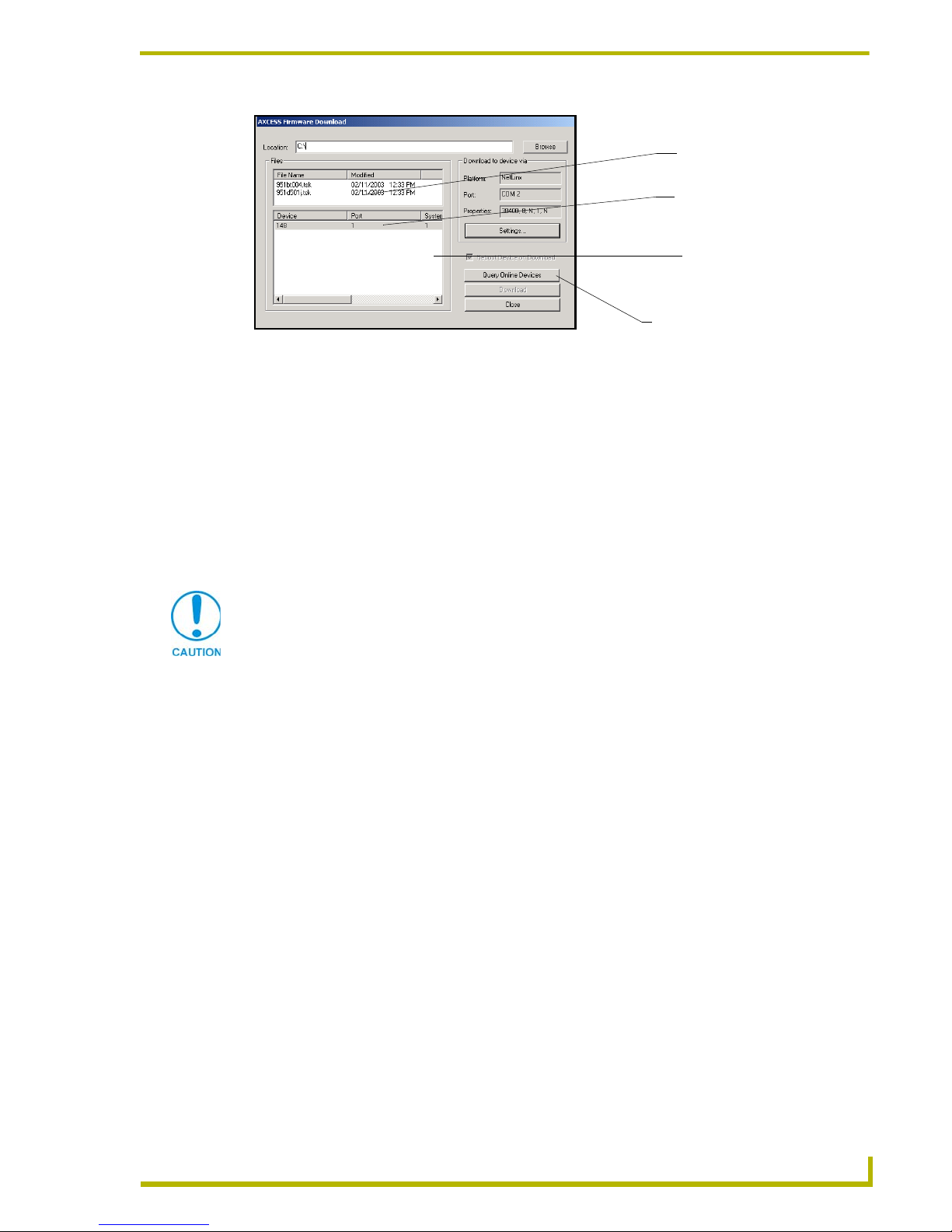
Upgrading the Firmware
55
10.4" Touch Panels
17. Click Download to open the Confirm Communication Settings dialog, where you can review
and confirm your Comm Settings and Target Device information before the download begins.
! Click Cancel to return to the Select Axcess Firmware File dialog, to edit these settings
(if necessary).
! Click OK to confirm the Comm Settings and Target Device information, and download
the selected TSK file to the specified device using the selected communications port.
18. The File Transfer dialog shows the progress of the download. Click Cancel to cancel the
download.
19. Once the TSK file has been downloaded, the 10.4-inch LCD displays the message
"*Touch To Continue*".
20. Touch anywhere on the LCD to return the panel to the Main page (or wait 10-seconds for the
same result).
21. Reboot the touch panel by cycling power to the unit. This step completes the firmware upgrade
procedure.
Upgrading the Firmware through an IP Address
Before beginning with this section, verify that your 10.4-inch unit is powered and connected to the
NetLinx Master through an AXlink connection. Use this method if you can only access the
NetLinx Master through an Ethernet connection.
1. Obtain the IP Address of the NetLinx Master from your System Administrator, if you do not
have an IP Address for the Master:
! Follow steps outlined in the NetLinx Studio Instruction Manual for either Obtaining or
Assigning and IP Address.
! From the Online tab of the Project Navigator window, select the NetLinx Master.
! Press the Get IP button from the Too ls > NetLinx Diagnostics > Networking tab >
IP Address section. Note the IP Address and Gateway information.
FIG. 17 Select New 10.4 Firmware File for download page
Selected Firmware file
Device number listing of
Query Online Devices
of detected Axcess devices
detected Axcess devices
allows the user to refresh the list
Device, Port and system
number of panel.
Canceling the firmware download in mid-progress can damage the on-board
firmware.
Page 60

Upgrading the Firmware
56
10.4" Touch Panels
2. Select Tools > Master Communication Settings from the Main menu.
3. Press the NetLinx radio button from within the Platform section of the Communication
Settings dialog box (FIG. 18).
4. From the Communications Port drop-down list, choose Network. This indicates the
IP Address on the master is being reached from within a network connection.
5. Enter the IP Address information displayed on the Networking tab. Do not alter the defaulted
IP port.
6. Click the OK button to end the process of obtaining and assigning the IP Address to the
NetLinx Master.
7. Select Edit > Preferences, from the General - Communications section
8. Select the Enable Online Tree option to view the Connected devices from within the Project
Navigator window. The next step is to set the System value.
9. After the Communication Verification dialog window verifies active communication between
the PC, the Master and the panel, verify the touch panel appears in the Online tab of the Project
Navigator window (FIG. 19).
10. Right-click on the touch panel and select Properties to confirm the on-board firmware.
FIG. 18 Communication Setting tab
FIG. 19 Sample NetLinx Project Navigator window
Enter an IP Address
Download the latest firmware file from AMX.COM > Tech Center > Downloadable
FIles > Firmware Files > AXT-CA10, AXT-CV10, AXT-CG10. Then Download the TSK
file to your computer.
Page 61

Upgrading the Firmware
57
10.4" Touch Panels
11. Select Tools > Firmware > Download to Axcess Device, from the Main menu, to open the
Communication Settings dialog box.
12. Click Browse to navigate to the directory containing the firmware files. Once a directory
containing one or more TSK files is specified, a list of available TSK files is displayed in the
upper table in this dialog.
13. Select the desired Download TSK file from the list of available files.
14. Setup the Download device via section to match the parameters of the Master Comm Settings
dialog box for the method of communicating to the panel.
15. Click OK when done setting the parameters.
16. Click Query Online Devices to populate the on-line device list.
17. Select the target AXlink device from the list of online devices in the lower-left table.
18. Click Download to open the Confirm Communication Settings dialog, where you can review
and confirm your Comm Settings and Target Device information before the download begins.
! Click Cancel to return to the Select Axcess Firmware File dialog, to edit these settings
(if necessary).
! Click OK to confirm the Comm Settings and Target Device information, and download
the selected TSK file to the specified device using the selected communications port.
19. The File Transfer dialog shows the progress of the download. Click Cancel to cancel the
download.
20. Once the TSK file has been downloaded, the 10.4-inch LCD displays the message
"*Touch To Continue*".
21. Touch anywhere on the LCD to return the 10.4-inch panel to the Main page (or wait
10-seconds for the same result).
22. Reboot the touch panel by cycling power to the unit. This step completes the firmware upgrade
procedure.
Upgrading the Firmware Using SoftROM
Your PC must be connected to the PROGRAM DB9 connector on the Axcess Controller using a
Programming Cable in order to upgrade the firmware in the panel.
If power is lost during the download process, the unit powers up with the same set of code it had
prior to the download. There is a small window during which a loss of power can be catastrophic. If
power is lost between the erase of flash memory and the completion of copying the new boot code
from RAM to flash memory, the unit will not operate at all when power returns.
If you have not already installed the SoftROM program, do so by logging into the AMX.com
site and going to Dealers > Tech Center > Downloadable Files > Firmware Files. Scroll-down
the list of products to find the AXT-CA10, AXT-CV10, AXT-CG10 firmware TSK files.
Canceling the firmware download in mid-progress can damage the on-board
firmware.
Page 62

Upgrading the Firmware
58
10.4" Touch Panels
Configuration
To configure the communication setting for the SoftROM program:
1. Press F1 to open the Configuration screen.
2. Using the up/down arrow keys, select the communications port you are using to interface with
the controller and press ENTER.
3. Using the right arrow key, move to the BAUD RATE column. Then, use the up/down arrow
keys to select the interface communications speed and press ENTER. Be sure the BAUD
RATE selections match the setting on the Controller.
4. Press F10 to save the communication settings and exit the Configure screen.
Downloading the Firmware
To download the firmware:
1. Press F5 to acquire the list of online programmable devices.
2. Using the up/down arrow keys, select your firmware version listed in the Firmware column of
the screen, and press ENTER.
3. Using the Tab key, switch to the ONLINE MASTERS list.
4. Using the up/down arrow keys, select the device to be programmed.
5. Press ENTER for each device as it is selected.
6. Press F4 to program the selected device; a loading message appears.
7. Once the .TSK file has been downloaded, the device, reboot the 10.4" panel so that the
firmware is stored and updated.
8. Press F5 to refresh the screen. Verify that the selected device has the correct firmware version.
If any devices still appear with an old firmware version, repeat steps as necessary until it
appears with the correct version.
9. Press F10 to exit the SoftROM program.
You can press F2 to select all ONLINE programmable devices and F3 to clear all devices.
Firmware can be downloaded to multiple device numbers automatically. If multiple devices are
selected, the bottom half of the loading bar indicates the percentage complete for the selected
devices.
Page 63

Changing the LCD Viewing Angle
59
10.4" Touch Panels
Changing the LCD Viewing Angle
You can reset the viewing angle on the Decor-style wall mount and Rack-mount touch panels to
accommodate the various installation locations and viewing angles. The two most frequent
locations are on a wall or podium. In the first location (wall), a user is looking at the screen from a
12 o’clock position (looking down on it). This view typically requires the user to view images on
the LCD at an angle above the true center of the screen. In the second location (podium), a user is
looking at the screen from a 6 o’clock position (looking up to it). This view requires the user to
view images at an angle below the true center of the screen.
All wall and rack-mount touch panels are factory set to a 12 o’clock viewing angle.
This section describes setting the touch panels to a 6 o’clock viewing angle. Verify that you have a
current copy of your touch panel pages, this avoids any inadvertent loss of data. You will need a
Phillips screwdriver and a non-conducting flat-blade tool to reset the touch panel’s LCD viewing
angle.
Changing the Viewing Angle to 6 o’clock (podium mount)
1. Discharge any built-up static electricity by touching a grounded object.
2. Insert a non-conductive flat-blade tool into the release slot on the touch panels’ bezel/faceplate
and remove the engraved overlay.
3. Remove the four #6-32 CB-TP3 or equipment rack-mounting screws from the unit’s bezel.
4. Separate the main unit (touch panel and CB-TP# backbox) from the bezel/faceplate.
5. Flip the touch panel facedown onto a soft cloth, remove the four #6-32 screws from the rear of
the panel (if applicable), and separate the CB-TP3 backbox from the touch panel unit to expose
the internal circuit card.
6. Note the location and connection points of all of the interior connectors before any
disconnection occurs.
7. Disconnect all internal connectors.
8. Locate JP6 on the circuit board (FIG. 20).
9. Place the JP6 jumper on pins 2 and 3 as shown in FIG. 20. Pins 1and 2 are for the 12 o’clock
position and Pins 2 and 3 are for the 6 o’clock position.
10. Reconnect all of the previously disconnected connectors.
11. Place the CB-TP3 backbox onto the touch panel unit (if applicable).
12. Insert the four #6-32 screws onto the backbox and tighten.
13. Flip the touch panel face-up, rotate the bezel 180 degrees and place it atop the touch panel unit.
14. Insert the bezel mounting screws onto the bezel and tighten.
15. Return the touch panel to the CB-TP3 or equipment rack, and reconnect all external
connectors. Make sure that the release slot is located at the bottom of the touch panel.
16. Insert the four #6-32 mounting screws and tighten. Make sure the unit is securely attached to
its new location.
Page 64
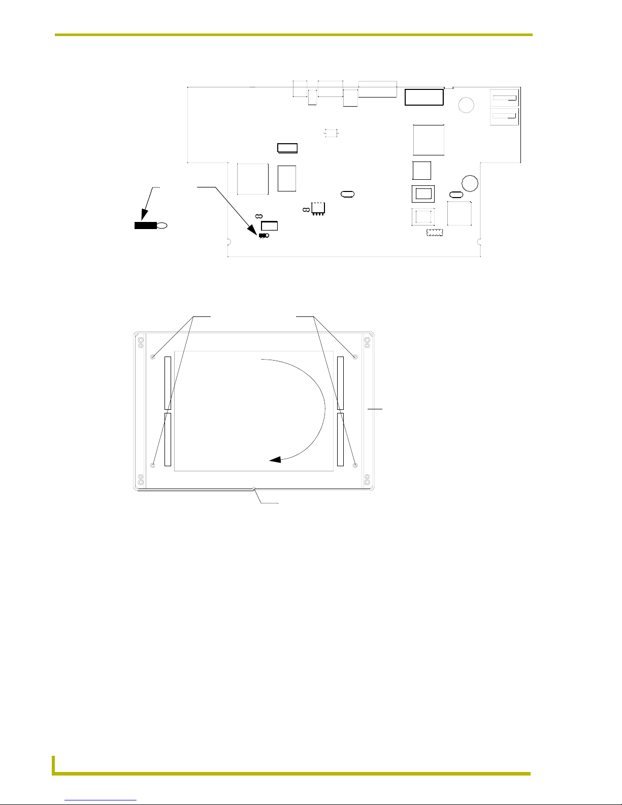
Changing the LCD Viewing Angle
60
10.4" Touch Panels
17. Place the engraved overlay back onto the touch panels’ bezel/faceplate.
FIG. 20 Open circuit card and JP6 jumper location
FIG. 21 Bezel mounting screws and release slot locations
Jumper 6
3 2 1
Bezel mounting screws
Bezel/faceplate
Rotate bezel 180 degrees
Release slot
Page 65

Replacing the Batteries
61
10.4" Touch Panels
Replacing the Batteries
There are two lithium batteries on the touch panel card, with a life of approximately 2.5 years. They
protect stored commands and pages against a power outage. The batteries are not used when DC
power is supplied to the touch panel. Write down the replacement date on a label by adding 2.5
years to the date of installation, and attach it to the panel for future reference.
Before replacing the lithium batteries, make sure you have a current copy of the pages stored in the
touch panel. This will avoid any inadvertent loss of data or a service outage. To replace the lithium
batteries, you will need a Phillips screwdriver and a non-conducting flat-blade tool to slip under
each battery to pry it up and out of the socket.
To replace the lithium batteries in the touch panel:
1. Discharge the static electricity from your body by touching a grounded object.
2. Disconnect all the connectors from the rear side of the touch panel.
3. Flip the touch panel facedown onto a soft cloth, and remove the Phillips-head screws from the
bottom panel. Then, gently remove the panel.
4. Gently rotate the circuit card backward until it lays down flat with the batteries exposed.
5. Using a nonconducting tool, carefully pry one battery from its socket and insert the new battery
observing the polarities indicated on the battery holder.
6. Rotate the circuit card back to the original position and place it in the touch panel housing. Do
not insert any the mounting screws.
7. Plug the AXlink and optional 12 VDC power supply connector back into the touch panel for
approximately 1 minute. Then, remove the connectors from the panel again.
8. Gently rotate the circuit card backward until you can lay it down flat with the batteries
exposed.
9. Using the nonconducting tool, carefully pry the other battery out of its socket. Then, insert the
new battery observing the polarities indicated on the battery holder.
10. Rotate the circuit card back to the original position and place it in the touch panel housing.
11. Place the bottom panel on the touch panel and align the mounting plate and screw holes. Insert
the four Phillips-head screws and tighten.
12. Plug all connectors back into the touch panel.
FIG. 22 Lithium battery and socket
Static electricity can damage electronic circuitry. Before removing the touch panel
circuit card from the enclosure, discharge any accumulated static electricity from your
body and flat-blade tool by touching a grounded metal object.
Page 66

AMX reserves the right to alter specifications without notice at any time.
036-004-1783 6/03
©
2003 AMX Corporation. All rights reserved. AMX, the AMX logo, the building icon, th e home icon, and the light bulb icon are all trademarks of AMX Corporation.
AMX reserves the right to alter specifications without notice at any time. *In Canada doing business as Panja Inc.
ARGENTI NA • AUST RALIA • BELGIUM • BRAZIL • CANADA • CHINA • ENGLAN D • FRANC E • GERMA NY • GRE ECE • HO NG KONG • INDIA • I NDONES IA • ITALY • JAPAN
LEBANON • MALAYSIA • MEXICO • NETHERLANDS • NEW ZEALAND • PHILIPPINES • PORTUGAL • RUSSIA • SINGAPORE • SPAIN • SWITZERLAND • THAILAND • TURKEY • USA
ATLANTA • BOSTON • CHICAGO • CL EVELAND • DALLAS • DENVER • INDIANAPOLIS • LOS ANGELES • MINNEAPOLIS • PHILADELPHIA • PHOENIX • PORTLAND • SPOKANE • TAMPA
3000 RESEARCH DRIVE, RICHARDSON, TX 75082 USA • 800.222.0193 • 469.624.8000 • 469-624-7153 fax • 800.932.6993 technical support • www.amx.com
 Loading...