

Page 1
AXlink Wiring
Considerations
instruction manual
Axcess Central Controllers
Page 2

AMX Limited Warranty and Disclaimer
AMX Corporation warrants its products to be free of defects in material and workmanship under normal use for three
(3) years from the date of purchase from AMX Corporation, with the following exceptions:
• Electroluminescent and LCD Control Panels are warranted for three (3) years, except for the display and touch
overlay components that are warranted for a period of one (1) year.
• Disk drive mechanisms, pan/tilt heads, power supplies, and MX Series products are warranted for a period of one
(1) year.
• AMX Lighting products are guaranteed to switch on and off any load that is properly connected to our lighting
products, as long as the AMX Lighting products are under warranty. AMX Corporation does guarantee the
control of dimmable loads that are properly connected to our lighting products. The dimming performance or
quality cannot be guaranteed due to the random combinations of dimmers, lamps and ballasts or transformers.
• Unless otherwise specified, OEM and custom products are warranted for a period of one (1) year.
• AMX Software is warranted for a period of ninety (90) days.
• Batteries and incandescent lamps are not covered under the warranty.
This warranty extends only to products purchased directly from AMX Corporation or an Authorized AMX Dealer.
All products returned to AMX require a Return Material Authorization (RMA) number. The RMA number is
obtained from the AMX RMA Department. The RMA number must be clearly marked on the outside of each box.
The RMA is valid for a 30-day period. After the 30-day period the RMA will be cancelled. Any shipments received
not consistent with the RMA, or after the RMA is cancelled, will be refused. AMX is not responsible for products
returned without a valid RMA number.
AMX Corporation is not liable for any damages caused by its products or for the failure of its products to perform.
This includes any lost profits, lost savings, incidental damages, or consequential damages. AMX Corporation is not
liable for any claim made by a third party or by an AMX Dealer for a third party.
This limitation of liability applies whether damages are sought, or a claim is made, under this warranty or as a tort
claim (including negligence and strict product liability), a contract claim, or any other claim. This limitation of
liability cannot be waived or amended by any person. This limitation of liability will be effective even if AMX
Corporation or an authorized representative of AMX Corporation has been advised of the possibility of any such
damages. This limitation of liability, however, will not apply to claims for personal injury.
Some states do not allow a limitation of how long an implied warranty last. Some states do not allow the limitation or
exclusion of incidental or consequential damages for consumer products. In such states, the limitation or exclusion of
the Limited Warranty may not apply. This Limited Warranty gives the owner specific legal rights. The owner may
also have other rights that vary from state to state. The owner is advised to consult applicable state laws for full
determination of rights.
EXCEPT AS EXPRESSLY SET FORTH IN THIS WARRANTY, AMX CORPORATION MAKES NO
OTHER WARRANTIES, EXPRESSED OR IMPLIED, INCLUDING ANY IMPLIED WARRANTIES OF
MERCHANTABILITY OR FITNESS FOR A PARTICULAR PURPOSE. AMX CORPORATION
EXPRESSLY DISCLAIMS ALL WARRANTIES NOT STATED IN THIS LIMITED WARRANTY. ANY
IMPLIED WARRANTIES THAT MAY BE IMPOSED BY LAW ARE LIMITED TO THE TERMS OF THIS
LIMITED WARRANTY.
Page 3

Table of Contents
Table of Contents
AXlink Wiring Considerations .................................................................................1
The AXlink Protocol........................................................................................................... 1
AXlink Electrical and Timing Characteristics ..................................................................... 2
Cable Types and Maximum Distances.............................................................................. 2
Pre-manufactured AXlink cable................................................................................................ 2
Power Distribution ............................................................................................................. 3
Calculating AXlink wiring distances.......................................................................................... 3
Liberty Cable & Wire Inc. cables .............................................................................................. 4
Belden 8102-compliant cables ................................................................................................. 4
Category 5-compliant cables.................................................................................................... 4
Using Ground Shielding ........................................................................................................... 5
Xlink Wiring Considerations
i
Page 4

Table of Contents
ii
AXlink Wiring Considerations
Page 5

AXlink Wiring Considerations
This document describes AXlink, wiring topologies, electrical timing and characteristics,
compatible cable types, wiring distance calculations, and wiring diagram examples. AXlink is a
proprietary communication protocol designed by AMX to control up to 255 devices with a Central
Controller using common copper conductors.
The AXlink Protocol
The AXlink communication protocol supports multiple wiring topologies, including star, daisy-
chain, home run, or any combination. AXlink devices are electrically wired in parallel and require a
minimum of three conductors for signal/power ground, AXM, and AXP. An optional fourth
conductor can be used for 12 VDC power distribution. The AXM and AXP AXlink data signals are
differential and require one pair of twisted conductors.
The wiring distances for the AXB-MPE Master Port Expander and AXB-SPE Slave Port Expander
devices are calculated on a per-port basis. The ports on the AXB-MPE and AXB-SPE devices are
isolated and electrically independent with respect to each other.
AXlink Wiring Considerations
The wiring distance specifications describe the total wiring distance between external devices and
the Central Controller. For example, FIG. 1 shows a star wiring topology, and the total wiring
length is 1,200 feet (200 + 300 + 300 + 400 = 1200).
FIG. 1 Star wiring topology example
AXlink Wiring Considerations
1
Page 6

AXlink Wiring Considerations
AXlink Electrical and Timing Characteristics
FIG. 2 shows the electrical and timing characteristics of AXlink. The table below describes each
characteristic.
FIG. 2 AXlink electrical and timing characteristics
Electrical timing characteristics
Parameter Description Min. Typical Max. Units
Trise Rise time for AXM and AXP 0 20.0 µS
Tfall Fall time for AXM and AXP 0 20.0 µS
Vhigh AXM and AXP voltage with respect to AXlink ground 4.6 5.1 V
Vlow AXM and AXP voltage with respect to AXlink ground -0.7 0.4 V
Vdiff Voltage difference between AXM and AXP 1.0 4.2 5.0 V
Capacitance Total capacitance of AXlink bus wiring 37,500 pF
Cable Types and Maximum Distances
Compatible AXlink cable types include those manufactured by Liberty Wire & Cable Inc., and
cables that comply with Category 5 or Belden 8102 standards. To determine the maximum
distances, refer toPower Distribution section on page 3.
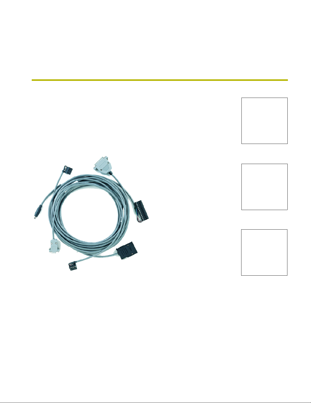
Pre-manufactured AXlink cable
The Liberty Wire & Cable Inc. manufactures AXlink cable that contains two pairs of conductors.
The data pairs comprise 22 AWG stranded shielded twisted pair (STP) with a single drain wire, and
a 12 VDC power pair of 18 AWG stranded wire. The nominal capacitance between the data
conductors is 12.5 pF/ft.
Using the Liberty Wire & Cable Inc. AXlink cable, the maximum overall cable distance between
the Central Controller and all external devices for data communication is 3,000 feet with no remote
power.
You can contact Liberty Wire & Cable Inc. at 4630 Forge Road, Suite A, Colorado Springs, CO
80907 or by calling (800) 530-8998.
2
AXlink Wiring Considerations
Page 7

AXlink Wiring Considerations
Power Distribution
The following table lists the maximum cable lengths by electrical current and wire gauges (AWG).
These distances are based on a min. of 13.5 volts available at the Central Controller's power supply.
Maximum AXlink current and cable lengths by wire AWG
Maximum Current Cable length by wire AWG
Milliampere (mA) 18 AWG 20 AWG 22 AWG 24 AWG
50 2,347 1,485 926 584
100 1,174 743 463 292
250 469 297 185 117
500 235 149 93 58
1,000 117 74 46 29
Calculating AXlink wiring distances
All AXlink devices require a minimum of 12 VDC power to operate properly. The power can be
supplied by the Central Controller's AXlink cable (remote power configuration) or with an optional
12 VDC power supply (local power configuration). The maximum wiring distance between the
power supply and AXlink device is determined by power consumption, supplied voltage, and the
wire gauge used for the cable. Use the three-step formula below to calculate the maximum wiring
lengths allowable between the Central Controller and external AXlink devices.
Most power supplies are factory set to 13.5 VDC. Never use a power supply that exceeds 18 VDC
for remote or local power configurations. Contact AMX for a complete list of products and their
power consumption ratings.
To calculate the AXlink wiring distance formula for data and power:
1. <Total current consumption of all device's on AXlink cable> *<wire resistance per foot> *
2 = <voltage drop per foot>. See tables below for the Wire Resistance/Foot values.
2. <Power supply voltage> - 12 VDC = <surplus voltage dissipation for cable run>.
3. <Surplus voltage dissipation for cable run> / < voltage drop per foot > =
Maximum distance in feet.
The following table lists the resistance factors used in the formula.
Gauge/resistance factors - Solid Copper Wiring
Wire gauge Wire Resistance/foot
18 AWG .00639
20 AWG .0101
22 AWG .0162
24 AWG .0257
Gauge/resistance factors - Stranded Copper Wiring
Wire gauge Wire Resistance/foot
18 AWG .00692
20 AWG .01090
22 AWG .01690
24 AWG .02770
AXlink Wiring Considerations
3
Page 8
AXlink Wiring Considerations
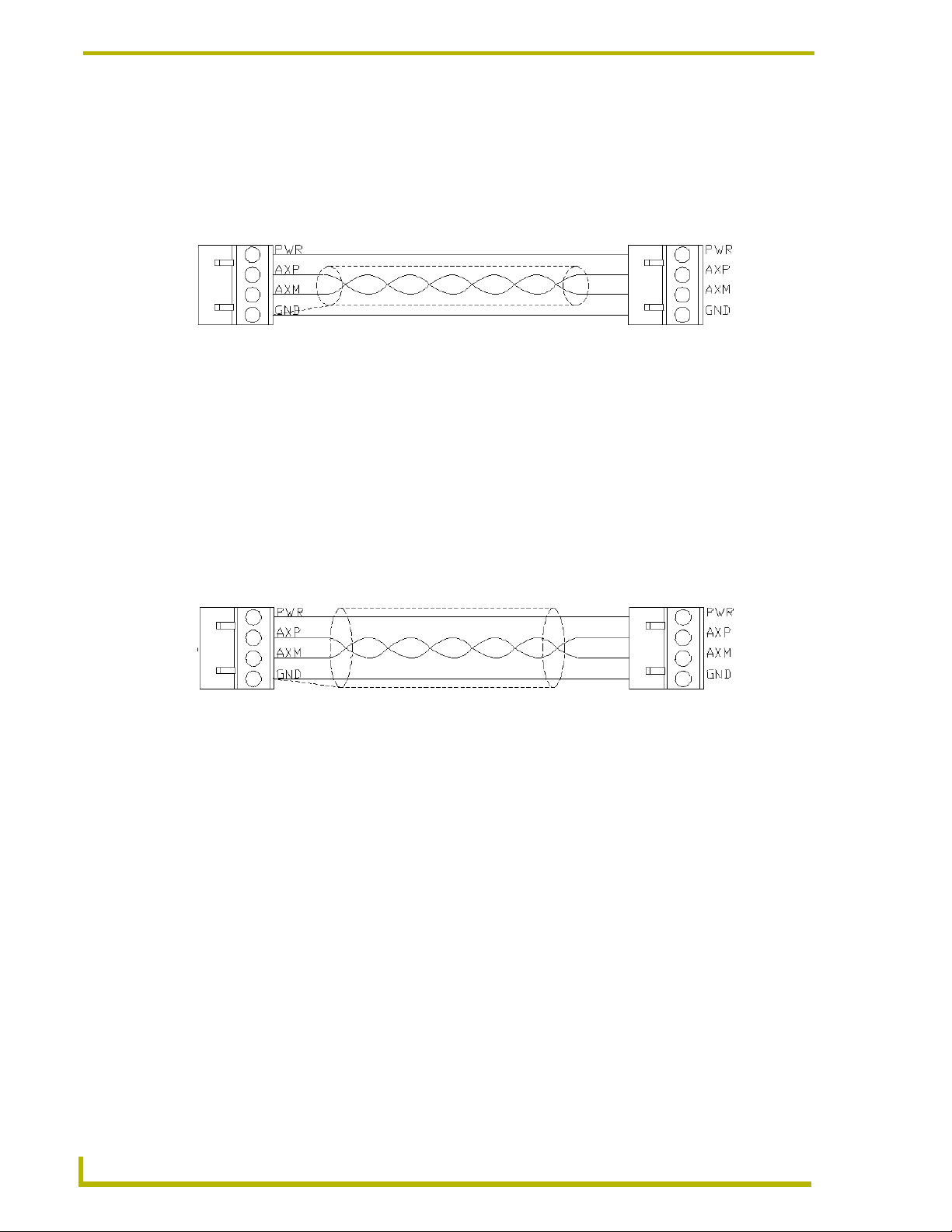
Liberty Cable & Wire Inc. cables
FIG. 3 shows a wiring diagram for AXlink cables manufactured by Liberty Cable & Wire Inc. The
PWR connection shown in the diagram is only used when supplying 12 VDC via the AXlink cable.
The PWR connection should not be used when a local power supply is connected directly to the
external AXlink device.
FIG. 3 Standard AXlink power/data wiring diagram
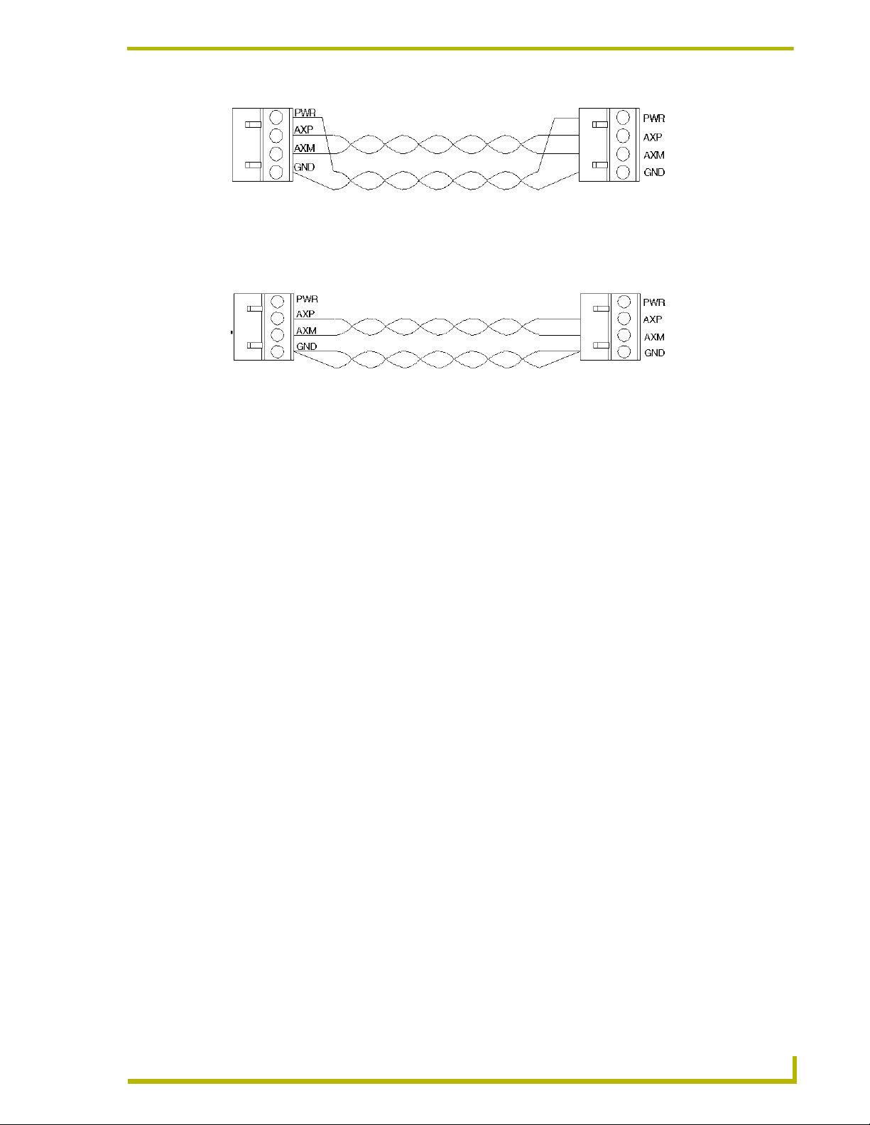
Belden 8102-compliant cables
Belden 8102-compliant cable contains two single twisted pairs (STP) of 24 AWG with a single
drain wire. The nominal capacitance between conductors is 12.5 pF/ft. Using Belden 8102-
compliant cable for AXlink data communication, the maximum overall cable distance between the
Central Controller and all external devices is 3,000 feet with no remote power.
FIG. 4 shows a wiring diagram for the AMX-approved Belden 8102 AXlink cable. The PWR
connection shown in the wiring diagram is only used when supplying 12 VDC via the AXlink
cable. The PWR connection should not be used when a local power supply is connected directly to
the external AXlink device.
FIG. 4 Belden 8102 wiring diagram
Category 5-compliant cables
Category 5 cable contains four unshielded twisted pairs (UTP) of 24 AWG solid wire. The nominal
capacitance between conductors is 15.0 pF/ft. Using Category 5-compliant cable for AXlink data
communication, the maximum overall distance between the Central Controller and all external
devices is 1,000 feet. If the installation site's wiring conforms to EIA/TIA 568 Category 3
standards, AXlink data communication will function properly. However, power (PWR) cannot be
used with EIA/TIA 568-Category 3 standard cable because of connector types and punch blocks.
FIG. 5 shows a wiring diagram for Category 5-compliant cable used for AXlink data
communication. The PWR connection shown in the wiring diagram is only used when supplying 12
VDC via the AXlink cable. The PWR connection should not be used for EIA/TIA 568 cable
installations.
4
AXlink Wiring Considerations
Page 9
AXlink Wiring Considerations
FIG. 5 Category 5 wiring diagram (with PWR connection)
If a local power supply is used, the free GND wire of the GND pair should be connected as shown
in FIG. 6.
FIG. 6 Category 5 wiring diagram (without PWR connection)
Using Ground Shielding
Under normal circumstances ground shielding should not be necessary. Only use ground shielding
when experiencing noise in the line. The shield connection should only be tied on one end - the
Master side.
Tying both ends can result in a ground loop. Tie the ground shield connection to the Master side
only.
AXlink Wiring Considerations
5
Page 10

AMX reserves the right to alter specifications without notice at any time.
ARGENTI NA • AUST RALIA • BELGIUM • BRAZIL • CANADA • CHINA • ENGLAN D • FRANC E • GERMA NY • GRE ECE • HO NG KONG • INDIA • I NDONES IA • ITALY • JAPAN
LEBANON • MALAYSIA • MEXICO • NETHERLANDS • NEW ZEALAND • PHILIPPINES • PORTUGAL • RUSSIA • SINGAPORE • SPAIN • SWITZERLAND • THAILAND • TURKEY • USA
ATLANTA • BOSTON • CHICAGO • CLEVELAND • DALL AS • DENVER • INDIANAPOLIS • LOS ANGELES • MINNEAPOLIS • PHILADELPHIA • PHOENIX • PORTLAND • SPOKANE • TAMPA
3000 RESEARCH DRIVE, RICHARDSON, TX 75082 USA • 800.222.0193 • 469.624.8000 • 469-624-7153 fax • 800.932.6993 technical support • www.amx.com
2005 AMX Corporation. All rights reserved. AMX, the AMX logo, the building icon, th e home icon, and the light bulb icon are all trademarks of AMX Corporation.
©
052-004-1729 9/05
In Canada doing business as Panja Inc.
Last Revision: 9/28/05
 Loading...