

Page 1
instruction manual
Design XPress for
NetLinx Studio
version 1.5
Programmer’s Guide
Page 2

Software License and Warranty Agreement
LICENSE GRANT.
AMX grants to Licensee the non-exclusive right to use the AMX Software in the manner described in this License. The AMX Software
is licensed, not sold. The AMX Software consists of generally available programming and development software, product
documentation, sample applications, tools and utilities, and miscellaneous technical information. Please refer to the README.TXT
file on the compact disc or download for further information regarding the components of the AMX Software. The AMX Software is
subject to restrictions on distribution described in this License Agreement. YOU MAY NOT LICENSE, RENT, OR LEASE THE AMX
SOFTWARE. You may not reverse engineer, decompile, or disassemble the AMX Software.
INTELLECTUAL PROPERTY.
The AMX Software is owned by AMX and is protected by United States copyright laws, patent laws, international treaty provisions,
and/or state of Texas trade secret laws. Licensee may make copies of the AMX Software solely for backup or archival purposes.
Licensee may not copy the written materials accompanying the AMX Software.
TERMINATION. AMX RESERVES THE RIGHT, IN ITS SOLE DISCRETION, TO TERMINATE THIS LICENSE FOR
ANY REASON AND UPON WRITTEN NOTICE TO LICENSEE.
In the event that AMX terminates this License, the Licensee shall return or destroy all originals and copies of the AMX Software to
AMX and certify in writing that all originals and copies have been returned or destroyed.
PRE-RELEASE CODE.
Portions of the AMX Software may, from time to time, as identified in the AMX Software, include PRE-RELEASE CODE and such
code may not be at the level of performance, compatibility and functionality of the final code. The PRE-RELEASE CODE may not
operate correctly and may be substantially modified prior to final release or certain features may not be generally released. AMX is
not obligated to make or support any PRE-RELEASE CODE. ALL PRE-RELEASE CODE IS PROVIDED "AS IS" WITH NO
WARRANTIES.
LIMITED WARRANTY.
AMX warrants that the AMX Software will perform substantially in accordance with the accompanying written materials for a period of
ninety (90) days from the date of receipt. AMX DISCLAIMS ALL OTHER WARRANTIES, EITHER EXPRESS OR IMPLIED,
INCLUDING, BUT NOT LIMITED TO IMPLIED WARRANTIES OF MERCHANTABILITY AND FITNESS FOR A PARTICULAR
PURPOSE, WITH REGARD TO THE AMX SOFTWARE. THIS LIMITED WARRANTY GIVES YOU SPECIFIC LEGAL RIGHTS.
Any supplements or updates to the AMX SOFTWARE, including without limitation, any (if any) service packs or hot fixes provided to
you after the expiration of the ninety (90) day Limited Warranty period are not covered by any warranty or condition, express, implied
or statutory.
LICENSEE REMEDIES.
AMX's entire liability and your exclusive remedy shall be repair or replacement of the AMX Software that does not meet AMX's
Limited Warranty and which is returned to AMX. This Limited Warranty is void if failure of the AMX Software has resulted from
accident, abuse, or misapplication. Any replacement AMX Software will be warranted for the remainder of the original warranty period
or thirty (30) days, whichever is longer. Outside the United States, these remedies may not available.
NO LIABILITY FOR CONSEQUENTIAL DAMAGES. IN NO EVENT SHALL AMX BE LIABLE FOR ANY DAMAGES
WHATSOEVER (INCLUDING, WITHOUT LIMITATION, DAMAGES FOR LOSS OF BUSINESS PROFITS, BUSINESS
INTERRUPTION, LOSS OF BUSINESS INFORMATION, OR ANY OTHER PECUNIARY LOSS) ARISING OUT OF THE USE OF OR
INABILITY TO USE THIS AMX SOFTWARE, EVEN IF AMX HAS BEEN ADVISED OF THE POSSIBILITY OF SUCH DAMAGES.
BECAUSE SOME STATES/COUNTRIES DO NOT ALLOW THE EXCLUSION OR LIMITATION OF LIABILITY FOR
CONSEQUENTIAL OR INCIDENTAL DAMAGES, THE ABOVE LIMITATION MAY NOT APPLY TO YOU.
U.S. GOVERNMENT RESTRICTED RIGHTS. The AMX Software is provided with RESTRICTED RIGHTS. Use, duplication, or
disclosure by the Government is subject to restrictions as set forth in subparagraph (c)(1)(ii) of The Rights in Technical Data and
Computer Software clause at DFARS 252.227-7013 or subparagraphs (c)(1) and (2) of the Commercial Computer Software
Restricted Rights at 48 CFR 52.227-19, as applicable.
This Agreement replaces and supercedes all previous AMX Software License Agreements and is governed by the laws
of the State of Texas, and all disputes will be resolved in the courts in Collin County, Texas, USA. Should you have any
questions concerning this Agreement, or if you desire to contact AMX for any reason, please write: AMX Corporation,
3000 Research Drive, Richardson, TX 75082.
Page 3

Table of Contents
Table of Contents
Introduction ...............................................................................................................1
Minimum System Requirements for DXP v1.5: ................................................................. 1
Required Applications .............................................................................................................. 2
Version Information .................................................................................................................. 2
DXP v1.5 System Capabilities........................................................................................... 2
DXP v1.5 Configuration Capabilities ........................................................................................ 2
Supported Subsystems and Equipment ............................................................................ 3
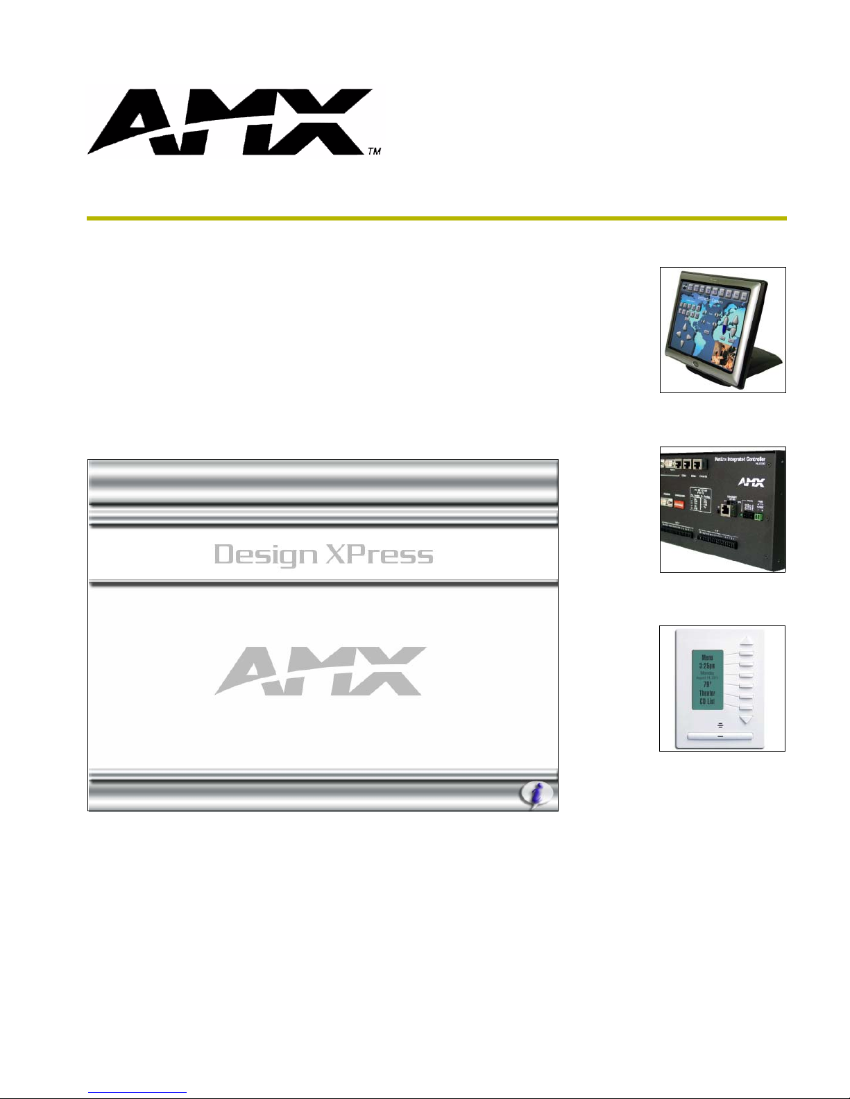
AMX NetLinx Integrated Controllers......................................................................................... 3
AMX Touch Panels .................................................................................................................. 3
MAX Content Servers by AMX ................................................................................................. 4
Lighting..................................................................................................................................... 4
HVAC/Environment .................................................................................................................. 4
Whole House A/V Selection and Distribution ........................................................................... 4
MP3 Players............................................................................................................................. 4
User Interfaces......................................................................................................................... 5
Doorphones.............................................................................................................................. 5
Supported integration!Solutions Applications........................................................................... 5
Related Documents........................................................................................................... 5
Downloading the Application ............................................................................................. 6
Web Update ...................................................................................................................... 6
Design XPress Main Screen ............................................................................................. 6
Project Selection List......................................................................................................... 7
Project Selection List context menu ......................................................................................... 7
Project Sorting.......................................................................................................................... 8
Menu Bar........................................................................................................................... 8
File Menu ................................................................................................................................. 8
Edit Menu ................................................................................................................................. 9
Edit DSS Channels sub-menu ................................................................................................. 9
View Menu ............................................................................................................................... 9
Help Menu.............................................................................................................................. 10
Main Screen Command Buttons ..................................................................................... 10
Setting Program Preferences .......................................................................................... 10
Custom Modifications ...................................................................................................... 11
Adding and Modifying Software ............................................................................................. 11
Common Mistakes ................................................................................................................. 12
esign XPress Programmer’s Guide
i
Page 4

Table of Contents
Using the Design XPress Project Wizard .............................................................15
Overview ......................................................................................................................... 15
Required Information.............................................................................................................. 15
Launching the Design XPress Project Wizard ................................................................ 16
Project Wizard Navigation Controls ....................................................................................... 16
Using the Design XPress Project Wizard........................................................................ 17
User Information dialog ................................................................................................... 17
System Information dialog............................................................................................... 18
To add a new Room/Location name ...................................................................................... 19
To rename an existing Room/Location name ........................................................................ 19
System Configuration dialog ........................................................................................... 20
Which Screens? dialog ................................................................................................... 21
Audio Zones dialog ......................................................................................................... 22
Setting Up Audio/Video Zones ............................................................................................... 23
Audio Sources dialog ...................................................................................................... 25
Selecting Audio Sources ........................................................................................................ 26
Format of IR Files For Audio Sources .................................................................................... 27
Video Inputs dialog.......................................................................................................... 28
HVAC Zones dialog......................................................................................................... 29
Naming HVAC Zones............................................................................................................. 30
DMS Keypads dialog....................................................................................................... 30
Specifying a location for each keypad.................................................................................... 31
Configuring audio, HVAC and intercom zone control for each keypad .................................. 32
Configuring lighting zone control for each keypad ................................................................. 32
Copying a lighting scene layout from another DMS keypad in the system ............................ 32
SB2 Keypads dialog........................................................................................................ 33
Configuring SB2 Keypads ...................................................................................................... 34
Edit Rooms/Locations dialog.................................................................................................. 34
Door Phones dialog......................................................................................................... 34
Configuring Door Phones....................................................................................................... 35
Touch Panel Declarations dialog .................................................................................... 36
Creating Touch Panel Declarations ....................................................................................... 37
Adding a New Touch Panel Interface:.................................................................................... 37
Choose Background Images dialog ................................................................................ 38
Choose Button Colors dialog .......................................................................................... 39
Choose Button Text Colors dialog .................................................................................. 40
Choose Bargraph Color dialog........................................................................................ 41
Touch Panel Control dialogs ........................................................................................... 42
Address Formats For Supported Lighting Systems ............................................................... 43
ii
Design XPress Programmer’s Guide
Page 5

Table of Contents
Note for ALD-D48 Lighting Systems ...................................................................................... 43
Note for Radia Lighting Systems............................................................................................ 44
House Lighting Scenes dialog......................................................................................... 44
Control Button Labels dialog ........................................................................................... 45
CD Titles dialog ............................................................................................................... 46
CD Titles Maintenance dialog ................................................................................................ 47
Adding a new CD title............................................................................................................. 47
Editing CD Information ........................................................................................................... 48
Retrieving CD Information (from freedb.org).......................................................................... 48
Removing a CD Title .............................................................................................................. 48
DSS TV Favorites dialog ................................................................................................. 48
Adding a New DSS TV Channel ............................................................................................ 49
Removing a DSS TV Channel................................................................................................ 49
Changing the Name and/or Channel number on an Existing TV Channel............................. 49
DSS Music Favorites dialog ............................................................................................ 50
Adding a New DSS Music Channel........................................................................................ 51
Removing a DSS Music Channel ........................................................................................... 51
Tuner Presets dialog ....................................................................................................... 51
Finishing a Project........................................................................................................... 52
Understanding the Report File ........................................................................................ 53
Installation Instructions........................................................................................................... 53
Device Addressing ................................................................................................................. 53
Wiring/Connections ................................................................................................................ 54
General Information ............................................................................................................... 54
AMX Recommended Equipment List ..................................................................................... 54
Transferring Preset Button Text to the Master via FTP................................................... 54
Opening an Existing Design XPress Project ................................................................... 55
Copying a Design XPress Project ................................................................................... 55
Copy Project dialog ................................................................................................................ 55
Importing a Design XPress Project ................................................................................. 56
Exporting a Design XPress Project ................................................................................. 56
Deleting a Design XPress Project ................................................................................... 56
Using NetLinx Studio....................................................................................................... 57
Working With Your Project ..................................................................................................... 57
Setting Up the Master ............................................................................................................ 57
Addressing the System .......................................................................................................... 58
Addressing the Devices ......................................................................................................... 58
Downloading Software and Transferring Files ....................................................................... 59
esign XPress Programmer’s Guide
iii
Page 6

Table of Contents
iv
Design XPress Programmer’s Guide
Page 7
Introduction
Design XPress ™ version 1.5 is a software package to allow AMX dealers to more quickly install a
system that can distribute audio and video in a multi-room environment, control thermostats and
lighting, provide intercom functionality, and display weather data.
Design XPress (DXP) allows control from touch panels, DMS keypads, and SB2 keypads. Refer to
Supported Subsystems and Equipment topic for a complete listing of supported equipment.
The DXP Project Wizard also allows you to specify the type of NetLinx Master Controller to be
used to control the system. DXP supports NetLinx Integrated (NI) Controllers (NI-2000/3000/
4000), and the NXI equipped with an NXC-ME260/64 Master card. The Project Wizard will only
allow you to choose a NetLinx Master that is able to accommodate the devices and functions
specified in your Project.
Once the steps outlined in the wizard are complete, the wizard will automatically generate all
NetLinx program files, touch panel files and a comprehensive report file for the system. While
these auto-generated program files can be used as-is, they can also be modified using NetLinx
Studio™, allowing you to customize the NetLinx code and touch panel files to accommodate
specific client desires and unique requirements always found in custom installations.
Introduction
AMX University offers several courses that teach basic and advanced NetLinx
programming and system design concepts. Contact AMX University, or refer to the
Training@AMX University page at http://www.amx.com/ for details and scheduling
information.
Minimum System Requirements for DXP v1.5:
Windows 2000® (Service Pack 4) with at least 128 MB of installed memory
Windows XP® Professional (Service Pack 1) with at least 256 MB of installed memory
Supported language versions: English, French, German and Spanish
If you are installing NetLinx Studio on a Windows XP or 2000, you must have
Administrator rights to install and run all required System files.
Pentium 450 MHZ processor (700 MHZ or faster recommended)
A VGA monitor running at a minimum resolution of 800 x 600
Windows-compatible CD-ROM drive
Mouse (or equivalent pointing device)
Minimum free disk space: 2 GB
Internet Access (for Web Update functionality)
esign XPress Programmer’s Guide
1
Page 8

Introduction
Required Applications
The following applications must be installed on your PC before DXP v1.5 can be installed:
Microsoft MDAC v2.6 (or higher)
NetLinx Studio v2.2 (build 83 or higher)
TPDesign v3.16 (build 199 or higher)
TPDesign4 v2.4 (build 406 or higher)
KPDesign 1.0 (or higher)
DXP Image File - If the application fails to detect at least one valid set of background
images, and at least one valid set of button images, a separate installation of the Image
File is required. This image installation is available on the DXP section of the
Application Files page on www.amx.com.
Version Information
The DXP version information is located on the Main Screen (under the Exit button - for example
"v1.5 Build 136"). It is important to have the version information when calling AMX Technical
Support. The version information will allow Tech Support to determine if software updates or
patches may be available.
This version information includes the version and build number of the actual DXP application. A
change in the Version number indicates a change in the functionality of the application. A change in
the Build number indicates an enhancement in the current functionality of the current revision.
Every change to the Version number will also change the build number, but not every change to the
Build number will change the Version number.
DXP v1.5 System Capabilities
Design XPress (DXP) is a Wizard which quickly creates a multi-room control system file set. DXP
generates all required TPD and KPD files along with NetLinx Studio project files. Additionally a
DXP-generated HTML file identifies the specific hardware addressing and cabling configuration
required for setting up the control system hardware. All DXP-created files will operate the control
system without further modification. Add only the manufacturer-specific IR files for each Audio
and Video source to complete the control system. Refer to the Format of IR Files For Audio
Sources section on page 27.
For more customized user interfaces, use TPDesign4 or TPDesign3 to easily customize the Touch
Panel pages and/or buttons to the end-users' preferences in colors and/or button shapes and sizes.
An advanced NetLinx programmer may also use NetLinx Studio to modify The NetLinx source
code for greater customization of the control system.
DXP v1.5 Configuration Capabilities
1-30 Audio Zones
1-8 Audio/Video Sources (MAX by AMX, CD/DVD, CD Changer, DSS, MP3 Players or
Tuners)
1-32 DMS Keypads
2
Design XPress Programmer’s Guide
Page 9

1-16 Touchpanels
0-32 HVAC Zones (ViewStat ICSNet, ViewStat RS-422 or OPStat)
0-32 SB2 Keypads
0-4 Door Phones (Techlon Instruments, Inc. or Generic I/O based)
0-24 Video Inputs
Supported Subsystems and Equipment
Design XPress (v1.5) supports the following subsystems and equipment:
AMX NetLinx Integrated Controllers
NI-2000
NI-3000
NI-4000
NXC-ME260/64
AMX Touch Panels
Introduction
G4 Firmware Panels:
MVP-7500: Wireless Panel
MVP-8400: Wireless Video Panel
NXT/NXD-CV7: 7" Touch Panel with video
NXT/NXD-CA12: 12" Touch Panel
NXT/NXD-CV12: 12" Touch Panel with video
NXT/NXD-CA15: 15" Touch Panel
NXT/NXD-CV15: 15" Touch Panel with video
NXT/NXD-CV17: 17" Touch Panel with video
The nomenclature " NXT" indicates the table-top (tilt) model, and "NXD" represents
the wall-mount version.
G3 Firmware Panels:
AXT/AXD-CP4/A: 4" Touch Panel
AXD-CV6: 6" Video Touch Panel
AXT/AXD-CA10: 10" Touch Panel
AXT/AXD-CG10: 10" Touch Panel
AXT/AXD-CV10: 10" Video Touch Panel
esign XPress Programmer’s Guide
3
Page 10

Introduction
The nomenclature " AXT" indicates the table-top (tilt) model, and "AXD" represents
the wall-mount version.
Note: G3 panels do not support PictureFrame.
MAX Content Servers by AMX
MAX-MMS MultiMedia Servers
MAX-IMS Integrated Music Servers
MAX-BSM Backup Storage Module
MAX-AVM Audio/Video Module
Lighting
AMX ALD-D48 (FW build 2.1 or later, via ISCP only)
AMX Radia
Clipsal C-Bus
DynaLite
LiteTouch 5000LC
Lutron GRAFIK Eye
Lutron Homeworks Interactive
Lutron RadioRA
Vantage Q
The Clipsal C-Bus and Dynalite lighting systems are primarily used outside the U.S.
HVAC/Environment
AMX OPStat thermostats
AMX ViewStat thermostats (ICSNET and RS-422)
Whole House A/V Selection and Distribution
AMX AS8/16 audio switcher
PLH-VS8 video switcher
Any audio or video source equipment that uses IR
MP3 Players
Integra NAS-2.3 Net-Tune (XIVA protocol-controlled)
Imerge SoundServer (XIVA protocol-controlled)
4
Design XPress Programmer’s Guide
Page 11
Marantz DH9300 (XIVA protocol-controlled)
ReQuest ARQ2
Any XIVA protocol MP3 player can be used by specifying one of the supported XIVA
MP3 players, and physically connecting a different player (since the XIVA protocol is
the same across all devices that use it). In this case the name of the player will be
represented by DXP as the selected make and model MP3 player, as opposed to the
actual make/model of the connected MP3 player.
User Interfaces
AMX Touch Panels
AMX DMS keypads
AMX SB2 keypads (for volume control only)
Doorphones
Generic
Techlon Instruments
Introduction
Supported integration!Solutions Applications
i!-Weather
i!-TimeManager
i!-Schedule
Related Documents
This document will not attempt to explain the architecture of the NetLinx software that is
automatically generated by Design XPress. That is left for another document and potentially
another audience. The related documents listed below are all available (as PDF files) on-line at
www.amx.com.
Related Documents
• Design XPress for NetLinx Studio Installer’s Guide Describes installing Design XPress systems.
• Design XPress for NetLinx User Interface Guide Provides a detailed description of the Design XPress for
• NetLinx Studio Instruction Manual Provides a detailed description of the NetLinx Studio
• NetLinx Programming Language Reference Guide Provides a comprehensive listing of the commands that
NetLinx Studio user-interface.
software application.
comprise the NetLinx Programming Language.
AMX University offers several courses that teach basic and advanced NetLinx
programming and system design concepts. Contact AMX University, or refer to the
Training@AMX University page on AMX.COM for details and scheduling information.
esign XPress Programmer’s Guide
5
Page 12

Introduction
Downloading the Application
Design XPress can be downloaded from the AMX web site. You must first log in as a registered
user to the AMX web site then, you can proceed to the Software Center to download the
application. We recommend that you download all of the files in the Design XPress directory, or
you may download the compressed file, which contains all of the other files in the directory.
The three Adobe Acrobat files included are intended for different audiences:
The Programmer's Guide is intended for the person using the Design XPress
application.
The Installer's Guide is intended for the person who will be installing the equipment in
the project.
The User Interface Guide is intended for designers, installers, and end-users as a
reference.
Web Update
The AMX WebUpdate program is a stand-alone application that:
Communicates with the AMX website
Allows a user to select from a list of updateable AMX Software programs
Determines the latest version of the selected applications
Returns a listing of available updates and allows a user to download the selected
installation files
Upon request, launches the installation of those downloads
DXP requires the latest versions of the following applications be loaded prior to the
running the DXP installation executable: NetLinx Studio 2.X, KPDesign, TPD4, and
TPD3. Use the WebUpdate program to obtain the latest versions of these previously
installed products.
Select Help > Web Update to launch this application.
Refer to the WebUpdate on-line help for details and instructions.
The WebUpdate program should also be checked for any available updates to itself.
Design XPress Main Screen
When Design XPress is launched, the first screen to be displayed is the Main Screen (FIG. 1). Use
the Main Screen as the starting point for creating new projects, opening existing projects. The main
page also contains command buttons for copying projects and deleting projects.
The main element on the Main Page is a table called the Project Selection List. When Design
XPress is launched for the first time, one sample project is listed in this table (called "Sample
Whole House", Rev "0").
Before creating a new project, you should consider opening the sample project and quickly going
through the various Wizard dialogs, to become familiar with the program.
6
Design XPress Programmer’s Guide
Page 13
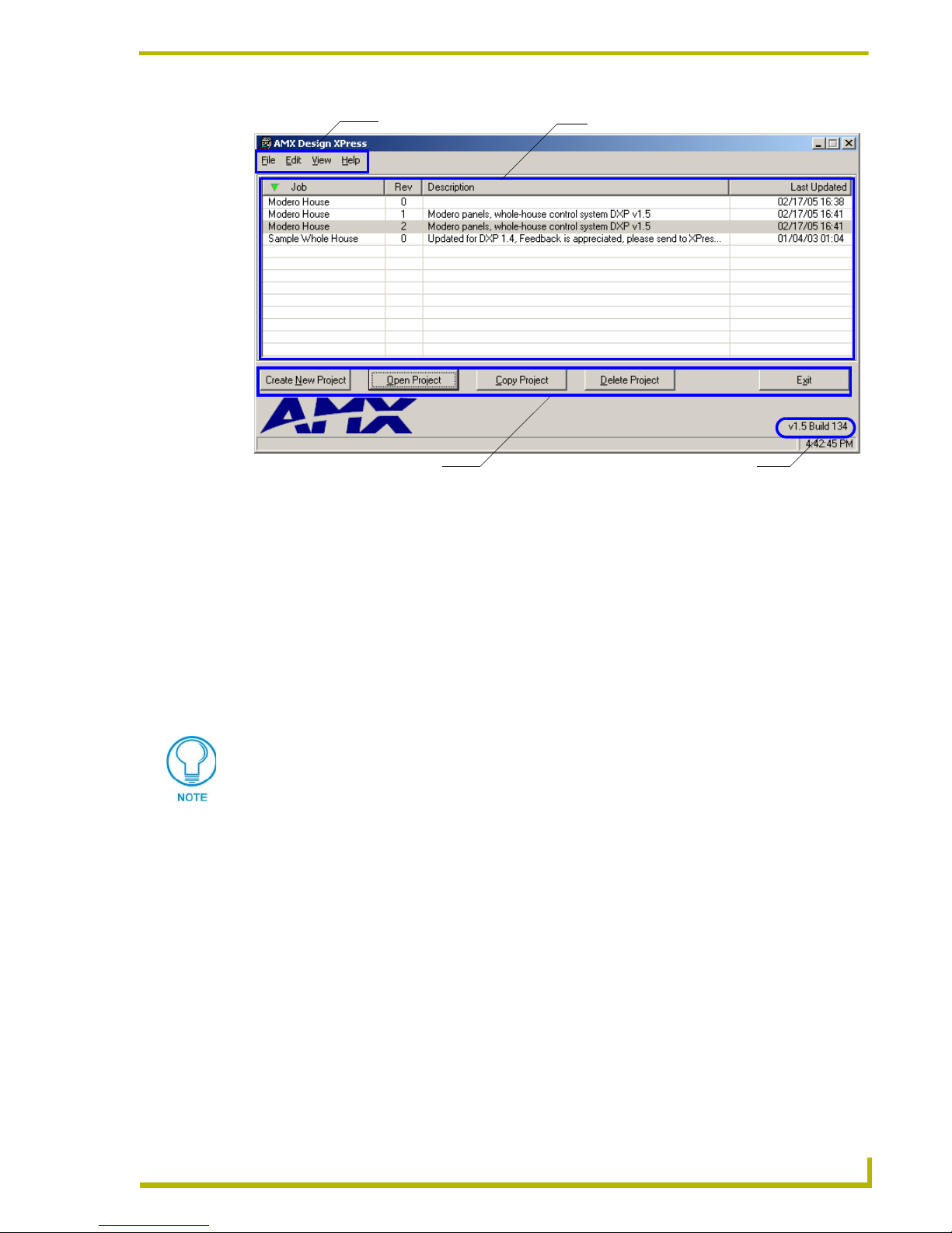
Menu Bar Project Selection List
Introduction
Command Buttons
FIG. 1 Design XPress Main Screen
Version/Release Information
Project Selection List
The Project Selection List is displayed on the Design XPress Main Screen (along with the main
menu and the command buttons). It is a list of all Design XPress Projects that have been created (or
imported) and saved in Design XPress.
To open a project, select the project, then click on the Open Project button or double-click
on the selected project.
To delete a project, click on the project then press the Delete Project button, or the delete
key on the keyboard. A confirm delete request dialog box appears to confirm deletion.
If a project is not exported before deleting, you will not be able to bring the project
back into Design XPress for modifications at a later date.
Right-click anywhere in the Project Selection List to open the Project Selection List
context menu, and select Sort to access the Project Sorting feature. The listed projects
can be sorted by up to four criteria in either ascending or descending order. After the
desired settings have been selected click the Sort button to return to the sorted project list.
Project Selection List context menu
Right-click anywhere inside the Project Selection List (on the Main Screen) to open the Project
Selection List context menu, containing shortcuts to several project-related operations:
esign XPress Programmer’s Guide
• New Launches the Design XPress Project Wizard to create a new project. This is the same
as clicking the Create New Project command button (or selecting File > New).
• Open Opens an existing project. This is the same as clicking the Open Project command button (or selecting (File > Open).
7
Page 14

Introduction
• Copy Launches the Copy Project dialog, which allows you to specify a Job Name and enter a
• Delete Deletes the selected Project file. The program prompts you to confirm this action before
• Import Invokes the Select Import Design XPress File dialog, which allows you to locate and
• Export Invokes the Export Project dialog, which allows you to specify a name and target loca-
• Sort Displays the Sort Options window, containing the various sort criteria that can be used
description of the file copy. This is the same as clicking the Copy Project command button (or selecting File > Copy).
the project file is deleted. This is the same as clicking the Delete Project command button (or selecting File > Delete).
Note: If a project is not exported before deleting, you will not be able to bring the project
back into Design XPress for modifications at a later date.
select a Project file to import. This is the same as selecting File > Import Project.
tion for the exported Project file. This is the same as selecting File > Export Project.
to sort the Project Selection List. This is the same as selecting View > Sort Projects.
Project Sorting
Right-click anywhere in the Project Selection List (on the Main Screen) to open the Project
Selection List context menu, and select Sort to access the Project Sorting window. The listed
projects can be sorted by up to four criteria in either ascending or descending order:
• None: By default, the sort options are all set to none (no sorting).
• Job Name: Sorts the projects by their Job Names.
• Revision: Sorts the projects by their Revision numbers.
• Description: Sorts the projects alphabetically based on the first character of the project
description.
• Last Updated: Sorts the projects by their most recent save date and time.
Use the four sets of radio buttons to specify up to four sorting operations, in sequential order.
After the desired settings have been selected click the Sort button to return to the sorted project list.
Each of the sort criteria options is based on project data that is either entered or
displayed on the System Information dialog.
Menu Bar
Each of the menus in the Main Screen menu bar are described in the following sub-sections:
File Menu
The File menu contains several file control options:
• New Creates a new Design XPress project file.
• Open Opens an existing Design XPress project file.
• Copy Allows you to copy the active project file. This option launches the Copy Project
dialog.
• Delete Allows you to delete the selected Project from your hard drive or database.
• Import Project Allows you to import a file into the Project Selection List
• Export Project Allows you to export the active Project
• Exit Exits the Design XPress application.
8
Design XPress Programmer’s Guide
Page 15

Introduction
The New, Open, Copy, Delete and Exit options are also available via the command
buttons along the bottom of the Main Screen.
Edit Menu
The Edit menu provides several customizable settings for Design XPress:
• User Information Opens the User Information dialog, where you can enter and save basic
user information for the active Project (User Name, Company Name,
Phone and E-mail Address).
• Edit DSS Channels Opens the Edit DSS Channels sub-menu, where you can choose to edit
• CD Titles Maintenance Opens the CD Titles Maintenance dialog, where you can add/remove
• Preferences Opens the Preferences dialog, containing various global preference set-
either DirecTV or Dish Network DSS Channels.
and edit CD information (Artist and Title), as well as automatically
retrieve CD information from an on-line CD database (via freedb.org).
tings for Design XPress.
Edit DSS Channels sub-menu
Select Edit > Edit DSS Channels to open the Edit DSS Channels sub-menu, where you can select
the type of DSS Channels to edit:
• DirecTV Select DirecTV from the Edit DSS Channels sub-menu to open the DirecTV sub-
menu, where you can select to edit either DirecTV Music or TV channels:
• Select Music to invoke the DSS Preferences - DirecTV - Music Channels
dialog, where you can add/remove and/or change the names on music
channels for DirecTV.
• Select TV to invoke the DSS Preferences - DirecTV - TV Channels dialog,
where you can add/remove and/or change the names on TV channels for
DirecTV.
• Dish Network Select Dish Network from the Edit DSS Channels sub-menu to open the Dish
Network sub-menu, where you can select to edit either Dish Network Music or
TV channels:
• Select Music to invoke the DSS Preferences - Dish Network - Music Channels
dialog where you can add/remove and/or change the names on music
channels for Dish Network.
• Select TV to invoke the DSS Preferences - Dish Network - TV Channels dialog
where you can add/remove and/or change the names on TV channels for Dish
Network.
View Menu
The View menu contains options for sorting the Project list:
• Sort Projects Click to access the Project Sorting feature. The listed projects can be sorted by
up to four criteria in either ascending or descending order.
esign XPress Programmer’s Guide
9
Page 16

Introduction
Help Menu
Design XPress provides help information to assist you in developing the system.
• Contents Opens the online help file.
• View System Capabilities Displays a text file detailing the capabilities and resource numbers for
Design XPress systems.
• Web Update Will search the AMX site for an update to the Design XPress software. Selecting Yes will close Design XPress, begin the download of
the update, and run the installation of the update.
• About Displays the Design XPress splash screen.
Main Screen Command Buttons
Create New Project: Click this command button to launch the Design XPress Project
Wizard. Use the Wizard to step through the process of designing and configuring the
system.
Open Project: Click to highlight a project in the Project Selection List, and click the
Open Project button to open the selected Project. When a project is opened, the first
Wizard dialog (System Information) is displayed.
Copy Project: This option creates a copy of an existing Project, and allows you to give
the copy a new name (via the Copy Project dialog).
Delete Project: This option allows you to delete a Project from the Project Selection List,
and from your hard drive.
To remove a Project from the Project Selection List, without deleting the file from your
hard drive, export the file before deleting. Once exported, you can import the file back
into Design XPress later. To export a Design XPress project, select File > Export
Project.
If a project is not exported before deleting, you will not be able to bring the project
back into Design XPress for modifications at a later date.
Exit: Closes the application and prompts you to save any unsaved changes to your
Project.
Setting Program Preferences
Select Edit > Preferences to open the Preferences dialog, where you can set various user
preferences for Design XPress. The options in this dialog include:
Show Splash Screen on Startup: A toggling option to show the DXP splash screen
when the program is started. If this item is not checked the splash screen can be viewed
by selecting Help > About.
Warn On Duplicate Channel Preset Names and Channels: Alerts you to the creation
of duplicate channel preset names and channels. All Channel Preset names and channels
must be unique.
Warn On Duplicate Tuner Preset Names and Channels: Alerts you to the creation of
duplicate tuner preset names and channels. All Tuner Preset names and channels must be
unique.
10
Design XPress Programmer’s Guide
Page 17

Introduction
Warn On Duplicate IR Functions and Channels: Alerts you to the creation of
duplicate IR functions and Channels. All IR Function and Channel assignments must be
unique.
Warn On Duplicate Scene Names: Alerts you to the creation of duplicate Lighting
Scene names. All Lighting Scene names must be unique.
Warn On Duplicate Surround Sound Names: Alerts you to the creation of duplicate
Surround Sound mode names. All Surround Sound names must be unique.
Auto Map IR Function on File Selection: With this option enabled, the Auto Map IR
Functions option (in the IR Mapping tab of the Device Configuration dialog) is enabled
by default.
Project Folder: Click the Browse button to navigate to the desired target folder for all
Project saves. By default, the Project Folder is set to:
Program Files\AMX Control Disc\Design XPress\Projects
IRLib Path: Click the Browse button to navigate to the desired target folder for all IR
(*IRL) files. By default, the IR Folder is set to:
Program Files\Common Files\AMXShare\IRLs
If you select a root directory (i.e. C:\ ) as the target directory, DXP automatically
creates a "Projects" folder for the project files. This folder is only created if you target
a root directory (as apposed to any other existing directory).
Default NetLinx Master: The IP Address field allows you to enter the IP Address of the
target NetLinx Master receiving the Project Files.
Custom Modifications
There are limitations when creating a system using Design XPress. Design XPress systems can be
customized by adding programming to the "custom.axi" file included in the project, or by
modifying the user interfaces created.
For more information on adding custom modifications we recommend that you attend the AMX
programming classes. The course descriptions and schedules for these classes are available on the
AMX web site at www.amx.com.
Adding and Modifying Software
Each time the Design XPress application is run, it will generate the necessary software files. If
changes are made to any existing software file to modify behavior for job-specific items, the next
time Design XPress is run, those changes will be overwritten.
Among the files created in the project by Design XPress are Custom.axi,
Custom_External_Buttons.axi
custom software changes made in these files will never be overwritten by the Design XPress
application. For example, if a home theater is added to a Design XPress-created system, and those
changes are made in Custom.axi, any subsequent changes made via the Design XPress application
will not affect the home theater code when the files are regenerated.
, and Custom_i!-Schedule.axi. These files are provided because all
esign XPress Programmer’s Guide
11
Page 18

Introduction
If you make changes to any file other than Custom.axi, Custom_External_Buttons.axi, and
Custom_i!-Schedule.axi, you are taking it upon yourself to not use the application for any further
updates. Using the application will overwrite your changes.
In a sense this is one of the nice features of Design XPress. Because all of the software is made
available, an installer who is a strong NetLinx programmer could use the Design XPress
application as a starting point, and the resulting files could get most of the job complete. The
installer could then go in and modify the software to be job specific and complete the job, never
intending to use the application again. Conversely, there will be installers who will use the
application to do almost all of the work relying on the Custom.axi files for any small changes that
may be required.
Common Mistakes
The most common mistake made is modifying the software and then using the application to make
changes.
All software changes outside of the special Custom.axi, Custom_External_Buttons.axi
Custom_i!-Schedule.axi
files will be overwritten.
, and
Only modify the source code generated by Design XPress if there is a strong desire to alter the
behavior of the code. To add features, new subsystems, etc. make the changes in the custom file to
save yourself the frustration.
Design XPress is not a "simple" NetLinx program. Because of the scope and number of features
designed into the system, the code can be quite daunting to someone looking at it, even an
experienced NetLinx programmer. Installers with NetLinx experience should not expect to be able
to modify the software the first time they see it. Most of the features are tied into another feature or
affect another part of the software. The architecture of the system design and the function of the file
being modified should be understood prior to proceeding with changes.
Another common mistake is forgetting to properly address a device. Unless all devices are
addressed as defined in the report file the system will not work as desired.
12
Design XPress Programmer’s Guide
Page 19

Introduction
esign XPress Programmer’s Guide
13
Page 20

Introduction
14
Design XPress Programmer’s Guide
Page 21

Using the Design XPress Project Wizard
Using the Design XPress Project Wizard
Overview
Design XPress uses a Project Wizard to step you through the process of designing a control system.
To launch the Wizard, click the Create New Project button on the Main page.
Before you start, gather all required information for the project, such as the locations
for the user-interface panels, the audio, lighting and HVAC zones, equipment used
(DVD, CD, DSS receiver, etc.), and so on. See the Required Information topic for
details on information that should be gathered before you begin designing a project
with Design XPress.
Required Information
Before you can begin to use Design XPress to build a system you must first gather information
about the installation. The most obvious is the project name and a description of the project.
Additionally, you will need the following information:
A list of where user interfaces will be placed separated grouped by the type of user
interfaces. (DMS keypads, Touch Panels, SB2 keypads, and Door Stations.)
A list of the audio zones used in the project. Audio zones can include up to four groups
that share an audio source.
A list of where intercoms will be needed. (You must already have a DMS Keypad located
in that room.)
A list of the HVAC (Heating, Ventilation, and Air Conditioning) zones including which
rooms are served by which zone. Additionally, the zone that includes an outdoor
temperature sensor should be noted.
A list of the audio and/or video sources that will be used. The type of DSS system and a
list of channel and music favorites, if a DSS receiver is included in the system. (Design
XPress can include either a DirecTV or Dish Network system.)
If a CD changer is included in the system a list of the installed CDs or the CD collection
should be available while creating the system.
If an AM/FM Tuner is included in the system a list of the users presets or local radio
stations should be programmed. Design XPress can include 24 presets.
The following information is needed for each type of lighting system supported by
Design XPress: system type, baud rate (if applicable), system address, and button or
preset numbers.
The lighting system should be configured and programmed before button or preset
numbers are entered into Design XPress.
This information can be collected in multiple lists or in some instances can be drawn on a floor
plan. Several worksheets are included in the Design XPress help file to assist you in collecting this
information.
esign XPress Programmer’s Guide
15
Page 22

Using the Design XPress Project Wizard
Launching the Design XPress Project Wizard
There are three ways to approach launching the DXP Project Wizard:
Select File > New.
Click the Create New Project command button (in the lower-left corner of the Main
Screen).
Double-click on the sample project ("DXP Sample Project") in the Project Selection List.
This invokes the first Project Wizard dialog: System Information, containing a summary of the
system information for this project. If you are starting a new project, the Created By and Company
fields are pre-populated with the information entered in the User Information dialog at startup.
Also, there are several default devices included and ready for you to configure (1 Audio Zone, 1
Audio Source, 1 DMS Keypad and 1 Touch Panel).
At the lower-left corner of this and all Wizard dialogs is a drop-down list titled Jump To.
Click the down-arrow to open a list of all Wizard dialogs, and select any dialog from this
list to jump to that dialog.
Additionally, all of the dialogs in the Project Wizard have a set of Navigation Control
buttons along the bottom of the dialog to allow you move back and forth through the
wizard dialogs, and save or cancel your changes.
When you create a new project, the Wizard dialogs become available as selections in
the Jump To list only after they have been populated with the required data. In this
case of the sample project, all Wizard dialogs are available since the project is
complete.
Project Wizard Navigation Controls
At the bottom of each Wizard dialog is a set of navigation controls:
As dialogs in the Project Wizard are completed, those dialog names are added to the
Jump To list. Use the Jump To list to go directly to a particular dialog in the Wizard for
editing.
The Cancel button will cancel the current session and return to the Main screen.
You can also go to the previous dialog by selecting the <<Back button. The only time this
button is not active is at the System Information dialog.
Once all the required information is entered you can proceed to the next dialog by
selecting the Next>> button. When no additional dialogs are required this button will be
inactive.
When Design XPress has collected all the information necessary to program the project
the Finish button will be activated. When this button is selected you will be prompted to
save the project.
The results of the Design XPress project are placed in "Projects\Job Name\Rev #", in the
application directory.
16
Design XPress Programmer’s Guide
Page 23

Using the Design XPress Project Wizard
Using the Design XPress Project Wizard
The first step in defining the system is to run the Design XPress application. This Windows® based
wizard should probably be run in the office well in advance of going on-site. With this wizard you
define the locations of all equipment, the number of user interface devices, lighting scenes, audio
source equipment, etc. To launch the Project Wizard, click the Create New Project button on the
Main screen.
Click on the Create New Project command button (on the Main Page). This launches the Design
XPress Project Wizard, which steps you through the process of designing and configuring a control
system.
The following subsections describe each of the dialogs in the Project Wizard, in the order that they
normally occur.
Before you start, gather all required information for the project, such as the locations
for the user-interface panels, the audio, lighting and HVAC zones, equipment used
(DVD, CD, DSS receiver, etc.), and so on. See the Required Information section on
page 15 for details.
User Information dialog
This dialog prompts you to enter information to be used to identify the designer of the Design
XPress project. This dialog appears when the program is first started. After the information is
entered this dialog will not be shown again.
The checkbox at the bottom can be checked to prevent the dialog from automatically
appearing when the program is started, even if no data has been entered.
The information fields in this dialog include Created By, Company Name, Phone and E-
mail Address.
This dialog is also used by the Design XPress Home Theatre software application.
This means that if you install and run Design XPress Home Theatre after filling in this
User Information data, the User Information dialog in Home Theatre will already be
populated with the User Information entered in Design XPress. The reverse is also
true: If Design XPress Home Theatre has been installed, the User Information
entered in the Design XPress Home Theatre User Information dialog will appear in
Design XPress.
esign XPress Programmer’s Guide
17
Page 24

Using the Design XPress Project Wizard
System Information dialog
When a project is created or opened the System Information dialog (FIG. 1) is shown first. This
screen contains the information used by Design XPress to create and program the control system.
FIG. 1 System Information dialog
The following is a list of fields in the System Information dialog and their descriptions:
System Information dialog
• Job Name: Enter the name of the project here (up to 40 characters).
• Created By: Enter the name of the project author here (up to 40 characters).
• Company: Enter the name of the company here (up to 40 characters).
• Revision: Displays the revision number for the selected Project. Each time you save the
Project you can select whether to increment the Project revision number, or continue to use the existing one.
• Description: Enter a description of the project here (8190 characters maximum). Any alpha-
• Device/Zone Selection
Area:
At least 1 Audio Zone, Audio Source, Touch Panel and DMS Keypad are required. Each item in the device/zone
selection area is described below:
• Audio Zones
(range: 1 - 30):
• Audio Sources
(range: 1 - 8):
numeric character (including punctuation) can be used.
The device/zone selection area lists the number of devices and zones used in
the Design XPress system.
Select the number of audio zones to include in the project. At least one audio
zone must be included in the job. Audio Zones are configured in the Audio
Zones dialog.
Select the number of audio source devices to be added to the project (including
CD Changers, CD/DVD players, DSS receivers, MP3 players, and AM/FM Tuners). The Audio Source names and types are configured in the Audio Sources
dialog.
18
Design XPress Programmer’s Guide
Page 25

Using the Design XPress Project Wizard
System Information dialog (Cont.)
• DMS keypads
(range: 1 - 32):
• Touch Panels
(range: 1 - 16):
• SB2 keypads
(range: 0 - 32):
• HVAC Zones
(range: 0 - 32):
• Door Phones
(range: 0 - 4):
• Room/Location Names: Room/Location Names can be added, removed or renamed in this section. Any
Select the number of DMS keypads. At least one DMS Keypad must be included
in each project. The system is capable of having up to 32 DMS keypads. DMS
keypads are configured in the DMS Keypads dialog.
Select the number of touch panels. A system created by Design XPress must
have at least one Touch Panel. Touch Panels are configured in the Touch Panel
Control dialog(s).
See the Supported Subsystems and Equipment section on page 3.
Select the number of SB2 keypads. An SB2 Keypad can be used to control volume in a room or audio zone without a DMS keypad. A Design XPress project
can include up to 32 SB2 keypads. SB2 keypads are configured in the SB2 Key-
pads dialog.
Select the number of HVAC Zones. Design XPress can program the system to
accommodate up to 32 HVAC (Heating, Ventilation and Air Conditioning) Zones.
HVAC Zones are configured in the HVAC Zones dialog.
Select the number of door phones. For communication from an exterior location
Design XPress can include up to 4 Door Phone (intercom) locations.
Each door phone that is included reduces the total amount of DMS keypads
with intercom that can be used by 2. For example if one door phone is used, you
could still have 32 DMS keypads, but only 28 of them could have an intercom
connection. Door Phone locations and intercom zones are configured n the
Door Phones dialog.
room or location that has control devices or audio zones should be defined.
Room/Location names are limited to 20 alphanumeric characters and can
include hyphens(-) and underscore characters (_).
Note: The first 8 characters of every room name must be unique.
To add a new Room/Location name
1. Type the name of the Room to be added to the list in the Name field (note that this enables the
Add and Cancel buttons).
2. Click the Add button to add the new Room to the list (or click Cancel to abort).
To rename an existing Room/Location name
1. Select any room in the list to populate the Name text field with that room/location name.
2. Click inside the Name field to highlight the selected Room/Location name.
3. Type the new name.
4. Click the Rename button to change the selection's name (or click Cancel to preserve the
original name).
esign XPress Programmer’s Guide
19
Page 26
Using the Design XPress Project Wizard
System Configuration dialog
Use the options on the System Configuration dialog (FIG. 2) to specify several basic configuration
options for a new system.
FIG. 2 System Configuration dialog
The following is a list of fields in the System Configuration dialog and their descriptions
System Configuration dialog
• Intercom: Intercom Timeout prevents an unused intercom station from being left on. If the
intercom is not shut off when an intercom conversation has ended, the system will
shut off the intercom when the specified number of seconds has elapsed. The
range is 15 - 60 seconds).
• Lighting System: The Lighting System options are used to specify the lighting system being used in
this project. Click the down arrow to select from a drop-down list of supported
lighting systems (select No Lighting Control if you don't intend to include lighting
control in this project).
Refer to Supported Subsystems and Equipment section on page 3 for a list of supported lighting systems.
In addition to selecting the lighting system, Design XPress will automatically select
the default baud rate if applicable. The user can set the baud rate for non-standard
systems.
• HVAC: Select the type of communicating thermostat you will use to control the HVAC system (OPStat or ViewStat (ICSNet or RS-422)).
• Door Phone Type: Select the type of door phone you will use (Generic or Techlon Instruments).
• DSS Preferences: Select the type of DSS service you will use (DirecTV or Dish Network).
20
Design XPress Programmer’s Guide
Page 27
Using the Design XPress Project Wizard
System Configuration dialog (Cont.)
• Weather: Use these options to specify general weather data preferences for the system:
• Use i!-Weather: Check this box if you are using the i!-Weather application to
manage weather data (enabled by default). If this option is disabled, the other
weather-related options are disabled as well.
• Default ZIP Code: Enter a five-digit ZIP code for the location of the system, to
retrieve local weather data.
To activate the i!-Weather account, follow the instructions on the panel.
Note: If the i!-Weather application is installed on a Master without a weather
account, only AMX-related locations are viewable within the i!-Weather page on
the touch panel. To gain access to any zip code's weather information, you must
purchase a subscription from AMX.
To obtain this subscription, you will need the serial number of your target Master.
This appears on the i!-Weather setup page on the panel (once the project is
loaded). Another method of obtaining the Master's serial number is by going into a
Terminal session and typing 'show device'.
• i!-TimeManager: Use these options to enable the i!-TimeManager application to manage time for
the system. Select the Use i!-TimeManager checkbox to enable the following
options:
• Time Zone: Click the down arrow to select from a drop-down list of time zones
(obtained from the OS). Note that Windows™ 2000 and XP (operating systems)
provide a different time zone listing than ME.
• Automatically adjust clock to daylight saving changes: This option enables
automatic adjustments to the system clock based on daylight savings changes
(enabled by default).
• Location: Enter the name of the city, town or province.
• Longitude/Latitude: Enter longitude and latitude coordinates.
• Include i!-Schedule: If enabled, this option will generate a custom i!-Schedule module file that allows
you to program custom scheduled events.
Refer to the i!-Schedule on-line help and Instruction Manual (available online at
www.amx.com) for details.
Which Screens? dialog
This dialog is available for selection in the Jump To drop-down once the project has been finished
and re-opened. Use this dialog to specify which Project Wizard dialogs to include in the Jump To
list, to further simplify using the application. By default, all dialogs are selected. Click the
checkboxes to disable any dialogs that you don't intend to revisit for editing.
Once you have made your selections, click Back or Next to close this dialog.
Note that you can't disable the System Information and System Configuration dialogs.
esign XPress Programmer’s Guide
21
Page 28

Using the Design XPress Project Wizard
Audio Zones dialog
The Audio Zones dialog (FIG. 3) is used to configure up to 30 Audio Zones, and create groups of
room/locations. This dialog effectively connects a room/location name to an audio zone.
FIG. 3 Audio Zones dialog
The options in this dialog also allow you to connect a video output to an audio zone:
The Zone column lists the audio zones. The number of Zones that are enabled n this
dialog depends on the number of Audio Zones specified in the System Information
dialog.
The Name column consists of a series of drop-down menus, which allow you to associate
a Room Name to each zone. Click the down-arrow to select a name from a list that is
based on the Rooms/Locations Names entries (also established in the System Information
dialog).
The Group column consists of four checkboxes per zone that allow you to associate two
or more Rooms/Locations to a Group. Each Group requires at least 2 Name selections to
enable the next incremental Group For example the checkboxes for Group 2 are only
enabled if at least two different Names are associated with Group 1.
Furthermore, a change in selections that result in less than 2 selections in any Group will
result in subsequent Groups being disabled.
The Video Output To Zone column consists of a series of drop-down menus, which
allow you to associate a Video Output (1-24) to each zone that uses a source that was
specified as being capable of video-output (via the Use Video checkbox in the Audio
Sources dialog).
22
Design XPress Programmer’s Guide
Page 29
Using the Design XPress Project Wizard
Setting Up Audio/Video Zones
Design XPress can support up to 30 audio zones per system. For instance, in the Sample Whole
House project, the Kitchen and Dining rooms are grouped (Group 1), as are the Pool and Fami ly
rooms (Group 2), and the front door (Fdoor) and BedRM1 and BedRM2 (Group 3), as shown below.
FIG. 4 Audio/Video Zones example configuration
In this example, when an A/V source is selected in the Kitchen it will also be broadcast to the
Dining room. However, both rooms still have individual volume controls.
If a zone is included in a Group (or added to a Group), the first zone in the Group listing determines
the Video Output value, and subsequent entries in that Group are disabled. That is, each group can
have only one video output, which is shared by all zones in that group.
In the example shown above, since Kitchen and Dining are in the same Group (Group 1), and first
entry in Group 1 (Kitchen) is set to use Video Output 1, then Dining will also use Video Output 1. If
there were other Rooms/Locations in Group 1, they would use Video Output 1 as well.
1. Starting with Zone 1, click the down-arrow in the Name column to view a list of all available
rooms in the system. The list of rooms is based on the Room/Location Names information
entered in the System Information dialog. Select a room that you want to include in the first
audio zone (in the example above, the designer selected Kitchen).
No duplicate selections are allowed.
esign XPress Programmer’s Guide
23
Page 30

Using the Design XPress Project Wizard
2. Click the checkbox for Group 1 to add the specified Room/Location to Group 1. Now you
need to add at least one more Room / Location to Group 1.
3. Open the drop-down list of Room / Location Names for Zone 2 and select another Room /
Location to add to Group 1 (in the example above, the designer selected to group the Dining
room with the Kitchen).
The number of Zones that are enabled in this dialog is a reflection of the number of
Audio Zones (up to 30) specified in the System Information dialog.
4. If the Use Video checkbox was selected in the System Information dialog, the Video Output to
Zone drop-down menu is enabled. To associate a video output to a zone that provides video
output, select the desired Video Output (1-24) from the drop-down.
If the Zone is included in a Group (or added to a Group), the first item in the Group listing
determines the Video Output value, and subsequent entries in that Group are disabled.
In the example shown above, since Kitchen and Dining are in the same Group (Group 1),
and first entry in Group 1 (Kitchen) is set to use Video Output 1, then Dining will also use
Video Output 1. If there were other Rooms/Locations in Group 1, they would use Video
Output 1 as well.
You are allowed to set multiple (or all) zones to the same video output value.
5. Add as many additional Room / Locations to Group 1 as desired.
6. Once you are done configuring Group 1, repeat the process for Groups 2, 3 and 4 as needed.
Each incremental Group requires at least 2 selections. Changing selections that
cause less than 2 selections in any Group will result in subsequent Groups being
disabled.
24
Design XPress Programmer’s Guide
Page 31
Using the Design XPress Project Wizard
Audio Sources dialog
Use the options Audio Sources dialog (FIG. 5) to define the types of audio source devices (CD
players, tuners, MP3 players, etc.) to be used in this project. The number of audio sources available
for selection on this dialog is based on the number of Audio Sources specified in the System
Information dialog (with a maximum of 8 Audio Sources).
FIG. 5 Audio Sources dialog
The items in this dialog are described below:
Audio Sources dialog
Source Type: Design XPress supports the following types of audio source devices:
• CD Changers
• CD/DVD players
• DSS Tuners
• MAX Content Servers (MAX-IMS and MAX-MMS)
• MP3 Players (Imerge SoundServer, Integra NAS-2.3-Net-Tune, Marantz DH9300 and
ReQuest ARQ2).
• Tuners
Select the type of audio source device from the list. This populates the Display Text field with a
generic description of the selected device. You can either use the default description, or edit it
in the Display Text field (see below).
Display Text: Each Audio Source requires a descriptive name so it can be referenced on touch panels and
DMS keypads. These descriptive names are entered into the Display Text field.
Note: Display Text is limited to 8 characters and can only contain characters A-Z, a-z, 0-9, (dash), and _ (underscore).
Use Video: Click to enable using the video output from this device in your project. This option determines
whether this device can be selected as a Video Source.
esign XPress Programmer’s Guide
25
Page 32

Using the Design XPress Project Wizard
Audio Sources dialog (Cont.)
Pulse: If the selected device is IR-controlled, this field is enabled, displaying the IR pulse time in 1-10
tenths of a second. The pulse time is the length of time the IR signal is transmitted by the control system.) Most devices will work with the default pulse time (3, or 3/10 of a second), but this
value can be adjusted if the source device does not respond correctly. Use the up and down
arrows to adjust the value in .10-second increments.
IR Carrier: De-select this checkbox if you do not want to send a carrier signal to the IR-controlled device
(enabled by default).
Serial: Select this option to enable serial IR communication with this device (disabled by default). Note
that selecting Serial automatically deselects the IR Carrier option (and vice-versa).
Changer Size: For CD Changers and CD/DVD players, the number of discs the unit can hold must be speci-
fied here.
IP Address: If you are using an MP3 player, enter the device's IP address in this field (disabled for all other
source types).
Output Zone: If you have selected a MAX-IMS or MAX-MMS server, the Output Zone field is enabled, to
allow you to specify an Output Zone number for the server. This Output Zone assignment must
be unique per each server used in the project. For example, if a system has two MMS servers,
each MMS could have an Output Zone 1.
The valid ranges are:
• MAX-IMS = 1 to 8
• MAX-MMS = 1 to 25
Note: Each device IP Address must be unique, with only one exception: MAX servers can use
one IP with multiple output zones per display name entry. For example, a MAX-IMS assigned
to IP Address 1.1.1.1 - Zone 1 can exist in the same project as another MAX-IMS assigned to
IP Address 1.1.1.1 - Zone 2. But you cannot assign two MAX servers with the same IP Address
and Output Zone (you will receive an error message).
Selecting Audio Sources
Use the options on the Audio Sources dialog to specify up to eight different pieces of audio source
equipment that will be used in the system.
To select and configure the audio sources for your project:
1. For Source Type #1, click the down arrow to view a list of available types of audio sources.
Design XPress allows you to specify CD Changers, CD/DVD players, DSS Tuners, MAX
Content Servers, MP3 Players or Tuners .
2. Select the type of audio source device from the list. This populates the Display Text field with
a generic description of the selected device. You can either use the default description, or edit it
in this field (maximum of 8 characters).
The Display Text must be unique for each Source Type listing.
3. The I/R Pulse time field is always set to 3 by default (0.3 seconds). The pulse time is the length
of time the IR signal is transmitted by the control system). Most devices will work with the
default setting, but can be adjusted from 1 to 10 tenths of a second to improve performance if
the source device does not respond correctly.
4. If you have selected either CD Changer or CD/DVD as the source type, specify the size of the
changer (i.e. the number of discs it can hold) in the Changer Size field.
26
Design XPress Programmer’s Guide
Page 33

Using the Design XPress Project Wizard
The Changer Size is required for source types CD Changer and CD/DVD.
5. If you have selected either an MMS Server or an MP3 player as the audio source, enter its IP
Address. For all other source types, this field is disabled.
Format of IR Files For Audio Sources
Design XPress directly supports three types of audio sources using IR: tuners, satellite receivers,
and CD players/changers. AMX has a library of thousands of IR files for equipment. Many of the
files have been captured to a standard template. Design XPress uses this template for its IR codes.
In some cases the IR file for new equipment may not have been captured or is not available for
download from the AMX website. Or perhaps the IR file is available on the web but one or two
codes were not captured in the right channels. In these cases it may be necessary for the installer to
capture the IR codes or, at least, modify the IR file.
When capturing or making changes the installer needs to know in which channel each IR code
should reside. The following tables define the IR channels required by Design XPress for each
equipment type. Only those channels used by Design XPress are represented in these tables. If the
installer needs to capture an IR remote, or make changes to an IR file, the IR functions must be
captured in the correct channels to work properly with Design XPress.
Format of IR Files For Audio Sources
Tuner Satellite CD Player
IR Channel Function IR Channel Function IR Channel Function
10 0 1 Play 1 Play
11 1 2 Stop 2 Stop
12 2 10 0 3 Pause
13 3 11 1 4 Next
14 4 12 2 5 Previous
15 5 13 3 6 Scan Forward
16 6 14 4 7 Scan Reverse
17 7 15 5 10 0
18 8 16 6 11 1
19 9 17 7 12 2
21 Enter 18 8 13 3
27 Power On 19 9 14 4
168 Preset + 21 Enter 15 5
22 Channel + 16 6
23 Channel - 17 7
27 Power On 18 8
44 Select 19 9
45 Up 21 Enter
46 Down 27 Power On
47 Left 50 Next Disc
48 Right 51 Previous Disc
49 Menu 52 Disc
50 Exit 56 Shuffle
53 Guide 69 Continue
esign XPress Programmer’s Guide
27
Page 34

Using the Design XPress Project Wizard
Design XPress was designed with simple audio sources in mind (i.e. tuners, satellites, CD players,
etc). These devices are directly supported by Design XPress. But let's step outside the box for a
moment and think about how we control these devices: IR. Since IR is nothing more than a code
that gets delivered when we pulse a channel does it really matter what device is attached to the IR
emitter? Not really. In lab and field-testing of Design Xpress, many other types of products were
connected, most of them video. These included DVD players and VCRs. As long as the IR function
code for play on a DVD player is placed in the proper channel (1) in the IR file, Design XPress
doesn't know any different. Just tell Design XPress that your VCR is a CD player, make sure the IR
channels match the above specification for a CD player, and it will work.
Similarly, a Satellite receiver can be used for a Dish Network receiver. The lower numbered
channels are standard functions for all devices, with some deviation in the higher numbered
channels. Typically AMX has a standard for the lower IR channels and device functions.
Video Inputs dialog
Use the Video Inputs dialog (FIG. 6) to define the video sources to be used in this project. Design
XPress allows you to assign up to 24 video inputs for display in specified Rooms/Locations in the
system.
FIG. 6 Video Inputs dialog
Click the down arrow to select from a list of available Room/Locations for each video input. The
names in the drop-down list are based on the Audio Zones for which you have selected the "Use
Video" option in the Audio Sources dialog.
Input names must be unique, up to 10 characters, and cannot include a single quote (') or
a pipe character (|).
If an input is not used, leave the label blank.
28
Design XPress Programmer’s Guide
Page 35

Using the Design XPress Project Wizard
You can also enter a Video Source manually (for example "Camera").
HVAC Zones dialog
Use the HVAC Zones dialog (FIG. 7) to name the zones for the HVAC system (up to 32 HVAC
zones in a system). The number of zones that are available for naming in this dialog depends on the
number of HVAC Zones specified in the System Information dialog.
FIG. 7 HVAC Zones dialog
The elements in this dialog include:
HVAC Zones dialog
• Name To name each HVAC zone, click the down arrow to select from a drop-down list
• Outdoor Sensor
Connected to HVAC:
of Rooms/Locations in the system. You can edit these names by clicking and
manually typing a new name for each zone.
• HVAC zone names are limited to 10 alphanumeric characters.
• HVAC zone names do not have to correlate to the audio zone names.
• Each HVAC zone name must be unique.
Uncheck the Outdoor Sensor Present checkbox only if there is not an outdoor
temperature/humidity sensor connected to the HVAC system.
Use the use i!-Weather and use HVAC Sensor radio buttons to specify the
source of the outdoor temperature display on the user interface (panel).
The number of zones that are available for naming in this dialog depends on the number of HVAC
Zones specified in the System Information dialog.
Uncheck the Outdoor Sensor Present checkbox only if there is not an outdoor
temperature/humidity sensor connected to the HVAC system.
esign XPress Programmer’s Guide
29
Page 36

Using the Design XPress Project Wizard
Use the use i!-Weather and use HVAC Sensor radio buttons to specify the source of the
outdoor temperature display on the user interface (panel).
Naming HVAC Zones
The HVAC Zones dialog is used to name the zones for the HVAC system. Note that the HVAC zone
names do not have to correlate to the audio zone names. HVAC zone names are limited to 10
alphanumeric characters.
The number of zones that are available for naming in this dialog depends on the number
of HVAC Zones specified in the System Information dialog.
To name each HVAC Zone, click the down arrow to select from a drop-down list of
Rooms/Locations in the system. The contents of these drop-down lists is based on the
Room/Location Names entered in the System Information dialog. You can edit these
names by clicking and manually typing a new name for each HVAC Zone.
DMS Keypads dialog
Use the DMS Keypads dialog (FIG. 8) to specify locations, configure zones and set up scenes for
all DMS keypads in the system (up to 32 total).
FIG. 8 DMS Keypads dialog
The options on the DMS Keypads page are described below:
30
Design XPress Programmer’s Guide
Page 37

Using the Design XPress Project Wizard
DMS Keypads dialog
Keypad Location: Click the drop-down arrow next to each Keypad Location field to display a list of
available Rooms / Locations. Select the room or location name where the keypad is located. If you need to change or edit a room or location name select the
Edit Rooms/Locations button via the Edit Rooms/Locations dialog.
The list is based on the Room/Location Names entered in the System Information dialog.
Note: Room/Location names are limited to 20 alphanumeric characters and
can include hyphens(-) and underscore characters (_). The first 8 characters of
every room must be unique.
Zone and Lighting Control on
DMS Keypad:
Lighting: The Lighting section allows you to name and configure the lighting scenes
This section specifies the Audio Zone, HVAC Zone, and Intercom Zone controlled by each keypad. After selecting a keypad location, select the Audio,
HVAC and Intercom zones for that keypad location. A zone can be set to allow
remote monitoring by selecting the Allow Zone Monitoring checkbox.
This feature is useful in baby/toddler rooms to allow remote monitoring from
another room in the house.
• Audio Zone: Select an audio zone from the drop-down list.
• HVAC Zone: Select an HVAC zone from the drop-down list.
• Intercom Zone: Select an intercom zone from the drop-down list.
• Allow Zone Monitoring: Checking this box allows one-way monitoring of this
room/location.
Note: every door phone in the system uses two intercom zone inputs. Intercom
zone inputs are also required for DMS keypads (one per keypad). Therefore,
each door phone in the system reduces the total of allowed DMS keypads with
intercom connections by two. For example, four door phones would use eight
intercom zone inputs, leaving a maximum total of 22 DMS keypads (with intercoms) in the system, based on the max of 30 audio zones.
accessible from the selected keypad.
• Name: The Name field allows you to give each lighting scene a name. No
duplicates are allowed (8 characters maximum).
• Address: The Address field is the address of the lighting system or lighting
system keypad depending upon the lighting system used.
Note: The only valid keypad address characters are 0-9, A-F, and : (colon).
• Button #: The Button # refers to the button number or scene number the
Design XPress system will emulate when communicating to the lighting
system. For AMX Radia, the button # is the number of the scene stored in the
Radia system that should be recalled when this scene is selected on the
touch panel or DMS keypad.
• Copy From: This list box allows you to select a lighting scene layout from
another DMS keypad in the system to copy from.
Use the DMS Keypads dialog to specify locations, configure zones and set up scenes for up to 32
DMS keypads in the system.
Specifying a location for each keypad
Use the list boxes in the Keypad Location section of the dialog to associate each available keypad
with a Room / location in the system. The number of available DMS keypads, and the Room /
Location names lists are based on information entered in the System Information dialog.
No duplicate Room / Location names are allowed.
To change or edit a room or location name, click the Edit Rooms/Locations button to
invoke the Edit Rooms/ Locations dialog. Select the room/location name you want to edit
esign XPress Programmer’s Guide
31
Page 38

Using the Design XPress Project Wizard
from the list (on the right-hand side of the dialog), manually edit the selected name in the
Name field (maximum of 10 characters), and click OK.
Once a Keypad Location name has been established, when that Keypad is selected,
the Zone and Lighting Control options (on the right-hand side of the dialog) become
focused on that keypad, as indicated by the text at the top of the section (i.e. Zone
and Lighting Control on DMS keypad 2 (Kitchen)).
Configuring audio, HVAC and intercom zone control for each keypad
1. Select a Keypad Location from the list on the left-hand side of the dialog to set the zones for
that keypad.
2. Select an Audio, HVAC and Intercom Zone from the drop-down list for each DMS keypad, as
desired.
Each Door Phone in the system uses two audio zones.
Configuring lighting zone control for each keypad
Use the fields in the Lighting area of this dialog to set up control for up to 6 lighting scenes per
keypad. For each scene used, AMX Radia lighting system keypad address and button numbers are
required.
1. In the Name field for Scene 1, enter a unique name for this scene (up to 10 characters).
2. In the Address field, enter the address of the lighting system or lighting system keypad
depending upon the lighting system used.
3. In the Button # field, enter the button or scene number that the Design XPress system will
emulate when communicating to the lighting system.
For AMX Radia lighting systems, the button # is the number of the scene (stored in the
Radia system) that should be recalled when this scene is selected on the DMS keypad.
The Design XPress Project Wizard requires that you enter Address and Button #
information for each lighting scene in the system. If for any reason you don not have
access to this information at the time that you are running the Wizard, enter dummy
information so that you can continue through the rest of the Wizard. You can always
re-open this project and return to the DMS Keypads page to enter the information
when it becomes available.
Copying a lighting scene layout from another DMS keypad in the system
Use the Copy From option to copy the lighting scene layout from one DMS keypad in the system
to another:
1. Select the Keypad Location that you want to change the lighting scene layout on.
2. Click the down arrow to display the Copy From drop-down list, and select the keypad that has
the desired lighting scene layout.
3. The scene name, address settings and button numbers are replaced with those from the selected
keypad.
32
Design XPress Programmer’s Guide
Page 39
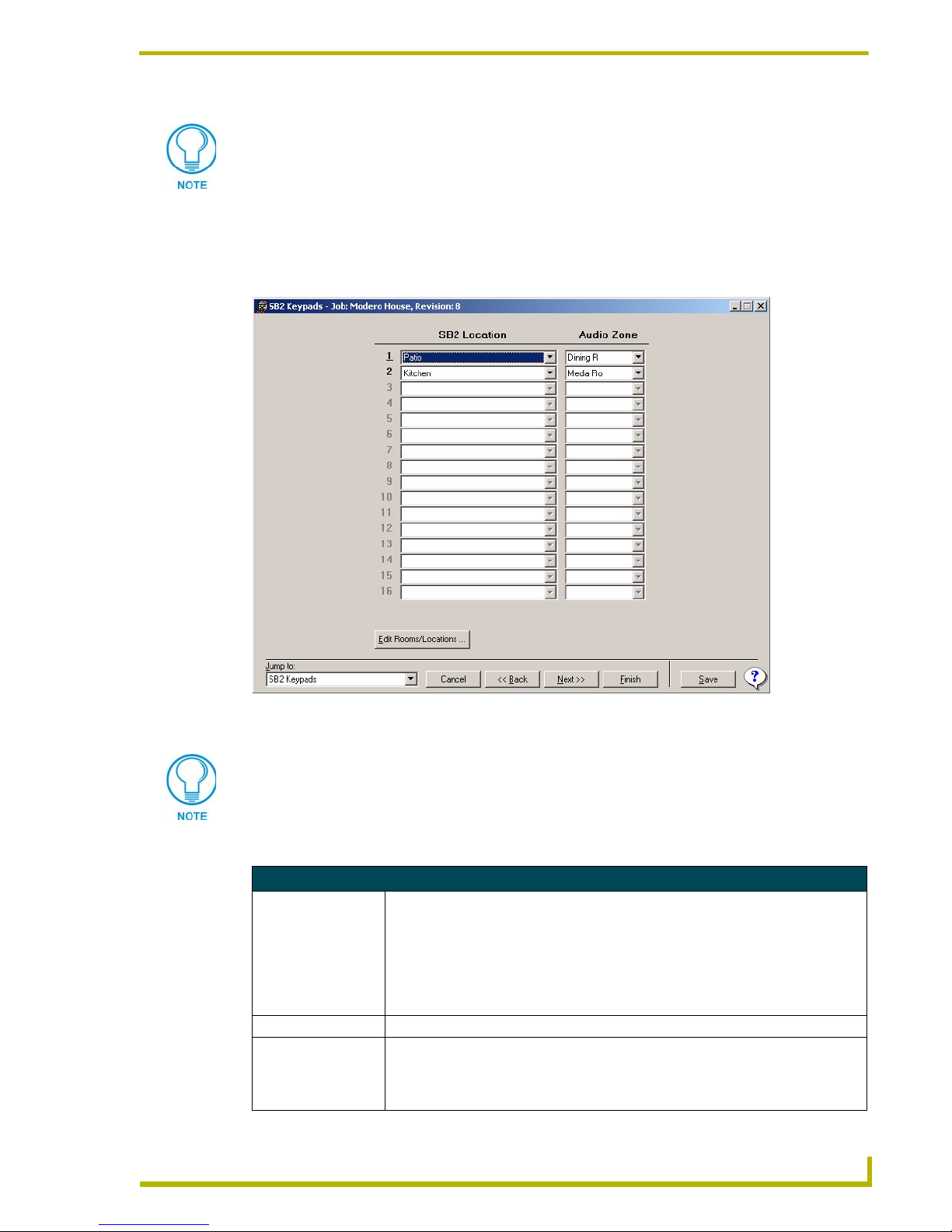
Using the Design XPress Project Wizard
Do not be alarmed if the scene label in the KPD file does not match the one you
assigned in Design XPress. The scene labels will appear on the keypads once you
download them to the Master and reboot it.
SB2 Keypads dialog
The options in the SB2 Keypads dialog (FIG. 9) allow the assignment of SB2 keypads to a room/
location and an audio zone. Design XPress can handle up to 32 SB2 keypads per system.
FIG. 9 SB2 Keypads dialog
In Design XPress, SB2 keypads are used for audio zone volume control only.
The fields in this dialog include:
SB2 Keypads dialog
SB2 Location: Select from a list of Rooms/Locations. No duplicates are allowed. Room/location
names can be added, edited or removed by clicking the Edit Rooms/Locations button.
The list is based on the Room/Location Names entered in the System Information dialog.
Note: Room/Location names are limited to 20 alphanumeric characters and can
include hyphens(-) and underscore characters (_). The first 8 characters of every room
must be unique.
Audio Zone: Select an audio zone for each SB2 from the audio zone list box.
Edit Rooms/Locations: To change or edit a room or location name, click the Edit Rooms/Locations button to
invoke the Edit Rooms/ Locations dialog.
Select the room/location name you want to edit from the list (on the right-hand side of
the dialog), manually edit the selected name in the Name field, and click OK.
esign XPress Programmer’s Guide
33
Page 40

Using the Design XPress Project Wizard
Configuring SB2 Keypads
Use the SB2 Keypads dialog to specify locations and audio zones for up to 32 SB2 keypads in the
system:
1. Select a SB2 Location for each SB2 keypad in the system. The number of available SB2s in the
system is based on the number specified in the System Information dialog.
2. For each SB2 Location, select an Audio Zone.
Edit Rooms/Locations dialog
Click the Edit Rooms/Locations button in the DMS Keypads, SB2 Keypads, Door Phones or Touch
Panel Control dialogs to open the Edit Rooms/Locations dialog. Use this dialog to add, edit or
remove the Room/Location Names that were entered in the System Information dialog.
To add a Room/Location to the system, enter a name for the new Room/Location in the
Name field and click the Add button.
To change or edit a Room/Location name, select a Room/Location name from the list,
type the new name in the Name field, and click Rename.
To remove a Room/Location from the system, select a Room/Location from the list and
click Remove.
Door Phones dialog
The options in the Door Phones dialog (FIG. 10) allow the assignment of up to 4 Door Phones
(door intercom stations) to rooms/locations and audio zones in the system.
FIG. 10 Door Phones dialog
34
Design XPress Programmer’s Guide
Page 41

Using the Design XPress Project Wizard
Every door phone in the system uses two intercom zone inputs. Intercom zone inputs
are also required for DMS keypads that will utilize intercom (one per keypad).
Therefore, each door phone in the system reduces the total of allowed DMS keypads
with intercom connections by two. For example, four door phones would use eight
intercom zone inputs, leaving a maximum total of 22 DMS keypads (with intercoms)
in the system, based on the max of 30 audio zones.
The elements of this dialog are described below:
Door Phones dialog
Door Phone Location: Select from a list of Rooms/Locations. The list is based on the Room/Location Names
entered in the System Information dialog. Room/location names can be added, edited
or removed by selecting the Edit Rooms/Locations button. Each Door Phone in the
system uses one room.
Note: Room/Location names are limited to 20 alphanumeric characters and can
include hyphens (-) and underscore characters (_). The first 8 characters of every
room must be unique.
Intercom Zone: Select an intercom zone for each door phone from this list.
The Intercom Zones list is based on the Audio Zones specified in the Audio Zones
dialog.
Audio Zone(s) To Call
From <Location>:
Edit Rooms/Locations: To change or edit a room or location name, click the Edit Rooms/Locations button to
The Available list indicates audio zones that are available to call from the selected
Door Phone Location. The Selected list indicates the audio zones that have been
selected to call.
• Use the single arrow button to move a selected audio zone to the Selected list.
• Use the double-arrow button to move all available audio zones.
To specify which audio zone(s) to call from this Door Phone, use the single and double
arrow buttons to add or remove Rooms/Locations from the Available list box to the
Selected list box. The single arrows move only a single selected audio zone, the
double arrows move all audio zones from one list box to the other. By default, all audio
zones in the system are included in the Selected list, so initially you only need to
remove any audio zones that you do not want to be called from this Door Phone.
Note: Design XPress will allow you to select a Door Phone as a valid zone to call, but
it will be filtered out when you press the Next button.
invoke the Edit Rooms/ Locations dialog. Select the room/location name you want to
edit from the list (on the right-hand side of the dialog), manually edit the selected
name in the Name field, and click OK.
Configuring Door Phones
Use the options in the Door Phones dialog to assign each Door Phone (door intercom station) in the
system to a room/location, and an audio zone. The audio zone is the target zone for the specified
Door Phone. To configure a Door Phone:
1. Select a Door Phone Location for the first available Door Phone in the system from the drop-
down list. The number of available Door Phones is based on the number specified in the
System Information dialog.
2. Select an Intercom Zone to associate with this Door Phone from the drop-down list. The
Intercom Zones list is based on the data entered in the Audio Zones dialog.
3. To specify which Audio Zones to call from this Door Phone, use the single and double arrow
buttons to add or remove Audio Zones from the Selected list box. The single arrows move only
a single selected Audio Zone, the double arrows move all Audio Zones from one list box to the
other. By default, all Audio Zones in the system are included in the Selected list, so initially
esign XPress Programmer’s Guide
35
Page 42
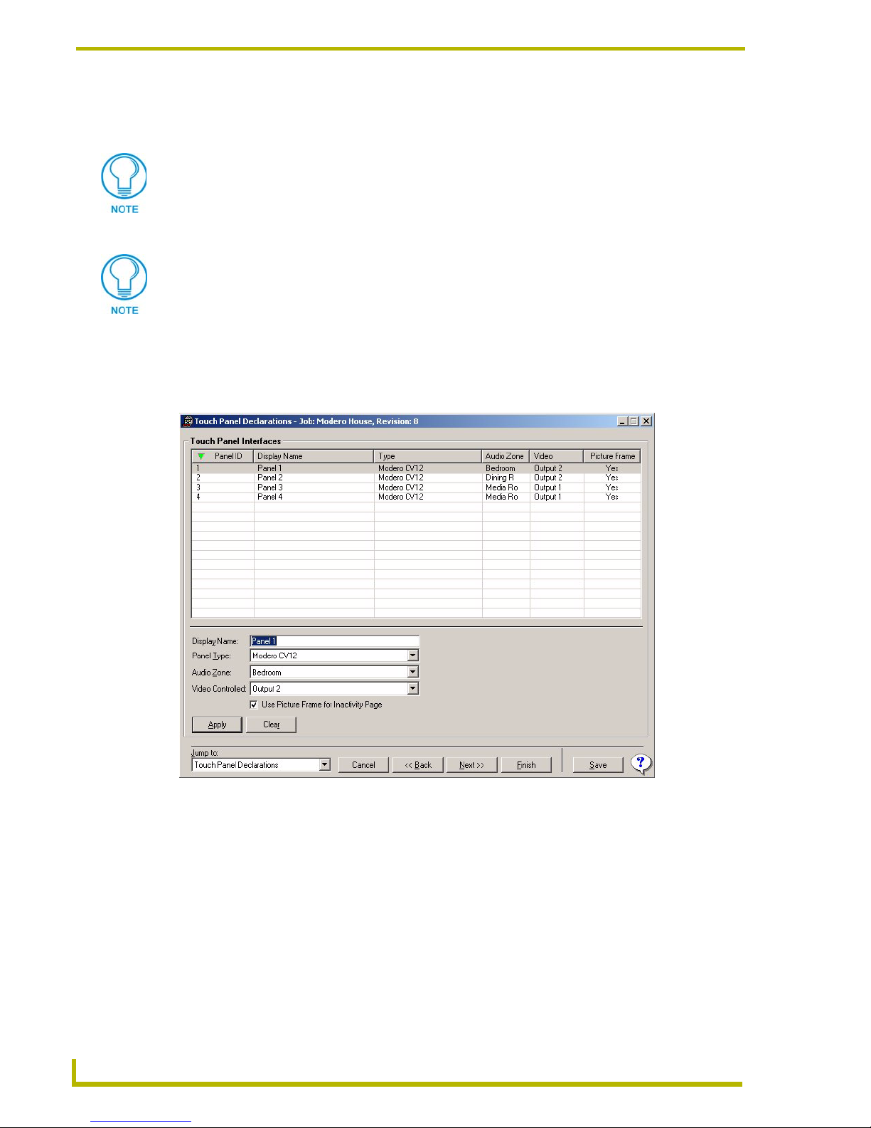
Using the Design XPress Project Wizard
you only need to remove any audio zones that you do not want to be called from this Door
Phone.
Design XPress will allow you to select a Door Phone as a valid zone to call, but it will
be filtered out when you press the Next button.
4. Repeat steps 1-3 for all remaining Door Phones in the system.
Each Door Phone in the system uses two audio zones.
Touch Panel Declarations dialog
The options in the Touch Panel Declarations dialog (FIG. 11) allow you to specify the number of
touch panels in the system, as well as the type of each panel.
FIG. 11 Touch Panel Declarations dialog
The elements of this dialog are described below:
36
Design XPress Programmer’s Guide
Page 43
Using the Design XPress Project Wizard
Touch Panel Declarations dialog
• Touch Panel Interfaces This table lists all of the touch panels currently defined in your Project (via the Touch
Panels entry in the System Information dialog. This table displays several types of
information for each panel, separated into five columns:
• Panel ID: The Panel ID is based on the number of panels specified in the System
Information dialog. This field cannot be edited in this dialog. To remove panels, or
from the Project, go to the System Information dialog.
• Display Name: The Display Name indicated here is based on the order in which
the panels were added to the project (Panel1, Panel2, etc).. You can change the
default display name by editing the Display Name text field at the bottom of this
dialog, and click the Apply button.
• Ty p e: This column displays the model number and description of each touch panel
in the list. You can change the panel type via the Panel Type drop-down list at the
bottom of this dialog (click the Apply button to save the change).
• Audio Zone: This column indicates the audio zone that each panel is associated
with. To change the audio zone for a panel, click the down arrow next to the Audio
Zone field at the bottom of this dialog and select the desired audio zone from the
drop-down list of audio zones defined in your Project, and click the Apply button.
• Video: This column displays the output of the Video Switcher (1-24) that could be
controlled by the touch panel (if the panel video-capable).
• Use PictureFrame For
Inactivity Page:
• Apply Click to apply any changes made to a selected touch panel.
• Clear Click to deselect any selected touch panel and clear the editable fields at the bottom
Click this option to use the PictureFrame application as a screensaver when the
touch panel becomes inactive. If this option is selected, you'll have to open the TP4
file created by the DXP wizard, and configure the dynamic image properties to pull
images from the PC running the PictureFrame application.
Note: If the panel timeout is set to zero, the panel will never go to the Inactivity Page.
Panel Timeout is a setting that is made directly on the touch panel (via the Setup
pages on the panel).
of this dialog.
Creating Touch Panel Declarations
Design Xpress supports up to 16 touch panels in a System. To create the touch panel declarations
for your system:
1. Select a Panel in the Touch Panel Interfaces list. The number in this column represents the
number of panels specified in the System Configuration dialog (see the System Configuration
dialog section on page 20 for details).
2. Enter a descriptive name for the panel in the Display Name text field.
Adding a New Touch Panel Interface:
1. Increase the number of Touch Panels in the system in the Touch Panels field of the System
Information dialog by one (to allow an additional Touch Panel to be defined in the Touch Panel
Declarations dialog).
2. Enter a name for the new panel in the Display Name field.
3. Select a panel type from the Panel Type drop-down list.
4. Click the Apply button to add the newly configured panel.
esign XPress Programmer’s Guide
37
Page 44

Using the Design XPress Project Wizard
Choose Background Images dialog
The options in the Choose Background Images dialog (FIG. 12) allow you to select a background
image to apply to the pages for each touch panel in the project.
FIG. 12 Choose Background Images dialog
The panel preview window contains one tab for each touch panel in the project. Use the tabs to set
background images on each panel individually:
1. Select the tab that represents the panel that you want to set the background image for.
2. Select a background from the Backgrounds list on the left side of the dialog. Several of the
backgrounds in the list have a plus sign to the left of the name (+) indicating that there are
further variations available for that theme. Click the plus sign to expand the list to show all
possible variations.
3. The preview window displays the selected touch panel page with the selected background
color scheme.
Click the All Panels the same checkbox to set the selected background on all panels in the
project (disabled by default).
38
Design XPress Programmer’s Guide
Page 45

Using the Design XPress Project Wizard
Choose Button Colors dialog
The touch panels utilize 6 button sizes. You can assign each button state (On/Off) its own color,
shape and texture using the options in the Choose Button Colors dialog (FIG. 13).
FIG. 13 Choose Button Colors dialog
There are several custom texture/shape palettes available to choose from. To access these palettes,
use the navigation window on the left-hand side of this dialog. Under the main folder Images are
several subfolders (i.e. Brushed Metal, Solid Colors, etc). Click to select any of these folders. When
these folders are selected, they automatically expand to show the two shape options available for
each texture type (Rectangle and Rounded).
Select a texture: Click to select one of the four available button textures (i.e. Brushed
Metal, Cloth Satin Swirl, etc.)
Select a shape: Click to select one the shape options contained within each of the texture
folders (i.e. Rectangular or Rounded). If no shape option is selected the button retains its
default shape.
Select a color: Click a color sample, then drag and drop it in either the Off State or
On State window. To set all buttons in either state to the same color, drag and drop the
color sample on the Drag here to replace all button.
Preview Buttons: Once you have made your color assignments, click on Preview
Buttons to invoke the <panel type> Buttons Preview dialog, which shows you a
simulation of the currently active buttons in action. In the Buttons Preview dialog, move
the mouse cursor over the buttons to see their On and Off state color assignments.
Click the All Panels the same checkbox to set the selected button colors on all panels in
the project (disabled by default).
esign XPress Programmer’s Guide
39
Page 46
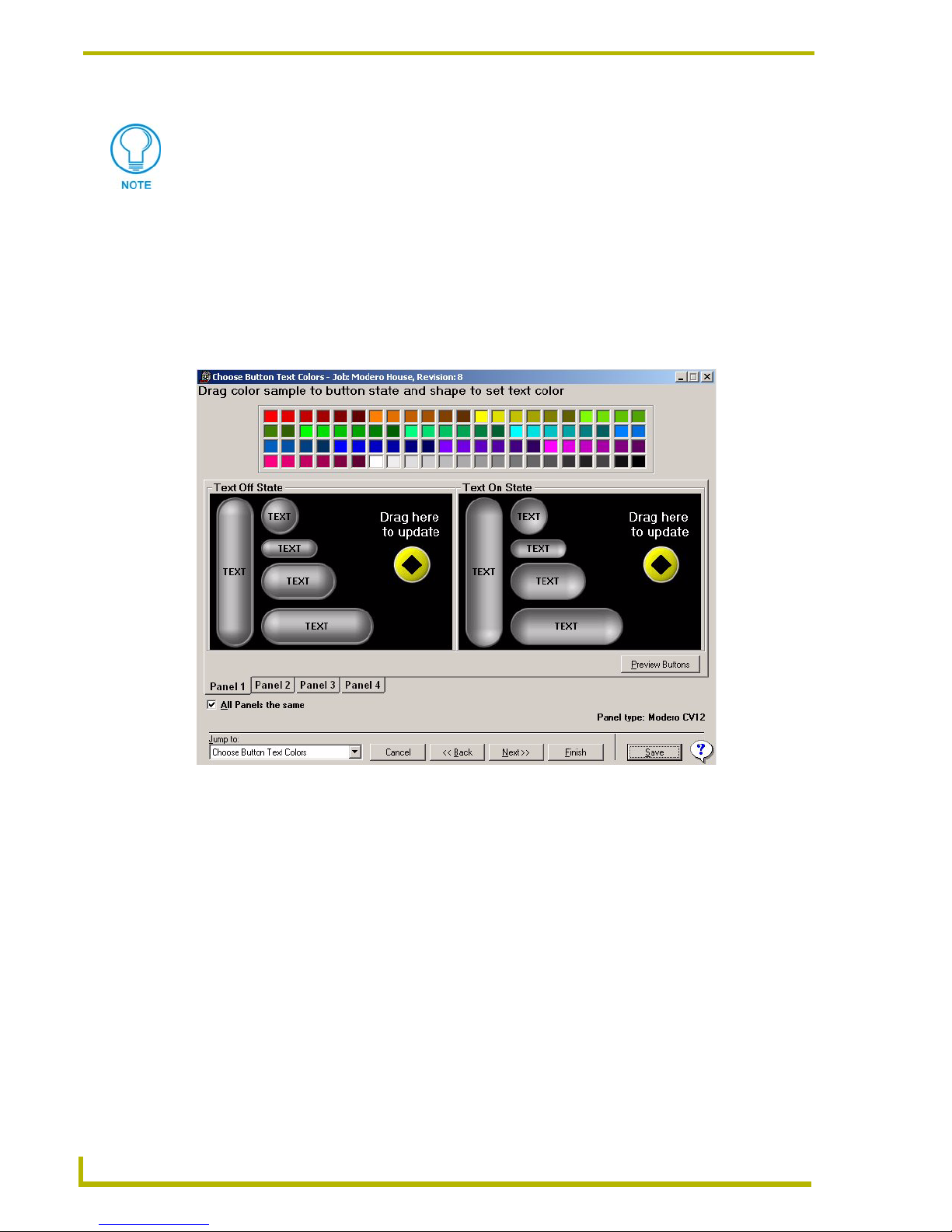
Using the Design XPress Project Wizard
Once you have assigned a texture/shape/color to the buttons, you can hover the
cursor over any button to view the button color assignment (as a tool tip).
Choose Button Text Colors dialog
You can set the button text color for each state of the button (on/off), via the options in the Choose
Button Text Colors dialog (FIG. 14).
The tabs in this dialog allow you to set a button text color scheme for each panel individually.
Conversely, the All panels the same option allows you to apply the same button text color scheme to
all panels in the project (disabled by default).
FIG. 14 Choose Button Text Colors dialog
Click a color sample in the palette, then drag and drop it to a button state.
To set all button text (in either state) to the same color, drag and drop the color sample on
the Drag here to replace all TEXT button.
40
Design XPress Programmer’s Guide
Page 47
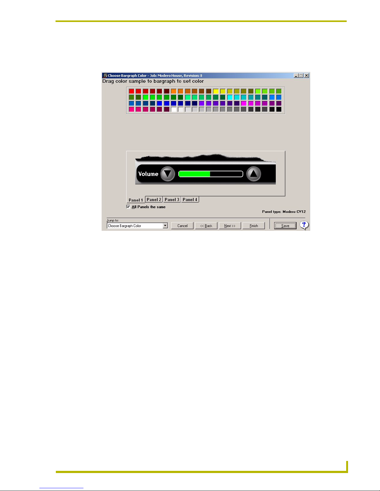
Using the Design XPress Project Wizard
Choose Bargraph Color dialog
The options in the Set Bargraph Color dialog (FIG. 15) allow you to specify a color for bargraphs.
FIG. 15 Choose Bargraph Color dialog
The tabs in this dialog allow you to set the bargraph color for each panel individually. Conversely,
the All panels the same option allows you to apply the same bargraph color to all panels in the
project (disabled by default).
Click a color sample in the palette, then drag and drop it on the bargraph image.
esign XPress Programmer’s Guide
41
Page 48

Using the Design XPress Project Wizard
Touch Panel Control dialogs
Design XPress can assign up to 16 touch panels in a system. Each touch panel included in the
system must have its location, audio and lighting zones assigned. This assignment is done on the
Touch Panel Control dialog (FIG. 16). There is one Touch Panel Control dialog for each touch
panel in the system (based on the number of touch panels specified in the System Information
dialog), and each Touch Panel Control dialog is identical.
FIG. 16 Touch Panel Control dialog
The following is a list of fields in the Touch Panel Control dialog and their descriptions:
Touch Panel Control dialog
• 1st Room Identifier Click the down arrow to display a listing of all the rooms that have been specified in
your project (via the System Information dialog). Select a room from the list as the
first controlled room associated with this touch panel.
• 2nd Room Identifier Select a room from the list as the second controlled room associated with this touch
• Edit Rooms/Locations This button allows maintenance of the Rooms/Locations list via the Edit Rooms/
• Lighting Control The touch panel can control lighting for up two rooms. Select the rooms from the 1st
panel.
Locations dialog.
and 2nd Room Identifier list boxes. If the lighting for only one room is to be controlled, select the room to be controlled in the 1st Room Identifier box and select
"--None-- " from the other list box.
The Lighting Control section for each room (up to 2) controlled by the touch panel
allows you to name and configure the lighting scenes, similar to the way it is done
for DMS keypads:
• Name: This field allows you to assign a descriptive name to each lighting scene (8
characters maximum). No duplicate lighting scene names are allowed.
• Address: This field represents the address of the lighting system or lighting
system keypad, depending upon the lighting system used.
42
Design XPress Programmer’s Guide
Page 49

Using the Design XPress Project Wizard
Touch Panel Control dialog (Cont.)
Lighting Control (Cont.) For the AMX ALD-D48, the address is always "1" (read-only).
The only valid keypad address characters are 0-9, A-F, and : (colon). For
reference, here are the formats for the various supported lighting systems:
• Lighting Control (Cont.) • Button #: The Button # refers to the button number or scene number the Design
XPress system is to emulate when communicating to the lighting system.
For AMX Radia systems, the button # is the scene number to be recalled when
this scene is selected on the touch panel.
Note: For instructions on developing NetLinx code to program scenes for the
ALD-D48, refer to AMX Tech Note # TN 543, available via www.amx.com
(Dealers > Tech Center > Tech Notes). Also refer to the ALD-D48 Network
Lighting Solution Instruction Manual for detailed configuration information.
• Copy From: The Copy from list box allows you to copy a lighting scene layout from
another touch panel or keypad in the system.
Note: If you are not controlling lighting scenes with a Touch Panel, leave these
fields blank.
Address Formats For Supported Lighting Systems
The Address and Button # fields in the House Lighting Scenes dialog correspond to either the
lighting controller address and the preset number (as with AMX Radia), or the address of the
keypad and the keypad button that will be emulated (as with the LiteTouch controller).
The only valid keypad address characters are 0-9, A-F, and : (colon).
For reference, here are the formats for the various supported lighting systems:
Lighting Controller Address Format DXP-Example
AMX ALD-D48 The Address value is fixed at a value of one and
AMX Radia AXlink Device ID (1-255).The Address is the
Clipsal C-Bus Group Address:Network Address
DynaLite DynaLite area (positive integer) 18
LiteTouch 5000LC Keypad Address (3 nibble hex value A3E
Lutron GRAFIK Eye Master (positive integer) 17
Lutron Homeworks Interactive
Lutron RadioRA Keypad Address (positive integer)Note: keypad
Vantage Qlink Master:Keypad (positive integers) 1:5
is disabled.
AXlink device ID of the Radia MC.
(network address always = zero)
Processor:Link:Keypad (positive integers) 1:4:9
address 12 is reserved as the RS-232 RadioRA
interface. This interface is a virtual keypad, and
does not contain any buttons.
1 (read-only)
96
A1:00
12
Once the application entries are completed, the touch panel files, the DMS keypad files, source
code, NetLinx Studio project file, text files (CD titles, tuner presets, etc.), and report file are all
created.
Note for ALD-D48 Lighting Systems
On the ALD-D48, each button on the touch panel or keypad corresponds to a specific lighting
preset.
esign XPress Programmer’s Guide
43
Page 50

Using the Design XPress Project Wizard
For instructions on developing NetLinx code to program scenes for the D48, refer to Tech
Note # TN 543, available via www.amx.com (Dealers > Tech Center > Tech Notes).
For detailed configuration information on the ALD-D48, refer to the ALD-D48 Network
Lighting Solution Instruction Manual, also available via www.amx.com (Dealers > Tech
Center > Tech Docs > Instruction Manuals).
Note for Radia Lighting Systems
On Radia lighting systems, channels 1-128 represent Radia lighting presets 1-128. If a channel is
on, then the corresponding preset is on. However, on startup NetLinx resets all channels to 0 (OFF).
Radia does not report the status of its channels when the master comes up, and consequently the
software believes the state of all of the presets is OFF. Therefore, until a preset changes in the
system, the channel states are not reported.
House Lighting Scenes dialog
Design XPress provides up to 12 whole house lighting scenes. These scenes can be activated from
any touch panel in the system. The House Lighting Scenes dialog (FIG. 17) associates the keypad
button numbers to their respective lighting scenes. Each lighting scene requires a lighting system
keypad address and button number.
FIG. 17 House Lighting Scenes dialog
The elements of the House Lighting Scenes dialog are described below:
44
Design XPress Programmer’s Guide
Page 51

Using the Design XPress Project Wizard
House Lighting Scenes dialog
Name: This field represents the name of the lighting system.
Address: This field represents the address of the lighting system or lighting system keypad depending
Button #: The Button # refers to the button number or scene number the Design XPress system is to
upon the lighting system used (see Lighting Addresses for details).
emulate when communicating to the lighting system.
For the AMX Radia, the button number is the scene number to be recalled when this scene is
selected on the touch panel.
For Clipsal C-Bus and Dynalite systems (used primarily outside the U.S.), the button # consists of the button number plus the fade rate, separated by a semi colon. For example:
•(C-Bus): K:P:[A4:E1]:75:8 indicates network $E1, group address $A4, go to 75% at 8-
second fade rate.
• (Dynalite): K:P:[14]:12:25 indicates area #14, go to preset scene #12 at 25-second fade
rate.
Control Button Labels dialog
Use the Control Button Labels dialog (FIG. 18) to customize the text that appears on the main
control buttons for all touch panels in the system. There are seven Control Buttons that are
displayed on the touch panels (Music, Sources, Environment, Lighting, Vide o, Weather and Exit).
FIG. 18 Control Button Labels dialog
To customize the text for these buttons, just type the new text in the field next to each
button. The new text is previewed on the button images as you type.
The button text for each button is limited to 8 characters.
esign XPress Programmer’s Guide
45
Page 52

Using the Design XPress Project Wizard
CD Titles dialog
If a CD Changer has been selected on the Audio Sources dialog, the CD Titles dialog (FIG. 19) will
be shown, with the CD Changer (as specified in the Audio Sources dialog) indicated in the title bar.
Use the CD Tiles screen to add up to 400 CD titles to appear in the CD Titles list.
FIG. 19 CD Titles dialog
Adding CD titles to Design XPress can be done in two ways; manually adding each CD title or
reading the CD title from a CD placed in the CD ROM drive of your computer. The following is a
list of fields in the CD Titles dialog and their descriptions:
CD Titles dialog
Group Tabs: The tabs along the top of this page represent the discs in the CD changer,
separated into sets of 25 (up to 400). The number of CDs in the CD changer
is based on the Changer Size entry in the Audio Sources dialog. Click on
each tab to see the names for those CD locations in the changer.
Disc Display Text: Select the disc title or enter the title in the appropriate field. The numbers
Clear All Displayed Items: Click this button to clear all the CD titles in the selected group tab.
Manually add Disc to data store: Use the fields to manually add a CD title. Type the artist name and the CD
Setting to retrieve CD data from
freedb.org:
correspond to the disc number. The contents of this list are based on the CD
titles library, accessible via the CD Titles Maintenance dialog.
title in the appropriate fields.
Select the CD drive from the drop-down list to retrieve CD information for.
To add a CD title by reading the information from a CD, go to the CD ROM
drive to retrieve CD information from section and select the appropriate drive
location. Then, select the (...) button next to the disc number you wish to title.
If the disc has never been read before, Design XPress will attempt to get the
data from freeDB.org.
Note: To prevent the CD from playing when it is inserted, hold down the shift
key on the keyboard while loading the CD.
46
Design XPress Programmer’s Guide
Page 53

Using the Design XPress Project Wizard
CD Titles dialog (Cont.)
Display order: Select the preferred text format for the disc display (Artist, CD Title or
CD Title, Artist).
CD Titles Maintenance dialog
Select Edit > CD Titles Maintenance to open the CD Titles Maintenance dialog (FIG. 20). Use
this dialog to create and maintain a library of CD titles to be used in any and all of your projects.
The fields and options in this dialog allow you to add, modify and delete CD Title and Artist
information, and automatically retrieve CD information from the freedb.org on-line database.
Anytime you add a CD via the CD Titles dialog in the Project Wizard, the title is also automatically
added to the library listed in this dialog. As titles are added to the library, they become available to
be added to any future projects.
As titles are deleted from the library via this dialog, they are removed from any projects that are
using them (Design XPress prompts you first before the file is deleted).
FIG. 20 CD Titles Maintenance dialog
Adding a new CD title
Manually enter either Artist or CD Title information to enable the Add button. Click the
Add button to add the new CD to the list.
Alternatively, you can select an existing CD title from the list, then edit the Artist and CD
Title information, and click the Add as New button.
esign XPress Programmer’s Guide
47
Page 54

Using the Design XPress Project Wizard
Editing CD Information
Select a CD title from the list to populate the Artist and CD Title fields, where you can enter new
information as desired. Click the Update button to update that CD in the list.
Retrieving CD Information (from freedb.org)
1. Insert a CD into the CD player on your PC.
To prevent the CD from playing when it is inserted, hold down the shift key on the
keyboard while loading the CD.
2. Click the down-arrow (in the Setting to receive CD data from freedb.org section of the dialog)
to view a list of available CD drives on your PC.
3. Select the drive that you placed the CD in, and click the Retrieve CD Data from CD button. If
the disc has never been read before, Design XPress will attempt to download the data from
freeDB.org.
Removing a CD Title
Select any CD in the list (Shift + click to select multiple CD Titles), and click the Delete button to
remove the CD(s) from the list.
In order for the Disc Display Text to be displayed on the Touch Panels, the text
information must be FTP’d to the System’s NetLinx Master. See the Transferring
Preset Button Text to the Master via FTP section on page 54 for details.
DSS TV Favorites dialog
Up to 22 DSS TV channels can be selected to appear in the DSS TV Favorites list on the touch
panels. The names for these channels come from the list of DSS channels selected in either the DSS
Preferences - Direct TV - TV Channels dialog (Edit > Edit DSS Channels > DirecTV > TV) or
the DSS Preferences - Dish Network - TV Channels dialog (Edit > Edit DSS Channels >
Dish Network > TV), depending on which service was specified in the System Configuration
dialog.
The numbered fields have drop-down lists containing Network titles to choose from. Select the
desired DSS TV channels from the list boxes. The order in which the channels appear in this list is
the order in which they will appear on the touch panel.
The Clear All button clears every channel.
In the Default Selections area, click the Save Current As button to save the current
favorites list as the default list. Once saved, you can quickly return to the default list by
clicking the Use button.
48
Design XPress Programmer’s Guide
Page 55

Using the Design XPress Project Wizard
FIG. 21 DSS TV Favorites dialog
Adding a New DSS TV Channel
Select Edit > Edit DSS Channels > DirecTV or Dish Network > TV to open the DSS Preferences
- TV Channels dialog, where you can add/remove and/or change the names on TV channels for
either DirecTV or Dish Network, depending on your DSS selection.
Enter a name for the new channel (in the Name field), enter the new channel number (in the
Channel field), and click the Add button. The new channel appears in the Channel list. If the
channel number is already listed, the program prompts you to verify adding the new channel, and
the new channel will overwrite the pre-existing one.
Removing a DSS TV Channel
Select a channel from the list and click Remove.
Changing the Name and/or Channel number on an Existing TV Channel
Double-click on a channel from the list to populate the Name and Channel fields with the selected
channels current information. Type the new name and/or channel numbering the Name and Channel
fields and click the Update button.
In order for the text on the DSS TV Channels buttons to be displayed on the Touch
Panels, the text information must be FTP’d to the System’s NetLinx Master. See the
Transferring Preset Button Text to the Master via FTP section on page 54 for details.
esign XPress Programmer’s Guide
49
Page 56

Using the Design XPress Project Wizard
DSS Music Favorites dialog
Up to 22 DSS Music genres (channels) can be selected to appear in the DSS Music Favorites list on
the touch panels. The names for these channels come from the list of DSS channels selected in
either the DSS Preferences - DirectTV - Music Channels dialog (Edit > Edit DSS Channels >
DirecTV > Music) or the DSS Preferences - Dish Network - Music Channels dialog
(Edit > Edit DSS Channels > Dish Network > Music).
FIG. 22 DSS Music Favorites dialog
The numbered fields have drop-down lists containing channels to choose from. Select the desired
DSS Music channel from the list boxes. The order in which the channels appear in this list is the
order in which they will appear on the touch panel.
The Clear All button clears every channel.
In the Default Selections area, click the Save Current As button to save the current
favorites list as the default list. Once saved, you can quickly return to the default list by
clicking the Use button.
In order for the text on the DSS Music Channels buttonsto be displayed on the Touch
Panels, the text information must be FTP’d to the System’s NetLinx Master. See the
Transferring Preset Button Text to the Master via FTP section on page 54 for details.
50
Design XPress Programmer’s Guide
Page 57

Using the Design XPress Project Wizard
Adding a New DSS Music Channel
Select Edit > Edit DSS Channels > DirecTV or Dish Network > Music to open the DSS
Preferences - Music Channels dialog, where you can add/remove and/or change the names on
music channels for DirecTV or Dish Network, depending on your DSS selection.
Enter a name for the new channel (in the Name field), enter the new channel number (in the
Channel field), and click the Add button. The new channel appears in the Channel list. If the
channel number is already listed, the program prompts you to verify adding the new channel, and
the new channel will overwrite the pre-existing one.
Removing a DSS Music Channel
Select a channel from the list and click Remove.
Changing the Name and/or Channel number on an Existing Music Channel:
Double-click on a channel from the list to populate the Name and Channel fields with the
selected channels current information. Type the new name and/or channel numbering the
Name and Channel fields and click the Update button.
Tuner Presets dialog
If an AM/FM Tuner has been selected on the Audio Sources dialog, the Tuner Presets dialog will be
shown, with the Tuner (as specified in the Audio Sources dialog) indicated in the title bar. Up to 24
presets can be named on the Tuner Presets dialog. This dialog allows you to assign radio station call
letters or music genre types to the preset channels (8 characters maximum).
FIG. 23 Tuner Presets dialog
esign XPress Programmer’s Guide
51
Page 58
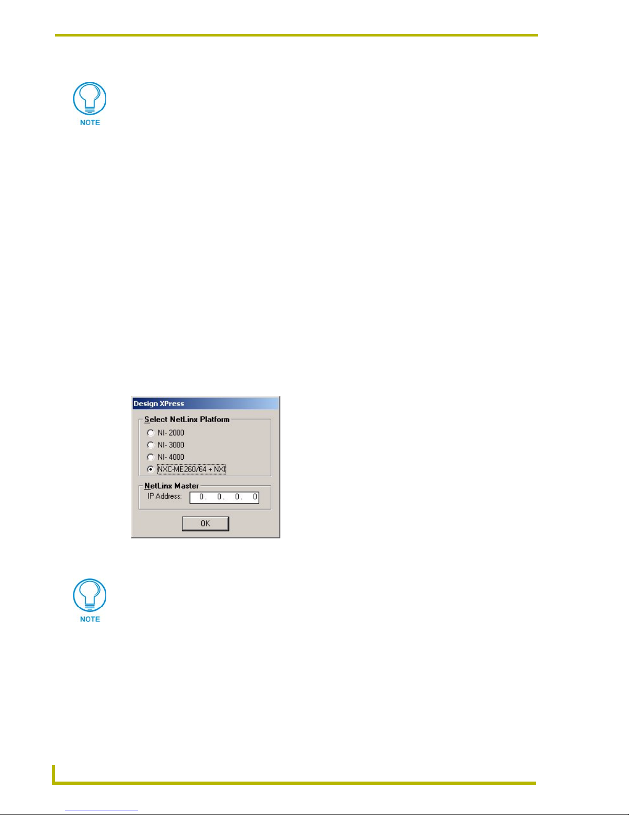
Using the Design XPress Project Wizard
Un-named presets will be displayed on the touch panel as blank buttons and can be
named directly on the touch panel.
Finishing a Project
When you have reached the final Project Wizard dialog, the Next button becomes disabled, and the
Finish button is enabled. Click the Finish button to close the Design XPress Project Wizard. At this
point, Design XPress generates the NetLinx code for the system according to your specification in
the Wizard.
1. When you click the Finish button, the Design XPress - Save As dialog appears, giving you two
save options for the project:
• Save As New Saves the project as a new revision (the current revision number is incre-
• Save As Current Saves the Project under the current revision number (no change).
• Cancel Closes the Design XPress - Save As dialog without saving the project.
2. Once you have selected a Save As option, a dialog (FIG. 24) appears prompting you to select
the NetLinx Platform (Master Controller) that will be used to control this system. The choices
are NI-2000, NI 3000, NI 4000 and NXC-ME260/64 + NXI. Some of these options may be
disabled, based on the specifications and requirements of the Project.
mented by 1).
FIG. 24 Select NetLinx Platform
The IP Address is pre-populated with data from the Preferences dialog, but you can
ebter job-specific IPs as needed.
3. Once you have selected a NetLinx Platform, click OK to compile all of the data from the
wizard and build the NetLinx Program and touch panel files.
4. When completed, a dialog is displayed indicating that the project was created successfully.
This dialog also gives you the option of viewing the project report (Report.html) and opening
the project in NetLinx Studio.
5. Click OK to save changes, close the current project and return to the Main Screen.
52
Design XPress Programmer’s Guide
Page 59

Using the Design XPress Project Wizard
The results of the Design XPress project are placed in "Projects\Job Name\Rev #", in the
application directory.
We recommend that you view and print the project report (Report.html). This report gives you
information vital to properly installing the project. This report is saved in the Projects folder of
Design XPress.
Opening the project in NetLinx Studio will allow you to download the program data and user
interface files to the NetLinx system. For more information on how to operate NetLinx Studio see
the NetLinx Studio Tutorial on the training page of the AMX web site at www.amx.com, and
consult the on-line help file and NetLinx Studio Instruction Manual (also available via
www.amx.com).
Do not be alarmed if the Lighting Scene labels in the KPD file do not match the ones
you assigned in Design XPress (House Lighting Scenes dialog). The scene labels will
appear on the keypads once you download them to the Master and reboot it.
Understanding the Report File
The report file (report.html) automatically generated by Design XPress should be used as a step-by-
step guide to installing the system.
If you choose to view the report file when the program prompts you to after finishing the project, it
is automatically opened in your default HTML viewer.
The report is broken down into the following five sections:
1. Installation Instructions
2. Device Addressing
3. Wiring/Connections
4. General Information
5. AMX Recommended Equipment List
Installation Instructions
This section of the report indicates which files need to be downloaded, and describes device
mapping, working with IR files, compile and download operations (via NetLinx Studio), and how
to reboot the NetLinx master.
Device Addressing
This section defines the device IDs of all the devices defined by Design XPress. The devices listed
in this section must be set to the given device IDs. If this is not done the system will not behave
properly. This section is divided up by device type: touch panels, DMS keypads, SB2 keypads,
HVAC, amplifiers and miscellaneous. The report details which room each device is in and what its
device ID must be set to. For example:
Keypad 1 is located in Kitchen, NetLinx address 10001:1:0
Most devices will need to have their device IDs set using NetLinx Studio. The exceptions to this are
the touch panels.
For G3 panels, device IDs must be set from the setup screen on the panel itself. Make sure when the
device ID is set that the number of devices used on the touch panel is also set. Design XPress uses 4
esign XPress Programmer’s Guide
53
Page 60

Using the Design XPress Project Wizard
devices on each touch panel. So, if the touch panel is set to use device ID 128 with 4 devices used,
that panel will actually occupy device IDs 128, 129, 130, and 131.
This does not apply to G4 panels, since their device address is set by the TPD4 file.
Wiring/Connections
This section details the locations where all of the cables will connect. It will define the connections
for all of the AMX equipment as well as the audio source equipment, IR ports, and any other
connection that must be made. Examples:
Touch Panel 1 (Study) is connected to video switcher output 1
Mom's CD is connected to NetLinx using IR port 2, IR pulse time 3/10 second
Tuner is connected to audio switcher input 1
DMS keypad 2 (Dining) connects to Mic Hub 1, PHASTlink Port 2
Mic Hub 1, line out 1 connects to audio switcher mono input 16L
Go through this section of the report one item at a time and perform each connection. Use this
section as a list of connections to make and check them off as you go.
General Information
This section of the report details the user interface file names for each touch panel and DMS
keypad, which files need to be transferred to the master, which group each audio zone is in, the
locations of each device, lighting scene addresses, file names of the generated NetLinx software,
etc.
AMX Recommended Equipment List
This section of the report lists all of the AMX equipment which will be needed to build, install, and
run the system. Both model numbers and descriptions are given to make ordering the equipment a
simple process.
Transferring Preset Button Text to the Master via FTP
Anytime that you assign text to any type of preset button in your project, you must transfer the
button text that appears on the buttons in Design XPress to the NetLinx Master, in order to display
the button text on the panel(s) in the system. This is true for CD Titles, Tuner Presets, Favorites
buttons, etc. Use File Transfer Protocol (FTP) to transfer the files.
It is recommended that you complete and then build your Project (in Design XPress)
and transfer it to the Master before you FTP the preset button text files to the Master.
To use FTP to transfer these files to the system's NetLinx Master, you'll need to know the IP
Address of the NetLinx Master:
1. Launch Windows Explorer, and navigate to the directory where your Design XPress project is
located.
2. Locate and select every TXT file in the project folder. Be sure to select every TXT file, and
only TXT files.
3. Copy the files to clipboard memory (right-click on the selection and select Copy).
4. Launch Internet Explorer.
5. In the Address box, enter FTP://, followed by the IP Address of the Master, and press Enter.
54
Design XPress Programmer’s Guide
Page 61

Using the Design XPress Project Wizard
6. Assuming the IP Address was entered correctly, and the Master is connected properly, you are
presented with a dialog prompting you to enter the User Name and Password for the Master.
The default User Name is NetLinx
The default Password is password.
7. Enter the User Name and Password, and click the Log On button. Once you are logged on to
the Master, you should see directories associated with your Design XPress project.
8. Paste the copied TXT files into the root of this directory. Do not paste them into a folder or
create a new folder for them; they must reside at the root.
Opening an Existing Design XPress Project
There are three ways to open an existing Design XPress project file. All three methods have the
same result; they each open the Project selected (highlighted) in the Project Selection list (on the
Main Screen).
First select a Project from the Project Selection List, then:
Click the Open Project button on the Main Screen
Select File > Open.
Select Open from the Project Selection List context menu.
Copying a Design XPress Project
There are three ways to copy an existing Design XPress project file under a new name. All three
methods have the same result; they allow you to rename a copy of the Project selected (highlighted)
in the Project Selection list (on the Main Screen), via the Copy Project dialog.
First select a Project from the Project Selection List, then:
Click the Copy Project button on the Main Screen
Select File > Copy.
Select Copy from the Project Selection List context menu.
Use the fields in the Copy Project dialog to specify a name for the copied project file (in the Job
Name field), and to enter a description of the project if desired (in the Description field).
The Job Name is required; the Description is optional.
Copy Project dialog
Click on the Copy Project command button (on the Main Screen) to invoke the Copy Project
dialog. Use the fields in this dialog to specify a name for the copied project file (in the Job Name
field), and to enter a description of the project if desired (in the Description field).
The Job Name is required, the description is optional.
esign XPress Programmer’s Guide
55
Page 62

Using the Design XPress Project Wizard
Importing a Design XPress Project
There are two ways to import an existing Design XPress project file into the Project Selection list.
Both methods have the same result; they each invoke the Select Import Design XPress File dialog,
where you can locate and select a Project (*.DXP) file to import.
Select File > Import Project.
Select Import from the Project Selection List context menu.
Note that importing a Project file does not affect the physical location of the imported file - it still
exists in the directory/location that you got it from, but it is now available for selection via the Main
Screen.
If you import a Project that already exists in the Project Selection List, Design XPress
automatically increments the Rev number for that Project File by one digit (as
indicated in the Rev column of the Project Selection List).
Exporting a Design XPress Project
There are two ways to export an existing Design XPress project file. Both methods have the same
result; they each invoke the Export dialog, where you can specify a name and the target directory
for the exported Project (.DXP) file.
Select File > Export Project.
Select Export from the Project Selection List context menu.
If a project is exported before deleting, you will be able to bring the project back into
Design XPress for modifications at a later date.
Deleting a Design XPress Project
There are three ways to delete an existing Design XPress project file. All three methods have the
same result; they each delete the Project selected (highlighted) in the Project Selection list (on the
Main Screen) from the hard drive. The prgram will prompt you to confirm this action, and wether to
delete it from the hardrive, or just from the DXP database.
First select a Project from the Project Selection List, then:
Click the Delete Project button on the Main Screen
Select File > Delete.
Select Delete from the Project Selection List context menu.
The program will ask you to confirm this action in the Confirm Delete Request dialog (click Yes to
delete).
If a project is not exported before deleting, you will not be able to bring the project
back into Design XPress for modifications at a later date.
56
Design XPress Programmer’s Guide
Page 63

Using the Design XPress Project Wizard
Using NetLinx Studio
Once you have created and saved a Design XPress project, typically you will then open the project
file in NetLinx Studio to download the program data and user interface files to the NetLinx system.
For more information on how to operate NetLinx Studio see the NetLinx Studio
Tutorial on the training page of the AMX web site at www.amx.com, and consult the
on-line help file and NetLinx Studio Instruction Manual (also available via
www.amx.com).
Do not be alarmed if the Lighting Scene labels in the KPD file do not match the ones you assigned
in Design XPress (House Lighting Scenes dialog). The scene labels will appear on the keypads
once you download them to the Master and reboot it.
Working With Your Project
Upon completion of the Design XPress application the next step is to use NetLinx Studio to open
the created project file. From this point on, this document will assume the installer has a good
understanding of NetLinx Studio (it can be a difficult installation if the installer is a first time
Design XPress user and a first time NetLinx Studio user).
To open the project file, use the Open Project option on the File menu and traverse to the path
where your project file resides. Once the project is open, expand all branches of the Navigator view
to see the files that have been created in the project.
There is only one file under the Source Code branch: Main.axs. This is the main file and contains
most of the system configuration information entered into the application/wizard. Other NetLinx
software files are under the Include branch of the tree. There are a lot of include files because the
software is broken up by function. For example, Lights_Dms.axi contains all software for
controlling lights via the DMS keypad. Lights_Tp.axi contains the software for controlling lights
via the touch panels. All of the touch panel and DMS keypad files are located under the User
Interface branch . The text files and report file are located under the Other branch.
To compile your project, open up the main source file and then select the Build System option
under the Build menu. Any time changes are made, the software has to be compiled.
Setting Up the Master
Some files will need to be transferred to the master outside of NetLinx Studio, using FTP (file
transfer protocol). To accomplish this, communication cannot take place over a serial cable using
the program port on the master. Instead, it must be done via Ethernet. Therefore it is always
recommended that downloads and all communication between NetLinx Studio and the master be
done via Ethernet. Using Ethernet will also make downloads quicker.
When the NetLinx master ships, it is configured for serial communication at 38,400 baud. To
configure the NetLinx master to use Ethernet communication requires a serial connection. Make
sure the correct serial port is selected and the baud rate is correct on the Master Comm Settings
page under the Tools menu. Once a connection is made, select the NetLinx Diagnostics option on
the Tools menu. Click on the Networking tab and then the Get IP Info button.
By default, the master ships with the option set to wait for a server to assign it an IP address via
DHCP. If there is no DHCP server on the network it will greatly increase startup time while the
master waits for an address to be assigned. Therefore, it is recommended that the IP address be set
to a static address. To do this, select Specify IP Address and enter the IP address you want to
esign XPress Programmer’s Guide
57
Page 64

Using the Design XPress Project Wizard
assign to the master, the subnet mask to apply, and the gateway address, if applicable. When all
entries are filled, click the Set IP Info button. The master will need to be rebooted for the changes
to take affect.
Addressing the System
The NetLinx NXI system used by Design XPress consists of two devices: the master and the NXI
(serial ports, relays, IR ports, and I/O ports). Each is addressed separately on the NetLinx bus with
a unique device ID. There is no need to modify the device ID of the master unless the system is
being installed in a multi-master system. However, the device ID of the NXI may need to be
changed. Design XPress expects this device ID to be 5001:1:0.
To modify device IDs in NetLinx the current ID must be known so it can be directly told to change
to a new device ID. To determine the current device ID of the NXI use the online tree in NetLinx
Studio to view a list of all the current online devices the master recognizes. This list will show the
device ID and the type of device. Find the one that identifies itself as "NXI", and note its device ID.
To change the device ID, select the NetLinx Diagnostics option on the Tools menu and click on the
Device Addressing tab. Make sure the Change To Device check box is selected and the Change To
System check box is not selected. In the Device To Change box enter the current device ID of the
NXI in the Device field. Enter the new device ID, 5001, in the Change To Device field. Click the
Change Device/System Number button to make the change. Your online tree should change to
reflect the new ID of the NXI.
Addressing the Devices
Each device used by Design XPress and identified in the report file must have a unique NetLinx ID.
Therefore, each device will need to be addressed so it can be properly controlled. The easiest
method for setting device addresses is to connect each device onto the bus one at a time. The online
tree in NetLinx studio can be used to quickly identify which device was just added to the system.
When a device is plugged into the bus it should display in the online tree in a matter of seconds. If a
device is unplugged from the bus it will take a little longer to disappear because the master is
constantly sampling the bus for devices. When a new device is discovered it is immediately added
to the system. However, if a device disappears from the bus, the master will give it several retries
before giving up and removing it.
By addressing devices one at a time in this fashion it is very easy to do the addressing away from
the job site (office, home, etc.). This can save time and leg work while on-site where there are
always a million other things to get done.
Once the new device shows up in the online tree, its device ID and device type is displayed. Use
this device ID to change to the new value specified in the report file. To change the device ID, select
the NetLinx Diagnostics option on the Tools menu and click on the Device Addressing tab. Make
sure the Change To Device check box is selected and the Change To System check box is not
selected. In the Device To Change box enter the current device ID in the Device field. Enter the new
device ID (as specified in the report file) in the Change To Device field. Click the Change Device/
System Number button to make the change. Your online tree should change to reflect the new
device ID (the old device ID may remain for a few seconds before disappearing).
58
Design XPress Programmer’s Guide
Page 65

Using the Design XPress Project Wizard
Downloading Software and Transferring Files
In order for the system to operate, the NetLinx program and all supporting files (touch panels, DMS
keypads, IR files, text files, etc.) must be downloaded to the master. NetLinx studio can be used for
most downloads, but any file in the Other branch of the project tree will need to be loaded on the
master using FTP (file transfer protocol).
This document assumes that the reader knows how to download files using NetLinx Studio.
Compile the main software file (main.axs) and download it to the master. Download all touch panel
files, DMS keypad files, and IR files for each audio source. Since the include files are compiled into
the main program there is no need to download them individually.
All other files such as CD titles, DSS favorites, and tuner presets must be downloaded using an FTP
program. There are many of these available on the web, most of them freeware. Connect to the
master and download all of the required files into the root directory (top-most directory) of the
master. See the Transferring Preset Button Text to the Master via FTP section on page 54 for
details.
Once everything is downloaded, the master will require a reboot to load the new configuration.
You can use either TPDesign3 or NetLinx Studio to download touch panel files to the
panels. If you are using TPDesign3 to download, verify that all Color Optimization
options are turned off.
There are two places in TPDesign3 where bitmap optimization can be selected: The Bitmap
Manager, and the Download to Panel dialogs.
1. In the Bitmap Manager dialog (Panel > Bitmap Manager), make sure that you do not click
the Optimize button at any time that the project is open. If by mistake you optimize the bitmaps
in your project, you must close the TPD project without saving any changes, and re-open.
2. In the Comm Settings tab of the Download to Panel dialog (accessible via the File Menu),
verify that Optimize Bitmap Colors is not selected.
There are no optimization issues when downloading via NetLinx Studio.
esign XPress Programmer’s Guide
59
Page 66

Using the Design XPress Project Wizard
60
Design XPress Programmer’s Guide
Page 67

Using the Design XPress Project Wizard
esign Xpress Programmer’s Guide
61
Page 68

AMX reserves the right to alter specifications without notice at any time.
ARGENTI NA • AUS TRALIA • BELGIUM • BRAZIL • CANAD A • CHINA • ENGLAN D • FRAN CE • GERM ANY • GR EECE • HO NG KONG • INDIA • INDONE SIA • ITALY • JAPAN
LEBANON • MALAYSIA • MEXICO • NETHERLANDS • NEW ZEALAND • PHILIPPINES • PORTUGAL • RUSSIA • SINGAPORE • SPAIN • SWITZERLAND • THAILAND • TURKEY • USA
ATLANTA • BOSTON • CHICAGO • CLEVE LAND • DALLAS • DENV ER • INDIANAPOLIS • LOS ANGELES • MINNEAPOLIS • PHILADELPHIA • PHOENIX • PORTLAND • SPOKANE • TAMPA
3000 RESEARCH DRIVE, RICHARDSON, TX 75082 USA • 800.222.0193 • 469.624.8000 • 469-624-7153 fax • 800.932.6993 technical support • www.amx.com
2005 AMX Corporation. All rights reserved. AMX, the AMX logo, the building icon, the home icon, and the light bulb icon are all trademarks of AMX Corporation.
©
033-004-2662 3/05
In Canada doing business as Panja Inc.
 Loading...