

Page 1

instruction manual
AXC-TEMP
Temperature Control Card and RTS-1
Room Temperature Sensor
Axcess Control Cards
Page 2

Limited Warranty and Disclaimer
AMX Corporation warrants its products to be free from defects in material and workmanship under normal use for a
period of three years from date of purchase from AMX Corporation, with the following exceptions. Electrolumines-
cent and LCD control panels are warranted for a period of three years, except for the display and touch overlay com-
ponents which are warranted for a period of one year. Disk drive mechanisms, pan/tilt heads, power supplies,
modifications, MX Series products, and KC Series products are warranted for a period of one year. Unless otherwise
specified, OEM and custom products are covered for a period of one year. AMX Corporation software products are
warranted for a period of 90 days. Batteries and incandescent lamps are not covered.
This warranty extends to products purchased directly from AMX Corporation or an authorized AMX Corporation
dealer. Consumers should inquire from selling dealer as to the nature and extent of the dealer’s warranty, if any.
AMX Corporation is not liable for any damages caused by its products or for the failure of its products to perform,
including any lost profits, lost savings, incidental damages, or consequential damages. AMX Corporation is not liable
for any claim made by a third party or made by you for a third party.
This limitation of liability applies whether damages are sought, or a claim is made, under this warranty or as a tort
claim (including negligence and strict product liability), a contract claim, or any other claim. This limitation of liabil-
ity cannot be waived or amended by any person. This limitation of liability will be effective even if AMX Corporation
or an authorized representative of AMX Corporation has been advised of the possibility of any such damages. This
limitation of liability, however, will not apply to claims for personal injury.
Some states do not allow a limitation of how long an implied warranty lasts. Some states do not allow the limitation
or exclusion of incidental or consequential damages for consumer products. In such states, the limitation or exclusion
of the Limited Warranty may not apply to you. This Limited Warranty gives you specific legal rights. You may also
have other rights that may vary from state to state. You are advised to consult applicable state laws for full determina-
tion of your rights.
EXCEPT AS EXPRESSLY SET FORTH IN THIS WARRANTY, AMX CORPORATION MAKES NO OTHER WAR-
RANTIES, EXPRESS OR IMPLIED, INCLUDING ANY IMPLIED WARRANTIES OF MERCHANTABILITY OR FIT-
NESS FOR A PARTICULAR PURPOSE. AMX CORPORATION EXPRESSLY DISCLAIMS ALL WARRANTIES NOT
STATED IN THIS LIMITED WARRANTY. ANY IMPLIED WARRANTIES THAT MAY BE IMPOSED BY LAW ARE
LIMITED TO THE TERMS OF THIS LIMITED WARRANTY.
Page 3

Table of Contents
Table of Contents
Product Information .................................................................................................1
Features ............................................................................................................................ 1
Pre-Installation ..........................................................................................................3
Setting Fahrenheit or Celsius ............................................................................................ 3
Setting the Jumpers ................................................................................................................. 3
Calibrating POTs ............................................................................................................... 4
Connecting Multiple RTS1s............................................................................................... 4
RTS1 Preparation.............................................................................................................. 5
Wiring the RTS1....................................................................................................................... 5
RTS1 Calibration ............................................................................................................... 6
Testing the RTS1 .............................................................................................................. 7
Programming ............................................................................................................9
AXC-TEMP Temperature Control Card and RTS1 Room Temperature Sensor
i
Page 4

Table of Contents
ii
AXC-TEMP Temperature Control Card and RTS1 Room Temperature Sensor
Page 5
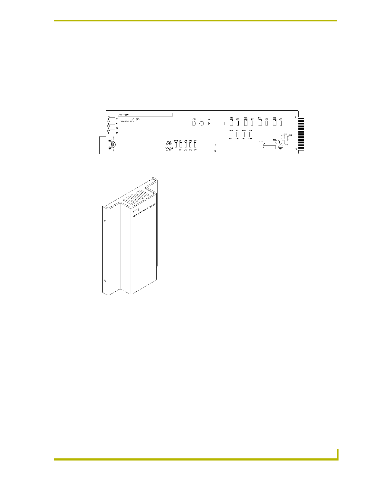
Product Information
The AXC-TEMP Temperature Control card (FIG. 1) provides control and power
for the RTS1 Room Temperature Sensor (FIG. 2). The RTS1 provides precision
temperature sensing for the AXT-TEMP.
FIG. 1 AXC-TEMP
Product Information
FIG. 2 RTS1
Features
The AXC-TEMP features include:
! Standard Axcess CardFrame slot size
! Settings for Fahrenheit or Celsius operation
! Control and power for up to four independent RTS1 units
! Measurement accuracy of +/- 2°F (+/- 1.1°C)
! Calibration for zero temperature deviation
The RTS1 features include:
! Precise temperature measurement from 5× to 128°F (-29.2× to +106.9°C)
! Connection to the AXC-TEMP card with a shielded 3-conductor cable
AXC-TEMP Temperature Control Card and RTS1 Room Temperature Sensor
1
Page 6

Product Information
The table below lists the specifications for the AXC-TEMP and RTS1.
Specifications
AXC-TEMP
Input voltage +12 to 18 VDC
Current Draw 40 mA (using four RTS1s = 75 mA)
Temperature range 0.0 ° F to +250 ° F (0.0 ° C to +106.9 ° C)
Accuracy +/-2 ° F (+/-1.1 ° C)
Resolution 10-bit (1024 steps over range)
RTS1
Weight 3.2 oz. (91 grams)
Dimensions 4.5" x 2.75" x 9" (114 mm x 70 mm x 23 mm)
Enclosure Metal, off-white finish
Resolution 10-bit (1024 steps over range)
Temperature range -20.5°F to +250°F (-29.2°C to 106.9°C)
2
AXC-TEMP Temperature Control Card and RTS1 Room Temperature Sensor
Page 7

Pre-Installation
Before installing the AXT-TEMP and RTS1, you must properly set jumpers and
potentiometers (POTs).
Setting Fahrenheit or Celsius
Set the Fahrenheit or Celsius feature by manually selecting each jumper (JP1- JP4) or by manually
selecting the RAW A/D OUTPUT jumper on the card. FIG. 3 shows the location of the jumpers and
POTs. The RAW A/D OUTPUT jumper overrides jumpers JP1 - JP4.
Pre-Installation
Channels 1 - 4
Jumpers JP1 - JP4 and
JP13 (RAW)
FIG. 3 Location of jumpers and POTs
Jumpers JP5 - JP8
Jumpers JP9 - JP12
Setting the Jumpers
Use the two-position jumpers (FIG. 4) to select Fahrenheit or Celsius operation. The setting takes
effect when you power on the system or reinsert the card into the CardFrame. The default setting is
Fahrenheit (°F).
°F
°C
JP1
FIG. 4 Jumpers
1. Set each jumper (JP1 - JP4) on the card for either Fahrenheit or Celsius.
2. Set all calibration POTs to zero. Each POT is a 25 turn POT. Full counter-clockwise is a -4°
variance and full clockwise is a +4° variance.
To access the jumper and POTs, remove the AXC-TEMP card from the CardFrame.
After making all adjustments, be sure to reseat the card properly. You can also adjust
the card using an optional Axcess Extender Card (AXC-EXTN), for easier access.
3. Insert the card into the desired Axcess CardFrame slot. It is not necessary to disconnect power
to the CardFrame when installing the card.
AXC-TEMP Temperature Control Card and RTS1 Room Temperature Sensor
3
Page 8

Pre-Installation
4. Hold the card by the tab end and slide the card into the frame. Make sure the card is correctly
positioned in the guide slot.
5. Gently push the card in until it is firmly seated in the card connector slot. It is not necessary to
disconnect the power to the CardFrame when installing the card.
Calibrating POTs
Use the four calibration potentiometers (POTs), marked CH 1 - CH 4, to adjust the respective RTS1
units 1 - 4. The default setting for each POT pointer is 0°. The table below describes the POT
calibration for CH 1 - CH 4.
Calibration POTs CH1 - CH4
POTs Description
R1 Offsets input CHAN1 by -4 to +4 degrees
R8 Offsets input CHAN 2 by -4 to +4 degrees
R2 Offsets input CHAN 3 by -4 to +4 degrees
R9 Offsets input CHAN 4 by -4 to +4 degrees
R33 Stops Adj for input CHAN 1 (for RTS2 only)
R34 Stops Adj for input CHAN 2 (for RTS2 only)
R35 Stops Adj for input CHAN 3 (for RTS2 only)
R36 Stops Adj for input CHAN 4 (for RTS2 only)
Connecting Multiple RTS1s
FIG. 5 shows the pinout for the AXC-TEMP when connecting multiple RTS1s.
PIN 1
PIN 16
FIG. 5 AXC-TEMP pinout for multiple RTS1s
GND
IN1
PWR
GND
IN2
PWR
GND
IN3
PWR
GND
IN4
PWR
TO RTS1 #1
TO RTS1 #2
TO RTS1 #3
TO RTS1 #4
4
AXC-TEMP Temperature Control Card and RTS1 Room Temperature Sensor
Page 9

Pre-Installation
RTS1 Preparation
To install the RTS1 units:
1. Wire RTS1 units 1 - 4. Refer to Wiring the RTS1 for additional information.
2. Check the temperature.
! If the panel has a display, check the temperature readings on the system Wiring control
panel. The temperature readings will change when the room temperature changes by a
half degree.
! If the panel does not have a display, check the variables in Axcess.
Wiring the RTS1
Use Belden 8723 or equivalent cable. When an application or code requires plenum-rated cable, use
Belden 88723 or equivalent cable.
Call AMX Technical Support for any installations that require a wire run of more than 100 feet.
RTS1 depth is 0.9"
(22.9 mm) with the
front cover installed
4.5"
(114.3 mm)
FIG. 6 RTS1 circuit connections
2.75" (69.9 mm)
w/ front cover on
Wire feed hole
RTS1 backplate
From left to right:
GND, OUT, PWR
AXlink connector
RTS1 circuit board
AXC-TEMP Temperature Control Card and RTS1 Room Temperature Sensor
5
Page 10

Pre-Installation
Axcess
CardFrame
AXC-TEMP
1
2
3
4
Ground Black
Drain
Green
Input White
Powe r Red
Belden 8723,
or equivalent
(Twisted Pair)
Black Ground
Drain
Green
White Output
Red Power
RTS1 Unit 1
Ground Black
5
6
7
8
9
10
11
12
13
14
15
16
FIG. 7 RTS1 to Axcess Cardframe connections
Drain
Green
Input White
Powe r Red
Ground Black
Drain
Green
Input White
Power Red
Ground Black
Drain
Green
Input White
Powe r Red
Belden 8723,
or equivalent
(Twisted Pair)
Belden 8723,
or equivalent
(Twisted Pair)
Belden 8723,
or equivalent
(Twisted Pair)
RTS1 Calibration
To calibrate the RTS1:
Black Ground
Drain
Green
White Output
Red Power
Black Ground
Drain
Green
White Output
Red Power
Black Ground
Drain
Green
White Output
Red Power
RTS1 Unit 2
RTS1 Unit 3
RTS1 Unit 4
1. Place a reference thermometer near RTS1 unit 1.
2. Allow the reference thermometer to stabilize for approximately 1-minute.
3. Adjust calibration POT R1 (CHAN 1) clockwise or counter-clockwise to match the reference
thermometer temperature.
When connecting wiring, ensure the Drain and Green wires are used. The
capacitance/filtering effects of these wires are required for accurate measurements.
4. Touch the sensor at bottom of RTS1 unit 1 for 2-seconds to force a temperature change.
5. Wait approximately 5 seconds for the temperature to stabilize. Then, recheck the display panel
temperature display. Allow the reference thermometer to stabilize approximately one minute,
then check.
6. If necessary, repeat steps 1 - 5 for RTS1 units 2 - 4, and move the reference thermometer near
each sensor you are calibrating.
6
AXC-TEMP Temperature Control Card and RTS1 Room Temperature Sensor
Page 11

Pre-Installation
Testing the RTS1
Touch the sensor at the bottom each RTS1 unit for a few seconds. The temperature on the display
panel should change. If the temperature does not change:
1. Check the wiring to each RTS1 unit that did not display a temperature change.
2. Verify the AXC-TEMP card is properly seated in the CardFrame. Repeat the steps provided in
the RTS1 Calibration section on page 6, if required.
AXC-TEMP Temperature Control Card and RTS1 Room Temperature Sensor
7
Page 12

Pre-Installation
8
AXC-TEMP Temperature Control Card and RTS1 Room Temperature Sensor
Page 13

Programming
This section provides the Axcess programming commands for the AXC-TEMP and RTS1.
! The TEMP_LEVEL variable receives data from the TEMP card (Device 16), inputs 1 - 4.
! The data is in three-digit numbers (986 = 98.6 degrees). The SEND_STRING command
to the Mini-LCD Panel converts the number to print with a decimal point.
! The 12 clears the LCD screen.
DEFINE_DEVICE
TEMP = 16
DEFINE_VARIABLE
TEMP_LEVEL1
TEMP_LEVEL2
TEMP_LEVEL3
TEMP_LEVEL4
DEFINE_START
CREATE_LEVEL TEMP,1,TEMP_LEVEL1
CREATE_LEVEL TEMP,2,TEMP_LEVEL2
CREATE_LEVEL TEMP,3,TEMP_LEVEL3
CREATE_LEVEL TEMP,4,TEMP_LEVEL4
DEFINE_PROGRAM
WAIT 10
{
SEND_STRING LCD,"12,ITOA(TEMP_LEVEL1/
10),'.',ITOA(TEMP_LEVEL1%10)"
}
Programming
A UPD command forces the card to update or send all levels to Axcess Master Card
(AXC-EM)
For additional information, refer to the Axcess Programming Language instruction manual.
AXC-TEMP Temperature Control Card and RTS1 Room Temperature Sensor
9
Page 14

AMX reserves the right to alter specifications without notice at any time.
ARGENTI NA • AUST RALIA • BELGIUM • BRAZIL • CANADA • CHINA • ENGLAND • FRANCE • GERMA NY • GREE CE • HON G KONG • INDIA • IN DONESI A • ITALY • JAPAN
LEBANON • MALAYSIA • MEXICO • NETHERLANDS • NEW ZEALAND • PHILIPPINES • PORTUGAL • RUSSIA • SINGAPORE • SPAIN • SWITZERLAND • THAILAND • TURKEY • USA
ATLANTA • BOSTON • CHICAGO • CLEV ELAND • DALLAS • DENV ER • INDIANAPOLIS • LOS ANGELES • MINNEAPOLIS • PHILADELPHIA • PHOENIX • PORTLAND • SPOKANE • TAMPA
3000 RESEARCH DRIVE, RICHARDSON, TX 75082 USA • 800.222.0193 • 469.624.8000 • 469-624-7153 fax • 800.932.6993 technical support • www.amx.com
2004 AMX Corporation. All rights reserved. AMX, the AMX logo, the building icon, th e home icon, and the light bulb icon are all trademarks of AMX Corporation.
©
031-004-1029 3/04
In Canada doing business as Panja Inc.
Last Revision: 08/03/04
 Loading...