

Page 1

Operation/Reference Guide
AXB-TC and AXB-TCR
Television Controllers (& Receivers)
Axcess Controllers
Last Revised: 7/10/2007
Page 2

AMX Limited Warranty and Disclaimer
All products returned to AMX require a Return Material Authorization (RMA) number. The RMA number is
obtained from the AMX RMA Department. The RMA number must be clearly marked on the outside of each
box. The RMA is valid for a 30-day period. After the 30-day period the RMA will be cancelled. Any shipments
received not consistent with the RMA, or after the RMA is cancelled, will be refused. AMX is not responsible
for products returned without a valid RMA number.
Warranty Repair Policy
• AMX will repair any defect due to material or workmanship issues during the applicable warranty period at no cost to the AMX
Authorized Partner., provided that the AMX Authorized Partner is responsible for in-bound freight and AMX is responsible for
out-bound ground freight expenses.
• The AMX Authorized Partner must contact AMX Technical Support to validate the failure before pursuing this service.
• AMX will complete the repair and ship the product within five (5) business days after receipt of the product by AMX. The AMX
Authorized Partner will be notified if repair cannot be completed within five (5) business days.
• Products repaired will carry a ninety (90) day warranty or the balance of the remaining warranty, whichever is greater.
• Products that are returned and exhibit signs of damage or unauthorized use will be processed under the Non-Warranty Repair
Policy.
• AMX will continue to provide Warranty Repair Services for products discontinued or replaced by a Product Discontinuance
Notice.
Non-Warranty Repair Policy
• Products that do not qualify to be repaired under the Warranty Repair Policy due to age of the product or Condition of the product may be repaired utilizing this service.
• The AMX Authorized Partner must contact AMX Technical Support to validate the failure before pursuing this service.
• Non-warranty repair is a billable service.
• Products repaired under this policy will carry a ninety (90) day warranty on material and labor.
• AMX will notify the AMX Authorized Partner with the cost of repair, if cost is greater than the Standard Repair Fee, within five (5)
days of receipt.
• The AMX Authorized Partner must provide a Purchase Order or credit card number within five (5) days of notification, or the
product will be returned to the AMX Authorized Partner.
• The AMX Authorized Partner will be responsible for in-bound and out-bound freight expenses.
• Products will be repaired within ten (10) business days after AMX Authorized Partner approval is obtained.
• Non-repairable products will be returned to the AMX Authorized Partner with an explanation.
• See AMX Non-Warranty Repair Price List for minimum and Standard Repair Fees and policies.
Page 3

Table of Contents
A
Table of Contents
AXB-TC and AXB-TCR Television Controllers .....................................................1
Overview .................................................................................................................. 1
Specifications............................................................................................................ 2
Applications.............................................................................................................. 3
Installation and Wiring ........................................................................................5
Setting the Device DIP Switch .................................................................................. 5
Internal Jumper Settings........................................................................................... 5
JI jumper settings: TV power sensing/TV power current sensing mode.......................... 6
J2 jumper settings: IR output mode (IR or serial communication) ................................... 6
J3 jumper settings: IR attenuation mode (bypass or adjustment) ................................... 6
Wiring ....................................................................................................................... 7
Wiring guidelines ............................................................................................................ 7
Preparing/connecting captive wires ................................................................................ 7
TV Sensor connections .................................................................................................... 7
IR Emitter connections .................................................................................................... 8
Axlink data and power connections ................................................................................ 8
Axlink data and 12 VDC power supply connections........................................................ 8
PCS and Axlink data and power connections .................................................................. 9
PCS and 12 VDC power supply connections ................................................................... 9
Installation .............................................................................................................. 10
Television Power Sensor Adjustment...................................................................... 11
IR Signal Attenuation Adjustment........................................................................... 11
Replacing the Lithium Battery................................................................................. 12
Programming Information ................................................................................15
Overview ................................................................................................................ 15
Channel Setting Commands.................................................................................... 15
IR Functions (Standard Order) ................................................................................ 16
Send_Commands .................................................................................................... 17
Firmware Upgrades ................................................................................................ 21
Using SOFTROM ........................................................................................................... 21
Using NetLinx Studio .................................................................................................... 22
XB-TC and AXB-TCR Television Controllers (& Receivers)
i
Page 4

Table of Contents
ii
AXB-TC and AXB-TCR Television Controllers (& Receivers)
Page 5
AXB-TC and AXB-TCR Television Controllers
A
AXB-TC and AXB-TCR Television Controllers
Overview
The AXB-TC and AXB-TCR Television Controllers are intelligent, microprocessor-controlled systems
equipped with a lithium battery to protect stored memory. The television controllers can control a variety
of Infrared-controlled devices such as televisions, audio receivers, and videocassette recorders.
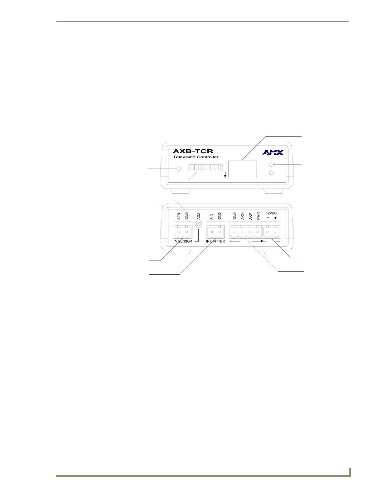
FIG. 1 shows the front and rear panels of the AXB-TCR. With the exception of the IR Input Window (on
the AXB-TCR only), the TC and TCR share the same front and rear panel components.
IR Input Window
AXlink LED
Device DIP switch
TV Power Sensing POT
TV Sensor connector
IR Emitter connector
FIG. 1 AXB-TCR front and rear panel components
AXlink
DEVICE
ON
Front
Rear
IR OUT
IR Out LED
TV Sensor LED
TV SENSOR
AXlink PWR
PWR connector
AXlink connector
XB-TC and AXB-TCR Television Controllers (& Receivers)
1
Page 6

AXB-TC and AXB-TCR Television Controllers
Specifications
The following table list the product specifications for the television controllers. Other than the IR Input
Window (on the AXB-TCR only), the specifications for the TC and TCR are identical.
AXB-TC/TCR Specifications
Dimensions (HWD):
(with connectors) • 1.29" x 3.33" x 5.54" (32.8 mm x 84.6 mm x 140.6 mm)
Power consumption: 200 mA @ 12 VDC
Front Panel Components:
LED indicators • AXlink LED (green and blinks to indicate AXlink communication activity
DEVICE DIP switch 8-position DIP switch that sets the AXlink device number on the AXB-TC
IR Input Window (AXB-TCR only) Receives 38 kHz IR-control signals from AMX transmitters.
IR Compatibility (AXB-TCR only) AMX wireless IR control panels and hand-held transmitters (38 kHz only)
Rear Panel components:
TV Sensor connector 2-pin (male) connector that supports horizontal scan frequency sensing
TV Sensor POT Sets the sensitivity to the PCS. You may need to adjust this POT to allow
IR Emitter connector 2-pin (male) connector that transmits IR control signals to a television
AXlink connector 4-pin (male) connector that supports AXlink control data communication.
PWR connector 2-pin (male) connector that connects to an external 12 VDC power sup-
Enclosure: Plastic with black matte finish
Weight: 6 oz. (170 grams)
and power:
• Full-Off indicates no power is being received or the controller is not
functioning properly.
• One blink per second indicates power is active and AXlink
communication is functioning.
• Full-On indicates there is no AXlink control or activity, but power is On.
IR Out: Red LED blinks when the television controller transmits IR or
serial (outgoing) signals.
One blink every 2 seconds: The AXB-TC/TCR program is not loaded.
TV Sensor: Red LED that lights when the television controller receives,
via the CC-IR TV Sensor, the correct horizontal scan frequency signal
indicating television or monitor power is on.
This LED also lights when the television controller receives a power on
status from an AMX PCS Power Control Sensor.
One blink every 2 seconds: The AXB-TC/TCR program is not loaded
and AXB-TCR.
The IR input window contains a red LED that lights when receiving IRcontrol data.
up to 65 kHz with a CC-IR TV Sensor. The connector can also be used
with a PCS (Power Current Sensor) to detect television power status (on
or off).
the PCS to detect the television's power status (on or off).
using the CC-IRC IR Emitter cables. The connector also supports transmitting serial control data to an external device.
ply. Refer to theWiring section on page 7 for external power supply
requirements.
2
AXB-TC and AXB-TCR Television Controllers (& Receivers)
Page 7
AXB-TC and AXB-TCR Television Controllers
A
CS
AXB-TC/TCR Specifications (Cont.)
Mounting options: Flat surface
Included accessories: • CC-IR TV Sensor (CC-XPS sensor)
• CC-IRC IR Emitter
Optional accessories: • SE-TC Security Enclosure
• PCS Power Current Sensor
• VSS2 Video Sync Sensor
• 12 VDC Power supply
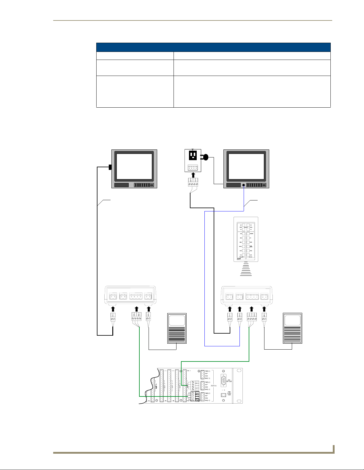
Applications
FIG. 2 shows a sample system configuration.
P
Power Control Sensor
Te l ev i s io n
Te l ev i s io n
CC-IR CC-IRC
TV Sensor/cable
AXB-TC
Power Supply
AXlink
AXlink
IR Emitter/cable
TXC-16
transmitter
IR signal
AXB-TCR
Power Supply
Axcess Cardframe (rear view)
Sample system application
FIG. 2
XB-TC and AXB-TCR Television Controllers (& Receivers)
3
Page 8

AXB-TC and AXB-TCR Television Controllers
4
AXB-TC and AXB-TCR Television Controllers (& Receivers)
Page 9
A
Installation and Wiring
Setting the Device DIP Switch
The eight-position Device DIP switch sets the identification number for the television controller. Make
sure the device number matches the number assigned in the AXCESS software program. The quick
reference table below shows the switch positions and their numeric value. In the example below, the
numeric value of the Device DIP switch is 97 (1+32+64=97).
DIP Switch Settings
Switch12345 6 7 8
Value 12 48163264128
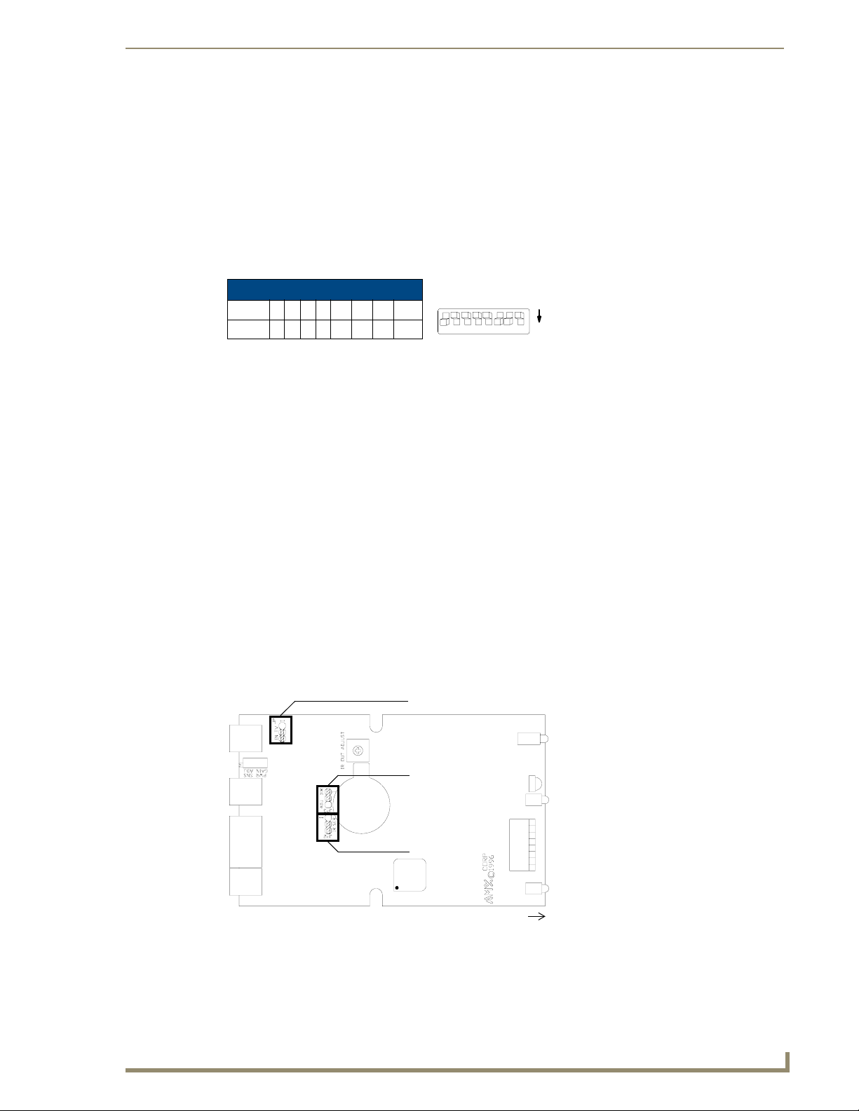
Internal Jumper Settings
The internal jumpers, located on the circuit card inside the television controller enclosure, set the input,
output, and IR attenuation modes. Internal jumper modes include:
Jumper JP1 sets the input mode for power sensing or power current sensing.
Jumper JP2 sets the IR output mode for IR or serial communication.
Jumper JP3 sets the IR attenuation mode for bypass or adjustment.
Use a Phillips-head screwdriver to open the enclosure and non-conducting pliers to set the jumpers.
DEVICE
12345678
Installation and Wiring
ON
Static electricity can damage electronic circuitry. Before removing the enclosure,
discharge any accumulated static electricity from your body by touching a grounded
metal object.
1. Unplug all connectors from the rear panel of the television controller.
2. Remove the two Phillips-head screws on the bottom of the enclosure.
3. Pull the two enclosure halves apart and set the bottom portion of the enclosure on a flat surface.
FIG. 1 shows the location of the internal jumpers.
JP1 jumper
JP3 jumper
JP2 jumper
front
FIG. 1 Internal jumper locations
4. Replace the top portion of the enclosure on the bottom portion. Then, refasten the two Phillips-head
screws.
XB-TC and AXB-TCR Television Controllers (& Receivers)
5
Page 10

Installation and Wiring
JI jumper settings: TV power sensing/TV power current sensing mode
J2 jumper settings: IR output mode (IR or serial communication)
JI Jumper Settings: TV Power Sensing/TV Power Current Sensing
Television Power Sensing mode To use this mode, connect a TVS TV Sensor
to the television to detect horizontal scan frequencies up to 65 kHz.
Place the 2-pin jumper on the JP1 connector
pin's 1 and 2.
Television Power Current Sensing mode To use this mode, connect a sensor device
(such as a PCS2 Dual Power Current Sen-
sor or VSS2 Video Sync Sensor) to the
television to detect on and off power status.
Place the 2-pin jumper on the JP1 connector
pin's 2 and 3.
J2 Jumper Settings: IR Output Mode (IR or Serial Communication)
IR Output mode To use this mode, connect a CC-IRC IR
Emitter to the television to transmit IR signals.
Place the 2-pin jumper on the JP2 connector
pin's 2 and 3.
Serial (wired connection) Output mode Place the 2-pin jumper on the JP2 connector
pin's 1 and 2.
J3 jumper settings: IR attenuation mode (bypass or adjustment)
J3 Jumper Settings: IR Attenuation Mode (Bypass or Adjustment)
IR Signal Attenuation Bypass mode (normal) Place the 2-pin jumper on the JP3 connector
pin's 1 and 2.
IR Signal Attenuation Adjustment mode Place the 2-pin jumper on the JP3 connector
Refer to the product documentation for the PCS2 Dual Power Current Sensor, VSS2
Video Sync Sensor, TVS TV Sensor and CC-IRC IR Emitter (available online at
www.amx.com) for more information on these devices.
pin's 2 and 3.
Also, set the JP2 internal jumper for IR emitter mode.
6
AXB-TC and AXB-TCR Television Controllers (& Receivers)
Page 11
Installation and Wiring
A
Wiring
The TV sensor, IR emitter, AXlink, and 12 VDC power supply connectors are located on the rear panel
of the television controller as shown in FIG. 1 on page 1.
Do not connect power directly to the television controller. If you are using power from
AXlink, disconnect the wiring from the Central Controller before connecting the wiring
to the television controller. If you are using an optional 12 VDC power supply, apply
power to the television controller only when installation is complete.
Wiring guidelines
The television controller requires 12 VDC power to operate properly. The power can be supplied via
AXlink cable, or with an optional 12 VDC power supply. The maximum wiring distance between the
Central Controller and television controller is determined by power consumption, supplied voltage, and
the wire gauge used for the cable.
The following table lists wire sizes and the maximum lengths allowable between the television controller
and Central Controller. The maximum wiring lengths are based on a minimum of
13.5 volts available at the Central Controller's power supply. If a television controller is installed farther
away from the Central Controller than recommended in the table, connect a 12 VDC power supply to the
2-pin 12 VDC PWR connector on the rear panel.
Wiring Guidelines - TC - 175 mA Wiring Guidelines - TCR - 200 mA
Wire size Maximum wiring
length
18 AWG 670.69 feet (204.43 meters) 18 AWG 586.55 feet (178.78 meters)
20 AWG 424.33 feet (129.34 meters) 20 AWG 371.29 feet (113.17 meters)
22 AWG 264.55 feet (80.63 meters) 22 AWG 231.48 feet (70.56 meters)
24 AWG 166.76 feet (50.83 meters) 24 AWG 145.91 feet (44.47 meters)
Wire size Maximum wiring
length
Preparing/connecting captive wires
Strip 0.25 inch of wire insulation off all wires.
1.
2. Insert each wire into the appropriate opening on the connector according to the wiring diagrams and
connector types described in this section.
Do not tighten the screws excessively; doing so may strip the threads and damage the connector.
TV Sensor connections
Connect the CC-IR to the TV Sensor connector, on the rear panel of the television controller, as shown in
FIG. 2 to detect horizontal scan frequencies up to 65 kHz.
TV SENSOR
connector
GND
SEN
Television
CC-IR
FIG. 2
CC-IR TV Sensor connector wiring diagram
XB-TC and AXB-TCR Television Controllers (& Receivers)
7
Page 12

Installation and Wiring
IR Emitter connections
Connect the CC-IRC IR Emitter to the IR Emitter connector, on the rear panel of the television controller
(FIG. 3) to transmit IR control signals to the television.
FIG. 3 CC-IRC IR Emitter connector wiring diagram
Axlink data and power connections
Connect the Central Controllers's AXlink connector to the AXlink connector on the rear panel of the
television controller for data and 12 VDC power, as shown in FIG. 4.
IR EMITTER
connector
CC-IRC
Television
GND
SG
12 VDC
PWR connector
PWR
GND
PWR
AXP
AXM
GND
FIG. 4 AXlink data and power wiring diagram
no connection
PWR
AXP
AXM
GND
Axcess Control SystemAXlink connector
Axlink data and 12 VDC power supply connections
Connect the Central Controller’s AXlink connector to the AXlink connector on the rear panel of the
television controller, and the optional 12 VDC power supply, as shown in FIG. 5.
12 VDC
PWR connector
PWR
GND
PWR
AXP
AXM
GND
12 VDC power supply
PWR
AXP
AXM
GND
Axcess Control SystemAXlink connector
FIG. 5 AXlink Data and 12 VDC Power Supply Connections
Use the 12 VDC power supply when the distance between the AMX system and television controller
exceeds the limits described in the Wiring Guidelines table on page 7.
8
AXB-TC and AXB-TCR Television Controllers (& Receivers)
Page 13

Installation and Wiring
A
Make sure to connect only the GND wire on the AXlink connector when using a 12
VDC power supply. Do not connect the PWR wire to the AXlink connector's PWR
opening.
PCS and Axlink data and power connections
Connect the PCS Power Current Sensor to the TV Sensor connector, on the rear panel of the television
controller (FIG. 6) to detect and control the television power status (on or off).
12 VDC
connector
Te le v is i on
Controller
FIG. 6 PCS and AXlink data and power wiring diagram
AXlink
connector
TV SENSOR
connector
PWR
GND
PWR
AXP
AXM
GND
GND
SEN
no connection
PWR
AXP
AXM
GND
PCS
Power Supply Sensor
PCS and 12 VDC power supply connections
Connect the PCS to the TV Sensor connector, on the rear panel of the television controller, and the
optional 12 VDC power supply, as shown in FIG. 7, to detect and control the television power status (on
or off).
Television
Controller
12 VDC
connector
AXlink
connector
PWR
GND
PWR
AXP
AXM
GND
PWR
GND
PWR
AXP
AXM
GND
12 VDC
power supply
PCS
Power Supply Sensor
TV SENSOR
connector
FIG. 7 PCS and optional 12 VDC power supply wiring diagram
XB-TC and AXB-TCR Television Controllers (& Receivers)
GND
SEN
9
Page 14

Installation and Wiring
Installation
Install the television controller on any flat surface or inside the optional SE-TC Security Enclosure, as
described below:
1. Mount the Axcess Central Controller where it will be used. Then, connect the power supply.
2. Route the Axlink power and data cable, CC-IR TV Sensor cable, CC-IRC IR Emitter cable, and 12
3. Drill four #6-32 holes into the SE-TC mounting surface in the locations shown in FIG. 8.
VDC power supply from the television to the television controller's location.
10
FIG. 8 SE-TC mounting dimensions
4. Mount the SE-TC.
AXB-TC and AXB-TCR Television Controllers (& Receivers)
Page 15
Installation and Wiring
A
Television Power Sensor Adjustment
After connecting the CC-IR to the television, the power sensing POT, on the rear of the television
controller (see FIG. 1 on page 1), may require adjustment to detect the television's power status:
Use a Phillips-head screwdriver and flat-blade tool (non-conducting) to adjust the POT screw.
1. Turn the television off.
2. Locate the POT screw on the circuit card and turn it clockwise 20 full turns or until it clicks. The red
TV Sensor indicator, located on the front panel, should be dark.
3. Turn the television on.
4. Turn the POT screw counterclockwise until the TV Sensor indicator lights. Then, turn the POT
screw counterclockwise one full turn.
5. Turn television power off. If the TV Sensor indicator is lit, turn the POT screw clockwise until the
indicator goes dark.
6. Reattach the enclosure and refasten the two screws.
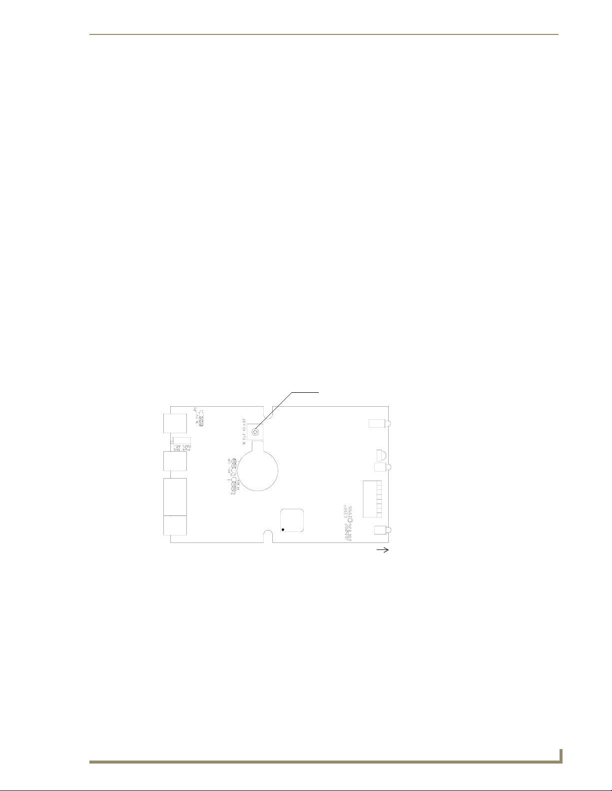
IR Signal Attenuation Adjustment
If you experience television control problems after connecting a CC-IRC IR Emitter to the television, the
television may be too sensitive to interpret the IR signals generated by the television controller. You can
use the IR signal attenuation POT, located inside the television controller (FIG. 9), to decrease the
strength of the IR signal.
Refer to Internal Jumper Settings section on page 5 to put the AXB-TC or AXB-TCR in IR attenuation
mode.
IR signal attenuation POT
front
FIG. 9 IR signal attenuation POT location
Use a Phillips-head screwdriver and flat-blade tool (non-conducting) to adjust the POT screw.
Static electricity can damage electronic circuitry. Discharge any static electricity from
your body by touching a grounded metal object before adjusting the POT.
1. Remove the two Phillips-head screws on the bottom of the television controller enclosure.
2. Pull the two enclosure halves apart and set the bottom portion of the enclosure on a flat surface.
3. Locate the POT screw on the circuit card and turn it counterclockwise with a flat-blade tool until it
stops.
XB-TC and AXB-TCR Television Controllers (& Receivers)
11
Page 16

Installation and Wiring
4. Turn the POT screw clockwise one-eighth turn to increase signal saturation. Then, send an IR
5. Send an IR control signal to the television for all programmed operations. If an operation fails, go
6. Reattach the enclosure and refasten the two screws.
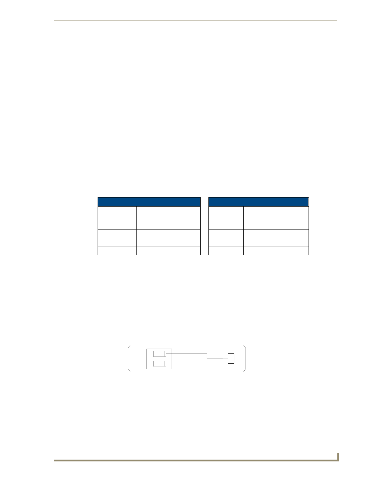
Replacing the Lithium Battery
There is a lithium battery (FIG. 10), with a life of approximately five years, in the television controller
that protects stored presets if there is a power loss. The battery is not used when DC power is supplied to
the television controller. You should write down the replacement date on a sticker or label by adding 5
years to the date of installation, and attach it to the bottom of the television controller.
FIG. 10 Lithium battery and socket
control signal to the television. If the television performs correctly, go to step 5. If not, repeat this
step until the television performs the correct operation.
back to step 4.
Battery (CR2025 type)
socket
All control commands in television controller memory are lost when the lithium battery
is replaced.
Contact your AMX dealer before you replace the lithium battery to verify that they have a current copy
of the IRLIB program file for your television controller. This will prevent any inadvertent loss of data or
service outage.
Static electricity can damage electronic circuitry. Before removing the battery from the
enclosure, discharge any static electricity from your body by touching a grounded
metal object.
Use a flat-blade tool (non-conducting) that can be slipped under the lithium battery to pry it up and out of
the socket.
1. Discharge the static electricity from your body.
2. Unplug all cables from the television controller.
3. Remove the two Phillips-head screws on the bottom of the television controller enclosure.
4. Pull the two enclosure halves apart and set the bottom portion of the enclosure on a flat surface.
5. Locate the battery on the circuit card.
6. Carefully pry the battery out of its socket and insert the new battery. Write down the next
replacement date on a label by adding 5 years to the replacement date; attach it to the bottom of the
television controller.
7. Reattach the enclosure and refasten the two screws.
8. Plug all cables back into the television controllers.
12
AXB-TC and AXB-TCR Television Controllers (& Receivers)
Page 17

A
There is a danger of explosion if you replace the battery incorrectly. Replace the
battery with the same or equivalent type, recommended by the manufacturer.
Dispose of the used battery according to the manufacturer's instructions. Never
recharge, disassemble, or heat the battery above 212 °F (100 °C). Never solder
directly to the battery or expose the contents of the battery to water.
Installation and Wiring
XB-TC and AXB-TCR Television Controllers (& Receivers)
13
Page 18

Installation and Wiring
14
AXB-TC and AXB-TCR Television Controllers (& Receivers)
Page 19

A
Programming Information
Overview
The television controllers are controlled with channel settings, IR functions, and Axcess
Send_Commands. You create software programs with the AMX Axcess programming software. Use the
programming information in this section with the Axcess Programming Guide to program television
controllers. After you create the IRLIB program, download it to the non-volatile (battery protected)
memory in the television controller. Refer to the IRLIB Infrared Library Management Program
instruction manual to create and store IR control files.
Channel Setting Commands
Use the channel setting commands listed in the following table to generate IR code, PUSH and
RELEASE operations, and to detect power failure errors.
Channel Setting Commands
ChannelDescription
1-127 Channels that generate IR code for the corresponding functions.
128-247 PUSH and RELEASE channels for received IR code.
248 A PUSH on this channel generates a power failure error.
249 Red IR sensor (AXB-TCR only) LED blinks when channel 249 and 250 are on.
250 Red IR sensor (AXB-TCR only) LED lights when channel is on.
255 Channel is on, when the television power sensor (CC-IR) detects a horizontal scan frequency. The
channel is disabled after the television controller receives a 'POF' (power off) or 'PON' (power on)
command. The channel is enabled after the television controller receives a 'POD' (disable 'PON' or
'POF') command.
Programming Information
If one of these channels is turned on while another is already on, the initial channel
stops transmitting and the second channel begins.
XB-TC and AXB-TCR Television Controllers (& Receivers)
15
Page 20

Programming Information
IR Functions (Standard Order)
The following table lists the IR function, in their standard order.
IR Functions (Standard Order)
FunctionDescription FunctionDescription
1 play > 22 channel up or +
2 stop [] 23 channel down or -
3 pause | | or still 24 volume up or +
4 ffwd >> 25 volume down or -
5 rewind << 26 mute
6 search fwd >>| (AMS music search fwd for
7 search rev |<< (AMS music search rev for CD) 28 off (power typically)
8 record 29 TV/Video, TV/VCR, or TV/LDP (one
9 power or on/off 30 TV
10 '0 ' or '10 ' 31 Video1, Line A, VCR1, VDP, or input +
11 '1 ' (channel digits or tracks for CD) 32 Video2, Line B, VCR2, or input -
12 '2 ' 33 Video3
13 '3 ' 34 RGB1 or Tape1
14 '4 ' 35 RGB2 or Tape2
15 '5 ' 36 CD
16 '6 ' 37 tuner
17 '7 ' 38 phono
18 '8 ' 39 aux
19 '9 ' 40 AM/FM
20 '+10 ' (for CD players typically) 41 play < (play reverse)
21 enter (typically used in conjunction with num-
27 on (power typically)
CD)
button source selection)
42 A/B
bers)
16
AXB-TC and AXB-TCR Television Controllers (& Receivers)
Page 21

Programming Information
A
Send_Commands
Use the Send_Commands listed in the following table to program the Axcess Central Controller and
television controller.
The device number range for the television controller is 1 through 255.
Refer to the Axcess Programming Language instruction manual for additional programming
information.
Send_Commands
CARON Enables an IR carrier signal after receiving a 'CARON' command.
Example:
SEND_COMMAND 1,'CARON'
Enables the carrier signal for device 1.
CAROFF Disables an IR carrier signal from responding until a 'CARON' command
is received. Use this command to control television controllers via serial
communication.
Example:
SEND_COMMAND 255,'CAROFF'
Disables the carrier signal for device 255.
'CH',<Channel> Generates IR digit pulses to select a television channel number. Chan-
nels 1-99 pulse as two digits. Channels 100 and greater, the one-hundredth digit pulses as 127. If IR function 21 (enter) exists, it follows the
IR digit pulses.
Variable:
<Channel> = 0-199
Example:
SEND_COMMAND 2,"'CH',25"
Sets the television connected to device 2 to channel 25.
'CTOF',<Time> Sets the single IR pulses off time between channel digits and IR func-
tions. Time is stored in permanent memory. The channel digit off time is
set with the 'CH' command and the single pulse off time is set with the
'SP' command.
Variable:
<Time> = 0-255; default = 5 (0.5 seconds)
Example:
SEND_COMMAND 3,"'CTOF',10"
Sets the off-time pulse time (delay) to 1 second for device 3.
?CTOF Sends the current off-time pulse string "'CTOF',<Time>" to the master.
Set the <Time> value in .10 second increments.
Example:
SEND_COMMAND 35,'?CTOF'
Sends the current off-time pulse string from device 35 to the master.
'CTON',<Time> Sets the IR pulse (single) on-time between channel digits and IR func-
tions. Time is stored in permanent memory. System default is 5 (.5 second). The channel digit on time is set with the 'CH' command and the
single pulse on time is set with the 'SP' command.
Variable:
<Time> = 0-255; default = 5 (0.5 seconds)
Example:
SEND_COMMAND 92,"'CTON',20"
Sets the on-time pulse (delay) to 2 seconds for device 92.
XB-TC and AXB-TCR Television Controllers (& Receivers)
17
Page 22

Programming Information
Send_Commands (Cont.)
?CTON Sends the current on-time pulse string "'CTON',<Time>" to the master.
'DC',<IR in>,<IR out> Sets a direct connection so the <IR out> (IR function) data transmits
'DE',<Time> Sets the delay time in .10 second increments for the TV sensor (CC-IR)
?DE Sends the current television power sensor (CC-IR) delay time string
DK Deletes all direct connections set with the 'DC' command.
POD Disables current 'PON' (power on) or 'POF' (power off) command set-
POF Sends IR function 28 (if available) or 9 to turn device power off. After
PON Sends IR function 27 (if available) or 9 to turn device power on. After
Set the <Time> value in .10 second increments.
Example:
SEND_COMMAND 92,'?CTON'
Sends the current on-time pulse string from device 92 to the master.
while the <IR in> code is received. The PUSH and RELEASE for the
<IR in> code is not sent to the master. The maximum number of direct
connections is 16.
Variables:
<IR in> = Custom IR function assigned to hand-held IR transmitting
device
<IR out> = IR functions (see theIR Functions (Standard Order) table
on page 16)
Example:
SEND_COMMAND 26,"'DC',145,24"
Increases the volume level on the equipment connected to device 26.
to stabilize before sensing for a status change.
Variable:
<Time> = 0-255; System default time = 10 (1 second).
Example:
SEND_COMMAND 25,"'DE',10"
Sets the delay time to 1 second for the CC-IR connected to device 25.
"'DE',<Time>" to the master.
Set the <Time> value in .10 second increments.
Example:
SEND_COMMAND 25,'?DE'
Device 25 sends the current television power sensor delay time to the
master.
tings. Channel 255 changes are enabled.
three attempts, if the CC-IR (TV sensor) still detects a power-on status,
the television controller starts processing stored buffer commands.
Then, if another IR function 28 or 9 fails to turn the television's power off,
the television controller sends a PUSH and RELEASE to channel 248
and generates a power failure error. If the device is turned on manually,
this command turns television power off unless the television controller
receives a 'PON' (power on) or 'POD' (disable 'POF') command.
three attempts, if the TV sensor (CC-IR) still detects a power-off status,
the television controller starts processing stored buffer commands.
Then, if another IR function 27 or 9 fails to turn the television's power on,
the television controller sends a PUSH and RELEASE to channel 248
and generates a power failure error. If the device is turned off manually,
this command turns television power on unless the television controller
receives a 'POF' (power off) or 'POD' (disable 'PON' command) command.
18
AXB-TC and AXB-TCR Television Controllers (& Receivers)
Page 23

Programming Information
A
Send_Commands (Cont.)
'PTOF',<Time> Sets the IR power-off pulse time after a power-on pulse in increments of
?PTOF Sends the current IR power-off pulse time string "'PTOF', <Time>" to the
'PTON',<Time> Sets the IR power-on pulse time in increments of .10 seconds. Time is
?PTON Sends the current IR power-on pulse time string "'PTON',<Time>" to the
'RO',<Offset> Sets the offset value subtracted from the IR function before sending the
'SP',<IR out> Generates a single <IR out> function pulse. The 'CTON' (pulse on) and
.10 seconds. Time is stored in permanent memory.
Variable:
<Time> = 0-255; System default = 15 (1.5 seconds).
Example:
SEND_COMMAND 55,"'PTOF',15"
Sets the power-off pulse time after a power-on pulse to 1.5 seconds for
device 55.
master. Set the <Time> value in .10 second increments.
Example:
SEND_COMMAND 55,'?PTOF'
Sends the current IR power-off pulse time from device 55 to the master.
stored in permanent memory.
Variables:
<Time> = 0-255; System default = 5 (.5 second).
Example:
SEND_COMMAND 233,"'PTON',20"
Sets the IR power-on pulse time (delay) to 2 seconds for device 233.
master. Set the <Time> value in .10 second increments.
Example:
SEND_COMMAND 233,'?PTON'
Sends the current IR power-on pulse time from device 233 to the master.
code to the master.
Variables:
<Offset> = 0-255
Example:
SEND_COMMAND 62,"'RO',5"
Subtracts 5 from the incoming IR code number and sends the appropriate IR function from device 62 to the master.
'CTOF' (pulse off) commands set the pulse time.
Variable:
<IR out> = 1-127 (see theIR Functions (Standard Order) table on
page 16)
Example:
SEND_COMMAND 225,"'SP',25"
Decreases the volume level on the equipment connected to device 255.
XB-TC and AXB-TCR Television Controllers (& Receivers)
19
Page 24

Programming Information
Send_Commands (Cont.)
XCHM
Changes the IR output pattern for
the XCH command.
XCH <Channel> Transmit the IR code in the format set with the XCHM mode command.
Syntax:
SEND_COMMAND <DEV>,'XCH-<Mode>'
Variable:
Mode = 0-4
Example:
SEND_COMMAND IR_1,'XCH 3'
Sets the IR_1 device's extended channel command to mode 3.
Mode 0 Example (default): [x] [x] <x> <enter>
SEND_COMMAND IR_1, 'XCH 3'
Transmits the IR code as 3-enter.
SEND_COMMAND IR_1, 'XCH 34'
Transmits the IR code as 3-4-enter.
SEND_COMMAND IR_1, 'XCH 343'
Transmits the IR code as 3-4-3-enter.
Mode 1 Example: <x> <x> <x> <enter>
SEND_COMMAND IR_1, 'XCH 3'
Transmits the IR code as 0-0-3-enter.
SEND_COMMAND IR_1, 'XCH 34'
Transmits the IR code as 0-3-4-enter.
SEND_COMMAND IR_1, 'XCH 343'
Transmits the IR code as 3-4-3-enter.
Mode 2 Example: <x> <x> <x>
SEND_COMMAND IR_1, 'XCH 3'
Transmits the IR code as 0-0-3.
SEND_COMMAND IR_1, 'XCH 34'
Transmits the IR code as 0-3-4.
SEND_COMMAND IR_1, 'XCH 343'
Transmits the IR code as 3-4-3.
Mode 3 Example: [[100][100]…] <x> <x>
SEND_COMMAND IR_1, 'XCH 3'
Transmits the IR code as 0-3.
SEND_COMMAND IR_1, 'XCH 34'
Transmits the IR code as 3-4.
SEND_COMMAND IR_1, 'XCH 343'
Transmits the IR code as 100-100-100-4-3.
Syntax:
SEND_COMMAND <DEV>,'XCH <Channel>'
Variable:
<Channel> = 0 through 999
20
AXB-TC and AXB-TCR Television Controllers (& Receivers)
Page 25

Programming Information
A
Firmware Upgrades
Firmware upgrades allow you to install the latest available operating system for your AXB-TC or AXBTCR. The firmware reload is required anytime the unit's LEDs all flash at the same rate as the AXlink
LED, or if all LEDs are full-on.
To accomplish the upgrade, your computer must be connected to the Axcess Master Controller via a
serial (RS-232) interface connecting to the AXlink DB-9 programming port input.
There are two ways to upgrade the firmware to an Axcess device: via the DOS-based SOFTROM
application, or via the NetLinx Studio program. Both are included on the AMX Software Control Disc.
Using SOFTROM
To be able to download new firmware, the communications settings must be set by following the steps
below.
1. Press F1 and the CONFIGURE BAUD RATE window appears (FIG. 1).
FIG. 1 CONFIGURE BAUD RATE window
2. Using the up/down arrow keys, select the communications port you are using to interface with the
Central Controller and press Enter.
3. Using the right arrow key, move to the BAUD RATE column. Then use the up/down arrow keys to
select the interface communications speed. Make sure that the BAUD RATE selections match the
settings on the Axcess System Master Controller.
4. Press Enter.
5. Press F10 to save the selected setting and to exit the CONFIGURE screen.
After establishing the communications configuration, upgrade firmware as follows:
1. Press F5 to acquire the list of online programmable devices.
2. Using the up/down arrow keys, select your firmware version(s) listed in the Firmware column of the
screen and press Enter.
3. Using the Tab key, switch to the ONLINE PANELS list.
4. Using the up/down arrow keys, select the device(s) to be programmed. Press Enter for each device
as it is selected.
F2 can be pressed to select all ONLINE PANEL devices and F3 can be pressed to
clear all devices.
5. Press F4 to program the selected device(s), the loading status bar in FIG. 2 then appears.
6. Press F5 to refresh the screen. Verify that all selected panels have the correct firmware version. If
any devices still indicated the old version, repeat preceding steps 3 through 5 until all panels
indicate the correct firmware version.
XB-TC and AXB-TCR Television Controllers (& Receivers)
21
Page 26

Programming Information
Fi
7. Upon completion of the upgrade, press F10 to exit SOFTROM.
FIG. 2 Loading status bar
rmware
Device Number
Version Number
Type Number
Loading status and device number
Firmware can be downloaded to multiple device numbers automatically. If multiple devices are selected,
the bottom half of the loading bar will indicate the percentage complete for the selected devices.
Using NetLinx Studio
You can perform firmware upgrades for both Axcess and NetLinx devices using the options in the
Firmware sub-menu.
Axcess Master Controllers use .TSK files for firmware upgrades.
1. Choose Tools > Firmware > Axcess Firmware to open the Axcess Firmware Download dialog.
2. Adjust the Comm Settings, if necessary:
a. Click Settings to open the Communication Setting dialog.
b. Select the Communications Port to use.
c. Click OK to accept the changes and return to the Axcess Firmware Download dialog.
3. Click Browse to navigate to the directory containing the firmware file(s). Once a directory
containing one or more .TSK files is specified, a list of available .TSK files is displayed in the upper
table in this dialog.
4. Select the desired .TSK file from the list.
5. Click Query Online Devices to populate the on-line device list.
6. Select the target AXlink device from the list of online devices in the lower table.
7. Click Download to open the Confirm Communication Settings dialog, where you can review and
confirm your Comm Settings and Target Device information before the download begins.
Click Cancel to return to the Select Axcess Firmware File dialog, to edit these settings (if
necessary).
Click OK to confirm the Comm Settings and Target Device information, and download the
selected .TSK file to the specified Master, on the selected communications port.
8. The File Transfer dialog shows the progress of the download. Click Cancel to cancel the download.
22
AXB-TC and AXB-TCR Television Controllers (& Receivers)
Page 27

Programming Information
A
9. Once the .TSK file has been downloaded, the program prompts you to reboot the Axcess Master.
Click Ye s to reboot, and the program initiates the reboot sequence. When the Master has rebooted,
the Status LED on the front panel of the Master blinks once a second to indicate it is functioning
properly.
10. Once it has rebooted, click OK.
XB-TC and AXB-TCR Television Controllers (& Receivers)
23
Page 28

It’s Your World - Take Control™
3000 RESEARCH DRIVE, RICHARDSON, TX 75082 USA • 800.222.0193 • 469.624.8000 • 469-624-7153 fax • 800.932.6993 technical support • www.amx.com
2007 AMX. All rights reserved. AMX and the AMX logo are registered trademarks of AMX. AMX reserves the right to alter specifications without notice at any time.
©
7/07
 Loading...