

Page 1
instruction manual
AXB-PCCOM
AXlink to PC Communications Port
Interface
AXlink Bus Controllers
Page 2

AMX Limited Warranty and Disclaimer
AMX Corporation warrants its products to be free of defects in material and workmanship under normal use for
three (3) years from the date of purchase from AMX Corporation, with the following exceptions:
• Electroluminescent and LCD Control Panels are warranted for three (3) years, except for the display and touch
overlay components that are warranted for a period of one (1) year.
• Disk drive mechanisms, pan/tilt heads, power supplies, MX Series products, and KC Series products are
warranted for a period of one (1) year.
• Unless otherwise specified, OEM and custom products are warranted for a period of one (1) year.
• Software is warranted for a period of ninety (90) days.
• Batteries and incandescent lamps are not covered under the warranty.
This warranty extends only to products purchased directly from AMX Corporation or an Authorized AMX Dealer.
AMX Corporation is not liable for any damages caused by its products or for the failure of its products to perform.
This includes any lost profits, lost savings, incidental damages, or consequential damages. AMX Corporation is not
liable for any claim made by a third party or by an AMX Dealer for a third party.
This limitation of liability applies whether damages are sought, or a claim is made, under this warranty or as a tort
claim (including negligence and strict product liability), a contract claim, or any other claim. This limitation of
liability cannot be waived or amended by any person. This limitation of liability will be effective even if AMX
Corporation or an authorized representative of AMX Corporation has been advised of the possibility of any such
damages. This limitation of liability, however, will not apply to claims for personal injury.
Some states do not allow a limitation of how long an implied warranty last. Some states do not allow the limitation or
exclusion of incidental or consequential damages for consumer products. In such states, the limitation or exclusion of
the Limited Warranty may not apply. This Limited Warranty gives the owner specific legal rights. The owner may
also have other rights that vary from state to state. The owner is advised to consult applicable state laws for full
determination of rights.
EXCEPT AS EXPRESSLY SET FORTH IN THIS WARRANTY, AMX CORPORATION MAKES NO
OTHER WARRANTIES, EXPRESSED OR IMPLIED, INCLUDING ANY IMPLIED WARRANTIES OF
MERCHANTABILITY OR FITNESS FOR A PARTICULAR PURPOSE. AMX CORPORATION
EXPRESSLY DISCLAIMS ALL WARRANTIES NOT STATED IN THIS LIMITED WARRANTY. ANY
IMPLIED WARRANTIES THAT MAY BE IMPOSED BY LAW ARE LIMITED TO THE TERMS OF THIS
LIMITED WARRANTY.
Page 3

Table of Contents
Table of Contents
Product Information .................................................................................................1
Specifications .................................................................................................................... 2
DIP Switches ..................................................................................................................... 2
Communication Parameters..................................................................................................... 2
Device Code............................................................................................................................. 3
Connectors ........................................................................................................................ 4
Preparing/connecting captive wires ......................................................................................... 4
Using the AXlink connector for data and power ....................................................................... 4
Using the RS-232 (DB-9) connector control or data ................................................................ 5
Programming ............................................................................................................7
Requests ........................................................................................................................... 7
Request Commands ................................................................................................................ 7
Send_Commands .................................................................................................................... 9
Response Commands............................................................................................................ 10
Response Mask ..................................................................................................................... 11
Axcess Master Mode....................................................................................................... 11
AXB-PCCOM Communications Port Interface
i
Page 4

Table of Contents
ii
AXB-PCCOM Communications Port Interface
Page 5
Product Information
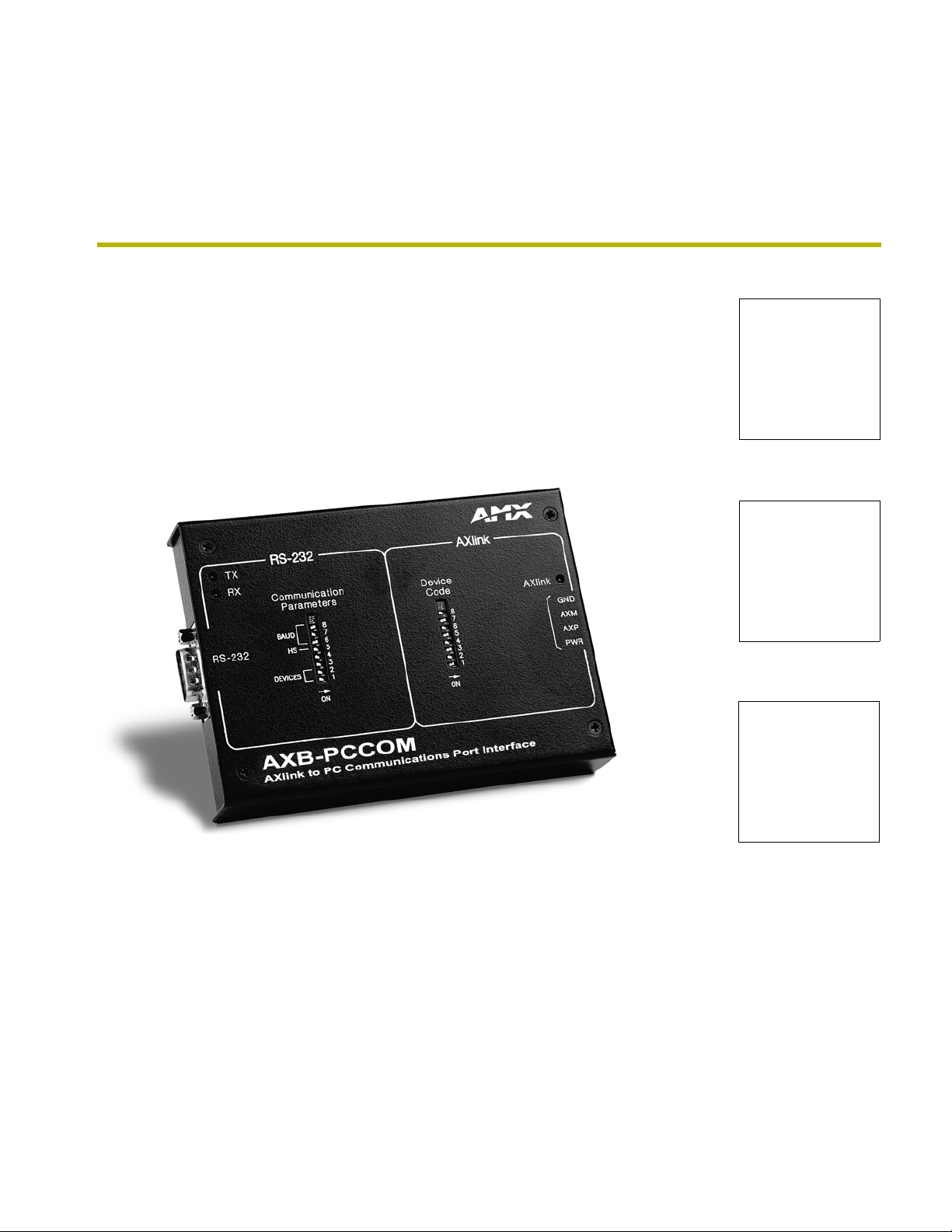
The AXB-PCCOM (FIG. 1) allows you to use a personal computer (PC) as a touch panel to control
Axcess systems.
TX LED
RX LED
TX
RS-232
connector
RX
RS-232
COMMUNICATION
BAUD
HS
DEVICES
PARAMETERS
Product Information
AXlink
LED
DEVICE
CODE
8
7
6
5
4
3
2
1
ON
8
7
6
5
4
3
2
1
ON
AXlink
GND
AXM
AXP
PWR
AXlink
connector
Communication
Para me te rs
DIP switch
Device Code
DIP switch
FIG. 1 AXB-PCCOM top view
The AXB-PCCOM:
Allows a PC (Macintosh, IBM-compatible, or other RS-232 device) to emulate up to four
AXlink bus devices.
Allows you to create custom PC software applications (conforming to the AXB-PCCOM
protocols) to control AXCESS systems.
Can be located up to 3,000 feet from AXCENT, AXCENT
2
, or Axcess card cage. This
overcomes the RS-232 distance limitation of 50 feet or less.
Does not require special Axcess programming to work on AXlink. In programming, treat
AXB-PCCOM as a standard Axcess panel.
AXB-PCCOM Communications Port Interface
1
Page 6

Product Information
Specifications
The following table details the specifications for the PCCOM.
Specifications
Dimensions (HWD) 1.00" x 5.26" x 3.75" (2.54 cm x 13.36 cm x 9.53 cm)
Enclosure Metal with black matte finish
Power Consumption 75 mA @ 12 VDC
Input buffer • 12,000 bytes
Output buffer (AXlink) • 12,000 bytes
Baud range • 300 - 38.4 K
Max. Length of
SEND_STRING to device
Max. Length of data packets
from device
Weight 8.60 oz. (243.80 g)
Panel Components
RS-232 connector A DB-9 RS-232 connector used for communication with the PC for AMX
TX LED (Red) Blinks to indicate that the AXB-PCCOM is transmitting data.
RX LED (Red) Blinks to indicate the AXB-PCCOM is receiving data. The RX LED blinks even
Communications Parameter
DIP switch
AXlink LED AXlink LED (green and blinks to indicate AXlink communication activity and
AXlink connector This four-pin captive wire receives power and information via the AXlink bus
Device DIP switch An eight-position DIP switch used to set the AXlink device number for the
•64
•64
programming tools, such as Axcess and IRLIB.
if the data is incorrect.
An eight position DIP switch used to set the number of AXlink devices
emulated, enable or disable handshaking, and set the Baud rate.
power:
• Full-Off indicates no power is being received or the controller is not
• functioning properly.
• One blink per second indicates power is active and AXlink communication is
• functioning.
• Full-On indicates there is no AXlink control or activity, but power is on.
and AXlink system controller.
AXB-PCCOM.
DIP Switches
Communication Parameters
The AXB-PCCOM has these default configurations settings:
Parity: None
Stop Bits: 1
Data Bits: 8
Use the Communication Parameters DIP switch to set the communications parameters. Switches 1
and 2 determine how many AXlink devices the PC device is emulating. Switch 5 enables the
hardware handshaking. Switches 6 through 8 determine the baud rate. Switches 3 and 4 are
reserved for future use. As an example, the DIP switch below (FIG. 2) defines four devices, a baud
rate of 9,600, with handshaking disabled.
2
AXB-PCCOM Communications Port Interface
Page 7

Product Information
1 2 3 4 5 6 7 8
FIG. 2 Communications Parameters DIP switch setting example
ON
The following table describes the Communications Parameters DIP switch settings and its
corresponding DIP switch arrangements.
Communications Parameters DIP switch settings
Switch 1 Switch 2 Switch 3 and 4 Switch 5 Switch 6 Switch 7 Switch 8
Off Off Off Off Off Off
Two AXlink devices (Reserved) Handshaking disabled 300 Baud
On Off On On Off Off
Two AXlink devices Handshaking disabled 600 Baud
Off On Off On Off
Three AXlink devices 1,200 Baud
On On On On Off
Four AXlink devices 2,400 Baud
Off Off On
4,800 Baud
On Off On
9,600 Baud
Off On On
19,200 Baud
On On On
38,400 Baud
Device Code
Use Device Code DIP switch to set the AXB-PCCOM AXlink device number. You can set it as one
of 255 devices in an Axcess, AXCENT, or AXCENT
2
system. Set the device number with the total
of all ON (down) switches. As an example, the DIP switch (FIG. 3) defines Device 128.
1 2 3 4 5 6 7 8
FIG. 3 Device Code DIP switch setting example
ON
The following table describes the Device Code DIP switch settings and its corresponding DIP
switch arrangements.
Device DIP switch settings
Position 12345678
Value 1248163264128
The device number takes effect only on power-up. If you later change the device
number, remove and reconnect the AXlink connector. This enters the new device
number into memory.
AXB-PCCOM Communications Port Interface
3
Page 8

Product Information
AMX standard device numbers are assigned as follows:
Cards are 1 through 25.
Boxes are 96 through 127.
Panels are 128 through 255.
The AXB-PCCOM emulates as a touch panel. Set the device number to one in the panel range.
Connectors
Preparing/connecting captive wires
You will need a wire stripper and flat-blade screwdriver to prepare and connect the captive wires.
Never pre-tin wires for compression-type connections.
1. Strip 0.25 inch of wire insulation off all wires.
2. Insert each wire into the appropriate opening on the connector according to the wiring
diagrams and connector types described in this section.
3. Do not tighten the screws excessively; doing so may strip the threads and damage the
connector
Using the AXlink connector for data and power
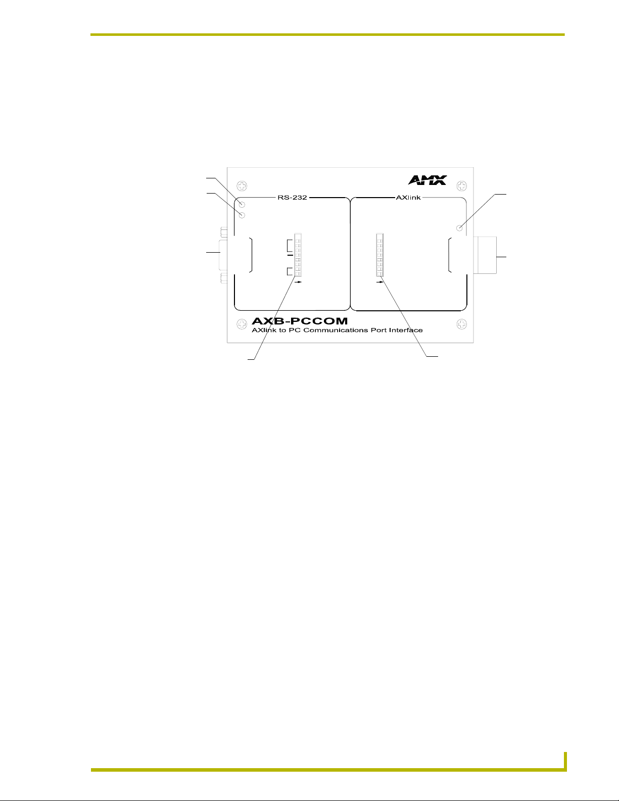
To use the AXlink 4-pin connector for data communication and for power supply, the incoming
PWR and GND cable from the control system must be connected to the AXlink cable connector
going to the control system. The AXlink connector is located on the side of the PCCOM (FIG. 4) is
a four-wire, captive compression connector.
Four-pin AXlink connector
FIG. 4 AXlink connector location on AXB-PCCOM
Install the AXlink data/power as sown in the AXlink wiring diagram (FIG. 5).
PWR +
AXP/TX
AXM/RX
GND -
PWR +
AXP/TX
AXM/RX
GND -
To the AXB-PCCOM
FIG. 5 AXlink connector wiring diagram
4
AXB-PCCOM Communications Port Interface
To the Control system
Page 9

Product Information
Using the RS-232 (DB-9) connector control or data
The AXB-PCCOM uses the dual-function (DB-9) RS-232 connector (FIG. 6) to communicate with
the PC.
RS-232 connector
FIG. 6 RS-232 (DB-9) connector location on AXB-PCCOM
The following table lists (DB-9) RS-232 connector pinouts and signal definitions.
(DB-9) RS-232 Connector Pinouts
Pin Signal Function
5
4
3
2
1
DB-9 (male)
9
8
7
6
Male
1 N/A Not used
2 RXD Receive data
3 TXD Transmit data
4 DTR Data terminal ready (not used)
5 GND Signal ground
6 N/A Not used
7 RTS Request to send (not used)
8 CTS Clear to send (not used)
9 N/A Not used
DB-9 (female)
9
8
7
6
Female - on PCCOM
AXB-PCCOM Communications Port Interface
5
Page 10

Product Information
6
AXB-PCCOM Communications Port Interface
Page 11

Programming
Requests
Enter the numeric value only; do not enter the brackets.
Examples shown are in the Axcess programming language syntax.
All values expressed in brackets are true decimal values.
Replace the comma delimiter, as used in the examples, with the delimiter accepted by
your PC or RS-232 device. (Refer to your PC or device user's or reference guide.)
The DEVICE value is not the AXlink device code. It is the value incremented from the
AXB-PCCOM DEVICE value, which should be 0. If you configure the AXB-PCCOM
for multiple devices, the successive device values will be 1, 2, and 3.
Valid values for <LEVEL NO> are 0 through 7, and correspond to Axcess levels 1
through 8. (For example, 0 corresponds to 1, 1 corresponds to 2, and so on.)
CHECKSUM the sum of all bytes mod 256.
For the equation X mod Y = N, X is divided by Y, with the remainder being N.
Programming
All examples are for an AXB-PCCOM set as AXlink device number 128, configured for
four devices
Request Commands
The following table lists the request commands sent to the AXB-PCCOM :
Requests sent to the AXB-PCCOM
Command Packet Structure and Example
DO Push/Release Syntax:
'*' <1> <DEVICE> <CHANNEL> <STATUS> <CHECKSUM>
"'*',1,0,1,1,45"
(Status Byte: 1 = Push; 0 = Release). Push channel 1 on device 0 (AXlink device
128).
Example:
"'*',1,3,255,0,45"
Release channel 255 on device 3 (AXlink device 131).
Get Bus Status Syntax:
'*' <8> <CHECKSUM>
Example:
"'*',8,50"
Request bus status. The AXB-PCCOM responds with a BUS STATUS string.
Get Channel Status Syntax:
'*' <6> <DEVICE> <CHANNEL> <CHECKSUM>
Example:
"'*',6,0,100,148"
Request the channel status for channel 100 on device 0 (AXlink device 128). The
AXB-PCCOM responds with a CHANNEL STATUS string.
AXB-PCCOM Communications Port Interface
7
Page 12

Programming
Requests sent to the AXB-PCCOM (Cont.)
Command Packet Structure and Example
Get Devices Syntax:
'*' <9> <CHECKSUM>
Example:
"'*',9,51"
Request the devices and device numbers of the AXB-PCCOM. The AXB-PCCOM
responds with a DEVICE LIST string.
Get Level Status Syntax:
'*' <7> <DEVICE> <LEVEL> <CHECKSUM>
Example:
"'*',7,2,7,58"
Request the level for level 7 on device 2 (AXlink device 130). The AXB-PCCOM
responds with a CHANGE LEVEL string.
Pulse Push/Release Syntax:
'*' <2> <DEVICE> <CHANNEL> <CHECKSUM>
Example:
"'*',2,0,1,45"
Push and release channel 1 on device 0 (AXlink device 128).
Send All Levels Syntax:
'*' <12> <DEVICE> <CHECKSUM>
Example:
"'*',12,2,56"
Request the AXB-PCCOM to send level status for all levels on device 2 (AXlink
device 129). The AXB-PCCOM responds with a CHANGE LEVEL string for each level
for device 2.
Send All On Channels Syntax:
'*' <11> <DEVICE> <CHECKSUM>
Example:
"'*',11,1,54"
Request the AXB-PCCOM to send all on channels for device 1 (AXlink device 129).
The AXB-PCCOM responds with a channel status string for each channel that is On
for device 1.
Send Command Syntax:
'*' <5> <DEVICE> <# BYTES> <STRING> <CHECKSUM>
Example:
"'*',5,3,9,'COMMAND 0',138"
Device 3 (AXlink device 131) sends the command 'COMMAND 0' to the master card
from device 3 (AXlink device 131).
Send String Syntax:
'*' <4> <DEVICE> <# BYTES> <STRING> <CHECKSUM>
Example:
"'*',4,0,9,'AXB-PCCOM',177"
Send the string 'AXB-PCCOM' to a buffer assigned to device 0 (AXlink device 128).
8
AXB-PCCOM Communications Port Interface
Page 13

Requests sent to the AXB-PCCOM (Cont.)
Command Packet Structure and Example
Set Level (Byte) Syntax:
'*' <3> <DEVICE> <LEVEL NO> <LEVEL> <CHECKSUM>
Example
"'*',3,1,0,200,246"
Set level 0 on device 1 (AXlink device 129) to 200.
Set Level (Word) Syntax:
'*' <13> <DEVICE> <LEVEL NO><LEV_H><LEV_L><CHECKSUM>
Example:
"'*',13,1,0,128,0,184"
Set level 0 on device 1 (AXlink device 129) to 32768.
Set Response Mask Syntax:
'*' <10> <MASK1> <MASK2> <CHECKSUM>
Examples:
"'*',10,32,0,212"
Set the AXB-PCCOM to send only CHANNEL STATUS strings.
"'*',10,160,0,84"
Set the AXB-PCCOM to send CHANNEL STATUS and RECEIVE STRING strings.
Refer to the Response Mask section on page 11 for more information.
Programming
Send_Commands
The following table lists the Send_Commands for the AXB-PCCOM :
AXB-PCCOM Send_Commands
Command Packet Structure and Example
’RXON
’RXOFF’
’LEVON’
’LEVOFF’
’PASS ON’
’PASS OFF’
’SS-’
Enables strings to be sent to master.
Disables strings to be sent to master.
Enables levels to be sent to master.
Disables levels to be sent to master.
AXB-PCCOM is put into PASS mode where any string sent from master will be sent
without protocol formatting, and any string received will be sent to master without
protocol checking. The PCCOM will act like a AXB-232 with the capability to send and
receive strings.
Turns off PASS mode. PCCOM operates normally.
Allows a RAW string to be sent from the PCCOM. Any characters after the '-' will be
sent without PCCOM protocol formatting.
AXB-PCCOM Communications Port Interface
9
Page 14

Programming
Response Commands
The following table lists the response commands sent to the AXB-PCCOM when set as device
number 128, configured for four devices :
Return/Requests sent to the AXB-PCCOM
Command Packet Structure and Example
Bus LED Status Syntax:
'&' <5> <STATUS> <CHECKSUM>
Examples:
"'&',5,1,44"
The bus LED is On.
"'&',5,0,43"
The bus LED is Off.
Bus Status Syntax:
'&' <6> <STATUS> <CHECKSUM>
Example
"'&',6,1,45"
The bus is on-line.When you reset AXlink, it sends BUS STATUS without being queried. When AXlink goes back on-line, it sends BUS STATUS again.
"'&',6,0,44"
The bus is Off-line.
Change Level Syntax:
'&' <2> <DEVICE> <LEVEL NO> <LEVEL> <CHECKSUM>
Example:
"'&',2,1,2,132,175"
Level 2 on device 1 (AXlink device 129) is 132.
Channel Status Syntax:
'&' <1> <DEVICE> <CHANNEL> <STATUS> <CHECKSUM>
Example:
"'&',1,0,255,1,39"
Channel 255 on device 0 (AXlink device 128) is On.
"'&',1,3,100,0,142"
Channel 100 on device 3 (AXlink device 131) is Off.
Device List Syntax:
'&' <7> <# DEVICES> <DEVICES> <CHECKSUM>
Example:
"'&',7,4,128,129,130,131,55"
The AXB-PCCOM is configured for four devices, and their device numbers are 128,
129, 130, and 131.
Receive Command Syntax:
'&' <4> <DEVICE> <# BYTES> <STRING> <CHECKSUM>
Example:
"'&',4,3,9,'COMMAND 0',133"
AXCESS sent the command 'COMMAND 0' to device 3 (AXlink device 131).
10
AXB-PCCOM Communications Port Interface
Page 15

Programming
Return/Requests sent to the AXB-PCCOM
Command Packet Structure and Example
Receive String Syntax:
'&' <3> <DEVICE> <# BYTES> <STRING> <CHECKSUM>
Example:
"'&',3,0,9,'AXB-PCCOM',172"
AXCESS sent the string 'AXB-PCCOM' to device 0 (AXlink device 128).
Response Mask
If the AXB-PCCOM receives a change, it sends data automatically. Disable this feature if the data
is not used. Bits in the response mask will turn off the data.
1 = ON Data sent
0 = OFF Data not sent.
Response Mask for the AXB-PCCOM
Byte Bit Data Controlled Default
First byte (mask 1) 7 (msb) Receive String 1
6 Receive Channel 1
5 Channel Change 1
4 Level Change 1
3 Bus LED 0
2 (Reserved for Future use) 0
1 (Reserved for Future use) 0
0 (lsb) (Reserved for Future use) 0
Second byte (mask 2) 7 (msb) (Reserved for Future use) 0
6 (Reserved for Future use) 0
5 (Reserved for Future use) 0
4 (Reserved for Future use) 0
3 (Reserved for Future use) 0
2 (Reserved for Future use) 0
1 (Reserved for Future use) 0
0 (lsb) (Reserved for Future use) 0
Axcess Master Mode
When an Axcess device is placed in "Master Mode", the Central Controller’s PROGRAM port is
moved to the Axcess device’s RS-232 port.
Press the escape key, then type either MC or MD:
<esc>MC - connects the device in Master Mode
<esc>MD - disconnects the device
where <esc> means "press the Esc key".
Master Mode can be very useful in situations where physical access to the Central
Controller’s
Central Controller is located a long distance from the bus device(s)).
AXB-PCCOM Communications Port Interface
PROGRAM port is not practical (for example, in installations where the
11
Page 16

AMX reserves the right to alter specifications without notice at any time.
ARGENTI NA • AUST RALIA • B ELGIUM • BRAZIL • CANADA • CHINA • E NGLAND • FRANCE • GERMAN Y • GREEC E • HONG K ONG • IN DIA • IND ONESIA • ITALY • JAPAN
LEBANON • MALAYSIA • MEXICO • NETHERLANDS • NEW ZEALAND • PHILIPPINES • PORTUGAL • RUSSIA • SINGAPORE • SPAIN • SWITZERLAND • THAILAND • TURKEY • USA
ATLANTA • BOSTON • CHICAGO • CL EVELAND • DALLAS • DENVER • INDIANAPOLIS • LOS ANGELES • MINNEAPOLIS • PHILADELPHIA • PHOENIX • PORTLAND • SPOKANE • TAMPA
3000 RESEARCH DRIVE, RICHARDSON, TX 75082 USA • 800.222.0193 • 469.624.8000 • 469-624-7153 fax • 800.932.6993 technical support • www.amx.com
2005 AMX Corporation. All rights reserved. AMX, the AMX logo, the building icon, th e home icon, and the light bulb icon are all trademarks of AMX Corporation.
©
032-004-1020 9/05
In Canada doing business as Panja Inc.
Last Revision: 9/12/05
 Loading...