


AXB-232++
RS-232/422/485 Interface
instruction manual
AXlink Bus Controllers


Table of Contents
Table of Contents
Product Information .................................................................................................1
Front Panel........................................................................................................................ 1
Rear Panel ........................................................................................................................ 1
Specifications .................................................................................................................... 2
Installation and Wiring .............................................................................................3
Setting the Internal Jumpers ............................................................................................. 3
Setting jumper JP4 to terminate RS-422 input with 100 ohms................................................. 3
Setting jumper JP5 to set the RS-422 port for RS-485 use ..................................................... 4
Setting the DIP Switches................................................................................................... 4
Setting the DEVICE DIP switch................................................................................................ 4
Setting the RS-232/422 DIP switch.......................................................................................... 5
Wiring Devices to the AXB-232++..................................................................................... 6
Preparing captive wires ............................................................................................................ 6
Wiring guidelines...................................................................................................................... 6
Using AXlink............................................................................................................................. 6
Using AXlink and External Power Supply ................................................................................ 6
Using RS-232........................................................................................................................... 7
Using Hardware Handshaking ................................................................................................. 7
Using RS-422........................................................................................................................... 7
Using RS-485........................................................................................................................... 7
Rack-mounting the AXB-232++ (optional) ............................................................................... 8
Replacing the Lithium Batteries ............................................................................................... 8
Programming ............................................................................................................9
Send_Commands.............................................................................................................. 9
Axcess program characteristics ............................................................................................. 11
Send_String Escape Sequences..................................................................................... 12
AXB-232++ Program Statements.................................................................................... 13
Xmodem Timing Commands........................................................................................... 14
AXlink Master Statements ............................................................................................... 14
Reserved Channels......................................................................................................... 15
Axcess Master Mode....................................................................................................... 15
AXB-232++ RS-232/422/485 Interface
i

Table of Contents
ii
AXB-232++ RS-232/422/485 Interface
Product Information
The AXB-232++ RS-232/422/485 Interface is an AXlink bus controller that provides remote
control for devices that require a variety of control protocols. The AXB-232++ extends RS-232,
RS-422, or RS-485 control to remote sources over the 4-wire AXlink data/power bus.
Onboard processing and memory allows the controller to take on complex tasks by itself, reducing
the processing burden for the Axcess control system. For example, the control system can use
simplified commands for generic video switcher or code control, a modular driver program in the
AXB-232++ can process control for specific makes and models.
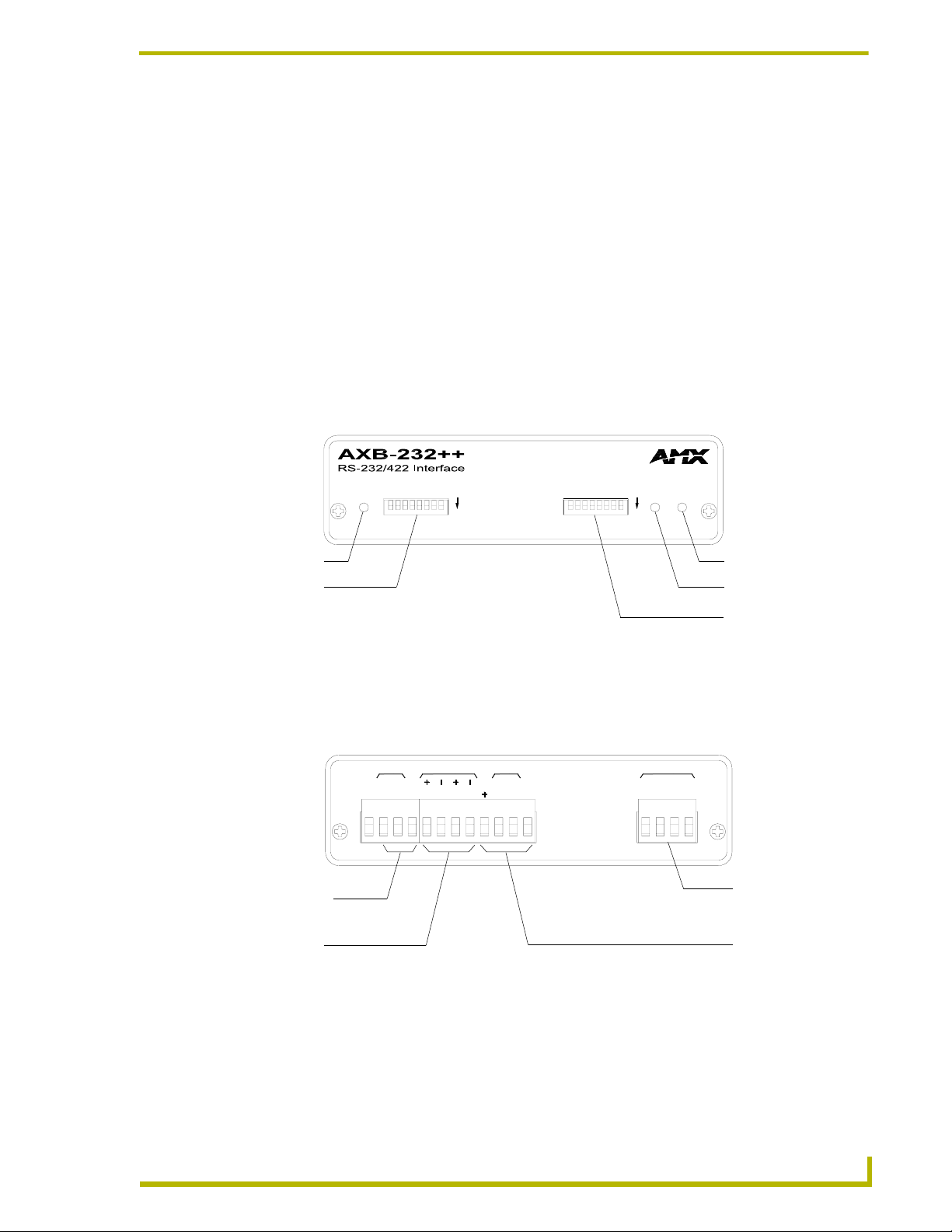
Front Panel
FIG. 1 displays the front panel of the AXB-232++.
Product Information
AXlink
DEVICE
ON
AXlink LED
DEVICE DIP
switch
FIG. 1 AXB-232++ front panel
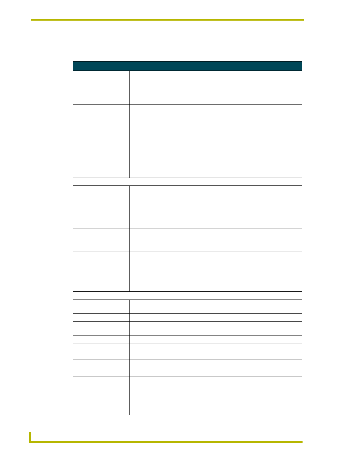
Rear Panel
FIG. 2 displays the rear panel of the AXB-232++.
RS232
RTS
Hardware
handshaking
connections
RS422
connections
FIG. 2 AXB-232++ rear panel
RS422
CTS
TX
GND
TX
RS232
12V
GND
TX
RX
RX
RX
RS-232/422
TXRX
ON
TX LED
RX LED
RS-232/422
DIP Switch
AXlink
AXM
AXP
GND
PWR
AXlink connector
RS232
connections
AXB-232++ RS-232/422/485 Interface
1
Product Information
Specifications
The following table lists the specifications for the AXB-232++.
Specifications
Power 12 VDC @ 160 mA
Processor On board 32-bit processor and 384K (of non-volatile memory) run Axcess
programs independent of the control system. This relieves the AXlink bus and
controller for the processing time for controlling those devices. (Requires Axcess
Version 3.0 or higher.)
Asynchronous data
standards
Buffers • 1KB input buffer
Front Panel
AXlink LEDs Green AXlink status indicator:
RX LED (Red) Blinks to indicate the AXB-232++ is receiving RS-232, RS-422, or RS-485 data.
TX LED (Red) Blinks to indicate the AXB-232++ is sending RS-232, RS-422, or RS-485 data.
DEVICE DIP Switch An eight-position DIP switch used to set the device number for the AXB-232++.
RS232/422 DIP Switch An eight-position DIP switch used to set the communication parameters for the
Rear Panel
Hardware handshaking
connector
RS422/232 connector A captive-wire connector wired for RS-422/232 data control (8-pin male).
AXlink connector Receives power and data via the AXlink bus and AXlink system controller
Internal Jumpers Sets differential input termination and enables RS-485 output.
Supports XON/XOFF software and hardware handshaking
Dimensions (HWD) 1.5" x 5.5" x 5.5" (3.81 cm x 13.97 cm x 13.97 cm)
Weight 1.1 lbs. (498.95 g)
Enclosure Metal with black matte finish
Included Accessories • AXlink connector (4-pin female)
Optional Accessories • CC-232 Control Cable
• Baud rates - 300, 600, 1200. 2400, 4800, 9600, 19200 and 38400.
56400 is supported via the BAUDMED Send Command (see the
Send_Commands section on page 9 for details).
115200 is supported via the BAUDHIGH Send Command (see the
Send_Commands section on page 9 for details).
• Data bits - 7, 8, and 9
• Stop bits - 1 and 2
•Parity - None, Odd, Even, Mark and Space
• 1KB AXlink buffer
• Full-Off indicates no power is being received or the controller is not functioning
properly.
• One blink per second power is active and AXlink communication is functioning.
• Full-On indicates power is active and AXlink data communication is not
functional.
The RX LED blinks even if the data being received is incorrect.
Refer to Setting the DEVICE DIP switch, on page 4, and Setting jumper JP5 to set
the RS-422 port for RS-485 use section on page 4 for more information.
RS-232/422 device. Refer to Setting the RS-232/422 DIP switch, on page 5, for
more information.
An RTS/CTS data connector that can be wired for hardware handshaking if called
for by the controlled device (4-pin male).
(4-pin male).
• Phoenix connector (8-pin male)
• AC-RK Accessory Rack Kit
• 12 VDC power supply, 800 mA
2
AXB-232++ RS-232/422/485 Interface

Installation and Wiring
A
The AXB-232++ can be used as an independent RS-232/422/485-controlled interface by setting the
internal jumpers. Configure the communication parameters using the DIP switches on the front
panel.
Setting the Internal Jumpers
Installation and Wiring
JP4
JP5
1998
CORP.
XB-232++
FIG. 3 Location of internal jumpers
front
Internal jumper JP4
Internal jumper JP5
Setting jumper JP4 to terminate RS-422 input with 100 ohms
Terminating a device involves installing a 100 ohm line terminator, this is typically used to achieve
better communication and signal integrity. You will want to terminate when the communication is
at a high data rate or over a long distance. Termination can be harmful because it increases the
current in the line, and more radiation that could interfere with signals.
Jumper JP4 places 100 Ohms termination across RS422 receive data pins 5 & 6:
1. Disconnect the RS-232/422/485 connectors.
2. Unscrew the two screws on the rear panel, and remove the panel.
3. Slide the circuit board out of the enclosure.
4. Locate the JP4 jumper (FIG. 3).
5. Install the jumper in the 'ON' position (default setting = OFF).
6. Slide the circuit board back into the enclosure.
7. Replace the panel, and refasten the screws.
8. Reconnect the RS-232/422/485 connectors.
AXB-232++ RS-232/422/485 Interface
3

Installation and Wiring
Setting jumper JP5 to set the RS-422 port for RS-485 use
1. Disconnect the RS-232/422/485 connectors.
2. Unscrew the two screws on the rear panel, and remove the panel.
3. Slide the circuit board out of the enclosure.
4. Locate the JP5 jumper (see FIG. 3 on page 3).
5. Set jumper JP5 to the ON position (the default setting is OFF).
6. Slide the circuit board back into the enclosure.
7. Replace the panel, and refasten the screws.
8. Reconnect the RS-232/422/485 connectors.
Setting the DIP Switches
Use the DIPSwitch 2.0 application available for free download from AMX to quickly
figure out DIP Switch settings for all types of DIP Switches.
Setting the DEVICE DIP switch
Set the device number on
DEVICE DIP switch, located on the front of the AXB-232++. The device
can be 1 of the 255 devices in an Axcess control system. The device number must match the device
assignment in the Axcess program. Device numbers are assigned into the following three segments:
Cards 1 through 95
Boxes 96 through 127
Panels 128 through 255
Set the device number by setting the device DIP switches. The device number is the total of all of
the switches in the ON position, and take effect by cycling the power. The following table shows
the switch numbers and their corresponding values.
DEVICE DIP Switch Settings
Position 12345678
Value 1 2 4 8 16 32 64 128
4
AXB-232++ RS-232/422/485 Interface

Installation and Wiring
Setting the RS-232/422 DIP switch
Set the stop bits, data bits, parity, and baud rate on the RS-232/422 DIP switch, located on the front
panel (see FIG. 1 on page 1). The AXB-232++ supports the following asynchronous data
standards:
Stop bits 1 and 2
Data bits 7, 8, and 9
Parity None, Odd, Even, Mark, and Space
Baud rates 300, 600, 1,200, 2,400, 4,800, 9,600, 19,200 and 38,400.
57,600 is achieved by setting the DIP switch to 300 baud, and using the
’
BAUDMED’ Send_Command (see the Send_Commands section on page 9 for
details).
115,200 is achieved by setting the DIP switch to 300 baud, and using the
’
BAUDHIGH’ Send_Command (see the Send_Commands section on page 9 for
details).
The table below shows the RS-232/422 DIP switch numbers, functions, and their corresponding
values.
RS-232/422 DIP Switch Settings
Switch1 2 3456 7 8
Function Stop Bits Data Bits Parity Baud Rates
Setting Off Off Off Off Off Off Off Off
Value 2 bits 7 bits Unused 300
On On On Off Off On Off Off
1 bit 8 bits Unused 600
Off On Off Off On Off
Unused 1,200
RS232/422
12345 678
ON
On On Off On On Off
Unused 2,400
Off Off On Off Off On
Mark 4,800
On Off On On Off On
Even 9,600
Off On On Off On On
Odd 19,200
On On On On On On
None 38,400
AXB-232++ RS-232/422/485 Interface
5

Installation and Wiring
Wiring Devices to the AXB-232++
Preparing captive wires
To connect the wiring into a captive-wire connector:
1. Strip 1/4 inch off the wire insulation for all four wires.
2. Tin 2/3 of the exposed wire.
3. Insert each wire into the appropriate captive-wire connector up to the insulation.
4. Tighten the captive screws to secure the fit in the connector.
If the device is using a separate power supply, do not connect the power wiring from
the AXB-232++ to that device.
Wiring guidelines
The interface requires a 12 VDC power to operate properly. The interface uses a PSN2.8 power
supply. The Central Controller supplies power via the AXlink cable or external 12 VDC power
supply. The maximum wiring distance between the Central Controller and interface is determined
by power consumption, supplied voltage, and the wire gauge used for the cable. The table below
lists wire sizes and maximum lengths allowable between the AXB-RS232++ and Central
Controller. The maximum wiring lengths for using AXlink power are based on a minimum of 13.5
volts available at the Central Controller’s power supply.
Wiring Guidelines at 160 mA
Wire Size Maximum Wiring Length
18 AWG 733.57 feet (223.59 m)
20 AWG 464.11 feet (141.46 m)
22 AWG 289.35 feet (88.19 m)
24 AWG 182.39 feet (55.59 m)
Using AXlink
Connect the AXlink wiring to the connector on the AXB-232++ as shown in FIG. 4.
PWR
AXlink
FIG. 4 AXlink bus and +12 VDC power wiring
AXP
AXM
GND
PWR
AXP
AXM
GND
System
Using AXlink and External Power Supply
Connect the AXlink and power wiring to the connector on the AXB-232++ as shown in FIG. 5.
AXlink
PWR
AXP
AXM
GND
PWR
AXP
AXM
GND
System
+12 VDC
GND
FIG. 5 AXlink bus and +12 VDC power wiring
6
Powe r S up ply
AXB-232++ RS-232/422/485 Interface

Using RS-232
When communicating via RS-232, connect the wiring as shown in FIG. 6.
Installation and Wiring
AXB232++
FIG. 6 RS-232 wiring
GND
RX
TX
+12V
RX RX +
TX -
TX +
GND
RX
TX
Device
Using Hardware Handshaking
When the controlled device requires hardware handshaking, connect the wiring as shown in FIG. 7.
1
CTS
AXB-232++
FIG. 7 Hardware handshaking wiring
2
3
RTS
4
RTS
CTS
Device
Using RS-422
When communicating via RS-422, connect the wiring as shown in FIG. 8.
GND
RX
AXB232++
TX
+12V
RX RX +
TX -
TX +
GND
TX-
TX+
RX-
RX+
Device
FIG. 8 RS-422 wiring
Using RS-485
When communicating via RS-485, connect the wiring as shown in FIG. 9.
GND
RX
TX
+12V
RX -
AXB232++
FIG. 9 RS-485 wiring
AXB-232++ RS-232/422/485 Interface
RX +
TX -
TX +
Device
7

Installation and Wiring
Rack-mounting the AXB-232++ (optional)
To rack-mount the AXB-232++ into the optional AC-RK Accessory Rack Kit:
1. Remove any connected power, and AXlink and RS-232 connectors from the rear panel.
2. Remove the two screws on the front panel of the AXB-232++.
3. Remove the front panel and space bracket behind the panel.
4. Place the unit in the appropriate opening in the AC-RK.
5. Place the front panel of the AXB-232++ on the front of the rack, over the unit.
6. Fasten the front panel to the rack and unit with the two screws you removed.
Replacing the Lithium Batteries
The AXB-232++’s lithium batteries have a life of approximately 5 years to protect its memory.
When DC power is on, the batteries are not used. When you install the AXB-232++, record the date
the batteries should be replaced.
There is a danger of explosion if you replace the batteries incorrectly. Replace
batteries with the same or equivalent type recommended by the manufacturer.
Dispose of the used batteries according to the manufacturer’s instructions. Never
recharge, disassemble, or heat batteries above 212°F (100°C). Never solder directly
to the batteries or expose the contents of the batteries to water.
Before removing the lithium batteries, contact your dealer and verify that they have a current copy
of your program to avoid an inadvertent loss of data and prevent an unnecessary service outage.
1. Discharge the static electricity from your body.
2. Unplug the two-pin power connector and any other connectors.
3. Remove the two screws on the front panel.
4. Remove the front panel, and slide the circuit board out of the enclosure.
5. Carefully slide each battery out of its socket (FIG. 10), and insert the new battery.
Battery (CR2032 type - 20mm coin cell)
socket
FIG. 10 Lithium battery and socket
6. Slide the circuit board back into the enclosure.
7. Replace the front panel and refasten the two screws.
8. Reconnect any connectors that you removed.
8
AXB-232++ RS-232/422/485 Interface

Programming
Send_Commands
The AXB-232++ supports the same command set as the AXC-232. The following table lists the
AXB-232++ Send_Commands.
AXB-232++ Send_Commands
B9MOFF
Sets data bit mode to normal
with DIP switch settings
(default).
B9MON
Enables a special mode to
override DIP switch settings.
BAUDHIGH
Enables 115,200 baud rate
when the DIP switch is set to
300 baud.
BAUDLOW
Enables 300 baud rate when
the DIP switch is set to 300
baud setting (default).
BAUDMED
Enables 57,600 baud rate
when the DIP switch is set to
300 baud.
CB1ON
Enables placement of characters in the buffer specified by
CREATE_BUFFER 1
(default).
CB1OFF
Disables placement of characters in the buffer specified
by CREATE_BUFFER 1.
Programming
Syntax:
'B9MOFF'
Example:
SEND_COMMAND AXB232,'B9MOFF'
Sets the data bit mode to normal.
Syntax:
'B9MON'
The mode, nine data bits with one stop bit, overrides the data, stop, and parity
settings. When the AXB-232++ issues this command, it locks in the baud rate
determined by the current DIP switch setting.
Example:
SEND_COMMAND AXB232,'B9MON'
Overrides the DIP switch settings.
Syntax:
'BAUDHIGH'
Example:
SEND_COMMAND AXB232,'BAUDHIGH'
Enables 115,200 baud rate.
Syntax:
'BAUDLOW'
Example:
SEND_COMMAND AXB232,'BAUDLOW'
Enables 300 baud rate.
Syntax:
'BAUDMED'
Example:
SEND_COMMAND AXB232,'BAUDMED'
Enables 57,600 baud rate.
Syntax:
'CB1ON'
Example:
SEND_COMMAND AXB232,'CB1ON'
Enables placement of characters in the buffer.
Syntax:
'CB1OFF'
Example:
SEND_COMMAND AXB232,'CB1OFF'
Disables placement of characters in the buffer.
AXB-232++ RS-232/422/485 Interface
9

Programming
AXB-232++ Send_Commands (Cont.)
CHARD
Sets delay between all
transmitted characters to the
increment specified.
CTSPSH
Enables PUSHes and
RELEASEs.
CTSPSHF
Disables the 'CTSPSH'
command.
EOFF
Disables the 'EON '
command (default).
EON
Forces the AXB-232++ to
ignore the transmitted characters on its receiver.
HSOFF
Disables hardware
handshaking (default).
HSON
Disables placement of characters in the buffer specified
by CREATE_BUFFER 1.
RXCLR
Clears any characters in the
Receive buffer waiting to be
sent to the Master.
Syntax:
'CHARD-<time>'
Var iabl e:
time = 100 microsecond increments 0 - 255.
Example:
SEND_COMMAND AXB232,'CHARD-10'
Sets 1mS delay between all transmitted characters.
Syntax:
'CTSPSH'
Example:
SEND_COMMAND AXB232,'CTSPSH'
Enables PUSHes, RELEASEs, and status on channel 255 ([0,255] within the
AXB-232++) for CTS hardware handshake input. If CTS is high, the channel is
on.
Syntax:
'CTSPSHF'
Example:
SEND_COMMAND AXB232,'CTSPSHF'
Disables the 'CTSPSH' command.
Syntax:
'EOFF'
Example:
SEND_COMMAND AXB232,'EOFF'
Disables the 'EON' command.
Syntax:
'EON'
Example:
SEND_COMMAND AXB232,'EON'
Forces the AXB-232++ to ignore the transmitted characters on its receiver.
When using RS-485, the transmitter and receiver are tied together.
Syntax:
'HSOFF'
Example:
SEND_COMMAND AXB232,'HSOFF'
Enables placement of characters in the buffer.
Syntax:
'HSON'
Example:
SEND_COMMAND AXB232,'HSON'
Enables hardware handshaking.
Syntax:
'RXCLR'
Example:
SEND_COMMAND AXB232,'RXCLR'
Clears any characters in the Receive buffer waiting to be sent to the master. If
'RXCLR' is sent while RTS is low, RTS returns high.
10
AXB-232++ RS-232/422/485 Interface

AXB-232++ Send_Commands (Cont.)
RXOFF
AXB-232++ does not pass on
received characters to the
Master (default).
RXON
Enables AXB-232++ to send
incoming characters received
to the Master.
TXCLR
Clears and stops any characters waiting in the Transmit
buffer.
XOFF
Disables software
handshaking (default).
XON
Enables software
handshaking.
ZAP!
Clears the Axcess program in
the AXB-232++.
Syntax:
'RXOFF'
Example:
SEND_COMMAND AXB232,'RXOFF'
AXB-232++ does not pass on received characters to the master.
Syntax:
'RXON'
Example:
SEND_COMMAND AXB232,'RXON'
Enables AXB-232++ to send incoming characters received to the master.
The AXB-EM automatically sends this command to the AXB-232++ when it
executes a 'CREATE_BUFFER' program instruction.
Syntax:
'TXCLR'
Example:
SEND_COMMAND AXB232,'TXCLR'
Clears and stops any characters waiting in the Transmit buffer.
Syntax:
'XOFF'
Example:
SEND_COMMAND AXB232,'XOFF'
Disables software handshaking.
Syntax:
'XON'
Example:
SEND_COMMAND AXB232,'XON'
Enables software handshaking.
Syntax:
'ZAP!'
Example:
SEND_COMMAND AXB232,'ZAP!'
Clears the Axcess program in the AXB-232++.
Programming
Axcess program characteristics
The AXB-232++ is capable of running Axcess programs. It handles string processing, relieving
AXlink and the Master of the processing times.
AXB-232++ RS-232/422/485 Interface
11

Programming
Send_String Escape Sequences
The AXB-232++ does not regard certain three-character combinations within a Send_String
program as literal characters, but as commands. The following table lists those combinations.
Send_String Escape Sequences
27,17,<time>
Sends a break character of
the specified length of time.
27,18,1
Sets the ninth data bit to 1 for
all of the following characters
to be transmitted.
27,18,0
Clears the ninth data bit to 0
for all of the next characters
to be transmitted.
27,19,<time>
Inserts a delay before the
next character to be
transmitted.
27,20,0
Asserts RTS hardware handshake output high.
27,20,1
Asserts RTS hardware handshake output low.
Syntax:
"27,17,<time>"
Var iabl e:
time = 100 microsecond increments 1 - 255.
Example:
SEND_STRING AXB232,"27,17,10"
Sends a break character of 1mS.
Syntax:
"27,18,1"
Example:
SEND_STRING AXB232,"27,18,1"
Sets the ninth data bit to 1 for all of the following characters to be transmitted.
Used in conjunction with the 'B9MON' command.
Syntax:
"27,18,0"
Example:
SEND_STRING AXB232,"27,18,0"
Clears the ninth data bit to 0 for all of the next characters to be transmitted.
Used in conjunction with the 'B9MON' command.
Syntax:
"27,19,<time>"
Var iabl e:
time = 100 microsecond increments 1 - 255.
Example:
SEND_COMMAND AXB232,"27,19,10"
Inserts a 1mS delay before the next character to be transmitted.
Syntax:
"27,20,0"
Example:
SEND_COMMAND AXB232,"27,20,0"
Asserts RTS hardware handshake output high.
Syntax:
"27,20,1"
Example:
SEND_COMMAND AXB232,"27,20,1"
Asserts RTS hardware handshake output low.
12
AXB-232++ RS-232/422/485 Interface

Programming
AXB-232++ Program Statements
The Axcess program of the AXB-232++ communicates with the master as Device 0. Its device
communicates with the RS232/422 Input/Output (I/O) of the AXB-232++ as Device 1. The
following table lists AXB-232++ statements.
AXB-232++ Program Statements
Statement Function
CREATE_BUFFER
0,buffer
CREATE_BUFFER
1,buffer
CREATE_BUFFER
2,buffer
CREATE_LEVEL
0,level,variable
OFF[0,channel]
OFF[1,channel]
ON[0,channel]
ON[1,channel]
SEND_COMMAND
0,command
SEND_COMMAND
1,command
SEND_COMMAND
AXB_232,
'BAUDHIGH'
SEND_COMMAND
AXB_232, 'BAUDLOW'
SEND_COMMAND
AXB_232, 'CB1ON'
SEND_COMMAND
AXB_232, 'CB1OFF'
SEND_LEVEL
0,level,variable
SEND_STRING
0,string
SEND_STRING
1,string
Places strings that come from the Master into buffer. If no CREATE_BUFFER
0
exists, the incoming strings from the Master are sent out the RS232 port.
Places strings that come from the RS-232 port into buffer. If no
CREATE_BUFFER 1, exists, the incoming strings are sent to the Master.
Places commands (i.e. SEND_COMMANDs) that come from the AXlink Master
into the buffer. Each command will be preceded by 2 characters: The first character will always be an '*', the second character is the length of the command,
the remaining n characters (as given in the second character) are the
command itself.
Places levels sent by the master for level in variable.
• Sends a RELEASE to the Master.
• Sends a message that channel is off.
Turns off a channel. This command has no external effect. It can be used as
status.
• Sends a PUSH to the Master.
• Sends a message that channel is on.
Turns on channel. This command has no external effect. It can be used as status.
Sends command to the Master. Provides support for commands like 'RDS'.
Sends command to the AXB-232++ as if the Master had sent it.
Sets the baud rate to 115.2k (DIP switch set to 300).
Sets the baud rate to 300 (DIP switch set to 300).
Enables placement of characters in the buffer specified by
CREATE_BUFFER 1.
Disables placement of characters in the buffer specified by
CREATE_BUFFER 1.
Sends variable as the value for level.
Sends string to the Master.
Sends string out the RS-232 port.
AXB-232++ RS-232/422/485 Interface
13

Programming
Xmodem Timing Commands
The following table lists the AXB-232++ Xmodem timing commands. Xmodem timeouts exist to
accommodate potential Ethernet delays and for consistency among and within products. Any
Xmodem timing command will change timing and retries for Axcess code download as well as
Softrom transfer.
Xmodem Timing Commands
Command Description
'TIMEOUT XX'
SEND_COMMAND
SERIAL, 'XMTO XX'
'RETRY XX'
SEND_COMMAND
SERIAL, 'XMRT XX'
Xmodem timeouts via the Program Port. (Default is 10 sec.)
Over AXlink, where XX is from one to 50 seconds in 1-second increments.
Xmodem retries via the Program Port. (Default is 5.)
Over AXlink where XX is from one to 10 in increments of one.
AXlink Master Statements
The following table lists the AXlink Master statements for the AXB-232++.
AXlink Master Statements
Statement Function
MIN_TO
ON[AXB_232,
channel]
OFF[AXB_232,
channel]
PULSE
SEND_COMMAND
AXB_232,command
SEND_LEVEL
AXB_232,level,
variable
SEND_STRING
AXB_232,string
TO
Activates a channel or variable for a minimum amount of time-even if the corresponding device-channel is released. The time duration is determined by
SET_PULSE_TIME.
Executes PUSH[0,channel] within AXB-232++.
Executes RELEASE[0,channel] within AXB-232++.
Turns on a channel or variable for a certain amount of time. Once the time
elapses, the channel or variable is turned off. The Pulse time remains the same
value until it is changed within the program.
Example:
SET_PULSE_TIME(12)
Sets the current duration of future Pulses to 1.2 seconds.
AXB-232++ interprets command.
Places the variable into the CREATE_LEVEL variable, if it were defined in the
AXB-232++ DEFINE_START section.
Places the string into the CREATE_BUFFER buffer, if you defined the buffer in
the AXB-232++ DEFINE_START section. If it were not, this command transmits the string out the RS-232 port.
Activates a channel or variable for as long as the corresponding
device-channel of its Push statement is activated. When the device-channel
referenced by the Push statement changes from off to on, the TO starts activating the device-channel or variable in the brackets following it. When the
device-channel of its Push is released, the TO statement stops activating its
device-channel or variable. For this reason, TO must be found only underneath
a Push statement.
14
AXB-232++ RS-232/422/485 Interface

Programming
Reserved Channels
The following table lists the channels reserved on Device 0.
Reserved Channels
Channel Function
Channel 254 This is only valid within the device and is not sent to the AXlink Master. Reflects AXlink
Channel 255 Reflects the state of the CTS input. If the AXB-232++ receives a 'CTSPSH' command,
status:
• When AXlink is active, this channel is on.
• When AXlink is inactive, this channel is off.
• When this channel changes state, the AXB-232++ generates a PUSH or RELEASE.
it generates PUSHes for both the Master and the AXB-232++.
Axcess Master Mode
When an Axcess device is placed in "Master Mode", the Central Controller’s PROGRAM port is
moved to the Axcess device’s RS-232 port.
Press the escape key, then type either MC or MD:
<esc>MC - connects the device in Master Mode
<esc>MD - disconnects the device
where <esc> means "press the Esc key".
Master Mode can be very useful in situations where physical access to the Central
Controller’s PROGRAM port is not practical (for example, in installations where the
Central Controller is located a long distance from the bus device(s)).
AXB-232++ RS-232/422/485 Interface
15

AMX reserves the right to alter specifications without notice at any time.
ARGENTI NA • AUSTR ALIA • BEL GIUM • BRA ZIL • CANA DA • CHINA • ENGLAND • FRANCE • G ERMANY • GREECE • H ONG KONG • INDIA • IN DONESIA • ITALY • JAPAN
LEBANON • MALAYSIA • MEXICO • NETHERLANDS • NEW ZEALAND • PHILIPPINES • PORTUGAL • RUSSIA • SINGAPORE • SPAIN • SWITZERLAND • THAILAND • TURKEY • USA
ATLANTA • BOSTON • CHICAGO • CLEVELAND • DALLAS • DENVER • INDIANAPOLIS • LOS ANGELES • MINNEAPOLIS • PHILADEL PHIA • PHOENIX • PORTLAND • SPOKANE • TAMPA
3000 RESEARCH DRIVE, RICHARDSON, TX 75082 USA • 800.222.0193 • 469.624.8000 • 469-624-7153 fax • 800.932.6993 technical support • www.amx.com
2005 AMX Corporation. All rights reserved. AMX, the AMX logo, the building icon, th e home icon, and the light bulb icon are all trademarks of AMX Corporation.
©
032-004-1718 9/05
In Canada doing business as Panja Inc.
Last Revision: 09/12/05
 Loading...