

AMX AVS-OP-1616-110, AVS-OP-2404-110, AVS-OP-1624-110, AVS-OP-2416-110, AVS-OP-3604-110 Configuration Manual
...Page 1
Optim a matrix Switcher
cOnfig ur atiOn gui de
Page 2
Optima COnfiguratiOn guide
USB
50-60Hz 120-240VAC
100 Watts Max.
10/100
STATUS
PORT
COMM
+ - - +
RL
-
IN
L
+- +- -+
RLR
1 2
+ - - +
RL
5
+ - - +RL+ - - +
RL
3 4
+ - - +RL+ - - +
RL
6 7
+ - - +
RL
+ - - +
RL
OUT
L
- +
R
8 1 2
+ - - +RL+ - - +
RL
3 4
+ - - +RL+ - - +
RL
5 6 7
+ - - +
RL
8
IN
1 2 3 4 5 6 7
OUT
18 2 3 4 65 7 8
IN
21 3 4
OUT
1 2 3 4
IN
1 32 4 5 6 7 8
OUT
1 2 3 4 5 6 7 8
100 Watts Max.
50-60Hz 120-240VAC
10/100
USB
PORTLINK A
STATUS
COMM
OUTIN
13 14
1 2 5
1715 16
3 4
18 19
6 7
20 21 22
8 9 10
23 24
11 12
109 11
1 2 3
12 13
4 5
1514 16
76 8
OUTIN
13 14
1 2 5
1715 16
3 4
18 19
6 7
20 21 22
8 9 10
23 24
11 12
109 11
1 2 3
12 13
4 5
1514 16
76 8
OUTIN
13 14
1 2 5
1715 16
3 4
18 19
6 7
20 21 22
8 9 10
23 24
11 12
109 11
1 2 3
12 13
4 5
1514 16
76 8
100 Watts Max.
50-60Hz 120-240VAC
10/100
USB
PORTLINK A
STATUS
COMM
OUTIN
13 14
1 2 5
1715 16
3 4
18 19
6 7
20 21 22
8 9 10
23 24
11 12
109 11
1 2 3
12 13
4 5
1514 16
76 8
OUTIN
13 14
1 2 5
1715 16
3 4
18 19
6 7
20 21 22
8 9 10
23 24
11 12
109 11
1 2 3
12 13
4 5
1514 16
76 8
+ - - +
RL
OUT
+ - - +RL+ - - +
RL
13IN14
1 2
+ - - +RL+ - - +RL+ - - +
RL
+ - - +
RL
+ - - +RL+ - - +RL+ - - +
RL
+ - - +RL+ - - +
RL
+ - - +
RL
1715 16 18 19 20 21 22 23 24
3 4 5 6 7 8 9 10 11 12
+ - - +RL+ - - +
RL
+ - - +RL+ - - +RL+ - - +
RL
+ - - +
RL
+ - - +
RL
109 11 12 13 1514 16
21 3 4 5 6 7 8
+ - - +
RL
+ - - +RL+ - - +
RL
19IN20
1 2
+ - - +
RL
+ - - +
RL
23
+ - - +RL+ - - +
RL
21 22
3 4
+ - - +RL+ - - +
RL
24 25
5 6 7
+ - - +RL+ - - +
RL
26 27 28
8 9 10
+ - - +RL+ - - +
RL
29 30
11 12
+ - - +
RL
+ - - +RL+ - - +
RL
3231 33
1413 15
+ - - +RL+ - - +
RL
34 35
16 17
+ - - +RL+ - - +
RL
36 3
OUT
4
18 1 2
IN
1 2 3 4 5 6 7
OUT
18 2 3 4 65 7 8
11
1
IN
1611 12 13
1 2 3
14 15
4 5
17 18
6 7 8
19 20
OUT
9 10
1612 13
2 3
14 15
4 5 6
17 18
7 8
19 20
9 10
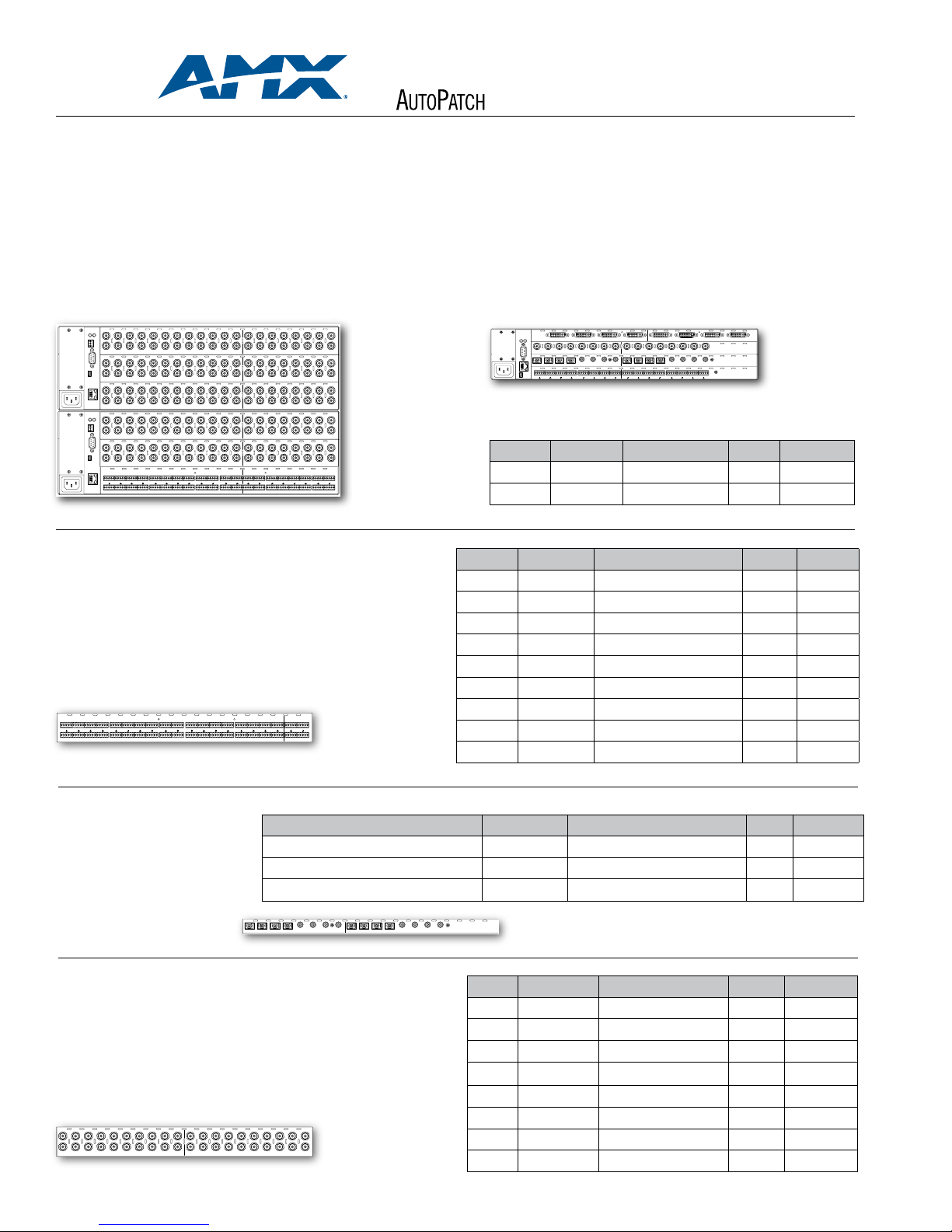
To customize an Optima Matrix Switcher simply mix and match from the available boards, add up the total slots those boards ll, and purchase enclosure(s) to accommodate that
total. For systems comprised of 2 or more linked enclosures, AutoPatch will provide a link cable or hub at no additional charge.*
Since each board has it’s own input and output connectors, the physical signal path must be routed from inputs on the board to outputs on the same board. For multiple component
signals, such as RGBHV, boards can then be combined in logical groups via software conguration (as shown in the RGBHV example below).
As always, our trained staff is available to provide free matrix design assistance. Please contact us at 800.622.0246 or 509.235.2636 if you have questions.
*A link cable is provided with two-enclosure systems, a hub and link cables are provided with systems that contain 3 or more linked enclosures.
OPTIMA 3 RU
Example Conguration (using 2, 3 RU enclosures)
24x16 Wideband (R)
24x16 Wideband (G)
24x16 Wideband (B)
24x16 Sync (H)
24x16 Sync (V)
24x16 Stereo Audio
AUDIO BOA RD LIS T
Standard Audio
(phoenix style connectors)
Designed for mono and stereo audio signals, all standard audio boards feature input gain control and output volume control accessible via front panel and RS-232.
Design Tip: The standard audio board connectors are designed for balanced stereo;
however, they can be wired for unbalanced stereo or balanced or unbalanced mono.
Shown here: 36x4 Standard Audio Board
OPTIMA 2 RU
Example Conguration
4x4 DVI
8x8 SD-SDI
8x8 TosLink , S/PDIF
8x8 Stereo
ENCLOSURE S
Rack Units FG # Model Slots List US$
2 FG1046-13 AVS-OP-ENC-BP-2U 4 Call
3 FG1046-10 AVS-OP-ENC-BP-3U 6 Call
I/O FG # Model Slots List US$
8x4 FG1046-539 AVS-OP-0804-AIO-ST-DVC-1S 1 Call
8x8 FG1046-494 AVS-OP-0808-AIO-ST-DVC-1S 1 Call
16x16 FG1046-533 AVS-OP-1616-AIO-ST-DVC-2S 2 Call
16x24 FG1046-548 AVS-OP-1624-AIO-ST-DVC-2S 2 Call
20x4 FG1046-473 AVS-OP-2004-AIO-ST-DVC-2S 2 Call
20x20 FG1046-416 AVS-OP-2020-AIO-ST-DVC-2S 2 Call
24x4 FG1046-500 AVS-OP-2404-AIO-ST-DVC-2S 2 Call
24x16 FG1046-434 AVS-OP-2416-AIO-ST-DVC-2S 2 Call
36x4 FG1046-425 AVS-OP-3604-AIO-ST-DVC-2S 2 Call
Digital Audio
Designed for S/PDIF and TosLink digital audio
signals, FG1046-461 can also convert between
S/PDIF and TosLink.
8x8 TosLink – optical connectors
8x8 S/PDIF – RCA connectors
8x8 TosLink , S/PDIF – optical RCA/connectors
Shown here: 8x8 TosLink , S/PDIF Board
VIDEO BOARD LIST
Standard Video (BNC connectors)
Designed for composite video and Y/c can also be used for S/PDIF (50 MHz)
Design Tip: Each board contains one BNC connection per input / output number. Thus, a
16x16 board contains 16 input BNC connections and 16 output BNC connections. Use two
16x16 boards to route 16x16 Y/c.
Shown here: 20x20 Standard Video Board
I/O FG # Model Slots List US$
FG1046-455 AVS-OP-0808-AOI-TOSLINK-1S 1 Call
FG1046-458 AVS-OP-0808-AIO-SPDIF-RCA-1S 1 Call
FG1046-461 AVS-OP-0808-AIO-TOSLINK-SPDIF-1S 1 Call
I/O FG # Model Slots List US$
8x8 FG1046-440 AVS-OP-0808-VIO-STD-1S 1 Call
16x16 FG1046-485 AVS-OP-1616-VIO-STD-2S 2 Call
16x24 FG1046-545 AVS-OP-1624-VIO-STD-2S 2 Call
20x4 FG1046-470 AVS-OP-2004-VIO-STD-2S 2 Call
20x20 FG1046-413 AVS-OP-2020-VIO-STD-2S 2 Call
24x4 FG1046-515 AVS-OP-2404-VIO-STD-2S 2 Call
24x16 FG1046-431 AVS-OP-2416-VIO-STD-2S 2 Call
36x4 FG1046-422 AVS-OP-3604-VIO-STD-2S 2 Call
Page 3

Optima COnfiguratiOn guide
IN
1 32 4 5 6 7 8
OUT
1 2 3 4 5 6 7 8
Y
C
Y
CC
IN
YCCY YCCY Y
CC
OUT
Y Y
1 32 4 5 6 7 8 1
CC
Y Y
CCC
Y Y YCCY Y
2 3 4 5 6 7 8
1413
IN
1 2
171615 1918
53 4 6 7
222120 2423
8 9 10 11 12
43
OUT
1 2
21
IN
5 6437
OUT
8
321
5 6 748
IN
1 32 4 5 6 7 8
OUT
1 2 3 4 5 6 7 8
IN
911110 12
32 4
13 14
5 6
1615
7 8
9
OUT
10
1 2 5
1311 12
3 4
14 15
6 7168
IN
1 32 4 5 6 7 8
OUT
1 2 3 4 5 6 7 8
VIDEO BOARD LIST (CON T.)
S-video (S-video connectors) Designed for S-video signals (50 MHz)
Shown here: 8x8 S-video Board
Y/c (BNC connectors) Designed for Y/c video signals (50 MHz)
Shown here: 8x8 Y/c Board
Wideband Video (BNC connectors)
Designed for RGB and RGsB, video signals (300 MHz)
Design Tip: Each board contains one BNC connection per input / output number.
Thus, a 20x20 board contains 20 input BNC connections and 20 output BNC
connections. Use three 20x20 boards to route 20x20 RGB. For RGBHV combine
wideband boards with sync boards.
Shown here: 24x4 Wideband Video Board
Wideband Video (HD-15 connectors)
Designed for RGBHV (300 MHz)
Shown here: 8x8 HD-15 Board
I/O FG # Model Slots List US$
8x8 FG1046-446 AVS-OP-0808-VIO-SVID-1S 1 Call
16x16 FG1046-488 AVS-OP-1616-VIO-SVID-2S 2 Call
I/O FG # Model Slots List US$
8x8 FG1046-476 AVS-OP-0808-VIO-YC-2S 2 Call
I/O FG # Model Slots List US$
8x8 FG1046-437 AVS-OP-0808-VIO-WB-1S 1 Call
16x16 FG1046-482 AVS-OP-1616-VIO-WB-2S 2 Call
16x24 FG1046-542 AVS-OP-1624-VIO-WB-2S 2 Call
20x4 FG1046-467 AVS-OP-2004-VIO-WB-2S 2 Call
20x20 FG1046-410 AVS-OP-2020-VIO-WB-2S 2 Call
24x4 FG1046-503 AVS-OP-2404-VIO-WB-2S 2 Call
24x16 FG1046-428 AVS-OP-2416-VIO-WB-2S 2 Call
36x4 FG1046-419 AVS-OP-3604-VIO-WB-2S 2 Call
I/O FG # Model Slots List US$
4x2 FG1046-530 AVS-OP-0402-VIO-HD15-1S 1 Call
8x4 FG1046-497 AVS-OP-0804-VIO-HD15-2S 2 Call
8x8 FG1046-536 AVS-OP-0808-VIO-HD15-2S 2 Call
15x15 FG1046-593 AVS-OP-1515-VIO-HD15-3S 3 Call
Sync (BNC connectors)
Designed for horizontal and vertical sync (H and V)
Design Tip: Each sync board contains one BNC connection per input / output
number (with the exception of the 8x8 board)+. Thus, a 20x4 board contains 20 input
connections and 4 output connections. Use two 20x4 boards to route 20x4 H and V.
+
The 8x8 sync board has H and V on the same board, thus it has 16 input connections
and 16 output connections. All other sync boards contain one BNC connection per
input / output number.
Shown here: 16x16 Sync Board
SD-SDI Digital Video (BNC connectors)
Design Tip: SD-SDI Conforms to SMPTE-259M, SMPTE-344M
Shown here: 8x8 SD-SDI Board
HD-SDI Digital Video (BNC connectors)
Design Tip: HD-SDI Conforms to SMPTE-259M, SMPTE-292M, SMPTE-344M.
Dual-link HD-SDI can be achieved by using two HD-SDI boards.
Shown here: 8x8 HD-SDI Board
I/O FG # Model Slots List US$
+
8x8
FG1046-443 AVS-OP-0808-SIO-HI-2S 2 Call
16x16 FG1046-569 AVS-OP-1616-SIO-HI-2S 2 Call
16x24 FG1046-566 AVS-OP-1624-SIO-HI-2S 2 Call
20x4 FG1046-470 AVS-OP-2004-VIO-STD-2S 2 Call
20x20 FG1046-560 AVS-OP-2020-SIO-HI-2S 2 Call
24x4 FG1046-515 AVS-OP-2404-VIO-STD-2S 2 Call
24x16 FG1046-554 AVS-OP-2416-SIO-HI-2S 2 Call
36x4 FG1046-422 AVS-OP-3604-VIO-STD-2S 2 Call
I/O FG # Model Slots List US$
4x4 FG1046-527 AVS-OP-0404-VIO-SDI-1S 1 Call
8x8 FG1046-491 AVS-OP-0808-VIO-SDI-1S 1 Call
I/O FG # Model Slots List US$
8x8 FG1046-590 AVS-OP-0808-VIO-SDI-HDSD-1S 1 Call
Page 4

Optima COnfiguratiOn guide
IN
21 3 4
OUT
1 2 3 4
DVI (DVI-I connectors)
Design Tip: DVI board is designed to route digital computer video. This board is not
HDCP compliant at this time.
I/O FG # Models Slots List US$
4x4 FG1046-479 AVS-OP-0404-VIO-DVI-1S 1 Call
Shown here: 4x4 DVI Board
PRO
CAT
Route and transmit uncompressed RGBHV + stereo audio up to 1,000 feet over category cable without worrying about exact cable measurements. Designed to route RGBHV and stereo inputs
out to CatPro (RJ-45) outputs; the Optima CatPro boards must be used with CatPro RGBHV + Stereo Receivers at each output destination device.
Shown here: 8x8 RGBHV + Stereo to CatPro Board
PRO
CAT
RGBHV + Stereo Receivers
Make precise gain, peak and skew adjustments in seconds. Each receiver features a simple dial, and LED indicator
for simple skew adjustments. A push of the dial and the LED illuminates with the color activated for adjustment (red,
green, or blue). And, white indicates stereo audio volume control. Gain and peak adjustments are also simple via
external potentiometers.
Description FG # Model Slots List US$
CatPro RGBHV + Stereo Receiver FG1010-48 AVB-RX-CATPRO-HD15-ST 2 Call
I/O FG # Model Slots List US$
4x8 FG1046-581 AVS-OP-0408-CATPRO-TX-RGBHV-STI 2 Call
8x8 FG1046-575 AVS-OP-0808-CATPRO-TX-RGBHV-STI 2 Call
Shown here: CatPro RGBHV + Stereo Receiver
CONT ROL PANE LS
All Optima enclosures include a standard RS-232 control port, are NetLinx® compatible, support AutoPatch’s simple BCS serial control protocol, ship with free APControl Software and are
compatible with all leading 3rd party control systems.
Listed here are front panel control options and our APWeb Expansion Board which provides a TCP/IP control interface. Only one panel is needed when multiple enclosures are linked together
to work as one system.
For more information on the capabilities of these control options as well as additional remote options please visit amx.com
or contact the factory.
**Currently the APWeb Expansion Board is available in the 3 RU enclosure only. It is also available as a stand alone external module.
3 RU MODEL S
Description FG # Model List US$
2 RU MODEL S
Description FG# Model List US$
8x8 CP-15 FG1046-261 AVS-OP-0808-CP15-2U Call
16x16 CP-15 FG1046-258 AVS-OP-1616-CP15-2U Call
16x24 CP-15 FG1046-255 AVS-OP-1624-CP15-2U Call
20x20 CP-15 FG1046-249 AVS-OP-2020-CP15-2U Call
24x16 CP-15 FG1046-252 AVS-OP-2416-CP15-2U Call
36x4 CP-15 FG1046-246 AVS-OP-3604-CP15-2U Call
8x8 CP-15 FG1046-240 AVS-OP-0808-CP15-3U Call
16x16 CP-15 FG1046-237 AVS-OP-0808-CP15-3U Call
16x24 CP-15 FG1046-234 AVS-OP-0808-CP15-3U Call
20x20 CP-15 FG1046-216 AVS-OP-2020-CP15-3U Call
24x16 CP-15 FG1046-231 AVS-OP-2416-CP15-3U Call
36x4 CP-15 FG1046-210 AVS-OP-3604-CP15-3U Call
CP-20A FG1046-213 AVS-OP-CP20A-3U Call
APWeb** FG1046-313 AVS-OP-TCPIP-3U Call
AUSTRALIA • BELGIUM • CANADA • CHINA • DUBAI • ENGLAND • FRANCE • GERMANY • GREECE
NETHERLANDS • NEW ZEALAND • PHILIPPINES • PORTUGAL • RUSSIA • SINGAPORE • SPAIN • SWITZERLAND
INDIANAPOLIS • LOS ANGELES • MINNEAPOLIS• PHILADELPHIA • PHOENIX • PORTLAND • SPOKANE • TAMPA
HONG KONG • INDIA • INDONESIA • ITALY • JAPAN • LEBANON • MALAYSIA
THAILAND • TURKEY • USA • ATLANTA • BOSTON • CHICAGO • CLEVELAND • DALLAS • DENVER
300 0 RE SEARC H DR IVE, RICH ARDS ON, T X 75 082 • 800. 222. 0193 • 46 9.624 .800 0
+1. 469. 624.7 400 • 469 .624 .7153 fax • ww w.amx .com
AMX Aut oPatc h Gr oup • 5 09.2 35.26 36 • 80 0.62 2.024 6
© 2007 AMX. All rights reserved. AMX and the AMX logo, AutoPatch and Optima are registered trademarks of AMX. AMX reserves the right to alter specications and pricing without notice at any time.
 Loading...