

INSTRUCTION MANUAL
™
ACENDO VIBE
ACV-2100 ACENDO VIBE™ CONFERENCING SOUNDBAR
ACV-5100 ACENDO VIBE™ CONFERENCING SOUNDBAR WITH CAMERA
IMPORTANT SAFETY INSTRUCTIONS
1. READ these instructions.
2. KEEP these instructions.
3. HEED all warnings.
4. FOLLOW all instructions.
5. DO NOT use this apparatus near water.
6. CLEAN ONLY with dry cloth.
7. DO NOT block any ventilation openings. Install in accordance with the manufacturer's instructions.
8. DO NOT install near any heat sources such as radiators, heat registers, stoves, or other apparatus (including amplifiers) that produce heat.
9. DO NOT defeat the safety purpose of the polarized or grounding type plug. A polarized plug has two blades with one wider than the other. A
grounding type plug has two blades and a third grounding prong. The wider blade or the third prong are provided for your safety. If the provided plug
does not fit into your outlet, consult an electrician for replacement of the obsolete outlet.
10. PROTECT the power cord from being walked on or pinched, particularly at plugs, convenience receptacles, and the point where they exit from the
apparatus.
11. ONLY USE attachments/accessories specified by the manufacturer.
12. USE ONLY with a cart, stand, tripod, bracket, or table specified by the manufacturer, or sold with the apparatus. When a cart is used, use caution
when moving the cart/apparatus combination to avoid injury from tip-over.
13. UNPLUG this apparatus during lightning storms or when unused for long periods of time.
14. REFER all servicing to qualified service personnel. Servicing is required when the apparatus has been damaged in any way, such as power-supply cord
or plug is damaged, liquid has been spilled or objects have fallen into the apparatus, the apparatus has been exposed to rain or moisture, does not
operate normally, or has been dropped.
15. DO NOT expose this apparatus to dripping or splashing and ensure that no objects filled with liquids, such as vases, are placed on the apparatus.
16. To completely disconnect this apparatus from the AC Mains, disconnect the power supply cord plug from the AC receptacle.
17. Where the mains plug or an appliance coupler is used as the disconnect device, the disconnect device shall remain readily operable.
18. DO NOT overload wall outlets or extension cords beyond their rated capacity as this can cause electric shock or fire.
The exclamation point, within an equilateral triangle, is intended to alert the user to the presence of impor tant operating and maintenance (servicing) instructions in
the literature accompanying the product.
The lightning flash with arrowhead symbol within an equilateral triangle is intended to alert the user to the presence of uninsulated "dangerous voltage" within the
product's enclosure that may be of sufficient magnitude to constitute a risk of electrical shock to persons.
ESD Warning: The icon to the left indicates text regarding potential danger associated with the discharge of static electricity from an outside source (such as human
hands) into an integrated circuit, often resulting in damage to the circuit.
WARNING: To reduce the risk of fire or electrical shock, do not expose this apparatus to rain or moisture.
WARNING: No naked flame sources - such as lighted candles - should be placed on the product.
WARNING: Equipment shall be connected to a MAINS socket outlet with a protective earthing connection.
WARNING: To reduce the risk of electric shock, grounding of the center pin of this plug must be maintained.
COPYRIGHT NOTICE
AMX© 2018, all rights reserved. No part of this publication may be reproduced, stored in a retrieval system, or transmitted, in any form or by any means, electronic,
mechanical, photocopying, recording, or otherwise, without the prior written permission of AMX. Copyright protection claimed extends to AMX hardware and software and
includes all forms and matters copyrightable material and information now allowed by statutory or judicial law or herein after granted, including without limitation, material
generated from the software programs which are displayed on the screen such as icons, screen display looks, etc. Reproduction or disassembly of embodied computer
programs or algorithms is expressly prohibited.
LIABILITY NOTICE
No patent liability is assumed with respect to the use of information contained herein. While ever y precaution has been taken in the preparation of this publication, AMX
assumes no responsibility for error or omissions. No liability is assumed for damages resulting from the use of the information contained herein. Further, this publication and
features described herein are subject to change without notice.
AMX WARRANTY AND RETURN POLICY
The AMX Warranty and Return Policy and related documents can be viewed/downloaded at www.amx.com.

3
Acendo Vibe Conferencing Soundbars - User Guide
Table of Contents
Acendo Vibe Conferencing Soundbars ............................................................... 5
Overview ............................................................................................................................ 5
ACV-5100 - Product Specifications ................................................................................. 5
Camera (ACV-5100 only)........................................................................................................... 5
ACV-2100 - Product Specifications ................................................................................ 6
Side Panel Keypad .................................................................................................................... 6
Volume and Mute Controls ....................................................................................................... 6
Bluetooth Pairing Button .......................................................................................................... 6
Remote Control.................................................................................................................. 7
Installing Batteries................................................................................................................... 7
Acendo Vibe Configuration Tool ......................................................................................... 7
Installing Acendo Vibe ....................................................................................... 8
Overview ............................................................................................................................ 8
Credenza Installation......................................................................................................... 8
Wall Mount Installation...................................................................................................... 8
Removing the Wall Mount Bracket ........................................................................................... 8
Wall Mount Considerations....................................................................................................... 8
Using the Bracket Mounting Guide ........................................................................................... 9
Mounting the Wall Mount Bracket and Attaching the Acendo Vibe ......................................... 10
Connections ..................................................................................................................... 11
ACV-5100 Connectors............................................................................................................. 11
ACV-2100 Connectors............................................................................................................. 12
Rotating the Acendo Vibe Into the Seated Position........................................................... 12
Installing Lock-Down Screws .......................................................................................... 13
Side Panel Keypad ........................................................................................................... 13
Volume and Mute Controls ..................................................................................................... 13
Camera (ACV-5100 only) .................................................................................................. 13
Remote Control................................................................................................................ 14
Pairing the Remote Control to the Acendo Vibe ..................................................................... 14
Pairing the Acendo Vibe with a Bluetooth Source Device ................................................. 14
Setting the Acendo Vibe as the Default Audio Device ....................................................... 14
Connecting RS232 for Serial Commands.......................................................................... 14
Connecting an External Motion Sensor
(future firmware update / ACV-5100 only) .................................................................... 15
Acendo Vibe Configuration Tool ....................................................................................... 15
Setup Mode............................................................................................................................. 15
Configuring Acendo Vibe Conferencing Sound Bars ........................................ 16
Overview .......................................................................................................................... 16
Downloading and Installing the Acendo Vibe Configuration Tool ..................................... 17

4
Acendo Vibe Conferencing Soundbars - User Guide
Connecting to the the Acendo Vibe via USB ...................................................................... 20
Accessing the USB Connector................................................................................................. 20
Entering Setup Mode........................................................................................................ 21
Exiting Setup Mode ................................................................................................................. 21
USB Connected Window ................................................................................................... 21
Transfer Options Window................................................................................................. 22
Bluetooth Configuration Options...................................................................................... 22
Events Configuration Options (ACV-5100 only) ................................................................ 23
Audio Configuration Options ............................................................................................ 24
File Options (Open, Save and Transfer)............................................................................ 25
Opening an Existing Acendo Vibe Configuration File .............................................................. 25
Saving Settings as an Acendo Vibe Configuration File ............................................................ 26
Transfer settings from this file .............................................................................................. 27
Viewing/Modifying an Acendo Vibe Configuration File............................................................ 27
Sending New Settings to Acendo Vibe..................................................................................... 28
Getting Current Settings From Acendo Vibe........................................................................... 29
Sending Firmware Update to Acendo Vibe.............................................................................. 29
Serial Commands ............................................................................................ 31
Overview .......................................................................................................................... 31
RS-232 Connector Specifications............................................................................................ 31
Command Protocol .......................................................................................................... 31
Protocol Definition.................................................................................................................. 31
Syntax................................................................................................................................................ 31
Case Sensitivity ................................................................................................................................. 31
Path Syntax........................................................................................................................................ 31
Command / Reply .............................................................................................................................. 31
Parameters ....................................................................................................................................... 31
Unsupported command reply ............................................................................................................ 31
Getting and setting values ...................................................................................................... 32
Paths ................................................................................................................................................. 32
Execute command ............................................................................................................................. 32
Get value............................................................................................................................................ 32
Set value............................................................................................................................................ 32
Errors..................................................................................................................................... 33
Error reply ........................................................................................................................................ 33
Unrecognized command reply ........................................................................................................... 33
Events..................................................................................................................................... 33
Serial Commands............................................................................................................. 33
Serial Commands - ACV-2100 & ACV-5100............................................................................. 33
Serial Commands - ACV-5100 ONLY ....................................................................................... 35
Events .............................................................................................................................. 38
Troubleshooting .............................................................................................. 39
5
Acendo Vibe Conferencing Soundbars - User Guide
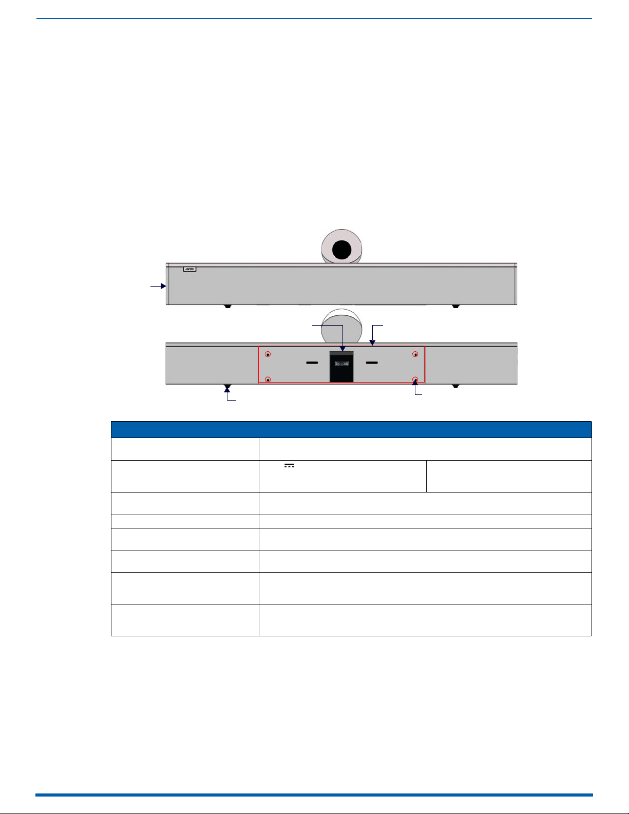
Acendo Vibe Conferencing Soundbars
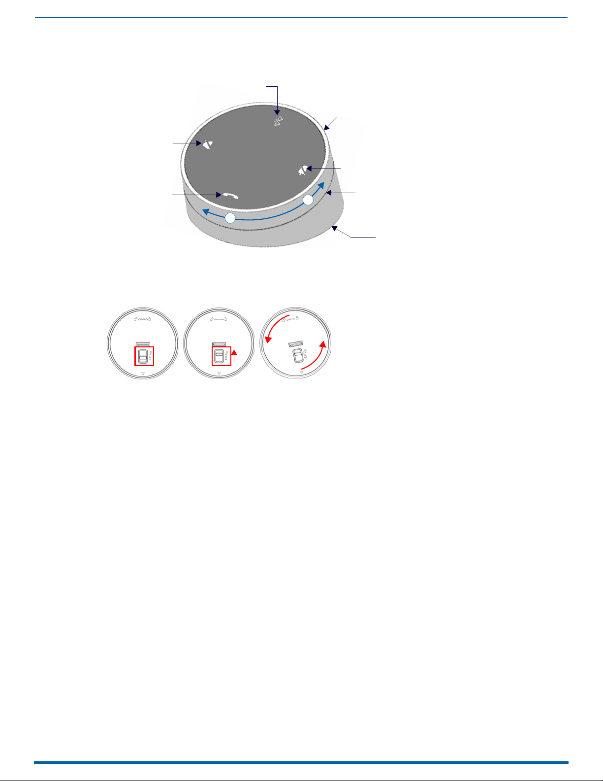
Camera
Front
Rear
Rubber feet (removable, x2)
mounting holes (x4)
Wall Mount Bracket
Side Panel
Keypad
Cable Pass-Thru
Overview
The ACV-2100 and ACV-5100 Acendo Vibe™ Conferencing Sound Bars are expertly designed web conferencing sound
bars featuring USB and Bluetooth
outputs allow the Acendo Vibe to easily integrate with other room technology.
The ACV-5100 Acendo Vibe Conferencing Sound Bar with Camera also features an integrated wide-angle camera and
HDMI inputs and outputs with CEC display control.
Both Acendo Vibes feature a connector bay door that also serves as a hinged Wall Mount Bracket, which allows easy
access to the connector bay without having to dismount the unit. The Wall Mount Bracket features a cutout for cable
routing and straps for cable management.
ACV-5100 - Product Specifications
®
connectivity support for BYOD environments. Dedicated analog audio inputs and
Acendo Vibe Conferencing Soundbars
FIG. 1
ACV-5100 (Front/Rear views)
ACV-5100 Product specifications
MODELS AVAILABLE • ACV-5100GR, Grey (FG4151-00GR)
INCLUDED ACCESSORIES • 15V / 4A.Power Supply
DIMENSIONS (HWD) • 5" x 23 1/2" x 3 15/16" (76 mm x 590 mm x 100 mm)
WEIGHT 6.45 lbs (2.93 kg)
ACTIVE POWER REQUIREMENTS • ~100-240V, 1.3A max
REGULATORY COMPLIANCE FCC 47 CFR Part 15, Subpart C / Subpart B (emissions)
ENVIRONMENTAL • Temperature (Operating): 32° F to 11 3° F (0° C to 45° C)
OPTIONAL ACCESSORIES • CBL-USB-FL2-16, USB 2.0 16ft Extension Cable (FG10-2220-16)
Camera (ACV-5100 only)
The ACV-5100 is equipped with a wide-angle camera for videoconferencing and supports a wide range of web
conferencing applications via its USB port. Refer to the Camera (ACV-5100 only) section on page 13 for details.
NOTE: To adjust the camera’s view, simply grasp the camera and rotate to the desired position.
• ACV-5100BL, Black (FG4151-00BL)
•Remote Control
•6’ USB 2.0 Cable
• Depth with optional wall mount spacers: 4 1/8” (105 mm)
• Only use the included power supply
EN 55024, EN 60950-1, IEC/EN/UL 60065:2014
• Temperature (Storage): -4° F to 158° F (-20° C to 70° C)
• Humidity (Operating): 5% to 85% RH non-condensing
• CBL-USB-FL2-33, USB 2.0 33ft Extension Cable (FG10-2220-33)
• ACR-5100, Meeting Collaboration System (FG4051-00)
• 5mm Wall Mount Spacers (4)
•Lock-Down Screws (2)
Acendo Vibe Conferencing Soundbars
6
Acendo Vibe Conferencing Soundbars - User Guide
Front
Rear
mounting holes (x4)
Wall Mount Bracket
Rubber feet (removable, x2)
Side Panel
Keypad
Cable Pass-Thru
Active Audio Source
Audio Source Select
(press to cycle through
the source options)
Mute Speaker
Mute Microphone
Volu me Up/Down
Bluetooth Pairing
(indicates the
current selection
ACV-2100 - Product Specifications
FIG. 2
ACV-2100 (Front/Rear views)
ACV-2100 Product specifications
MODELS AVAILABLE • ACV-2100GR, Grey (FG4121-00GR)
INCLUDED ACCESSORIES • 15V / 4A.Power Supply
DIMENSIONS (HWD) • 3" x 23 1/2" x 3 15/16" (76 mm x 590 mm x 100 mm)
WEIGHT 6.3 lbs (2.86 kg)
ACTIVE POWER REQUIREMENTS • ~100-240V, 1.3A max
REGULATORY COMPLIANCE FCC 47 CFR Part 15, Subpart C / Subpart B (emissions)
ENVIRONMENTAL • Temperature (Operating): 32° F to 11 3° F (0° C to 45° C)
OPTIONAL ACCESSORIES • CBL-USB-FL2-16, USB 2.0 16ft Extension Cable (FG10-2220-16)
• ACV-2100BL, Black (FG4121-00BL)
•Remote Control
•6’ USB 2.0 Cable
• Depth with optional wall mount spacers: 4 1/8” (105 mm)
• Only use the included power supply
EN 55024, EN 60950-1, IEC/EN/UL 60065:2014
• Temperature (Storage): -4° F to 158° F (-20° C to 70° C)
• Humidity (Operating): 5% to 85% RH non-condensing
• CBL-USB-FL2-33, USB 2.0 33ft Extension Cable (FG10-2220-33)
• ACR-5100, Meeting Collaboration System (FG4051-00)
• 5mm Wall Mount Spacers (4)
•Lock-Down Screws (2)
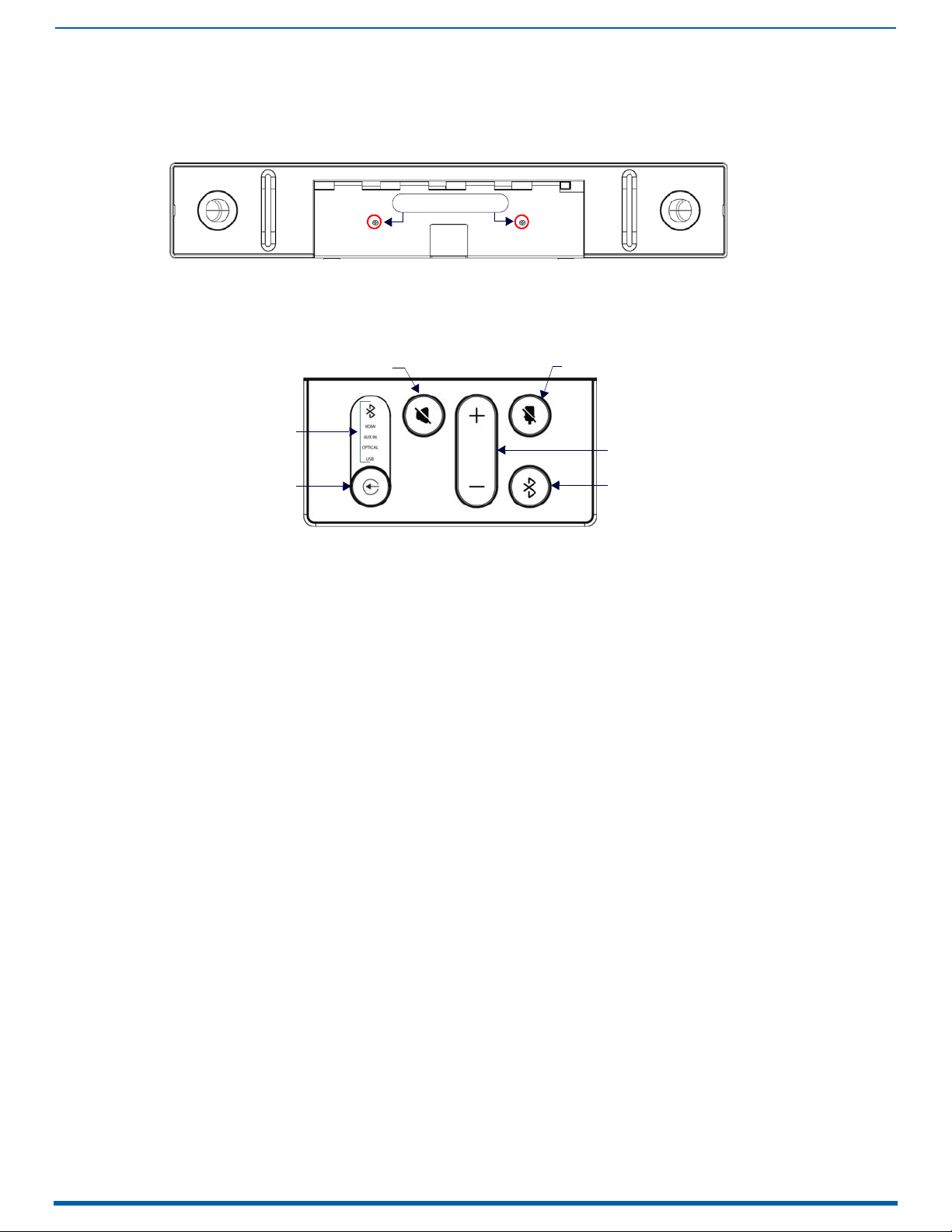
Side Panel Keypad
All controls and LEDs are on the left side panel of the Acendo Vibe (FIG.3):
FIG. 3 Acendo Vibe LEFT SIDE PANEL Keypad
Volume and Mute Controls
Use the Volume Up/Down buttons to adjust speaker volume.
Mute Speaker and Mute Microphone enable/disable the speakers and microphone. Note that these buttons
illuminate to indicate when the sound functions are muted.
Bluetooth Pairing Button
Use this button for pairing the Acendo Vibe with a Bluetooth source device. For instructions, refer to the Pairing the
Acendo Vibe with a Bluetooth Source Device section on page 14.
Acendo Vibe Conferencing Soundbars
7
Acendo Vibe Conferencing Soundbars - User Guide
Bluetooth Pairing
Mute Microphone
Mute Speaker
End Call
Source Select pushbutton (on back side)
(press to pair remote to user device)
Volume Up/ Down
+
-
(rotate ring to adjust)
Battery Compartment (bottom panel)
Unlock & twist to open
Remote Control
The Acendo Vibe includes a color matched remote control that connects wirelessly (FIG. 4):
Acendo Vibe Remote Control
FIG. 4
Installing Batteries
1. Remove the bottom panel of the remote control to access the battery compartment:
2. On the bottom panel, flip the plastic lock to the Unlocked position (FIG. 5 ):
FIG. 5 Remote control - bottom panel (lock/unlock/remove)
3. Rotate the bottom panel to the left and lift to remove.
4. Insert two AA batteries.
5. Replace and lock the bottom panel.
For details and instructions on pairing the remote control to the Acendo Vibe see page 14.
Acendo Vibe Configuration Tool
Both Acendo Vibe Sound Bars are configured via the Acendo Vibe Configuration Tool software (available to download
from AMX). In most cases the default settings should work fine without any need for adjustment. Configurable settings
include:
Bluetooth (On/Off) - Click to toggle On/Off (default = On).
Bluetooth Device Name - Enter a new name for the Acendo Vibe unit. This is the device name for the Acendo Vibe
when discovered via Bluetooth (default = "Acendo Vibe").
Events (ACV-5100 only) - Configure how CEC display control operates relative to defined events, and adjust
Occupancy Sensor settings (see page 15).
Aux Out Gain - Select Variable (default) or Fixed.
Default Volume - Enter a value for the default output volume (default = 50, valid for all audio sources).
Automatic Audio Switching - Toggle On/Off (default = On).
Us e the File (Open, Save and Transfer) options to save the current settings, open an existing config file, and transfer
the current settings to an Acendo Vibe via USB connection.
For details, see the Configuring Acendo Vibe Conferencing Sound Bars section on page 16.
8
Acendo Vibe Conferencing Soundbars - User Guide
Installing Acendo Vibe
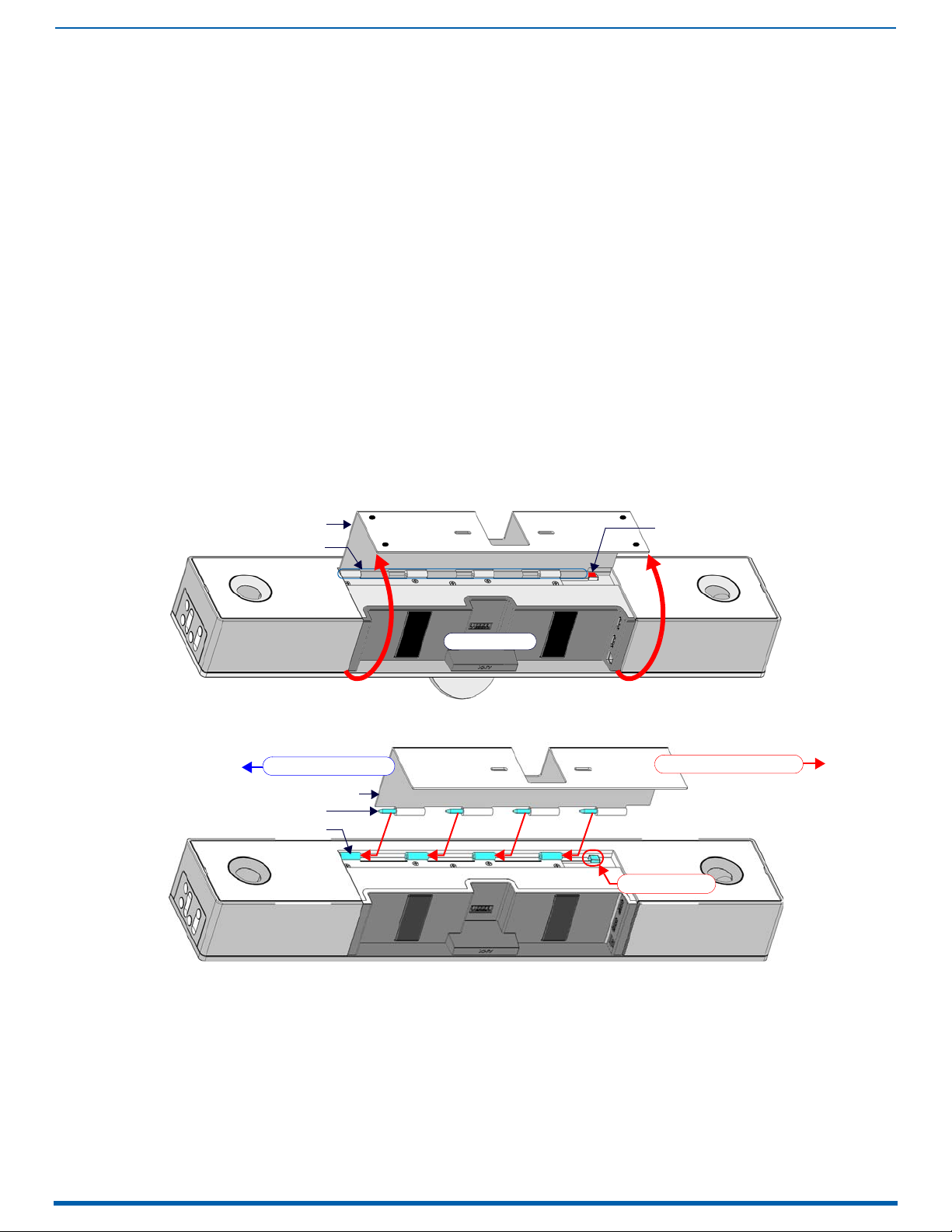
Wall Mount Bracket
Hinges/Pins
Release Button
connector bay
Wall Mount Bracket
Pins (x4)
Hinges (x4)
Slide pins in to install
Slide pins out to remove
Release Button
Overview
This section describes the physical installation of the Acendo Vibe unit. Note that many of the mounting illustrations use
the ACV-5100 as an example, but these mounting instructions apply equally to the ACV-2100.
NOTE: Do not lift the ACV-5100 by the camera or rest the ACV-5100 unit on the camera.
Credenza Installation
NOTE: To ensure highest possible sound quality, the rubber feet on the bottom panel must remain in place for surface-
mount installations.
The Acendo Vibe can sit on a hard, flat surface such as a credenza, tabletop or desk. When choosing a surface location,
consider a space that will not interfere with workspaces or other installed devices. Connect cables as necessary - see the
Connections section on page 11 for details.
Wall Mount Installation
For best aesthetic in wall mount installations, remove the rubber feet from the bottom panel: carefully peel each foot off
of the bottom surface.
Removing the Wall Mount Bracket
1. Open the Wall Mount Bracket (held closed by internal magnets).
2. Press and hold the Release Button to slide the Bracket out (over the button) to disengage the pins on the Bracket
from the hinges on the unit (FIG. 6).
Installing Acendo Vibe
FIG. 6
Acendo Vibe Bottom View - opening the wall mount bracket
3. Lift the Wall Mount Bracket off of the hinges to remove (FIG. 7):
FIG. 7 Acendo Vibe Bottom View - removing the bracket
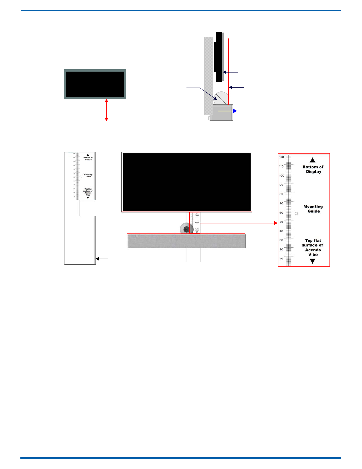
Wall Mount Considerations
Distance between conference table and display: The closer the table is to the wa ll-mounted display . the lower the
display should be mounted. As a general guide, the display should be mounted between 40” and 48” from the
floor (see FIG. 8 on page 9).
Avoid obstructing the camera view: If the display protrudes from the wall more than the Acendo Vibe, then
additional spacing between the display and the Acendo Vibe may be needed.
Position camera for full visibility: In small rooms, it may be necessary to manually tilt the camera up to maximize
visibility for all participants.
Installing Acendo Vibe
9
Acendo Vibe Conferencing Soundbars - User Guide
40-48” from floor
Camera lens should be
positioned beyond the display
to avoid obstructing the view
Display
Acendo Vibe Camera
Display
front
(side view)
Mounting Bracket
Mounting Guide
(etched into surface)
(top view)
Acendo Vibe
Display
Acendo Vibe Wall Mount Considerations
FIG. 8
Using the Bracket Mounting Guide
The Wall Mount Bracket features instructions etched on the inner surface that describe how to position the Acendo Vibe
beneath a wall-mounted display to avoid obstructing the camera view (FIG. 9):
FIG. 9 Using The Mounting Guide
1. Remove the Bracket from the Acendo Vibe (see FIG. 7 on page 8).
2. Turn the Bracket vertically and place against the wall, centered directly beneath the wall-mounted display.
3. Align the top of the Bracket (see Bottom of Display) with the bottom surface of the display.
4. Use the top edge of the notch in the Bracket (see Top flat surface of Acendo Vibe to determine the closest
placement for the Acendo Vibe beneath the display. Mark the mounting surface.
5. Align the top flat surface of the Acendo Vibe with the mark made in step 4.
6. Mount the Bracket using mounting screws and optional mounting spacers (see FIG. 10).
Installing Acendo Vibe
10
Acendo Vibe Conferencing Soundbars - User Guide
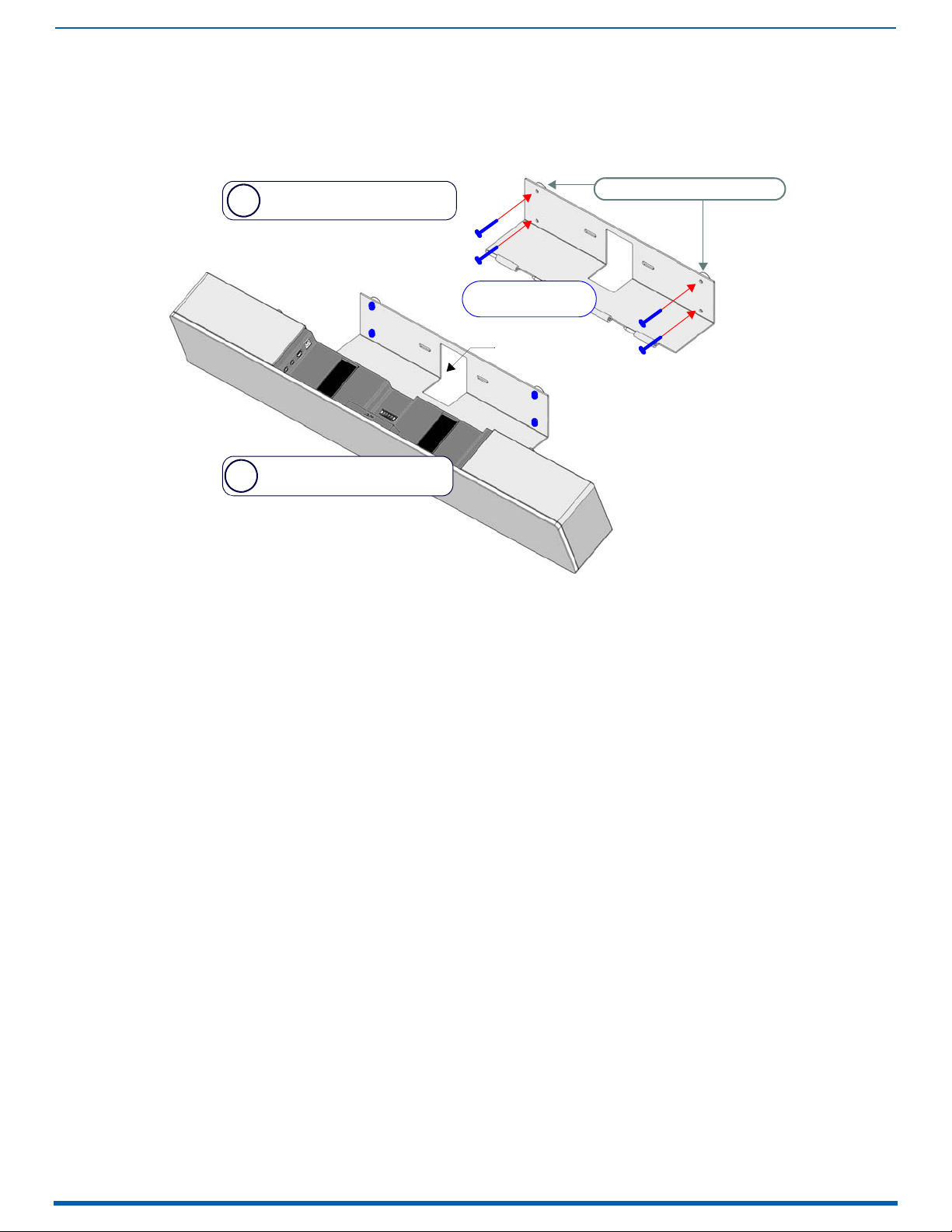
Mount the Bracket to the
wall via 4 mounting screws
Attach the Acendo Vibe to the
Bracket via hinges & pins
b
a
mounting screws
(x4, not included)
mounting spacers (x4, optional)
Note: Use M4 or #8 mounting screws
Cable Pass-Thru
Mounting the Wall Mount Bracket and Attaching the Acendo Vibe
1. Use the Wall Mount Bracket as a template to mark the locations for the four mounting screws (not included). Use
mounting screws and hardware appropriate for the surface being utilized to secure the Bracket to the wall.
Optionally, if not hiding them behind the drywall, place the four included Wall Mount Spacers between the Bracket
and the wall to create a 5mm gap for routing flat cables (FIG. 10).
FIG. 10
2. Attach the Acendo Vibe to the Bracket by sliding the pins on the Bracket into the hinges on the rear of the main unit
3. Connect cables as necessary (inside the connector bay - see FIG. 11 on page 11 and FIG. 12 on page 12).
4. Rotate the Acendo Vibe into seated position. The Bracket is secured with magnets (FIG. 13).
Wall Mounting the Acendo Vibe
(see FIG. 7):
a. Position the Acendo Vibe with the bottom panel facing the wall and align the hinges on the main unit with the
pins on the Bracket.
b. Carefully slide the pins into the hinges, until the Bracket snaps into place.
Note: Press the Bracket into place so that the last pin depresses the Release Button, allowing the pins to slide into
the hinges (see FIG. 7)
c. With the Acendo Vibe attached to the Bracket, rotate the unit up to its seated position. Note that the Bracket
snaps shut and is held closed via internal magnets.
Note: Ensure that cables do not obstruct the complete closing of the unit.
Installing Acendo Vibe
11
Acendo Vibe Conferencing Soundbars - User Guide
Analog audio input
Analog audio output
Optical audio input
DC Power input
USB (Type B)
HDMI Input (from source device)
cable strap cable strap
RS-232 (3-pin captive wire - for Serial communication)
HDMI Output (to display)
MOTION (3-pin captive wire)
(future firmware upgrade)
Connections
All connectors are located within the connector bay (rear panel).
For surface installations, place the unit face-down and open the connector bay door to manage
cables/connectors.
For wall-mounted installations, simply rotate the Acendo Vibe unit down and away from the wall to access the
connector bay.
There are two sets of connectors on the inner side panels of the connector bay. Each connector is labeled on the elastic
cable straps. Run each cable through the cable pass-thru in the bracket/door and under the cable straps.
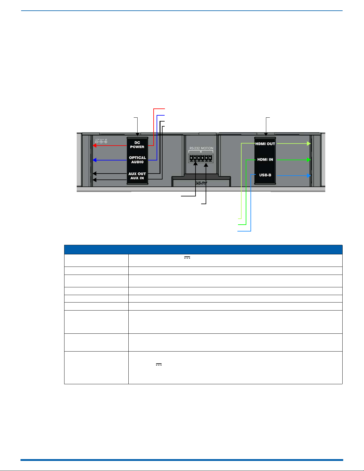
ACV-5100 Connectors
The connectors on the ACV-5100 are shown in FIG. 11: .
FIG. 11
ACV-5100 connector bay
ACV-5100 Connections
DC POWER Connect the included 15V power supply to this barrel connector. Only use the power supply included
OPTICAL AUDIO Use this TOSLINK connector to receive Optical Stereo Input from an audio source device.
AUX OUT Use this 1/8” mini-stereo connector to send analog stereo sound from the Acendo Vibe to an auxiliary
AUX IN Use this 1/8” mini-stereo connector to receive analog stereo sound from an analog audio source device.
HDMI OUT (Type A) Connect to an HDMI input on a display device.
HDMI IN (Type A) Connect to an HDMI output from a source device, such as a laptop or Acendo Core.
USB Use the USB 2.0 Type-B port to connect a PC/laptop to the Acendo Vibe as a source device.
RS-232 3-pin captive-wire connector provides serial communication with the Acendo Vibe. Refer to the Serial
MOTION
(future firmware upgrade)
Run each cable through the cable pass-thru in the bracket/door and under the cable strap
with the ACV-5100.
device.
Acendo Vibe is plug-and-play with PC/laptop using standard UAC/UVC drivers.
The USB connection is also used to configure the Acendo Vibe via the Acendo Vibe Configuration Tool
for settings and firmware updates.
Commands section on page31 for command definitions.
The Baud Rate for the RS-232 connector is 115200.
3-pin captive-wire connector provides connectivity for an (optional) motion sensor (reserved for future
implementation):
•PWR (+5V 0.1A)
•OCC
•Ground
The logic of OCC is "High" for occupancy detected, and "Low" for vacancy.
12
Acendo Vibe Conferencing Soundbars - User Guide
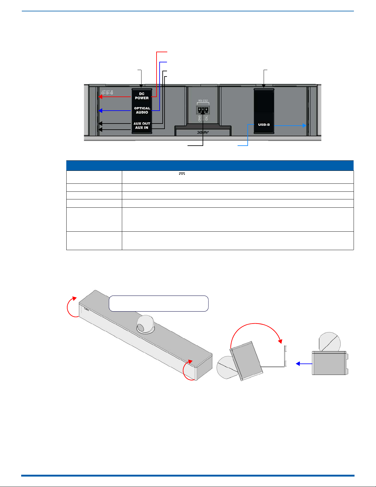
ACV-2100 Connectors
Analog audio input
Analog audio output
Optical audio input
DC Power input
USB (Type B)
cable strap
cable strap
RS-232 (3-pin captive wire)
Rotate the Acendo Vibe into seated position
(Bracket is secured with magnets)
front
open closed
The connectors on the ACV-2100 are shown in FIG. 12: .
Installing Acendo Vibe
FIG. 12
ACV-2100 connector bay
ACV-2100 Connections
DC POWER Connect the included 15V power supply to this barrel connector. Only use the power supply included with
OPTICAL AUDIO: Use this TOSLINK connector to receive Optical Stereo Input from an audio source device.
AUX OUT Use this 1/8” mini-stereo connector to send analog stereo sound fr om th e ACV -210 0 to an auxili ary de vic e.
AUX IN Use this 1/8” mini-stereo connector to receive analog stereo sound from an analog audio source device.
USB Use the USB 2.0 Type-B por t to connect a PC/laptop to the ACV-2100 as a source device.
RS-232 3-pin captive-wire connector provides serial communication with the Acendo Vibe. Refer to the Serial
Run each cable through the cable pass-thru in the bracket/door and under the cable strap.
the ACV-2100.
Acendo Vibe is plug-and-play with PC/laptop using a standard UAC driver.
The USB connection is also used to configure the ACV-2100 via the AMX Acendo Vibe configuration
application and for file transfers.
Commands section on page 31 for command definitions.
The Baud Rate for the RS-232 connector is 115200.
Rotating the Acendo Vibe Into the Seated Position
After connecting all cables, close the Bracket to return the Acendo Vibe to its seated position. The Bracket is secured via
internal magnets (FIG. 13):
FIG. 13 Rotating the Acendo Vibe into its seated position
Installing Acendo Vibe
13
Acendo Vibe Conferencing Soundbars - User Guide
Lock-Down Screws
Active Audio Source
Audio Source Select
the source options)
Mute speaker
Mute Microphone
Volume Up/Down
Bluetooth Pairing
(indicates the
current selection
Installing Lock-Down Screws
The Acendo Vibe comes with two (flat-head) Lock-Down Screws that can be added after the Acendo Vibe has been
installed and connected. The Lock-Down Screws prevent the Bracket from being opened accidentally. With the Bracket/
connector bay door closed, install the Lock-Down Screws in the bottom panel (FIG. 14):
FIG. 14
NOTE: The Lock Down screws are not to be used to mount the Acendo Vibe unit to the wall.
Acendo Vibe Bottom View - Lock Down Screw Locations
Side Panel Keypad
All controls and LEDs are on the left side panel of the Acendo Vibe (FIG. 15):
FIG. 15 Acendo Vibe LEFT SIDE PANEL Keypad
Volume and Mute Controls
The Acendo Vibe features Sound by JBL, including a 10W/channel stereo amplifier, speakers, microphones, and DSP
algorithms with AEC
Use the Volume Up/Down buttons on either the Acendo Vibe side panel or on the remote control to adjust speaker
volume.
Mute Speaker and Mute Microphone enable/disable the speakers and microphone. Note that these buttons are lit
on the Acendo Vibe (and flash on the remote control) to indicate that the sound functions are muted.
Camera (ACV-5100 only)
The ACV-5100 is equipped with a wide-angle camera for videoconferencing and supports a wide range of web
conferencing applications via USB. To configure your USB device, such as a laptop, to work with the Acendo Vibe:
1. Connect the Acendo Vibe to a laptop/PC via USB.
2. Use Source Select button on the the Acendo Vibe (FIG. 15) to select USB (if necessary).
3. Select AMX Acendo Vibe as the camera.
4. Select AMX Acendo Vibe as the microphone.
5. Select USB AUDIO CODEC as the speakers.
NOTE: To adjust the camera’s view, simply grasp the camera and rotate to the desired position.

14
Acendo Vibe Conferencing Soundbars - User Guide
Remote Control
Bluetooth Pairing
Mute Microphone
Mute Speaker
End Call
Source Select pushbutton (on back side)
Volume Up/Down (rotate ring to adjust)
+
-
Battery Compartment (bottom panel)
Unlock & twist to open
Source Select (press to
cycle through source options)
Bluetooth Pairing
The Acendo Vibe includes a wireless remote control (FIG. 16):
Installing Acendo Vibe
FIG. 16
Acendo Vibe Remote Control
Pairing the Remote Control to the Acendo Vibe
FIG. 17 Acendo Vibe LEFT SIDE PANEL Keypad
1. Press and hold both the Source Select and Bluetooth Pairing buttons on the remote control for 5 seconds (see
FIG. 16). All LEDS on the remote control should start blinking or remain blinking (once per second).
2. Press and hold both the Source Select and Bluetooth Pairing buttons on the Acendo Vibe (see FIG. 15). After 3-5
seconds the LEDS on the remote control should stop flashing to indicate the remote control has paired.
NOTE: If the remote control remains in pairing mode (all LEDS blinking) for longer than 60 seconds the remote control will
go to sleep. Press any button on the remote control to wake it up and continue with step 2.
Pairing the Acendo Vibe with a Bluetooth Source Device
1. Press the Bluetooth Pairing button on the Acendo Vibe or the remote control to initiate pairing (see FIG. 15). The
Bluetooth button will flash on both the Acendo Vibe and the remote control.
NOTE: To exit pairing mode without pairing a device, press either Bluetooth button again for 5 seconds.
2. On the source device, verify that Bluetooth pairing is enabled, and look for “Acendo Vibe” (or custom discoverable
name) as a found device. Select the Acendo Vibe device for pairing.
The Bluetooth LED on the Acendo Vibe side panel lights solid to indicate that the device is paired.
If automatic switching is disabled, use the Source Select button on the Acendo Vibe to select Bluetooth as the audio
source (if necessary). At this point, the Bluetooth LED is lit solid, Bluetooth audio is sent to the Acendo Vibe speakers,
and microphone audio is sent to the paired Bluetooth device.
NOTE: Once the Acendo Vibe has paired to a device, it must either be "removed" or "forgotten" from your device’s
Bluetooth pairing list before it can be paired again.
Setting the Acendo Vibe as the Default Audio Device
The Acendo Vibe can be set to be the default device for audio playback as well as recording and camera (Acendo Vibe
only) on a PC/laptop/mobile device. This setting must be performed manually via the device’s sound options.
Connecting RS232 for Serial Commands
Both Acendo Vibes feature a 3-pin captive-wire RS-232 connector that provides support for the Serial commands
described in the Serial Commands section on page 31.
The RS-232 connector is located in the center of the Connector Bay (see FIG. 11 on page 11).
TXD
RXD
GND

Installing Acendo Vibe
15
Acendo Vibe Conferencing Soundbars - User Guide
Connecting an External Motion Sensor (future firmware update / ACV-5100 only)
The ACV-5100 features a 3-pin captive-wire connector that provides connectivity for the future implementation of an
(optional) motion sensor, located next to the RS-232 connector (see FIG. 11 on page 11).
+5V
DET (for Detect)
Ground
The logic of DET is "High" for occupancy detected, and "Low" for vacancy.
Acendo Vibe Configuration Tool
The Acendo Vibe is configured via the Acendo Vibe Configuration Tool software (available to download from AMX). In
most cases the default settings should not require adjustment. For details, see the Acendo Vibe Instruction Manual,
available to view or download from www.amx.com.
Setup Mode
In order for the Acendo Vibe Configuration Tool to communicate with the Acendo Vibe, the unit must be in Setup Mode.
See the Entering Setup Mode section on page 21 for details.

Configuring Acendo Vibe Conferencing Sound Bars
16
Acendo Vibe Conferencing Soundbars - User Guide
Side Menu Bar
Software version information
Firmware version information
Configuring Acendo Vibe Conferencing Sound Bars
Overview
The ACV-2100/5100 Acendo Vibe Conferencing Sound Bars are configurable via the Acendo Vibe Configuration Tool
software (available to download from www.amx.com). Note that there are two versions of the configuration software tool
- one for PC and one for Mac.
NOTE: This document uses the Windows version of the software for illustration purposes, however the Mac version works
identically.
The Acendo Vibe Configuration Tool organizes settings into four categories: Bluetooth, Events (ACV-5100 model only),
Audio and File, as indicated in the Side menu bar along the left side of the application window (FIG. 18):
FIG. 18
NOTE: In most cases the default settings should work fine without any need for adjustment. However, as part of the initial
installation process, it is necessary to use the configuration software tool to commission each Acendo Vibe unit.
The Acendo Vibe unit must be in Setup Mode in order to communicate with the Acendo Vibe Configuration Tool. See the
Entering Setup Mode section on page 21 for details.
Acendo Vibe Configuration Tool (Bluetooth options shown)
Bluetooth options are described on page22.
Events options are described on page23.
Audio options are described on page 24.
File options are described on page 25.

Configuring Acendo Vibe Conferencing Sound Bars
17
Acendo Vibe Conferencing Soundbars - User Guide
Downloading and Installing the Acendo Vibe Configuration Tool
Go to the ACV-2100 or ACV-5100 product pages on the AMX Trade site and click the Acendo Vibe Configuration
Software link to download the installation file.
1. Download the installation file to a known location.
2. Double-click the installation (*.exe) file and follow the on-screen directions to install:
a. In the Welcome to the Acendo Vibe Setup Wizard dialog, click Next to proceed (FIG. 19):
FIG. 19
FIG. 20 Acendo Vibe Setup Wizard - License Agreement dialog
Welcome to the Acendo Vibe Setup Wizard dialog
b. Read and accept the License Agreement, and click Next to proceed (FIG. 20):
c. Select a destination folder for this installation (or leave the default folder setting) and click Next to proceed
(FIG. 21):
FIG. 21 Acendo Vibe Setup Wizard - Select Destination Location dialog
d. Select a Start Menu folder folder for this installation (or leave the default folder setting) and click Next to proceed
(FIG. 22):

Configuring Acendo Vibe Conferencing Sound Bars
18
Acendo Vibe Conferencing Soundbars - User Guide
FIG. 22
Acendo Vibe Setup Wizard - Select Start Menu Folder dialog
e. By default, the installation will create a desktop shortcut: de-select this option if desired and click Next to
proceed (FIG. 23):
FIG. 23 Acendo Vibe Setup Wizard - Select Additional Tasks
f. In the Ready to Install dialog, click Install (FIG. 24):
FIG. 24 Acendo Vibe Setup Wizard - Ready to Install dialog
3. This selection invokes the first of two Device Driver Installation Wizards (FIG. 25). These Wizards install the two device
drivers required by the Acendo Vibe.

Configuring Acendo Vibe Conferencing Sound Bars
19
Acendo Vibe Conferencing Soundbars - User Guide
FIG. 25
Device Driver Installation Wizard (1 of 2) - Welcome dialog
4. Click Next to proceed (FIG. 26):
FIG. 26 Device Driver Installation Wizard (1 of 2) - Completing the Device Driver Installation Wizard dialog
5. Click Finish to close this dialog and open a second Device Driver Installation Wizard that installs the second device
driver (FIG. 27):
FIG. 27 Device Driver Installation Wizard (2 of 2) - Completing the Device Driver Installation Wizard dialog
6. Click Finish to close the Device Driver Installation Wizard and return to the final Acendo Vibe Setup Wizard dialog
(FIG. 27):

Configuring Acendo Vibe Conferencing Sound Bars
20
Acendo Vibe Conferencing Soundbars - User Guide
elastic cable strap
USB port
(Type B)
To PC
FIG. 28
Acendo Vibe Setup Wizard - Completing the Acendo Vibe Setup Wizard
Note that by default, both options in this dialog are selected:
View Readme.txt - When the Finish button is clicked, the release notes for this release are opened.
Launch Acendo Vibe 1.x.x - When the Finish button is clicked, the Acendo Vibe Configuration Tool is launched
automatically.
7. Click Finish to close the Setup Wizard. Assuming that the options above are selected , the Readme.txt f ile is displayed,
and the Acendo Vibe Configuration Tool is launched.
NOTE: Assuming that the Acendo Vibe is not yet connected to to the PC running the Configuration Tool via USB, the Setup
Mode window (see FIG. 31 on page 21) is presented.
Connecting to the the Acendo Vibe via USB
The Acendo Vibe Configuration Tool communicates with the Acendo Vibe via the USB port.
NOTE: It is not necessary to have an Acendo Vibe connected to the PC to use the Configuration Tool. The software
provides the ability to create and save configuration (*.json) files, and then transfer them to one or more Acendo Vibe
units at a later time. See the File Options (Open, Save and Transfer) section on page 25 for details.
Accessing the USB Connector
For surface installations, place the unit face-down and open the Connector Bay Doo r to manage cables/
connectors.
For wall-mounted installations, rotate the Acendo Vibe unit down and away from the wall to access the
Connector Bay. The USB-B port is labeled on the elastic cable strap (FIG. 29): .
FIG. 29 Acendo Vibe Connector bay - Detail (ACV-5100 shown)
1. With the Acendo Vibe powered on, plug a USB cable connected to the host PC (on which the Acendo
Configuration Tool software is installed) into the USB port on the Acendo Vibe.
2. Check the lower-right corner of the configuration tool window for current firmware version information. If the Acendo
Vibe is not connected, the message "Not connected" is displayed instead. (FIG. 30):.
FIG. 30 USB Connection Status: Connected / Not Connected

Configuring Acendo Vibe Conferencing Sound Bars
21
Acendo Vibe Conferencing Soundbars - User Guide
Audio Source Select
Mute Microphone
Entering Setup Mode
The Acendo Vibe unit must be in Setup Mode in order to communicate with the Acendo Vibe Configuration Tool. Follow
the instructions presented on the Setup Mode window to place the Acendo Vibe unit into Setup Mode (FIG. 31):
FIG. 31
NOTE: When the Configuration Tool is launched, the Setup Mode window is presented.
1. Connect a USB cable from the PC running the Configuration Tool software to the USB port on the Acendo Vibe.
2. Press and hold the Audio Source Select and Mute Microphone buttons for three seconds. All of the button LEDs blink
3. Close the Setup Mode window to access the main Configuration Tool.
NOTE: It is not necessary to have a Acendo Vibe connected to the PC to use the Configuration Tool. The software
provides the ability to create and save configuration (*.json) files, and then transfer them to one or more Acendo Vibe
units at a later time. See the File Options (Open, Save and Transfer) section on page 25 for details.
Acendo Vibe Configuration Tool - initial view (Setup Mode window)
to indicate that the unit is in Setup Mode.
Exiting Setup Mode
To exit Setup mode, press and hold the Audio Source Select and Mute Microphone buttons for 3 seconds.
USB Connected Window
When the Acendo Vibe connects to the PC via USB, the USB Connected window is invoked. Select a file transfer option
(FIG. 32):
FIG. 32 USB Connected window - What would you like to do?
Send new settings to Acendo Vibe: Click to send an existing settings (*.json) file to the Acendo Vibe. See the
Sending New Settings to Acendo Vibe section on page 28 for details.
Get current settings from Acendo Vibe: Click to retrieve the current settings from the Acendo Vibe, in the form of a
*.json file. See the Getting Current Settings From Acendo Vibe section on page 29 for details.
Send firmware update to Acendo Vibe: Click to transfer a firmware update to the Acendo Vibe. See the Sending
Firmware Update to Acendo Vibe section on page 29 for details.

Configuring Acendo Vibe Conferencing Sound Bars
22
Acendo Vibe Conferencing Soundbars - User Guide
Transfer Options Window
Note that the options described above are also available via the Transfer Options window. In cases where the Acendo
Vibe unit is already connected to the PC via USB, select the File > Transfer option in the side menu of the main Acendo
Vibe Configuration Tool to open the Transfer Options window (FIG. 33):
FIG. 33
Transfer Options window - What would you like to do?
Send new settings to Acendo Vibe: See the Sending New Settings to Acendo Vibe section on page 28.
Get current settings from Acendo Vibe: See the Getting Current Settings From Acendo Vibe section on page 29.
Send firmware update to Acendo Vibe: See the Sending Firmware Update to Acendo Vibe section on page 29.
Bluetooth Configuration Options
Select Bluetooth from the side menu to access the Bluetooth configuration options (FIG. 34):
FIG. 34 Acendo Vibe Configuration Tool - Bluetooth Configuration Options
These options enable/disable Bluetooth functionality as well as rename the connected Acendo Vibe unit:
Bluetooth Configuration Options
Bluetooth (On/Off) Click to toggle from On to Off (default = On).
Bluetooth Device Name Enter a new name for the Acendo Vibe unit (up to 30 characters). This is the device name that will
indicate this Acendo Vibe on the Bluetooth network. The default is "Acendo Vibe".
Note: Changing this setting will force a reboot of the Acendo Vibe unit.

Configuring Acendo Vibe Conferencing Sound Bars
23
Acendo Vibe Conferencing Soundbars - User Guide
Events Configuration Options (ACV-5100 only)
The Events options are only available for ACV-5100 Acendo Vibe Sound Bar with Camera. Select Events from the side
menu to access Events configuration options (FIG. 35):
FIG. 35
Acendo Vibe Configuration Tool - Events Configuration Options (ACV-5100 only)
These options configure how CEC operates relative to defined events, and adjust Occupancy Sensor settings:
Events Options (ACV-5100 only)
CEC Display Control Click to toggle from On to Off (default = On). Note that when CEC Display Control is off, the other
HDMI Connected By default, the HDMI display device is powered on when the HDMI connector is plugged into the
HDMI Disconnected By default, the HDMI display devi ce is powered off when the HDMI connector is unplugged from the
Occupancy Detected The ACV-5100 features an internal sound sensor that provides occupancy sensing functionality.
Vacancy Detected By default, the HDMI display device is turned off when the Acendo Vibe’s internal sound sensor
Occupancy Sensor Sensitivity Use this drop-down menu to specify a level of sensitivity for the Acendo Vibe’s internal sound sensor
options on this page are disabled.
Acendo Vibe (via CEC display control).
• Delay: Set a delay time (in seconds) for the Display Power action (range: 0-300 seconds,
default = 0).
• Display Power: From the drop-down menu, select a Display Power action to be triggered by
connecting HDMI. The options are On (default setting), Off and No Change.
Acendo Vibe (via CEC display control).
• Delay: Set a delay time (in seconds) for the Display Power action (range: 0-300 seconds,
default = 60.
• Display Power: From the drop-down menu, select a Display Power action to be triggered by
connecting HDMI. The options are On, Off (default setting) and No Change.
Note that this internal sound sensor is sep arate and unrelated to any external sensor that may be
connected to the Acendo Vibe via the 3-pin MOTION connector.
By default, the HDMI display device does not turn on or off based on occupancy detected by the
Acendo Vibe’s internal sound sensor . Use this option to set a Display Power action to take effect
when the internal sound sensor detects occupants in the room (via CEC display control).
• Delay: Set a delay time (in seconds) for the Display Power action (range: 0-300 seconds,
default = 0.
• Display Power: From the drop-down menu, select a Display Power action to be triggered by the
internal sound sensor detecting people in the room. The options are No Ch ange (default setting),
On and Off.
detects vacancy (no occupants) in the room (via CEC Display Control).Use this option to change
the Display Power action to take effect when the internal sound sensor detects vacancy.
• Delay: Set a delay time (in seconds) for the Display Power action (range: 0-300 seconds,
default = 300.
• Display Power: From the drop-down menu, select a Display Power action to be triggered by the
internal sound sensor detecting vacancy in the room. The options are Off (default setting), On
and No Change.
or to turn off occupancy sensing:
• Off - Disables internal occupancy sensing
• Low, Medium (default setting) and High.

Configuring Acendo Vibe Conferencing Sound Bars
24
Acendo Vibe Conferencing Soundbars - User Guide
Audio Configuration Options
Select Audio from the side menu to access the Audio Configuration Options (FIG. 36):
FIG. 36
These options toggle Automatic Auto Switching as well as adjust the default volume and gain settings for the Aux Out
connector:
Acendo Vibe Configuration Tool - Audio Configuration Options
Audio Options
Aux Out Gain From the drop-down menu, select Variable (default setting) or Fixed.
Default Volume Enter a value for the default output volume for this Acendo Vibe unit (0-100, default = 50).
Automatic Audio Switching Click to toggle from On to Off (default = On).
• When Variable is enabled, the aux out gain will follow the speaker volume.
• When Fixed is selected, the value (%) field is enabled - enter a value for gain on the Aux out port
(0-100).

Configuring Acendo Vibe Conferencing Sound Bars
25
Acendo Vibe Conferencing Soundbars - User Guide
File Options (Open, Save and Transfer)
Use the File options to save the current settings (as a *.json config file), open an existing config (*.json) file, and transfer the
current settings to an Acendo Vibe via USB connection (FIG. 37):
FIG. 37
Acendo Vibe Configuration Tool - File options
Opening an Existing Acendo Vibe Configuration File
Saved Acendo Vibe Configuration Files (*.json) can be opened to view and/or modify the settings as desired, or to be
transfered to the Acendo Vibe in order to quickly configure the unit:
1. In the Side menu, click File > Open (FIG. 41):
FIG. 38 File > Open
2. This selection invokes the Open Settings dialog (FIG. 39):
FIG. 39 Open Settings dialog
3. Locate and select the desired Acendo Vibe Configuration File and click Open to invoke the File Open options
window to specify whether to transfer or simply open the selected (*.json) file (FIG. 40):

Configuring Acendo Vibe Conferencing Sound Bars
26
Acendo Vibe Conferencing Soundbars - User Guide
FIG. 40
File Open Options window - What would you like to do?
Click Transfer settings from this file to transfer the selected Acendo Vibe Configuration (*.json) file. See the Transfer
settings from this file section on page 27 for details.
Click View/Modify settings in the application to view and/or modify the settings defined in the selected Acendo
Vibe Configuration file in the Acendo Vibe Configuration Tool. See the Viewing/Modifying an Acendo Vibe
Configuration File section on page 27 for details.
Saving Settings as an Acendo Vibe Configuration File
Once the Acendo Vibe settings have been configured, these settings can be saved as an Acendo Vibe Configuration
File with the extension *.json:
1. In the Side menu, click File > Save (FIG. 41):
FIG. 41 File > Save
2. This selection invokes the Save settings dialog (FIG. 42):
FIG. 42 Save As dialog
3. Select a target folder and assign a File Name to the file. Note that the file extension is automatically set to *.json .
4. Click Save to save the file and close this dialog.

27
Acendo Vibe Conferencing Soundbars - User Guide
Transfer settings from this file
1. In the Side menu, click File > Transfer (FIG. 43):
Configuring Acendo Vibe Conferencing Sound Bars
FIG. 43
File > Transfer
NOTE: Alternatively, click "Transfer settings from this file" in the File Open window (see FIG. 40).
2. This selection invokes the Transfer Options window (see FIG. 47 on page 28).
3. The settings as configured in the currently open Acendo Vibe Configuration File are sent to the connected Acendo
Vibe unit.
The system indicates the progress of this transfer, and indicates when the transfer is complete (FIG. 44):
FIG. 44 Transfer - Transferring settings to Acendo Vibe unit
The system will indicate if there was an error transferring the files. In this case, refer to the Troubleshooting section
on page 39.
If a device name changes, the system indicates that a restart of the Acendo Vibe unit is required (FIG. 45):
FIG. 45 Transfer - Restart Required
4. Close the File Open window.
Viewing/Modifying an Acendo Vibe Configuration File
1. In the File Open window, click View/Modify settings in the application (see FIG. 40).
2. The selected Acendo Vibe Configuration File is opened in the Acendo Vibe Configuration Tool.
3. View and/ modify settings as desired:
See the Bluetooth Configuration Options section on page 22
See the Events Configuration Options (ACV-5100 only) section on page 23
See the Audio Configuration Options section on page 24
NOTE: To save changes, click File > Save in the Side menu (see FIG. 38 on page 25).

Configuring Acendo Vibe Conferencing Sound Bars
28
Acendo Vibe Conferencing Soundbars - User Guide
Sending New Settings to Acendo Vibe
NOTE: The new settings will replace the existing settings on the connected Acendo Vibe.
1. In the Side menu, click File > Transfer (FIG. 46):
FIG. 46 File > Transfer
2. This selection invokes the Transfer options window to specify whether to transfer an Acendo Vibe Configuration File to
or from the connected unit, or to send a firmware update to the Acendo Vibe (FIG. 47):
FIG. 47 Transfer Options window - What would you like to do?
Click Send new settings to Acendo Vibe to transfer a selected Acendo Vibe Configuration (*.json) file. See the
Transfer settings from this file section on page 27 for details.
Click Get current settings from Acendo Vibe to view and/or modify the settings defined in the selected Acendo
Vibe Configuration file in the Acendo Vibe Configuration Tool. See the Getting Current Settings From Acendo
Vibe section on page 29 for details.
Click Send firmware update to Acendo Vibe to view and/or modify the settings defined in the selected Acendo
Vibe Configuration file in the Acendo Vibe Configuration Tool. See the Sending Firmware Update to Acendo
Vibe section on page 29 for details.
3. In the Transfer Options window, select Send new settings to Acendo Vibe (see FIG. 47).
4. The current settings (as currently configured in the Settings application) are sent to the Acendo Vibe.
The system indicates the progress of this transfer, and indicates when the transfer is complete (FIG. 48):
FIG. 48 Transfer - Transferring settings to Acendo Vibe
NOTE: The system will indicate if there was an error transferring the files. In this case, refer to the
Troubleshooting section on page 39.
5. Close the Transfer window.

Configuring Acendo Vibe Conferencing Sound Bars
29
Acendo Vibe Conferencing Soundbars - User Guide
Acendo Vibe firmware version
Acendo Vibe BT firmware version
Getting Current Settings From Acendo Vibe
To retrieve the current configuration settings from the Acendo Vibe:
1. In the USB Connected (or Transfer) dialog, select Get current settings from Acendo Vibe (see FIG. 32).
2. The current settings (as currently configured in the Settings application) are retrieved from the Acendo Vibe.
The system indicates the progress of this transfer (FIG. 49):
FIG. 49
3. The Transfer - Retrieving settings from Acendo Vibe dialog closes automatically when the transfer is complete.
Transfer - Retrieving settings from Acendo Vibe
NOTE: The system will indicate if there was an error transferring the files. In this case, refer to the
Troubleshooting section on page 39.
Sending Firmware Update to Acendo Vibe
The Acendo Vibe utilizes two firmware files: Acendo Vibe firmware and BT firmware. The current version numbers of both
firmware files are indicated in the lower-right corner of the main application window (FIG. 50):
FIG. 50 main application window (detail) - Acendo Vibe firmware and BT firmware version information
NOTE: the Acendo Vibe Configuration Tool requires firmware files to be in a ZIPPED format (*.ZIP). MAC systems that are set
to automatically unzip ZIP files must be reconfigured to leave these file ZIPPED.
To send a firmware file to update the Acendo Vibe:
1. In the USB Connected (or Transfer) window, select Send firmware update to Acendo Vibe (see FIG. 47).
2. In the Choose firmware file dialog, select a firmware (*.ZIP) file to transfer.
3. Click Open. The system will prompt you to verify this action before the firmware is transferred (FIG. 51):
FIG. 51 Transfer - Are you sure you want to update Acendo Vibe?
4. Click Yes it to proceed (or select No to cancel this operation).
The system indicates the progress of this transfer, and indicates when the transfer is complete (FIG. 52):

Configuring Acendo Vibe Conferencing Sound Bars
30
Acendo Vibe Conferencing Soundbars - User Guide
FIG. 52
Transfer - Transferring files to Acendo Vibe
NOTE: The system will indicate if there was an error transferring the files. In this case, refer to the
Troubleshooting section on page 39.
5. Close the Transfer dialog.

31
Acendo Vibe Conferencing Soundbars - User Guide
Serial Commands
Overview
Acendo Vibe supports a set of Serial commands that can be sent to the unit via the 3-pin captive-wire RS-232 connector
on the rear of the Acendo Vibe unit (see FIG. 11 on page 11).
RS-232 Connector Specifications
NOTE: The Acendo Vibe RS-232 connector settings are: 115,200 baud, 8 data bits, no parity and one stop bit. These
settings cannot be changed.
Command Protocol
Protocol Definition
The Acendo Vibe control protocol is a text based protocol.
The protocol is command/response from client to server and from serve r to clien t. A client c an send one command to the
server, then it must wait for a response from the server before sending another command. In the meantime, the server
can send one command to the client, but must wait for a response from the client before sending another command.
Syntax
The general syntax of a Acendo Vibe message is:
<Command/Reply> [<Argument> ]*
Spaces are used as delimiters between the items in a message and the message is terminated by any of the following:
carriage return (\r)
newline (\n)
carriage return (\r) followed by newline (\n)
If any command or arguments contain a space or newline, it must be surrounded by double quotes ("). If the double
quote (") appears in an argument, it must be escaped with a backslash (\).
Leading and trailing spaces on all parameters and commands are stripped and not preserved. Embedded spaces are
preserved, so keys and names and so on can have embedded spaces.
Case Sensitivity
Case-insensitive: commands, replies, paths, names, message-forwarding info.
Case-sensitive: parameters.
NOTE: The protocol is not case sensitive but it can be case preservative in that when replying to messages you could
use the same case as in the original command. However, this is not a hard requirement.
Path Syntax
A crucial concept is that of a path name. The path name is the name given to an element. The path name includes the
path and the name of the element. A forward slash "/" is used to distinguish hierarchy in the path name. Paths can be
surrounded by double quotes if required due to white space in the path. An example of a path name is:
"/Audio/P1/Channel 1/Gain"
The forward slash at the start indicates that the path is absolute. If the path is a relative path to the current working path,
the first forward slash will not be present.
Command / Reply
A command is a path (with possibly only one node). Each command has a specific reply. The reply pre-pends "@" to the
original command to form the reply. This pre-pending makes it easy for a parser to quickly distinguish a reply command.
COMMAND
@COMMAND
Parameters
Parameters are separated by the space delimiter. If wanting spaces inside a parameter, use quotes. If wanting quotes
inside a parameter, use the \" escape sequence. While inside quotes, newlines will be preserved and i gnore d. O utside of
quotes, a newline terminates the line.
Unsupported command reply
When a well-formed command that is not applicable to the particular Acendo Vibe model (A, V or R) is received, e.g. a
video command to an A model, Acendo Vibe will return an unsupported command reply, as follows:
@Unsupported <entire offending message>
Serial Commands

Serial Commands
32
Acendo Vibe Conferencing Soundbars - User Guide
Getting and setting values
Paths
The following tree represents the paths in Acendo Vibe.
audmic
state
audio
autoswitch
defvolume
gain
mode
level
source
state
volume
battery
state
bluetooth
connstate
hangup
pairing
state
camera
state
display
state
occupancy
internal
state
external
state
sensitivity
ringleds
state
color
system
name
firmware
update
model
reboot
versions
trigger
hdmiconn
action
delay
hdmidis
action
delay
occupancy
action
delay
vacancy
action
delay
usbup
status
video
cec
status
Execute command
exec <path> <arguments>
The response is
@exec <path> <arguments>
Ge t va lu e
Get <path>
The response is
@Get <path> <value>
Set value
Can be a request to set a particular value, or if preceded by @, it is the response to the SetValue. Responses are
necessary for throttling, or for error message returns ("Parameter not found", for example).
Set <path> <value>
Where path is ., .., relative, or absolute path if starting with "/". Includes the name of the item.
The reply to set is
@Set <path> <value>
For the reply, path is echoed back. The value may be different than w hat was set, for example if rounding occurred or the
value simply changed to something else.

Serial Commands
33
Acendo Vibe Conferencing Soundbars - User Guide
Errors
Error reply
The Error reply contains an error message if a parameter is not found with the last command. Alwa y s st a rts with "@" - this is
a reply to any command that was invalid. The stuff that comes after @Error is the entire original message as-is. (No extra
quotes except what was in the original message.) Then there is one extra parameter at the end, which is the error
message.
@Error <entire client message> <error string>
For example:
Set nothing 2
@Error set nothing 2 "Attribute not found"
Unrecognized command reply
Sent whenever an unrecognized command comes in, e.g. user misspelling.
@Unrecognized <entire offending message>
Events
An Event is a message that comes from the Server to the Client. There is no reply to an Event message.
Event <Event Name> <Event Data>
Serial Commands
Acendo Vibe supports the Command Protocol on both its USB and RS-232 interfaces.
Note: Events are only reported on the RS-232 interface (see the Events section on page 38).
The following tables describe the Serial commands supported by Acendo Vibe.
NOTE: Commands in italics may be generated by the commissioning tool. However, they may also be entered on any of
the command interfaces.
Serial Commands - ACV-2100 & ACV-5100
The first table includes commands that apply to both the ACV-2100 and ACV-5100.
ACV-5100-specific commands begin on page 35.
Serial Commands - ACV-2100 & ACV-5100
Command Description
get /audio/autoswitch
set /audio/autoswitch
get /audio/defvolume
set /audio/defvolume
get /audio/gain/level
set /audio/gain/level
get /audio/gain/mode
Get the state of automatic switching for audio source.
Returns:
@get /audio/autoswitch <state>
Where: <state> = “on” or “off”
Turn on or off automatic switching of audio source.
Syntax:
set /audio/autoswitch <state>
Where: <state> = “on” or “off”
Get the default volume for input audio sources.
Returns:
@get /audio/defvolume <volume-level>
Where: <volume-level> = 0..100
NOTE: volume-level = 0 is mute
Configure default volume for audio input sources.
Syntax:
set /audio/defvolume <volume-level>
Where: <volume-level> = 0..100
NOTE: volume-level = 0 is mute
Get the gain level for the aux out audio. This level is only effective if the mode is set to
“fixed”.
Returns:
@get /audio/gain/level <level>
Where: <level> = 0..100
Set the gain level for the aux out audio. This level is only effective if the mode is set to
“fixed”.
Returns:
@set /audio/gain/level <level>
Where: <level> = 0..100
Get the gain mode for the aux out audio.
Returns:
@get /audio/gain <mode>
Where: <mode> = “var” or “fixed”

34
Acendo Vibe Conferencing Soundbars - User Guide
Serial Commands - ACV-2100 & ACV-5100 (Cont.)
Command Description
set /audio/gain/mode
get /audio/source
set /audio/source
get /audio/state
set /audio/state
get /audio/volume
set /audio/volume
get /audmic/state
set /audmic/state
get /battery/state
exec /bluetooth/pairing
get /bluetooth/connstate
get /bluetooth/state
set /bluetooth/state
Set the gain mode for the aux out audio. It can be set to follow the speaker volume
(“var”) or to a fixed value (“fixed”).
Syntax:
set /audio/gain <mode>
Where: <mode> = “var” or “fixed”
Get the currently selected audio source.
Returns:
@get /audio/source <setting>
Where: <setting> = “aux”, “bluetooth", “hdmi”, “optical” or “usb”
Set the audio output source.
Syntax:
set /audio/source <setting>
Where: <setting> = “aux”, “bluetooth", “hdmi”, “optical” or “usb”
Get the state of the audio output (speakers & aux out).
Returns:
@get /audio/state <state>
Where: <state> = “normal” or “muted”
Set the state of the audio output (speakers & aux out).
Syntax:
set /audio/state <state>
Where: <state> = “normal” or “muted”
Get the volume setting for the speaker audio.
Returns:
@get /audio/volume <level>
Where: <level> = 0..100
Set the volume for the speaker audio.
Syntax:
set /audio/volume <level>
Where: <level> = “+”, “-“ or 0..100
“+” and “-“ increase and decrease, respectively, the volume in the same way as
pressing the buttons on the control panel
Get the state of the microphone input.
Returns:
@get /audmic/state <state>
Where: <state> = “normal” or “muted”
Set the state of the microphone input.
Syntax:
set /audmic/state <state>
Where: <state> = “normal” or “muted”
Get the state of the remote control’s b attery.
Returns:
@get /battery/state <state>
Where: <state> = “none”, “low”, “med” or “high”
Initiate pairing or unpairing on the bluetooth.
Syntax:
exec / bluetooth/pairing <action>
Where: <action> = “pair” or “unpair”
Get the state of the Bluetooth connection.
Returns:
@get /bluetooth/connstate <state>
Where: <state> = “off”, “on”, “pairing”, “paired” or “connected”
Get the state of the Bluetooth radio.
Returns:
@get /bluetooth/state <state>
Where: <state> = “on” or “off”
Set the state of the Bluetooth radio.
Syntax:
set /bluetooth/state <state>
Where: <state> = “on” or “off”
Serial Commands

35
Acendo Vibe Conferencing Soundbars - User Guide
Serial Commands - ACV-2100 & ACV-5100 (Cont.)
Command Description
get /camera/state
exec /system/firmware/update
exec /system/firmware/update/bt
get /system/model
get /system/name
set /system/name
exec /system/reboot
get /system/version
get /usbup/status
Get the state of video streaming from the camera.
Returns:
@get /camera/state <state>
Where: <state> = “idle” or “streaming”
Update firmware on the MCU. Will put the MCU into the bootloader, ready to load new
firmware.
Syntax:
exec /system/firmware/update
Update firmware on the Bluetooth module. Will put the Bluetooth module into the
bootloader, ready to load new firmware.
Syntax:
exec /system/firmware/update/bt
Get the system model.
Returns:
@get /system/model <model>
Where: <model> = “ACV-2100” or “ACV-5100”
Get the system device name.
Returns:
@get /system/name <name>
Where: <name> = device name string, maximum 30 characters
Sets the device name to be used by the Bluetooth radio.
Syntax:
set /system/name <name>
Where: <name> = device name string, maximum 30 characters
Execute a reboot on the MCU.
Syntax:
exec /system/reboot
Get the system firmware versions, as an ASCII string.
Returns:
@get /system/firmware <fw_versions>
Where: <fw_versions> = a string showing all of the firmware versions
Get the status of the external connector for USB upstream port.
Returns:
@get /usbup/status <status>
Where: <status> = “no connection”, “connected”
Serial Commands
Serial Commands - ACV-5100 ONLY
The following table includes commands that apply only to the ACV-5100.
Commands in italics may be generated by the commissioning tool. However, they may also be entered on any of the
command interfaces.
Serial Commands - ACV-5100 ONLY
Command Description
set /display/state
get /occupancy/sensitivity
set /occupancy/sensitivity
get /occupancy/external/state
Turn off or turn on and switch to Acendo Vibe the display connected to the H DMI output.
Syntax:
set /display/state <state>
Where: <state> = “off” or “on”
Get the occupancy detection sensitivity.
Returns:
@get / occupancy/sensitivity <threshold>
Where: <threshold> = “off”, “low”, “medium” or “high”
Set the sensitivity for occupancy detection.
Syntax:
Set /occupancy/sensitivity <threshold>
Where: <threshold> = “off”, “low”, “medium” or “high”
Get the state of external occupancy sensor (fu ture firmware upgrade).
Returns:
@get /occupancy/external/state <state>
Where: <state> = “none”, “occupied” or “vacant”

36
Acendo Vibe Conferencing Soundbars - User Guide
Serial Commands - ACV-5100 (Cont.)
Command Description
get /occupancy/internal/state
set /ringleds/color
set /ringleds/state
get /trigger/hdmiconn/action
set /trigger/hdmiconn/action
get /trigger/hdmiconn/delay
set /trigger/hdmiconn/delay
get /trigger/hdmidis/action
set /trigger/hdmidis/action
get /trigger/hdmidis/delay
set /trigger/hdmidis/delay
get /trigger/occupancy/action
set /trigger/occupancy/action
get /trigger/occupancy/delay
Get the state of the internal occupancy sensor (mic’s).
Returns:
@get /occupancy/internal/state <state>
Where: <state> = “none”, “occupied” or “vacant”
Set the color of the ring (meeting status) LEDs.
Syntax:
set /ringleds/color <color>
Where: <color> = R:G:B
where R, G, and B are 0..255.
Note: R=G=B=0 turns LEDs off
Set the state of the ring (meeting status) LEDs.
Syntax:
set /ringleds/state <state>
Where: <state> = “off”, “on” or “pulsing”
Get display action for the HDMI connect trigger event.
Returns:
@get /trigger/hdmiconn/action <display-action>
Where: <display-action> = “none” or “on”
Configure display action for the HDMI connect trigger event.
Syntax:
set /trigger/hdmiconn/action <display-action>
Where: <display-action> = “none” or “on”
Get delay time for the HDMI connect trigger event.
Returns:
@get /trigger/hdmiconn/delay <delay>
Where: <delay> = 0..300 (seconds)
Configure delay time for the HDMI connect trigger event.
Syntax:
set /trigger/hdmiconn/delay <delay>
Where: <delay> = 0..300 (seconds)
Get display action for the HDMI disconnect trigger event.
Returns:
@get /trigger/hdmidis/action <display-action>
Where: <display-action> = “none” or “off”
Configure display action for the HDMI disconnect trigger event.
Syntax:
set /trigger/hdmidis/action <display-action>
Where: <display-action> = “none” or “off”
Get delay time for the HDMI disconnect tri gger event.
Returns:
@get /trigger/hdmidis/delay <delay>
Where: <delay> = 0..300 (seconds)
Configure delay time for the HDMI disconnect trigger event.
Syntax:
set /trigger/hdmidis/delay <delay>
Where: <delay> = 0..300 (seconds)
Get display action for the occupancy detect trigger event.
Returns:
@get /trigger/occupancy/action <display-action>
Where: <display-action> = “none” or “on”
Configure display action for the occupancy detect trigger event.
Syntax:
set /trigger/occupancy/action <display-action>
Where: <display-action> = “none” or “on”
Get delay time for the occupancy detect trigger event.
Returns:
@get /trigger/occupancy/delay <delay>
Where: <delay> = 0..300 (seconds)
Serial Commands

37
Acendo Vibe Conferencing Soundbars - User Guide
Serial Commands - ACV-5100 (Cont.)
Command Description
set /trigger/occupancy/delay
get /trigger/vacancy/action
set /trigger/vacancy/action
get /trigger/vacancy/delay
set /trigger/vacancy/delay
get /video/cec
set /video/cec
get /video/status
Configure delay time for the occupancy detect trigger event.
Syntax:
set /trigger/occupancy/delay <delay>
Where: <delay> = 0..300 (seconds)
Get display action for the vacancy detect trigger event.
Returns:
@get /trigger/vacancy/action <display-action>
Where: <display-action> = “none” or “off”
Configure display action for the vacancy detect trigger event.
Syntax:
set /trigger/vacancy/action <display-action>
Where: <display-action> = “none” or “off”
Get delay time for the vacancy detect trigger event.
Returns:
@get /trigger/vacancy/delay <delay>
Where: <delay> = 0..300 (seconds)
Configure delay time for the vacancy detect trigger event.
Syntax:
set /trigger/vacancy/delay <delay>
Where: <delay> = 0..300 (seconds)
Get the state of CEC control on HDMI out.
Returns:
@get /video/cec <state>
Where: <state> = “off” or “on”
Disable or enable use of CEC on HDMI out.
Syntax:
set /video/cec <state>
Where: <state> = “off” or “on”
Get the status of the external connector for HDMI input.
Returns:
@get /video/status <status>
Where: <status> = “none”, “connected”
Serial Commands

Serial Commands
38
Acendo Vibe Conferencing Soundbars - User Guide
Events
Acendo Vibe will send event messages when asynchronous events, i.e. occurrences not related to a received command,
happen.
Note that the Acendo Vibe supports the Command Protocol on both its USB and RS-232 interfaces. However, events are
only reported on the RS-232 interface.
The table below shows the possible events to be reported with the EVENT message:
Event <Event Name> <Event Data>
Event Name Event Data Description
boot_complete
bt_conn
bt_dis
bt_remote_conn
bt_ remote_dis
bt_inactive
bt_oor
hdmi_conn
hdmi_dis
mic_mute
mic_unmute
occupancy_det
spkr_mute
spkr_unmute
src_change_audio
usb_conn
usb_dis
vacancy_det
vol_change
<setting> = “aux”, “bluetooth", “hdmi”, “optical” or “usb” Audio source changed
<level> = 0..100 Volume changed
Booting complete
Bluetooth connected
Bluetooth disconnected
Remote control connected
Remote control disconnected
Bluetooth audio inactive for 30 minutes
Bluetooth out-of-range for 5 minutes
Connection on external HDMI input
Disconnection on external HDMI input
Microphone muted
Microphone unmuted
Occupancy detected
Speakers muted
Speakers unmuted
Connection on external USB
Disconnect on external USB
No occupancy detected for N seconds

39
Acendo Vibe Conferencing Soundbars - User Guide
Troubleshooting
Problem: USB Connection Lost (FIG. 53):
Troubleshooting
FIG. 53
Possible Solution:
The USB connection has come loose on either the Acendo Vibe unit, or on the connected laptop/PC. Check the USB
connections and make sure they are fully seated and secure in the USB port(s).
Problem: Acendo Vibe Not Recognized as an audio device when connected to a laptop/PC via USB
When the Acendo Vibe is connected to a Windows laptop/PC, it should be auto-selected as the default audio device for
both speakers and microphone. If the Acendo Vibe is not auto-selected, then it must be manually set as the default
audio device.
Possible Solution:
1. With the Acendo Vibe connected via USB, open Windows Control Panel.
2. Select Sound.
3. Set the Acendo Vibe as the default speaker device:
4. Set the Acendo Vibe as the default microphone device:
5. Unplug and re-connect the Acendo Vibe US B connection.
Problem: Sound from digital audio source device not coming out of speakers
Possible Solution:
The Acendo Vibe’s speaker amplifier supports digital audio inputs (mono or stereo) of 44.1 kHz and 48 kHz sample rates, at
bit depths of 16, 20 and 24. Digital audio from USB, Optical, and HDMI inputs not at these sample rates and bit depths will
not be heard on the Acendo Vibe speakers. However, the audio may be available via the Acendo Vibe’s Aux Out or
HDMI outputs.
Remote control - bottom panel (lock/unlock/remove)
a. In the Playback tab, select "USB Audio Codec".
b. Click on Set Default.
a. In the Recording tab, select "AMX Acendo Vibe".
b. Click on Set Default.
Problem: Remote Control doesn’t work
Possible Solutions:
Verify that the Remote Control is paired to the Acendo Vibe via Bluetooth - see the Pairing the Remote Control to
the Acendo Vibe section on page 14.
Replace the batteries in the Remote Control:
1. Remove the bottom panel of the remote control to access the battery compartment:
2. On the bottom panel, flip the plastic lock to the Unlocked position (FIG. 54):
FIG. 54 Remote control - bottom panel (lock/unlock/remove)

40
Acendo Vibe Conferencing Soundbars - User Guide
3. Rotate the bottom panel to the left and lift to remove.
4. Replace the two AA batteries and dispose the old batteries properly.
5. Replace and lock the bottom panel.
Troubleshooting

LAST REVISED:
2/20/2018
© 2018 Harman. All rights reserved. Metreau, NetLinx, AMX, AV FOR AN IT WORLD, HARMAN, and their respective logos are registered trademarks
of HARMAN. Oracle, Java and any other company or brand name referenced may be trademarks/registered trademarks of their respective
companies. AMX does not assume responsibility for errors or omissions. AMX also reserves the right to alter specifications without prior notice at
any time. The AMX Warranty and Return Policy and related documents can be viewed/downloaded at www.amx.com.
3000 RESEARCH DRIVE, RICHARDSON, TX 75082 AMX.com | 800.222.0193 | 469.624.8000 | +1.469.624.7400 | fax 469.624.7153
AMX (UK) LTD, AMX by HARMAN - Unit C, Auster Road, Clifton M oor, York, YO30 4GD United Kingdom • +44 1904-343-100 • www.amx.com/eu/
 Loading...