

Page 1
ABS
AXlink Bus Strip
instruction manual
Control System Accessories
Page 2

AMX Limited Warranty and Disclaimer
AMX Corporation warrants its products to be free of defects in material and workmanship under normal use for
three (3) years from the date of purchase from AMX Corporation, with the following exceptions:
• Electroluminescent and LCD Control Panels are warranted for three (3) years, except for the display and touch
overlay components that are warranted for a period of one (1) year.
• Disk drive mechanisms, pan/tilt heads, power supplies, MX Series products, and KC Series products are
warranted for a period of one (1) year.
• Unless otherwise specified, OEM and custom products are warranted for a period of one (1) year.
• Software is warranted for a period of ninety (90) days.
• Batteries and incandescent lamps are not covered under the warranty.
This warranty extends only to products purchased directly from AMX Corporation or an Authorized AMX Dealer.
AMX Corporation is not liable for any damages caused by its products or for the failure of its products to perform.
This includes any lost profits, lost savings, incidental damages, or consequential damages. AMX Corporation is not
liable for any claim made by a third party or by an AMX Dealer for a third party.
This limitation of liability applies whether damages are sought, or a claim is made, under this warranty or as a tort
claim (including negligence and strict product liability), a contract claim, or any other claim. This limitation of
liability cannot be waived or amended by any person. This limitation of liability will be effective even if AMX
Corporation or an authorized representative of AMX Corporation has been advised of the possibility of any such
damages. This limitation of liability, however, will not apply to claims for personal injury.
Some states do not allow a limitation of how long an implied warranty last. Some states do not allow the limitation or
exclusion of incidental or consequential damages for consumer products. In such states, the limitation or exclusion of
the Limited Warranty may not apply. This Limited Warranty gives the owner specific legal rights. The owner may
also have other rights that vary from state to state. The owner is advised to consult applicable state laws for full
determination of rights.
EXCEPT AS EXPRESSLY SET FORTH IN THIS WARRANTY, AMX CORPORATION MAKES NO
OTHER WARRANTIES, EXPRESSED OR IMPLIED, INCLUDING ANY IMPLIED WARRANTIES OF
MERCHANTABILITY OR FITNESS FOR A PARTICULAR PURPOSE. AMX CORPORATION
EXPRESSLY DISCLAIMS ALL WARRANTIES NOT STATED IN THIS LIMITED WARRANTY. ANY
IMPLIED WARRANTIES THAT MAY BE IMPOSED BY LAW ARE LIMITED TO THE TERMS OF THIS
LIMITED WARRANTY.
Page 3

Table of Contents
Table of Contents
Product Information .................................................................................................1
Specifications .................................................................................................................... 1
Installation and Wiring .............................................................................................3
Wiring Guidelines .............................................................................................................. 3
Preparing/connecting captive wires ......................................................................................... 3
Wiring ................................................................................................................................ 3
ABS AXlink Bus Strip
i
Page 4

Table of Contents
ii
ABS AXlink Bus Strip
Page 5

Product Information
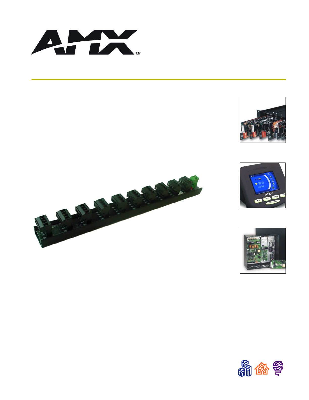
The ABS AXlink Bus Strip (FIG. 1) is a 10-connector AXlink terminal strip designed to simplify
connecting multiple AXlink devices in an AMX Control System.
Use the included double-sided tape to securely affix the unit to the surface.
FIG. 1 ABS Axlink Bus Strip
Specifications
The following table lists the specifications for the ABS Axlink Bus Strip.
Specifications
Power 12 VDC, 7 A max.
Connectors Ten - 4-pin, captive-wire AXlink connectors
One - 2-pin, captive-wire power connector
LED Power indicator (Red)
Enclosure Metal with black matte finish
Dimensions (HWD) 1.14" x 12.00" x 1.27" (2.90 cm x 30.48 cm x 3.23 cm)
Weight 6.70 oz (189.94 g)
Mounting Options 4" double-sided foam tape
Product Information
ABS AXlink Bus Strip
1
Page 6

Product Information
2
ABS AXlink Bus Strip
Page 7
Installation and Wiring
Wiring Guidelines
To determine the maximum distance allowed per gauge, use the following formula and refer to the
table below:
1.5/(Power Consumption x Resistance x 2) = Distance (feet)
Wiring Guidelines
Gauge Resistance
18 AWG .00639
20 AWG .0101
22 AWG .0162
24 AWG .0257
The maximum wiring lengths are based on a minimum of 13.5 volts available to the
ABS.
Installation and Wiring
Preparing/connecting captive wires
1. Strip 0.25 inch of wire insulation off all wires.
2. Insert each wire into the appropriate opening on the connector according to the wiring
diagrams and connector types described in this section.
3. Do not tighten the screws excessively; doing so may strip the threads and damage the
connector.
Wiring
To wire the ABS:
1. Connect wiring from the AXlink devices to connectors 2 through 10 on the ABS (FIG. 2). If
the power LED lights when an AXlink cable is connected to the ABS, it indicates the AXlink
cable has a local power supply. Unless that local supply is intended to power all devices
connected to the ABS, disconnect it and insulate the wire connected to the PWR+ terminal.
All AXlink connectors on the ABS are connected together.
2. Connect the control system AXlink connector 1 on the ABS. As with the other AXlink devices
in the system, connect all four wires to the ABS unless the Central Controller is using a local
power supply.
3. Connect the system power supply to the 2-pin connector on the ABS. The power LED should
ABS AXlink Bus Strip
light, and all AXlink devices with PWR+ connected to the ABS should have power.
3
Page 8

Installation and Wiring
GND
PWR + (RED)
PWR + (RED)
AXP (WHT)
AXP (WHT)
AXM (GRN)
AXM (GRN)
GND - (BLK)
GND - (BLK)
AXlink
Device 9
AXlink
Conn. 10
AXlink
Device 8
AXlink
Conn. 9
AXlink
Device 7
AXlink
Conn. 8
AXlink
Device 6
AXlink
Conn. 7
AXlink
Device 5
AXlink
Conn. 6
AXlink
Device 4
AXlink
Conn. 5
AXlink
Device 3
AXlink
Conn. 4
AXlink
Device 2
AXlink
Conn. 3
AXlink
Device 1
AXlink
Conn. 2
Control
System
AXlink
Conn. 1
Power
Conn.
System
Power
Supply
FIG. 2 ABS wiring diagram
If the AXlink devices have local power supplies, do not connect to the power terminal
of the ABS via the PWR+ (Red).
For additional information about the wiring distances between the ABS and a specific AXlink
device, refer to the appropriate manual.
PWR
4
ABS AXlink Bus Strip
Page 9

Installation and Wiring
ABS AXlink Bus Strip
5
Page 10

AMX reserves the right to alter specifications without notice at any time.
2001 AMX Corporation. All rights reserved. AMX, the AMX logo, the building icon, the home icon, and the light bulb icon are all trademarks of AMX Corporation.
©
brussels • dallas • los angeles • mexico city • philadelphia • shanghai • singapore • tampa • toronto • york
3000 research drive, richardson, TX 75082 USA • 469.624.8000 • 800.222.0193 • fax 469.624.7153 • technical support 800.932.6993
041-004-1561 8/01
AMX reserves the right to alter specifications without notice at any time. *In Canada doing business as Panja Inc.
 Loading...