

Page 1
IP Control Units
8450-03 (3 port version)
8455-03 (1 port version)
8460-03 (3 port version with real-time clock)
8465-03 (1 port version with real-time clock)
8701 control system with IP interface
Installation Guide
Page 2

IP Control Unit Installation Guide V1.1
th
12
February 2008
Contents
1. Introduction to the AMX IP Control Unit......................................................................................................... 2
1.1 General Description ................................................................................................................................. 2
1.2 Electrical Specifications ........................................................................................................................... 2
2. Getting Started............................................................................................................................................... 3
2.1 Physical Connections............................................................................................................................... 3
2.2 Using the loop through facility.................................................................................................................. 4
2.3 Example installation ................................................................................................................................. 4
3 Connecting your IP Control Unit to a network ................................................................................................ 5
3.1 Connecting the Control Unit via a crossover cable.................................................................................. 5
3.2 Connecting the Control Unit to a network with a DHCP server ............................................................... 7
3.3 Connecting the Control Unit using a static IP address (single subnet network)...................................... 8
3.4 Connecting to a network with multiple subnets........................................................................................ 9
Appendix A – Troubleshooting ........................................................................................................................ 10
A.1 I have connected my Control Unit but can’t see it in Site Manager....................................................... 10
A.2 The interface has not picked up the correct IP address via DHCP....................................................... 10
A.3 The ‘link’ light does not light when the network cable is inserted.......................................................... 10
A.4 Why is the ‘link’ light red sometimes? ................................................................................................... 10
Appendix B – Revision History ........................................................................................................................ 11
-1 -
www.amx.com
Page 3
IP Control Unit Installation Guide V1.1
th
12
February 2008
1. Introduction to the IP Control Unit
1.1 General Description
The AMX IP Control Unit allows you to connect your RS232 controlled products to an IP infrastructure and
control them from a single point using the AMX Site Manager software.
There are five variants of the AMX IP Control Unit available, all of which have the following features. See
table 1.1 for a comparison chart of the differences between the variants.
• DHCP or manually configured IP address, subnet mask & default gateway.
• Built in e-mail server so alerts are sent even when Site Manager software is not running.
• 2 available e-mail addresses for multiple alerting.
• Closed loop that can trigger an e-mail alert when the loop is broken, allows hardware to act as a
security measure for expensive audio visual equipment.
• 2 built in timers that can trigger alerts for measuring usage, i.e. e-mail gets sent when the filter on a
projector needs changing.
• Projector lamp expiration alert (uses one of the timers), sends an e-mail to notify that a projector
lamp has passed a preset duration and needs changing (requires Site Manager software to be
running)
• Built in scheduling that operates from the onboard clock allowing events to occur without Site
Manager software.
8450-02 8455-02 8460-02 8465-02 8701-03
Number of RS232 ports 3 1 3 1 2
Loop through port √ √ √ √ x
Power extension port √ x √ x x
Battery backed rtc x x √ √ √
RS232 Interface 13 pin phoenix D9 male 13 pin phoenix D9 male 3 pin phoenix
Closed loop interface 13 pin phoenix 2 pin phoenix 13 pin phoenix 2 pin phoenix 2 pin phoenix
Table 1.1 Comparison of the IP Control Unit variants
1.2 Electrical Specifications
8450-02 8455-02 8460-02 8465-02 8701-03
Supply voltage 12V 12V 12V 12V mains
Supply current (@12V) 250mA 300mA 250mA 300mA X
Power supply included 9V 500mA 9V 500mA 9V 500mA 9V 500mA X
Current drawn with
8416-03 AMX Control
Panel attached to
power loop through.
Operating temperature 0° - 70° F 0° - 70° F 0° - 70° F 0° - 70° F 0° - 70° F
Table 1.2 Electrical specifications of the IP Control Unit variants
375mA
375mA
425mA
425mA
X
-2 -
www.amx.com
Page 4
IP Control Unit Installation Guide V1.1
th
12
February 2008
2. Getting Started
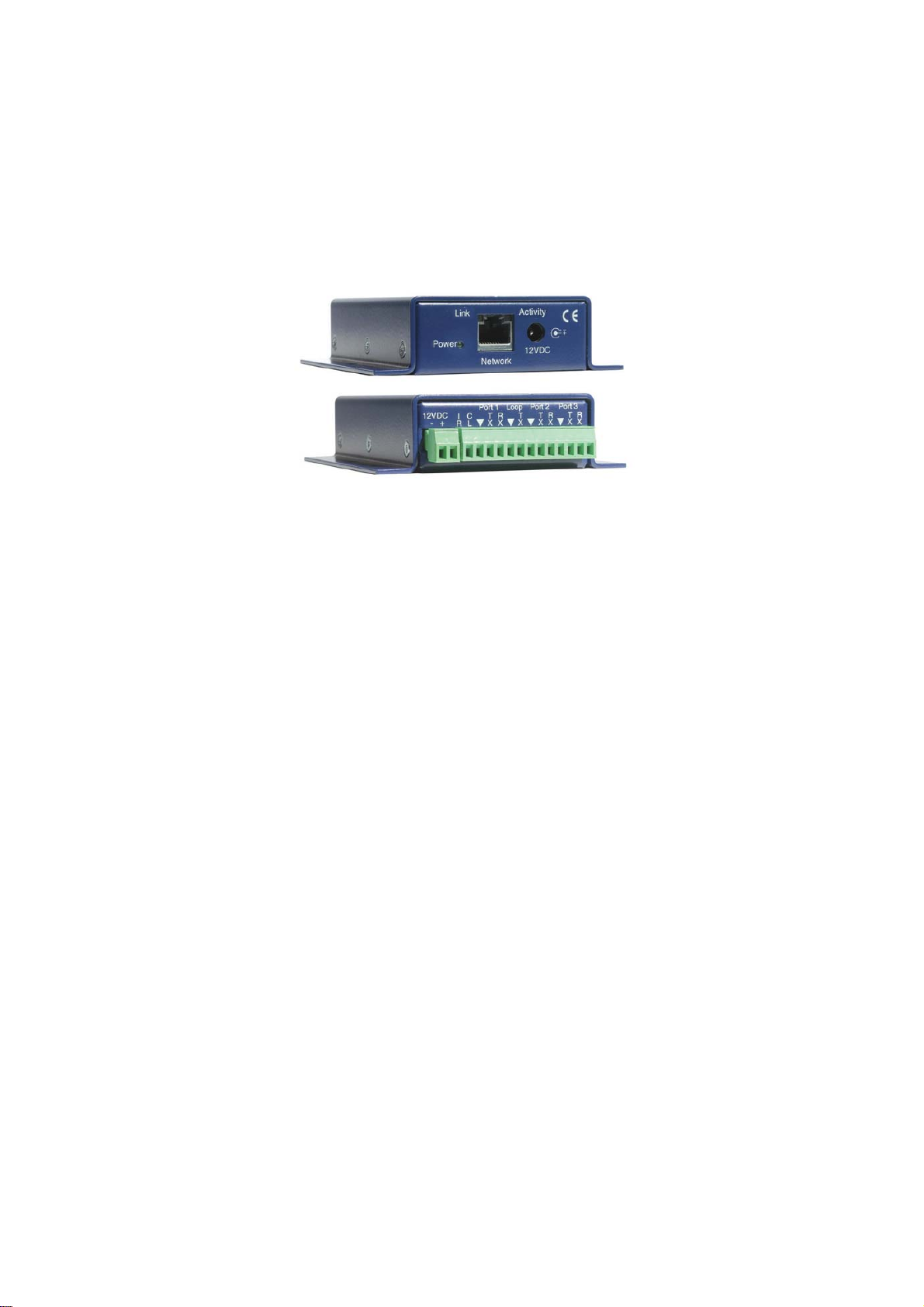
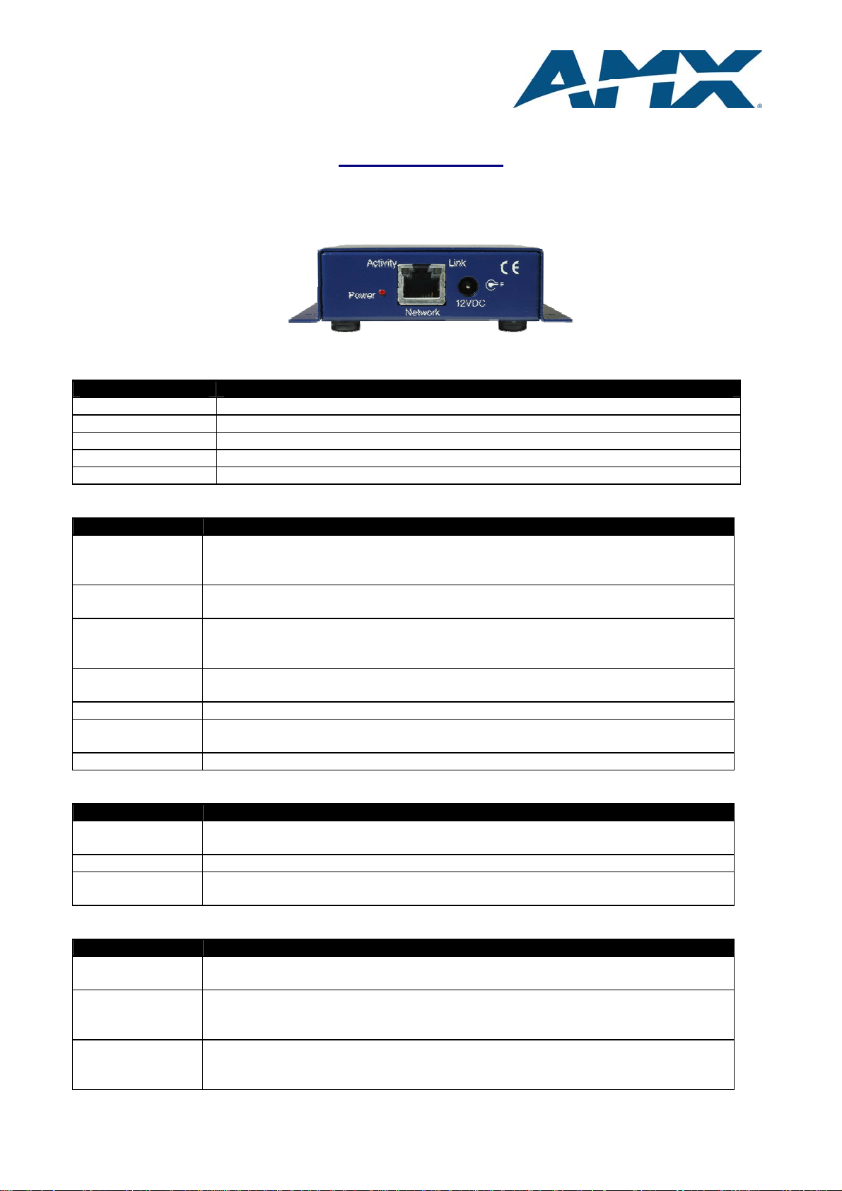
2.1 Physical Connections
Network / Power Connections
Item Description
9VDC Socket for the 2.1mm connector on the power supply
Network Cat 5 socket accepts standard network cable
Power LED Indication that the unit has got power supplied
Link LED Indicator to show that the interface is connected to a network
Activity LED Indicator blinks when data is being sent / received over the network
8450 / 8460 Connections
Item Description
Power 9VDC Can be used as either a loop through power supply if the 9VDC socket is used on
the front of the interface or alternatively can be used to supply the interface with
9V @ 500mA if an alternative power source to the one supplied is required.
CL A connection between this point and ground (▼) signifies a closed loop, once this
connection is broken from ground then an alarm will trigger if required.
Port 1 Bi-directional connection to the first RS232 controlled device. Connect the ‘TX’ to
the ‘RX’ of the device to control and the ‘RX’ to the ‘TX’ of the device to control
with the ground connections commoned together.
Loop This port is input only and any RS232 signals received will be transmitted back out
of Port 2. See section on interface operations.
Port 2 See Port 1 for connection to the second RS232 device.
Loop This port is input only and any RS232 signals received will be transmitted back out
of Port 3. See section on interface operations.
Port 3 See Port 1 for connection to the third RS232 device.
8455 / 8465 Connections
Item Description
CL A connection between these two pins signifies a closed loop, once this connection
is broken an alarm will trigger if required.
Port 1 Connect the D9 cable from this port to the device that you are going to control.
Loop This port is input only and any RS232 signals received will be transmitted back out
of the RS232 Port. See section on interface operations.
8701 Connections
Item Description
CL A connection between this point and ground (▼) signifies a closed loop, once this
connection is broken from ground then an alarm will trigger if required.
P3 Bi-directional connection to the first RS232 controlled device. Connect the ‘TX’ to
the ‘RX’ of the device to control and the ‘RX’ to the ‘TX’ of the device to control
with the ground connections commoned together.
P4 Bi-directional connection to the 2nd RS232 controlled device. Connect the ‘TX’ to
the ‘RX’ of the device to control and the ‘RX’ to the ‘TX’ of the device to control
with the ground connections commoned together
-3 -
www.amx.com
Page 5

IP Control Unit Installation Guide V1.1
th
12
February 2008
2.2 Using the loop through facility
The 8450-02 / 8460-02 have dual loop through facility available allowing the IP Control Unit to sit in the
middle of an existing connection between devices. Any RS232 received on the Loop of port 2 is sent straight
out of the TX of port 2 and likewise anything received on the loop of port 3 gets sent out of port 3.
2.3 Example installation
Figure 2.3 shows and example installation correctly wired to maximise the potential of the IP Control Unit.
You will see that the way the setup is connected, the control panel makes use of both loop through paths in
order to allow local control of the projector and switcher with the IP Control Unit still having full access to the
devices for remote control.
Figure 2.3 Example installation correctly wired to maximise system pot ential
-4 -
www.amx.com
Page 6

IP Control Unit Installation Guide V1.1
th
12
February 2008
Connecting the IP Control Unit to a network
When you first receive your IP Control Unit, it is configured to obtain it’s network IP address, subnet mask
and default gateway via DHCP. Follow the procedures listed below that best describe the situation that you
are installing the Control Units into.
3.1 Connecting the Control Unit via a crossover cable
Before connecting the IP Control Unit to the computer check that the PC’s network connection is set to
‘Obtain An IP Address Automatically’.
Click - Start
Click - Control Panel
Double Click - Network Connections
Select - Local Area Connection
Right Click and Select - Properties.
Click - Internet Protocol (TCP/IP)
Select - Properties
Select the first option - Obtain An IP Address Automatically
If there is a tab at the top saying ‘Alternate Configuration’ select it and select the option ‘Automatic
Private IP Address’.
Now connect the IP Control Unit to the computer using a crossover cable and you will see this icon
appear in the task bar. When the yellow dot stops moving back and forth or the icon disappears then the
computer has finished initialising and it will have assigned itself an Automatic Private Address (169.254.x.x),
please note this may take several minutes. As there is no DHCP server present in the connection, the IP
Control Unit will also have assigned itself a 169.254.x.x address.
-5 -
www.amx.com
Page 7

IP Control Unit Installation Guide V1.1
th
12
February 2008
Now start up Site Manager, and proceed as follows:
From the Site Details within the Site List
Click - Add Building
Click - Add Room
From IP Device with the Site List
Click - Add Interface
The IP Control Unit should be present in the list.
Double Click the Interface
Click - Done
The IP Control Unit is now ready for use symbolised by the green ticks.
For more information on using the Site Manager software please refer to the instruction manual.
-6 -
www.amx.com
Page 8

IP Control Unit Installation Guide V1.1
th
12
February 2008
3.2 Connecting the Control Unit to a network with a DHCP server (single subnet network)
If the network has a DHCP server installed then it may be necessary to register the MAC Hardware Address
of the IP Control Unit (supplied with the products) with the Network Administrator. This means that even
though there is a DHCP server to assign the network address, some networks do not allow ‘unknown’
devices to connect to them and so the DHCP server will not give them an address. This can cause problems
as the IP Control Units could assign themselves an address which would then be in conflict with other
devices. It is essential that this is resolved before installing the interfaces.
The IP Control Unit is delivered pre-configured to acquire its network information from a DHCP server.
Connect the interface to a suitable network port using a standard network patch cable and then apply power.
After a few seconds the unit will have configured itself and be ready to use. Open the Site Manager software
and:
Click – Add from the IP Device menu at the bottom of the Site List
The IP device will be present in the list.
Double Click the Control Unit
Click - Done
The IP Control Unit is now ready for use symbolised by the green ticks.
-7 -
www.amx.com
Page 9

IP Control Unit Installation Guide V1.1
th
12
February 2008
3.3 Connecting the Control Unit using a static IP address (single subnet network)
There are two methods for achieving this:
1) Plug the IP Control Unit into an available network socket using a network patch cable, apply
power and after a few seconds the interface will appear in the Site Manager add device list with
‘no route available’.
A message will also appear indicating a device on the network that is not compatible with your
current network settings.
Selecting the device
Click - Edit or Double Click on the device
When asked if you wish to perform a DHCP reset on the device,
Click – No
Enter - the desired IP address.
After a few seconds the IP Control Unit will re-appear in the window with the new IP address and
can be added to your Site List. If you use this method, you must go into the properties of the
device afterwards and select properties, re-type the IP address and click ‘Update Settings’.
2) The second method, is to connect the device using a crossover cable (see instructions 3.1) so
that the PC and the IP Control Unit are both on the same 169.254.x.x network. Then add the
device, select it and change it’s properties to the correct values and click ‘Update Settings’.
The second method is probably the easier of the two as the address only needs to be entered
once hence eliminating the possibility of conflicting settings being entered. Although the first can
be performed over the network.
-8 -
www.amx.com
Page 10

IP Control Unit Installation Guide V1.1
th
12
February 2008
3.4 Connecting to a network with multiple subnets
Before proceeding with the installation of devices over subnets it imperative to inform the network
administrator. If there is a DHCP server then the devices MAC address will need to be registered so that the
DHCP server knows which subnet to assign its address to, if not then the administrator will assign the device
a static IP address in which case the default gateway and subnet mask will also need to be known.
If a DHCP server is in use the unit will automatically configure its IP address, subnet mask and default
gateway. Unless the DHCP server gives the IP Control Unit a fixed IP address there is the possibility of it
being given a different IP Address after a power or network failure and the Site Manager software will show
the IP Control Unit as being offline because the properties are now different. It is recommended that if a
DHCP server is used then it assigns the IP Control Unit a fixed IP address.
If you prefer to manually assign a static IP address then please refer to section 3.1 before continuing.
To add the Control Unit into your site list,
Click - Add Device
Click – Manual and enter the IP address and MAC address of the IP Control Unit
Click – Add
The software will then attempt to connect to the Control Unit and assuming that all the network routes are
correct a green tick will appear besides the unit.
-9 -
www.amx.com
Page 11

IP Control Unit Installation Guide V1.1
th
12
February 2008
Appendix A – Troubleshooting
A.1 I have connected my Control Unit but can’t see it in Site Manager
• Check that the link light is lit, if not then check that the network cables are securely located at each
end. Try replacing the network cable.
• If you are connecting directly, have you used a crossover cable or if connecting to a switch, have you
used a crossover cable when a normal patch cable is required.
• Do you have multiple network adapters in your PC, try disabling all other network adapters so that
the one connected to the IP interface is the only one available.
A.2 The Control Unit has not picked up the correct IP address via DHCP
• The DHCP request has failed, reset the power to the interface and try again.
• Check with the network administrator as to whether or not the MAC address of the interface needs to
be registered with the DHCP server before it will assign it an address.
A.3 The ‘link’ light does not light when the network cable is inserted
• Try using a different cable, there may be a broken wire in it.
• Check the network port by plugging in a PC to make sure the network port works and is patched
through correctly.
• Is the power light illuminated on the Control Unit? If it is not then try replacing the power supply.
A.4 Why is the ‘link’ light red sometimes?
• The link light shows red during the interfaces initial setup whilst it is auto negotiating the connection
speed available to the network.
• The link light’s colour signifies the connection speed, a 100Mbs full duplex connection will show as
green whilst a 10Mbs connection or a half duplex connection will show as red.
- 10 -
www.amx.com
Page 12

IP Control Unit Installation Guide V1.1
th
12
February 2008
Appendix B – Revision History
Date Revision Notes
20.06.05 1.0 First release
12.02.08 2.0 Updated for V3 interfaces
- 11 -
www.amx.com
 Loading...