

Page 1

AMX™ 86 User's Guide
First Printing: November 1, 1990
Last Printing: March 1, 2005
®
Copyright © 1990 - 2005
KADAK Products Ltd.
206 - 1847 West Broadway Avenue
Vancouver, BC, Canada, V6J 1Y5
Phone: (604) 734-2796
Fax: (604) 734-8114
Page 2

Page 3

TECHNICAL SUPPORT
KADAK Products Ltd. is committed to technical support for its software products. Our
programs are designed to be easily incorporated in your systems and every effort has
been made to eliminate errors.
Engineering Change Notices (ECNs) are provided periodically to repair faults or to
improve performance. You will automatically receive these updates during the product's
initial support period. For technical support beyond the initial period, you must purchase
a Technical Support Subscription. Contact KADAK for details. Please keep us inform ed
of the primary user in your company to whom update notices and other pertinent
information should be directed.
Should you require direct technical assistance in your use of this KADAK software
product, engineering support is available by telephone, fax or e-mail. KADAK reserves
the right to charge for technical support services which it deems to be beyond the normal
scope of technical support.
We would be pleased to receive your comments and suggestions concerning this produ ct
and its documentation. Your feedback helps in the continuing product evolution.
AMX 86 User's Guide
KADAK Products Ltd.
206 - 1847 West Broadway Avenue
Vancouver, BC, Canada, V6J 1Y5
Phone: (604) 734-2796
Fax: (604) 734-8114
e-mail: amxtech@kadak.com
KADAK
i
Page 4

Copyright © 1990-2005 by KADAK Products Ltd.
All rights reserved.
No part of this publication may be reproduced, transmitted, transcribed,
stored in a retrieval system, or translated into any language or computer
language, in any form or by any means, electronic, mechanical,
magnetic, optical, chemical, manual or otherwise, without the prior
written permission of KADAK Products Ltd., Vancouver, B.C., CANADA.
DISCLAIMER
KADAK Products Ltd. makes no representations or warranties with
respect to the contents hereof and specifically disclaims any implied
warranties of merchantability and fitness for any particular purpose.
Further, KADAK Products Ltd. reserves the right to revise this
publication and to make changes from time to time in the content
hereof without obligation of KADAK Products Ltd. to notify any
person of such revision or changes.
TRADEMARKS
AMX in the stylized form and KwikNet are registered trademarks of KADAK Products Ltd.
AMX, AMX/FS, InSight,
Microsoft, MS-DOS and Windows are registered trademarks of Microsoft Corporation.
All other trademarked names are the property of their respective owners.
ii
KwikLook and KwikPeg are trademarks of KADAK Products Ltd.
KADAK
AMX 86 User's Guide
Page 5

Section 1: System Description
1. AMX Overview 1
1.1 Introduction ........................................................................................ 1
1.2 Glossary ............................................................................................. 3
1.3 AMX Nomenclature ........................................................................... 7
2. General AMX Operation 9
2.1 Introduction to Multitasking ............................................................... 9
2.2 AMX Operation ................................................................................. 11
2.3 AMX Managers .................................................................................. 17
2.4 Starting AMX ..................................................................................... 20
3. Application Tasks 25
3.1 Task Creation ..................................................................................... 25
3.2 Task States ......................................................................................... 27
3.3 Starting a Task .................................................................................... 29
3.4 Task Priority ....................................................................................... 30
3.5 Task Execution ................................................................................... 31
3.6 Task and Event Synchronization ........................................................ 32
3.7 Task Timing ....................................................................................... 34
3.8 Ending a Task ..................................................................................... 35
3.9 Message Passing ................................................................................. 36
3.10 Restart Procedures ............................................................................ 42
3.11 Exit Procedures ................................................................................ 44
3.12 Task Enhancements .......................................................................... 46
AMX 86 USER'S GUIDE
Table of Contents
Page
AMX 86 User's Guide
4. Interrupt Service Procedures 49
4.1 The Processor Interrupt Facility ......................................................... 49
4.2 ISPs for External Interrupts ................................................................ 51
4.3 Nested Interrupts ................................................................................ 56
4.4 ISP/Task Communication .................................................................. 57
4.5 Task Error Traps ................................................................................ 60
4.6 Non-Maskable Interrupt ..................................................................... 64
4.7 Special Interrupts ............................................................................... 65
4.8 Vector Table Initialization ................................................................. 68
5. AMX Timing Control 69
5.1 Introduction to Timing Facilities ........................................................ 69
5.2 AMX Clock Handler and Kernel Task ............................................... 71
5.3 Interval Timers and Timer Procedures ............................................... 75
5.4 Task Time Slicing .............................................................................. 79
5.5 Time/Date Manager ............................................................................ 82
KADAK
iii
Page 6

AMX 86 USER'S GUIDE
Table of Contents (Cont'd.)
Section 1: System Description (Cont'd.)
6. AMX Semaphore Manager 91
6.1 Introduction ........................................................................................ 91
6.2 Semaphore Use ................................................................................... 93
6.3 Semaphore Applications .................................................................... 97
7. AMX Event Manager 103
7.1 Introduction ........................................................................................ 103
7.2 Event Synchronization ....................................................................... 105
7.3 Event Flag Application ....................................................................... 107
8. AMX Message Exchange Manager 111
8.1 Introduction ........................................................................................ 111
8.2 Message Exchange Use ...................................................................... 113
8.3 Message Exchange Application ......................................................... 115
Page
9. AMX Buffer Manager 119
9.1 Introduction ........................................................................................ 119
9.2 Buffer Pool Use .................................................................................. 120
9.3 Buffer Applications ............................................................................ 122
9.4 Buffer Manager Caveats ..................................................................... 124
10. AMX Memory Manager 125
10.1 Introduction ...................................................................................... 125
10.2 Nomenclature ................................................................................... 127
10.3 Memory Allocation .......................................................................... 128
10.4 Private Memory Allocation .............................................................. 130
10.5 Memory Assignment ........................................................................ 131
10.6 Memory Assignment Procedure ....................................................... 132
11. AMX Circular List Manager 135
11.1 Circular Lists .................................................................................... 135
11.2 Circular List Use .............................................................................. 136
11.3 Circular List Structure ...................................................................... 137
iv
KADAK
AMX 86 User's Guide
Page 7

AMX 86 USER'S GUIDE
Table of Contents (Cont'd.)
Section 1: System Description (Cont'd.)
12. AMX Linked List Manager 139
12.1 Introduction ...................................................................................... 139
12.2 Linked Lists ...................................................................................... 140
12.3 Linked List Use ................................................................................ 142
13. Advanced Topics 147
13.1 Fatal Exit .......................................................................................... 147
13.2 User Error Procedure ........................................................................ 150
13.3 Task Scheduling Hooks .................................................................... 152
13.4 Abnormal Task Termination ............................................................ 153
13.5 Task Suspend/Resume ...................................................................... 158
13.6 Breakpoint Manager ......................................................................... 159
Section 2: System Construction
Page
14. AMX System Configuration 163
14.1 System Configuration Module ......................................................... 163
14.2 System Configuration Builder .......................................................... 164
14.3 Using the Builder ............................................................................. 166
14.4 System Parameter Definition ............................................................ 170
14.5 AMX Object Allocation ................................................................... 173
14.6 Restart/Exit Procedure Definition .................................................... 176
14.7 Task Definition ................................................................................. 178
14.8 Timer Definition ............................................................................... 181
14.9 Semaphore Definition ...................................................................... 183
14.10 Event Group Definition .................................................................. 185
14.11 Message Exchange Definition ........................................................ 187
14.12 Buffer Pool Definition .................................................................... 189
14.13 Breakpoint Manager Definition ...................................................... 191
Section 3: Programming Guide
15. AMX Service Procedures 193
15.1 Introduction ...................................................................................... 193
15.2 Summary of Services ....................................................................... 194
AMX 86 User's Guide
16. AMX 86 Procedures 201
16.1 Introduction ...................................................................................... 201
Alphabetic List of Procedures .......................................................... 205
KADAK
v
Page 8

Appendices
A. AMX 86 Reserved Words 347
B. AMX 86 Error Codes 349
C. Configuration Generator Specifications 353
D. AMX 86 Structure and Constant Definitions 365
E. AMX 86 Assembler Interface 381
AMX 86 USER'S GUIDE
Table of Contents (Cont'd.)
Page
C.1 Introduction ....................................................................................... 353
C.2 User Parameter File Specification ..................................................... 354
C.3 System Configuration Template ........................................................ 359
C.4 Porting the Configuration Generator ................................................. 362
D.1 AMX C Structures and Constants ..................................................... 365
D.2 AMX Assembler Structures and Constants ....................................... 373
Index Index-1
AMX 86 USER'S GUIDE
Table of Figures
Page
Section 1: System Description
Figure 2.2-1 AMX General Operation ..................................................... 12
Figure 3.2-1 AMX Task State Diagram ................................................... 28
Figure 3.9-1 Message Transmission ......................................................... 38
Figure 3.9-2 Message Reception .............................................................. 39
Figure 5.4-1 Simple Time Slicing ............................................................ 80
Figure 5.4-2 Interrupted Time Slicing ...................................................... 80
Figure 5.5-1 Time/Date Format Specification Parameter ........................ 89
Figure 12.2-1 Doubly Linked Lists ........................................................... 141
Section 2: System Construction
Figure 14.2-1 AMX Configuration Building Process .............................. 165
Figure 14.3-1 Configuration Manager Screen Layout .............................. 167
Appendices
Figure C.2-1 User Parameter File ............................................................. 354
vi
KADAK
AMX 86 User's Guide
Page 9

1. AMX Overview
1.1 Introduction
The AMX™ Multitasking Executive provides a simple solution to the complexity of realtime multitasking. AMX supervises the orderly execution of a set of application program
modules called tasks. AMX allows the system designer to concentrate on the application
without becoming overly concerned about the multitasking aspects of the solution.
AMX is based on concepts proven over the past thirty years in minicomputer and
microprocessor applications in process control environments. AMX simplifies real-time
software implementation by providing the system designer with a well-defined set of
rules.
AMX operates in real mode on any Intel
including the 8086/8088, 80186/188, 80286, Intel386
also be used on the VAutomation 24-bit Turbo86 processor family. Unless otherwise
specified, references in this manual to 8086 infer all of the other processors as well.
AMX gives the system designer complete flexibility and control over the microcomputer
configuration employed. A real-time clock must be provided in the configuration if
AMX timing facilities are to be employed.
AMX provides a wide variety of services from which the real-time system designer can
choose. Many of the services are optional and, if not used, will not even be present in
your AMX system. The AMX managers are all optional.
®
8086 compatible microprocessor system
™
, Intel486™ and Pentium™. It can
The purpose of this manual is to provide the system designer and applications
programmer with the information required to properly configure and implement an
AMX-based real-time operating system. It is assumed that you are familiar with the
architecture of the processor on which you will be using AMX. It is further assumed that
you are familiar with the rudiments of microprocessor programming including the
concepts of code, data and stack separation.
For historical reasons, AMX 86 is coded in assembly language. The result is a fast,
compact, reliable implementation whose code has remained invariant throughout the
lifetime of this very stable product. AMX is provided in source format to ensure that
regardless of your development environment, your ability to use and support AMX is
uninhibited.
The C programming language, commonly used in real-time s ystems, is used throughout
this manual to illustrate the features of AMX.
AMX Overview
KADAK
1
Page 10

Section Summary
This manual is divided into three sections. Each section is divided into chapters.
Section 1 of this manual describes the AMX Multitasking System and how it is used.
Separate chapters are provided for each of the AMX managers.
Section 2 describes the AMX System Configuration Builder and the manner in which it is
used to create your AMX System Configuration Module.
Section 3 is the application programming guide. It provides detailed descriptions of all of
the AMX service procedures which are available in the AMX Library.
AMX Guides
This manual describes the use of AMX 86 for all target processors on which it can be
used. Target specific requirements or programming considerations are provided only
when necessary to clarify proper operation on a particular processor.
This manual describes the use of AMX in a tool set independent fashion. References to
specific assemblers, compilers, librarians, linkers, locators and debuggers a re purposely
omitted. The AMX 86 Tool Guide provides guidance for the proper use of AMX with
each toolset with which AMX has been tested.
Guidelines for the proper use of AMX when coding in C are provided in the separate
AMX 86 C Programming Guide. This guide includes useful debugging tips as well as a
description of the AMX Sample Program provided with AMX.
The AMX 86 T iming Guide discusses general timing issues related to the use of AMX.
Timing metrics generated for specific boards and software development toolsets are also
provided. These timing figures can be used as guidelines to expected AMX performance,
but are not to be construed as product specifications. The AMX Timing Guide is
provided as an appendix in the AMX 86 Tool Guide.
Note
The AMX 86 PC Supervisor is delivered with AMX for use
in the development of applications which must run on PCs
with access to PC peripherals and DOS.
The AMX 86 PC Supervisor Reference Manual is provided
in its own section of this manual.
2
KADAK
AMX Overview
Page 11

1.2 Glossar y
Buffer Pool A collection of data buffers whose use is controlled by the AMX
Buffer Manager.
Buffer Pool Id The handle assigned to a buffer pool by AMX for use as a unique
buffer pool identifier.
Circular List An application data structure used to maintain a list of 1, 2 or 4
byte elements with the ability to add and remove elements at both
the top (head) and bottom (tail) of the list.
Clock Handler The name given to the AMX procedure which is called by the ISP
root which services the hardware clock interrupt.
Clock Tick The interrupt generated by a hardware clock.
Conforming ISP An Interrupt Service Procedure consisting of an ISP root which
calls an Interrupt Handler which has the right to make calls to a
subset of the AMX service procedures.
Counting Semaphore
A particular type of AMX semaphore used for event signalling or
for controlling access by tasks to multiple resources.
Envelope The private data storage element used b y AMX to pass a m essage
to a task mailbox or message exchange.
Error Code A series of signed integers used by AMX to indicate error or
warning conditions detected by AMX service procedures.
Event Group A set of 16 events whose access and signalling is controlled by the
AMX Event Manager.
Event Group Id The handle assigned to an event group by AMX for use as a unique
event group identifier.
Exit Procedure An AMX or application procedure executed by AMX during the
exit phase when an AMX system is shut down.
Fatal Error A condition detected by AMX which is considered so abnormal
that to proceed might risk catastrophic consequences. Examples
include, but are not limited to, insufficient memory in the AMX
Data Segment or division by zero in an ISP.
FIFO First in, first out. Usually used to refer to the ordering of elements
in a queue, circular list or linked list.
Group Id See Event Group Id.
Handle An identifier assigned by AMX for use by your application to
AMX Overview
reference a private AMX system data item.
KADAK
3
Page 12

Interrupt Handler An application procedure called from an ISP root to service an
interrupting device.
Interrupt Service Procedure (ISP)
An AMX or application procedure which is executed in response
to an external device interrupt request.
ISP See Interrupt Service Procedure
ISP root The ISP code fragment (produced by AMX function ajispm())
which informs AMX that an interrupt has occurred and calls an
application Interrupt Handler.
Kernel Task The private AMX task which is responsible for all timing control
and event sequencing in an AMX system.
Linked List An application data structure used to maintain a doubly-linked list
of arbitrary application data elements with the ability to add and
remove elements at head, tail or specified positions in the list.
List Element An 8-bit, 16-bit or 32-bit value which can be added to or removed
from a circular list.
Mailbox An AMX data structure consisting of a single message queue.
Mailboxes allow the interchange of messages between two or more
cooperating components (tasks, ISPs, etc.) of an AMX system.
Each task or message exchange can have up to four mailboxes.
Memory Block A portion of a memory section that has been allocated for use by
one or more tasks.
Memory Handle The handle assigned to a private memory section by AMX for use
as a unique memory section identifier.
Memory Section A contiguous region of memory assigned to the AMX Memory
Manager for allocation to application tasks.
Message Application information passed by AMX in an envelope to a task
mailbox or message exchange.
Message Exchange An AMX data structure that consists of four message queues, each
for messages of a different priority. The message exchanges allow
the interchange and prioritization of messages between two or
more cooperating components (tasks, ISPs, etc.) of an AMX
system.
Message Exchange Id
The handle assigned to a message exchan ge by AMX for use as a
unique message exchange identifier.
4
KADAK
AMX Overview
Page 13

Message Queue An AMX data structure used to manage messages sent to a task
mailbox or message exchange. A separate message queue is
provided for each of the four message priorities which a task or
message exchange can support.
Message Priority Identifies which of a task's or message exchange's four message
queues is to receive the AMX message.
Nonconforming ISP An Interrupt Service Procedure which bypasses AMX completely
and hence cannot use any AMX service procedures.
RAM Alterable memory used for data storage and stacks.
Resource Semaphore
A particular type of AMX semaphore used to provide access to an
entity such as a math coprocessor, disk file or non-reentrant library
whose ownership is to be controlled by the AMX Semaphore
Manager.
Restart Procedure An AMX or application procedure executed by AMX during the
initialization phase when an AMX system is started.
ROM Read only memory of all types including PROMs, EPROMs and
EAROMs.
Segment An area of memory in which AMX code or data is stored.
Segments are sometimes called sections or regions according to the
nomenclature adopted for a particular processor.
Semaphore An AMX data structure which can be used by the AMX
Semaphore Manager to provide an event signalling mechanism or
mutually exclusive access by tasks to specific user facilities.
Semaphore Id The handle assigned to a semaphore by AMX for use as a unique
semaphore identifier.
Slice Interval The interval of time allocated to a task which is time sliced.
Slot One of n locations used to store list elements in a circular list.
System Configuration Module
A software module, produced by the AMX S ystem Configuration
Builder, which defines the characteristics of a particular AMX
application.
System Tick A multiple of the hardware clock tick from which the fundament al
AMX unit of time is derived. All time intervals in an AMX system
are measured in multiples of the system tick.
Tag A 4-character name that can b e assigned to an y AMX system dat a
structure when it is created. A tag can be used to find the identifier
of a task, timer, semaphore, event group, message exchange or
buffer pool with a particular name.
AMX Overview
KADAK
5
Page 14

Task An application procedure which is executed by AMX in a way
which makes it look as though all such procedures are ex ecuting at
once.
Task Control Block (TCB)
A private data structure maintained by AMX for each task in the
system.
Task Id The handle assigned to a task by AMX for use as a unique task
identifier.
Task Priority The priority at which a task executes. Tasks which have the same
task priority are actually ordered in priority according to the order
in which the tasks were created.
Task Signal A set of 15 user-defined event signals associated wi th ea ch task for
task synchronization use.
TCB See Task Control Block
Time Slice The process by which AMX allows tasks having the same priority
to share the use of the processor in a round robin fashion.
Timer A facility provided by AMX to permit precise interval
measurement in AMX applications.
Timer Id The handle assigned to a timer by AMX for use as a unique timer
Identifier.
Timer Procedure An application procedure which is executed by the AMX Kernel
Task whenever the corresponding timer interval expires.
6
KADAK
AMX Overview
Page 15

1.3 AMX Nomenclature
The following nomenclature has been adopted throughout the AMX User's Guide.
Processor registers are referenced as follows:
8-Bit Registers AH, AL, BH, BL, CH, CL, DH, DL
16-Bit Registers AX, BX, CX, DX, SP, BP, SI, DI
Instruction Pointer IP
Flags (Condition Code) CC
Segment Registers CS, DS, SS, ES
The processor flags (condition code) are referenced using the mnemonics employed in
software branches as follows:
Zero Z
Non-zero NZ
Carry C
No Carry NC
Positive (no sign) NS
Minus (sign) S
Interrupt flag IF
Direction flag UP if forward; DN if backward
Numbers used in this manual are decimal unless otherwise indicated. Hexadecimal
numbers are indicated as 0xABCD in C code or 0ABCDH in assembly language code.
The terminology A(Table XYZ) is used to define add resses. It is r ead as "t he address of
Table XYZ".
Addresses are written as segment:offset. For example ES:BX is the address with segment
determined by extended register ES and offset determined by base register BX.
Read/write memory is referred to as RAM. Read only memory (non-volatile storage) is
referred to as ROM.
AMX symbol names are identified as follows:
ajxxxx AMX procedure called from C
AAXXXX AMX procedure called from assembler
AMXXXX Private AMX procedures, structures and constants
AERXXX AMX Error Code XXX
AA831xxx.xxx AMX kernel filenames
AJ831xxx.xxx AMX C Interface filenames
AMxxxxxx.xxx AMX reserved filenames
AA832xxx.xxx AMX PC Supervisor filenames
Throughout this manual examples are provided in C and assembly language. In general,
code examples in C are presented in lower case. Code examples in assembler are in
upper case. File names are shown in upper case. C code assumes that an int is 16 bits as
is common for most C compilers for the 8086 family.
AMX Overview
KADAK
7
Page 16

This page left blank intentionally.
8
KADAK
AMX Overview
Page 17

2. General AMX Operation
2.1 Introduction to Multitasking
A real-time system is characterized by the need to respond rapidly to events occurring
asynchronously in time. A multitasking system is one in which a number of activities or
processes must be performed simultaneously without interference with each other. A
system in which several activities must operate simultaneously with time-critical
precision is called a real-time multitasking system.
The AMX Multitasking Executive provides a simple solution to the
complexity of real-
time multitasking. AMX supervises the orderly execution of a set of application program
modules called tasks. Each task solves a particular problem and provides a specific
functional capability within the system.
As we all know, the microprocessor can only do one thing at a time. Fortunatel y, it does
all things very quickly. However, to get the effect that all activities are occurring
simultaneously, it is necessary to rapidly switch back and forth from one process to
another in a well controlled fashion. It is AMX which organizes and controls the use of
the microprocessor to achieve this apparent concurrent execution of tasks.
Each task solves a particular problem or provides a specific functional capability within
the system. Each task executes independent of other tasks. Facilities are provided,
however, to permit tasks to co-operate to achieve a common goal. This process in which
more than one task is allowed to share the use of a single processor is called multitasking.
The software program which makes it possible is AMX.
What a task does is completely application dependent. In fact, the most difficult aspect
of system design is to logically break the problem into a set of tasks which, if
implemented, will achieve the desired goal. The following example is presented to
illustrate one way in which a simple real-time alarm logging system can be implemented.
Example
Assume that it is necessary to periodically scan a set of digital alarm inputs. When any
alarm is detected, a message is to be logged on a printer. The message is to include a
description of the alarm and the time of day at which it occurred.
Careful examination of this problem indicates that in fact it is three problems. First, a set
of digital inputs must be scanned for the detection of alarms. Second, a message must be
printed. Finally, the time of day must be maintained for inclusion in the message.
Three problems usually result in three tasks. Our example is no exception. A time of day
task is required to maintain the date and time within the system. The task must be
executed once each second if time is to be maintained to the nearest second. We will
ignore the requirement to somehow set the proper time and date. (Isn't that another task?)
General AMX Operation
KADAK
9
Page 18

Alarm scanning will likely be hardware dependent. We will simplify matters by
assuming that a scanning task must examine all digital inputs every 100 ms. The task
must be capable of detecting alarm changes in the digital inputs. When an alarm is
detected, the scanning task must initiate the logging of a message.
However, the scanning task is not allowed the luxury of waiting until the message is
printed. It must continue scanning for additional alarms at the same 100 ms rate. The
scanning task must, therefore, send to the message task parameters identifying the alarm
which has occurred and the time at which it was detected.
The message task is very simple to describe. It receives parameters identifying the time
at which a particular alarm occurred. The task must output to a printer a message
describing the alarm.
The foregoing example, although very simple, illustrates many of the features of a realtime multitasking system. At first, the implementation of the required set of tasks may be
difficult to envision. Two of the tasks must operate periodically at different intervals.
The third task, printing, is such a slow process that the other two tasks must be allowed to
execute with higher priority. Moreover, provision must be made to allow the alarm
parameters to continue piling up on the message task when alarms are occurring at a rate
faster than can be printed. (What would we do if we had to print high priority alarms first
and delay the printing of lower priority alarms?)
The implementation of the proposed solution is greatly simplified by AMX. AMX will
supervise the execution of the three tasks in the defined priority order. Timing facilities
are provided by AMX with a resolution governed by the hardware clock. AMX supports
message passing between tasks. AMX allows these messages to pile up at the destination
task at any of four priority levels because automatic message queuing with priority
sorting is an inherent feature of AMX.
This introduction to multitasking is not exhaustive. The intent is to remove some of the
mystery from the multitasking concept. The above example is intended to inspire
confidence in your ability to understand AMX and use it to solve real-time problems.
10
KADAK
General AMX Operation
Page 19

2.2 AMX Operation
AMX Startup
Each AMX-based system consists of the AMX executive program and a set of
application tasks and interrupt service procedures. This collection of programs resident
in the memory of the microprocessor configuration represents the entire operating
system.
The manner in which the operating system begins execution is application dependent. In
ROM-based systems, automatic hardware vectoring to the program start address is often
implemented. In RAM-based systems, the program is first loaded from some storage
medium (ROM, hard disk, diskette, etc.) or downloaded from one processor to another.
Once the program is loaded, it is started at its start address by the loader.
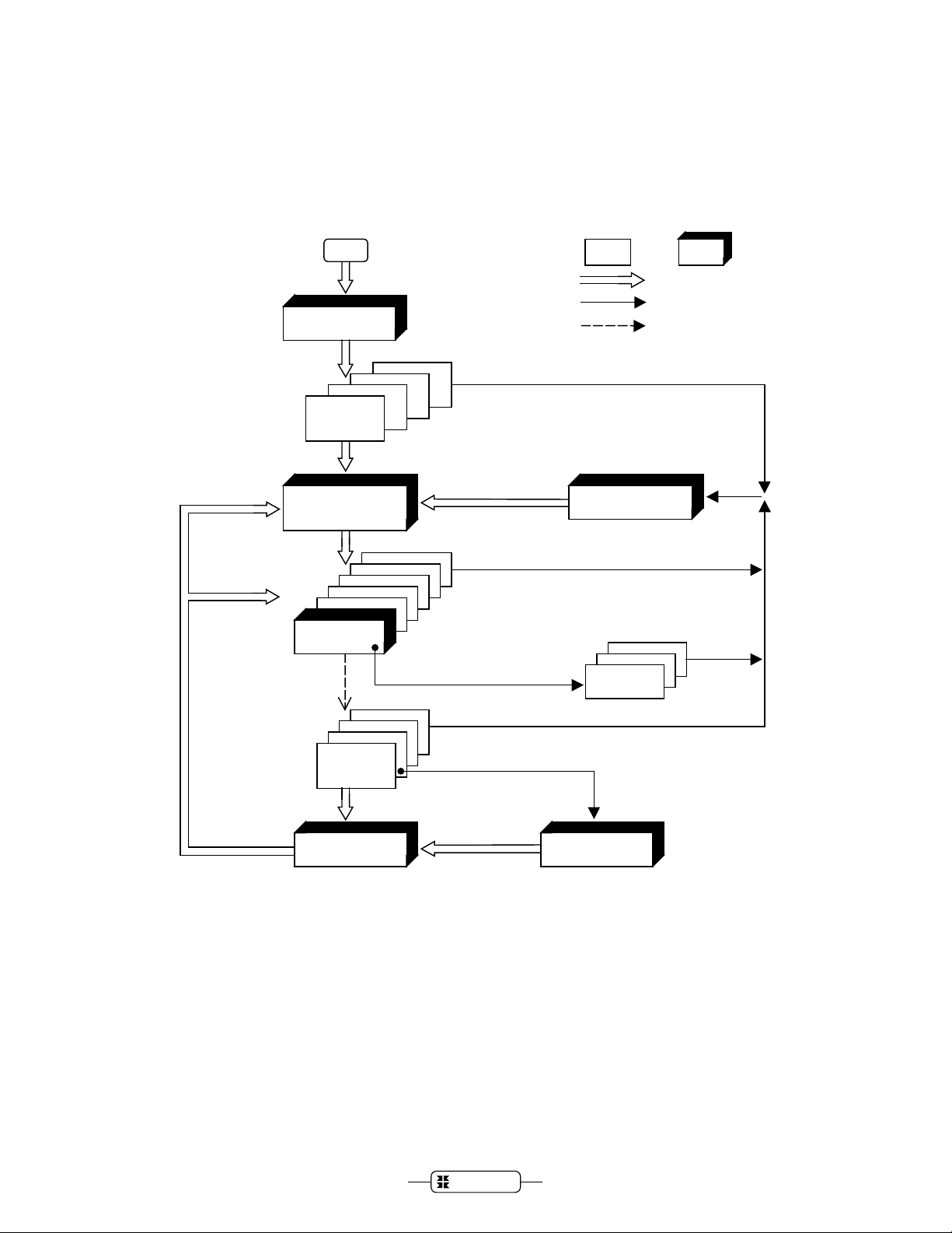
Figure 2.2-1 illustrates the general operation of an AMX system. Execution be gins in the
user domain providing the opportunity for hardware specific and application dependent
setup prior to the initialization of the AMX system. For example, hardware interfaces
may require custom configuring. In some systems, it might be desirable to perform a
memory integrity check before system startup is permitted.
Once all custom initialization has been performed, the program calls the AMX entry
procedure ajentr. Operating characteristics are defined in an AMX System
Configuration Module. It is possible to predefine specific tasks and timers which will be
automatically created by AMX during its initialization phase. AMX initializes itself and
places all application tasks and timers into an idle state.
Once AMX has initialized all of its internal variables and structures, it executes a
sequence of user provided Restart Procedures. These procedures can invoke AMX
services to start tasks and initialize interval timers.
General AMX Operation
KADAK
11
Page 20
Start
k
Initialization
Restart
Procedure
User AMX
Control Flow
Functi on calls
Interrupts
Task S cheduler
Task A
Kernel Task
Clock
Interrupt
Service
Procedure
Interrupt
Supervisor
Task N
Cloc
Handler
Services
Timer
Procedure
Figure 2.2-1 AMX General Operation
12
KADAK
General AMX Operation
Page 21

The Task Scheduler
Following system initialization, AMX proceeds to its Task Scheduler. The Task
Scheduler searches its list of available tasks to determine the highest priority task capable
of execution. Task execution priorities are determined by the s ystem designer. If no task
is ready to begin execution, AMX sits with interrupts enabled, waiting for some external
event to generate an interrupt.
AMX begins task execution at the task's defined start address. The task executes as
though it were the only program in the system. Services offered by AMX can be invoked
by the task by procedure calls as indicated in Figure 2.2-1.
Once a task begins execution, it appears to operate without interruption. The interrupts
that are periodically taking place are completely hidden from the task by the AMX
Interrupt Supervisor and Task Scheduler. The task, once executing, inhibits the
performance of all tasks of priority lower than its own. The task continues to execute
until it decides to relinquish control, even if only temporarily, by calls to AMX.
The task ends by returning to the AMX Task Scheduler which again finds the next
highest priority task ready to execute and gives it control of the processor. A task, once
executing, is free to call any of the AMX task services. For instan ce, a task can send a
message to a task mailbox or message exchange, wait for an event or wait for a timed
interval. If the task wishes to wait for an event, the AMX service procedure will suspend
the task and request the AMX Task Scheduler to force execution of the next highest
priority task ready for execution.
AMX acts as the context switcher supervising the orderly execution of application tasks.
AMX employs a preemptive, priority-driven scheduling algorithm which ensures that the
highest priority task which is ready to do useful work always has control of the processor.
AMX will switch tasks if it receives a request from the executing task to perform an
operation which, of necessity, invokes a task of higher priority. For instance, the
executing task may request AMX to start a higher priority task.
General AMX Operation
KADAK
13
Page 22

The Interrupt Supervisor
Tasks execute with the processor interrupt facility enabled to permit service of external
devices. When an external interrupt occu rs, the task i s int errupted i n the mann er dict ated
by the processor. The processor automatical ly saves the return address and some subset
of the processor state (registers, flags, etc.) and branches to an Interrupt Service
Procedure (ISP). The exact vectoring method is determined by the hardware
configuration employed in the system.
Two types of ISPs exist: nonconforming ISPs and conforming ISPs.
A nonconforming ISP must quickly service the device to remove the interrupting
condition. The ISP must preserve all registers which it uses. The nonconforming ISP
cannot make calls to any AMX service procedures.
A conforming ISP can make use of a subset of the AMX service procedures. A
conforming ISP consists of an ISP root and an Interrupt Handler. The processor vectors
to the ISP root which informs the AMX Interrupt Supervisor that the interrupt has
occurred. The Interrupt Supervisor preserves the state of the interrupted task and, if
necessary, switches to an interrupt stack. The Interrupt Supervisor then calls the
associated Interrupt Handler.
The Interrupt Handler must quickly service the device to remove the interrupting
condition. The handler is free to make procedure calls to a subset of the AMX service
facilities. When device service is completed, the AMX Interrupt Supervisor dismisses
the interrupt.
The AMX Interrupt Supervisor monitors calls made by the Interrupt Handler to AMX
service procedures. If no such calls have been made, AMX automatically restores the
state of the interrupted task and returns directly to the interrupted task at its point of
interruption.
The Interrupt Handler may have requested AMX to initiate or resume execution of some
task of higher priority than the interrupted task. If so, the AMX Interrupt Supervisor
suspends the interrupted task and marks it as ready to resume execution at the earliest
opportunity. The AMX Task Scheduler is then invoked to determine the highest priority
task capable of execution.
The AMX Interrupt Supervisor supports nested interrupts on processors which provide
this capability. If interrupts nest, the Interrupt Supervisor defers its task switching checks
until all of the concurrent interrupts have been serviced.
Note
A conforming ISP root can be created using AMX
procedure ajispm.
14
KADAK
General AMX Operation
Page 23

Timing Facilities
The AMX Timer Manager provides a Clock Handler and a Kernel Task to provide
complete timing control for your real-time application. The AMX Clock Handler is
independent of any particular hardware configuration. If AMX timing facilities are to be
utilized, a real-time clock must be included in the configuration.
The hardware clock interrupt must be serviced by a conforming ISP. Whenever a cl ock
interrupt occurs, the application Interrupt Service Procedure must dismiss the hardware
clock interrupt and call the AMX Clock Handler.
The AMX Clock Handler triggers the AMX Kernel Task if required. The Kernel Task is
triggered at the user defined system tick interval if, and only if, there is any outstanding
timing activity required in the system. In this case, the interrupted task is suspended and
the AMX Kernel Task begins execution.
The AMX Kernel Task executes as the highest priorit y task in the system. The AMX
Kernel Task monitors all tasks which are in a timed wait state. If a task's timer expires,
the AMX Kernel Task primes the task to resume execution with a timeout indication.
The AMX Kernel Task also services all expiring application interval timers. Whenever
an application interval timer expires, the corresponding application Timer Procedure is
executed. This procedure can invoke a subset of the AMX services to send messages,
signal events or wake tasks. If the timer is defined to be periodic, the AMX Kernel Task
automatically restarts it with the predefined period.
General AMX Operation
KADAK
15
Page 24

Message Queuing
One of the more powerful features of AMX is its ability to queue messages for tasks.
The queuing facility permits messages to pile up in a controlled fashion, fre eing the ISP,
Timer Procedure or task which is sending the message to continue with its appointed
function. If a task sends a message, it can suspend itself until the message has been
received and processed by some other task.
The AMX message queuing facility is further enhanced by allowing the messages to
queue at any of four priority levels. A task can therefor e receive messages from a variety
of callers with the messages already sorted in order of priority by AMX.
The system designer describes the exact message queuing requirements in a task
definition or in a message exchange definition. For each task and message exchange, you
can specify which, if any, of the four message queuing priorit y levels are to be support ed.
You also specify the required message nesting depth for each of these message queu es,
often referred to as mailboxes.
AMX maintains a free list of message envelopes. These envelopes are used by AMX to
transmit messages to the mailboxes of tasks and message exchanges. The caller's
message parameters are moved into a free envelope which is then added to the message
queue of the destination task mailbox or message exchange mailbox.
The AMX message queuing facility is especially useful in event logging applications. In
such applications, messages are transmitted to a printing task by any task wishing to log
an event. The printing task is then executed once for each unique request which it has
received. High priority messages can easily be forced to precede low priority messages
using the AMX message priority feature. Finally, any task wishing to wait until its
particular message has been logged can do so by informing AMX of its intent at the time
the message is sent.
AMX Shutdown
An AMX system can be shut down in the same orderly fashion in which it was started. A
task initiates a shutdown with a call to the AMX exit procedure
ajexit.
It is the caller's responsibility to assure that the AMX system is in a reasonable state to
permit a shutdown. For instance, all device I/O operations should be stopped and all
timing activity should be curtailed.
The AMX shutdown procedure executes a series of user Exit Procedures which can
restore the original environment which existed prior to starting the AMX system. Device
interfaces can be reprogrammed and interrupt vectors restored if necessary.
Once all of the Exit Procedures have b een executed, AMX returns to the point at which
AMX was originally launched.
16
KADAK
General AMX Operation
Page 25

2.3 AMX Managers
AMX provides a set of managers to simplify event synchronization, resource
manipulation and memory allocation. Not all applications will make use of all of the
managers. The system designer can decide which of the AMX managers is best suited
for a particular application.
The Time/Date Manager provides Y2K compliant time of day calendar support if
required. The AMX calendar clock includes second, minute, hour, day, month, year and
day of the week. AMX services are provided to set and read the calendar clock.
A formatting procedure is also provided to translate the calendar time and date from the
internal format in which it is maintained by AMX into an ASCII string in several of the
most popular formats.
An application procedure can be tied to the calendar clock and called at one second
intervals to permit simple time of day event scheduling.
The Semaphore Manager provides two types of semaphores each with priority queuing
and timeout: resource semaphores and counting semaphores.
A resource semaphore can be used to provide controlled access to your resources. It uses
a binary semaphore to limit access to each resource to one task at a time. Ownership and
release of a resource is governed by calls to the Semaphore Manager. A resource
semaphore offers the unique characteristic of identifying each resource owner. Only the
task which owns a resource is permitted to release it.
General purpose counting semaphores can be created for mutual ex clusion and resource
management. Tasks must request the Semaphore Manager for access to the resource
controlled by such a semaphore. The task can specify the priorit y of its request to use the
semaphore. If the semaphore is not free, the task will be forced to wait for its
availability. The task will be placed on the semaphore wait queue at the priority specified
by the task. Optionally, the task can specify a timeout interval limiting the time the task
is prepared to wait.
A task, ISP or Timer Procedure can signal the semaphore with a call to the Semaphore
Manager. The Semaphore Manager grants access to the semapho re to the task, if any,
waiting at the top of the semaphore's wait queue.
The Ev ent Manager provides a convenient method for synchronizing one or more tasks
to events detected in Interrupt Service Proc edures, Timer Procedures and other tasks. A
task requests the Event Manager to suspend its operation until any one of a particular set
of events occurs. Alternatively, the task can request to wait until all of a set of event
conditions are met. Optionally, the task can specify a timeout interval limiting the time
the task is prepared to wait. More than one task can be waiting for the same event or set
of events.
When a task, ISP or Timer Procedure detects an event, it signals the event with a call to
the Event Manager. The Event Manager checks to see if the event has resulted in an
event combination for which one or more tasks are waiting. If so, the tasks which were
waiting are allowed to resume execution.
General AMX Operation
KADAK
17
Page 26

The AMX 86 Task Mailbox facility provides a general purpose message queuing
mechanism for tasks. This service is not provided by a separate AMX manager; it is an
inherent feature of AMX 86. Any task can have up to four private mailboxes in which
the task can receive AMX messages. Tasks, ISPs or Timer Procedures can send
messages to such a task mailbox. The messages are ordered in each task mailbox
according to their order of arrival . If such a task is idle when a message is deposit ed in
one of its mailboxes, the task will automatically be started and given the message
extracted from the mailbox. At any time, a task can request a message from any of its
mailboxes. When the task ends, it will automatically be restarted if its mailboxes are not
all empty. The task will be given the highest priority message available.
The Message Exchange Manager provides a general purpose prioritized message
queuing facility. Tasks, ISPs or Timer Procedures can send messages to a message
exchange to be queued at any of four priority levels. When a task requests a message
from a message exchange, it is given the highest priority message available. If no
message is available, the task will be forced to wait. The task will be placed on the
message exchange wait queue at the wait priority specified by the task. Optionally, the
task can specify a timeout interval limiting the time the task is prepared to wait. This
interval can be from no wait to an indefinite wait. When a message subsequently arrives,
it is immediately given to the task waiting at the top of the message exchange's wait
queue.
The Buffer Manager provides fast, efficient access to multiple pools of buffers, each
buffer representing a fixed size block of memory. This form of memory management
meets the requirements of most typical applications and is best suited for real-time use in
which memory block availability must be predictable and in which the penalties for
memory fragmentation cannot be tolerated.
Application modules can request the Buffer Manager to get a buffer from a pool. Unlike
other AMX managers, the Buffer Manager does not permit a task to wait for a buffer to
become available.
When released, the buffer is automatically returned by the Buffer Manager to the pool to
which the buffer belongs. Buffer ownership can be increased so that more than one task
can simultaneously own a shared buffer. Special facilities are provided to assure that if a
buffer is owned by more than one task, it is only returned to its pool when the slowest
owner finally releases it.
Memory Manager controls the dynamic allocation of memory to tasks in the
The
multitasking environment. Multiple sections of user defined memory can be controlled
by the Memory Manager. A section can exceed 64K bytes. The memory in each section
must be contiguous but the sections themselves do not have to be contiguous.
A task can request the Memory Manager to allocate a contiguous block of memory of any
size. When finished with the block, the task requests the Memory Manager to free the
memory for use by other tasks.
A particularly unique feature of the Memory Manager permits any block of memory
(including those acquired from the Memory Manager) to be treated as memory from
which smaller private blocks can be dynamically allocated.
18
KADAK
General AMX Operation
Page 27

The Circular List Manager provides a general purpose circular list facility for
maintaining compact lists of 8-bit, 16-bit or 32-bit variables. Circular lists are
particularly useful for managing character streams associated with input/output devices.
The Linked List Manager provides a fast, general purpose doubly-linked list facility for
maintaining lists of arbitrary application data structures (objects).
The Linked List Manager removes the tedium and the frequent errors usually encountered
when each application must manipulate the linkages of different types of objects on
different lists. Objects can reside on multiple lists at the same time, a characteristic
frequently encountered in real problems but ignored by most list manipulation software.
General AMX Operation
KADAK
19
Page 28

2.4 Starting AMX
An AMX operating system consists of AMX, the subset of its managers which you
choose to use and your complement of application programs. All of these modules are
connected together to form the AMX operating system as described in the AMX Tool
Guide.
Before launching AMX, you must establish the required operating mode for the particular
target processor you are using. AMX 86 operates only in the 8086 real mode.
AMX uses the Medium or Large segmentation model in which multiple code segments
and one or more read/write data segments are provided. AMX makes no assumption
about the manner in which these segments correlate to physical memory.
AMX is launched with a launch parameter defining the nature of the launch. The l aunch
parameter is a 16-bit unsigned integer in which each bit defines a particular launch
characteristic. Bit mask mnemonics
AMX831SD.DEF.
Bit Value Launch parameter
0 0 Launch is permanent
AMLPTMP Launch is temporary
AMLPxx are defined in include files AMX831SD.H and
1 0 Vector Table is not alterable (in ROM or not accessible)
AMLPVA Vector Table is alterable (in RAM and accessible)
2 0 Interrupts disabled during launch
AMLPIE Interrupts enabled during launch
AMX is always launched from your main program (or startup module) by calling AMX
procedure ajentr from C or AAENTR from assembly language.
Your AMX operating system can be launched in two wa ys: permanently or temporarily.
The type of launch is determined by bit 0 of the launch parameter.
Bit 1 of the launch parameter indicates whether or not AMX will be permitted to alter the
processor vector table. For most applications, the vector table is in RAM and therefo re
alterable.
AMX disables the interrupt system at the time you launch AMX. Unless bit 2 of your
launch parameter indicates otherwise, interrupts will remain disabled during the startup
process while AMX initializes its internal parameters and calls each of your Restart
Procedures.
20
KADAK
General AMX Operation
Page 29

Permanent Launch
In most applications, your AMX operating system is resident in ROM or loaded into
RAM. AMX is started in real mode and given permanent control of the processor.
An AMX system can be launched permanently from a main program coded in C as
illustrated in the following example.
The implication of starting AMX from a main C program is that a C startup module has
already provided a stack before procedure main was called. The main procedure calls
AMX at its entry point ajentr with three parameters. The first parameter is the launch
parameter. The value AMLPVA indicates that the launch is permanent (bit 0 is 0), vectors
are alterable (bit 1 set by AMLPVA) and interrupts are to be disabled during the launch (bit
2 is 0).
The second parameter is the pointer to your application's User Parameter Table in the
System Configuration Module which defines the characteristics of your AMX system.
The third parameter, NULL, must be present but is not used by AMX because the launch is
permanent.
/* Start AMX for permanent execution */
#include "amx831sd.h" /* AMX Structure Definitions */
void main()
{
struct amxupts FAR *uptp; /* User Parameter Table pointer*/
:
ajupt(&uptp); /* Fetch pointer to UPT */
/* Start AMX: no exit, */
/* vectors alterable and */
/* interrupts disabled */
ajentr(AMLPVA, uptp, NULL);
}
If the vector table is in ROM or, for any reason, is not to be altered by AMX, set the
launch parameter to 0 instead of AMLPVA. In this case, you will not be able to use AMX
services to dynamically install pointers to Interrupt Service Procedures into the vector
table.
If you wish interrupts enabled during the launch process, add AMLPIE to the launch
parameter. Be sure that interrupts from a particular device are inhibited until you have
installed an ISP to handle interrupts from the device.
General AMX Operation
KADAK
21
Page 30

An AMX system can be launched permanently from a startup module coded in assembly
language as illustrated in the following example.
Systems of this type begin execution at the AMX entry point AAENTR with the launch
parameter in register BX. Register BX[0] must be set to zero to indicate that a perm anent
launch is required. Register pair
ES:SI must provide a pointer to the User Parameter
Table in the System Configuration Module which defines the characteristics of your
AMX system.
Set register
BX[1] to 0, you will not be able to use AMX services to dynamically install pointers to
BX[1] to 1 (AMLPVA) if interrupt vectors are to be alterable. If you set register
Interrupt Service Procedures into the vector table.
Set register BX[1] to 0 if interrupts are to be disabled during the startup process. If you
set register BX[1] to 1 (AMLPIE) to enable interrupts during the launch, be sure that
interrupts from a particular device are inhibited until you have installed an ISP to handle
interrupts from the device.
When AMX is started in this manner, it immediately establishes the AMX Kernel Stack
as the current stack. There is therefore no need for your applicat ion t o provide a st ack fo r
a permanent launch.
In a ROM based system, AMX is frequently restarted whenever the 8086 processor is
reset. A startup module, coded in assembler, receives control, initializes the 8086, enters
protected mode and starts AMX as illustrated in the following example.
EXTRN AAENTR:FAR ;AMX Entry Point
EXTRN _AMXUPT_:DWORD ;A(User Parameter Table)
;
USER_CODE SEGMENT BYTE 'CODE'
;
ASSUME CS:USER_CODE
;
UPTADR DD _AMXUPT_ ;A(User Parameter Table)
;
START PROC FAR
:
Initialize 8086
:
LDS SI,CS:UPTADR ;DS:SI = A(User Parameter Table)
MOV BX,AMLPVA ;BX = no exit, vectors alterable
;and interrupts disabled
JMP AAENTR ;start AMX
;
START ENDP
;
USER_CODE ENDS
22
KADAK
General AMX Operation
Page 31

Temporary Launch
Your AMX operating system can be started, allowed to run for a while and then stopped.
This type of operation is called a temporary launch. The most common application of
this type occurs on PC compatibles. An AMX operating system is started from DOS,
allowed to operate for a while and then forced to return to DOS.
If you wish to start an AMX system for temporary execution from a module coded in
assembler, refer to the source code for procedure ajentr in AMX source file
AJ831KI.ASM in installation directory AMX831\CIF. Mimic the simple operations which
are provided by that procedure.
An AMX operating system can be started for temporary execution from a main C
program as in the following example.
AMX is started at its entry point
parameter
AMLPTMP), vectors are alterable (bit 1 set by AMLPVA) and interrupts are to be disabled
AMLPTMP+AMLPVA indicating that the launch is temporary (bit 0 set by
ajentr with three parameters. The first is the launch
during the launch (bit 2 is 0).
If the vector table is in ROM or, for any reason, is not to be altered by AMX, replace the
value AMLPVA in the launch parameter with the value 0. In this case, you will not be able
to use AMX services to dynamically install pointers to Interrupt Service Procedures into
the vector table.
If you wish interrupts enabled during the launch process, add AMLPIE to the launch
parameter. Be sure that interrupts from a particular device are inhibited until you have
installed an ISP to handle interrupts from the device.
As for a permanent launch, the second parameter is a pointer to your User Parameter
Table. The third parameter is a pointer to a double word variable of your choice.
General AMX Operation
KADAK
23
Page 32

When an AMX system is launched for temporary execution, it executes until one of your
application tasks calls the AMX exit procedure
of the AMX system (see Chapter 3.11). The
ajexit requesting an orderly shutdown
ajexit caller can return two parameters to
the procedure that launched AMX. One of these parameters is an integer which is
received as errcode from the ajentr call. The other is a double word parameter stored
in the variable provided in the call to ajentr.
In the following example, the integer result is stored in variable errcode and the double
word parameter is recorded in variable resultp.
/* Start AMX for temporary execution */
#include "amx831sd.h" /* AMX Structure Definitions */
void main()
{
struct amxupts FAR *uptp; /* User Parameter Table pointer */
int errcode;
char *resultp;
:
:
ajupt(&uptp); /* Fetch pointer to UPT */
/* Start AMX: exit allowed, */
/* vectors alterable and */
/* interrupts disabled
errcode = ajentr(AMLPTMP+AMLPVA, uptp, &resultp);
:
Interpret your termination status (errcode) and, if necessary,
look at your results referenced by the pointer returned in
pointer variable resultp.
:
}
24
KADAK
General AMX Operation
Page 33

3. Application Tasks
3.1 Task Creation
The AMX Multitasking Executive provides a simple solution to the complexity of realtime multitasking.
modules called tasks. Each task solves a particular problem and provides a specific
functional capability within the system.
The maximum number of tasks in a system is user defined in your System Configuration
Module (see Chapter 14.5). The defined maximum sets an upper limit on the number of
actual tasks that can be created by the application. AMX 86 sets an upper bound of 100
tasks in a system. Other versions of AMX have no such restriction.
Tasks can be created in two ways. Tasks can be predefined in your AMX System
Configuration Module which is processed by AMX at startup. Tasks defined in this
fashion are automatically created by AMX but are not started. Restart Procedures and
tasks can also dynamically create tasks using AMX procedure ajtkcre.
AMX assigns a task identifier (id) to each task when it is created. The task id is a handle
which uniquely identifies the particular task. When AMX prebuilds a task, it saves the
task identifier in the id variable specified in the task's description.
When tasks are created dynamicall y, AMX returns the assigned task id to t he creator. It
is the responsibility of the application to keep track of the task id for future reference to
the task.
AMX supervises the orderly execution of a set of application program
When a task is created, you can provide a uniqu e 4-ch aracter task ta g to ident if y the t ask.
The tag can be used subsequently in a call to ajtktag to find the task id allocated by
AMX to the particular task.
AMX uses the information in the task definition to construct a Task Control Block (TCB)
for the task. The TCB of each task is used exclusively by AMX to control task
execution. At any instant in time, the content of the TCB, as maintained by AMX,
completely describes the state of the corresponding task.
Application Tasks
KADAK
25
Page 34

Tasks which do not receive messages are written as Large or Medium model C functions
without formal parameters. These tasks must be started using AMX pr ocedure
ajtrig.
For this reason, such tasks are called trigger tasks. For example, a task that immediately
ends would appear as follows:
void cdecl task1(void)
{
}
Tasks which must receive a message are written as Large or Medium model C functions
which receive a set of parameters. Tasks that re ceive m essa ges are call ed message tasks.
These tasks must be started using any of the variations of AMX procedure ajsend or
ajsenw. For example, a task which receives an integer as a message and then ends would
appear as follows:
void task2(int message)
{
}
A message task must be defined to include one to four message queues (also called task
mailboxes) in which the task receives messages. Messages which arrive in the task's
mailboxes are automaticall y delivered to the task on the task 's stack ready for pro cessing
by the task. This type of message processing is described in Chapter 3.9.
Tasks written in assembly language must be coded as FAR procedures as follows:
TASK_CODE SEGMENT BYTE 'CODE'
;
; The task is located in user program memory
;
ASSUME CS:TASK_CODE
;
STTASK PROC FAR
:
Set DS and ES if required by task
Access parameter on stack via BP
Do task functions
:
RET ;Return to AMX
;
STTASK ENDP
;
TASK_CODE ENDS
26
KADAK
Application Tasks
Page 35

3.2 Task States
A task is always in one of the following states:
Idle
Ready
Run
Wait
Halt
When a task is created, AMX assigns it a Task Control Block and sets it in the idle state.
An idle task has no outstanding requests to execute pending. It is waiting to be triggered.
A ready task has an outstanding request to ex ecute or is ready to resume execution after
having been interrupted or waiting.
A task which is executing is the only task which is in the run state.
A task is in the wait state when it is blocked pending the occurrence of some event. The
wait state is always qualified with an indication in the TCB as to what the task is waiting
for.
The halt state is reserved for use by KADAK debug utilities to suspend all task execution
for debugging purposes.
The halt state is used by the AMX Breakpoint Manager to suspend all task execution
when a debug breakpoint is encountered. When a debug breakpoint is encountered, all
application tasks except the one in which the breakpoint occurred are placed in the halt
state. When you leave the debugger, the tasks are restored to the state they were in prior
to the breakpoint.
Figure 3.2-1 illustrates the task states and shows the state transitions which are possible.
The halt state is not explicitly shown.
Application Tasks
KADAK
27
Page 36

g
t
m
w
t
v
t
t
Idle
t
d
no requests
outstanding
ajtri
ajsen
Ready
no higher pr iority
task running
Run
ajwai
ajwat
ajsen
ajevwa
ajmxwa
ajsgwa
ajsmrs
ajsmwa
- trigger a task
- send message to a task
task ends or is
interrupted
wait
-
timed wait
-
send message to task
-
mailbox and wait for ack
wait for event
-
wait on a message exchange
-
wait for task signal
-
reserve a resource
-
wait on a semaphore
-
Wait
event of interest
or timeout occurs
Figure 3.2-1 AMX Task State Diagram
28
KADAK
Application Tasks
Page 37

3.3 Starting a Task
At startup, AMX initializes all predefined application tasks into an idle state. Once idle,
a task cannot execute until AMX receives a directive to start the task. How then does an
AMX system get off the ground?
Three AMX directives are provided to start a task. These directives are procedure calls to
AMX. The ajtrig call is used to trigger a task without a message. The ajsend call is
used to send a message to a task. The ajsenw call is used to send a message to a task and
wait for it to be received and acted upon. In response to any of these c alls, AMX primes
the task for subsequent execution. In the case of ajsend or ajsenw calls, the caller's
message parameters are moved into a message envelope. The envelope is then inserted in
the destination task's mailbox at the priority level indicated by the caller.
Requests to start a task can be issued in any of the following application modules.
Restart Procedure
Application Task
Interrupt Service Procedure
Timer Procedure
The Restart Procedure provides the first opportunity to start an application task. At
startup, after all predefined tasks have been created, AMX executes all of the Restart
Procedures described in the Restart Procedu re List. A Restart Procedure can be used to
request execution of one or more tasks in the system. The AMX Task Scheduler
subsequently starts the highest priority task capable of execution.
Once a task is executing, it is allowed to request the execution of any task in the system,
including itself. A task can use the ajsend or ajsenw call to send a message to another
task. The ajsenw call is only available to tasks. A task issuing an ajsenw call to AMX
suspends itself (waits) until such time as the called task has executed in response to the
call. AMX guarantees that the called task is executed in response to one caller at a time.
Requests for task execution can also be initiated in response to device interrupts. When
an interrupt occurs, the device Interrupt Service Procedure (ISP) is executed. The ISP
can issue an
ajtrig call to start a particular task. It can issue an ajsend call if a message
must be sent to the task being called. Whenever an ISP requests to start a task, AMX
temporarily suspends the interrupted task, thereby leaving it in a state ready to resume
execution. The AMX Task Scheduler is then invoked to start (or return to) the highest
priority task ready for execution. It is this type of operation that permits a task to begin
execution in response to an event which is considered to be of higher priority than the
task which was running.
AMX also permits tasks to be executed at periodic intervals. For example, a periodic
application interval timer (see Chapter 5) can be started by your application. When the
timer expires, the AMX Kernel Task executes the associated application Timer
Procedure. The Timer Procedure can i ssue an ajtrig or ajsend call to AMX to request
execution of any given task.
Application Tasks
KADAK
29
Page 38

3.4 Task Priority
Task priorities are used by the AMX Task Scheduler to determine which task to execute.
At all times, the task with the highest priority which is capable of execution will run.
A task's priority is defined at the time the task is created. Task priorities range from 0
(highest) to 255 (lowest). Priorities 0 and 128 to 255 inclusive are reserved for AMX
use. The AMX Kernel Task executes at priority 0 above all other tasks.
Application tasks can be assigned priorities 1 to 127 inclusive. Since the number of
priority levels exceeds the maximum num ber of possible tasks, it is evident that priority
levels do not have to be shared.
If more than one task is assigned the same priority, AMX will assign the tasks relative
priorities according to the chronological order in which they were created with the first
created task having the higher priority.
A task may change its priority or the priority of any other task. This practice is not
recommended however. Experience has shown that this facility is rarely required and all
too often is abused. The task's new priority remains in effect until you decide, if ever, to
change it again.
30
KADAK
Application Tasks
Page 39

3.5 Task Execution
AMX starts a task by making a FAR procedure call to the task. AMX starts execution of a
task at the task start address specified in the task's definition. The task is started in
response to a request for its execution. Requests can come from Restart Procedures,
tasks, Interrupt Service Procedures or Timer Procedures (see Chapter 3.3).
AMX starts the task when no tasks of higher priority are capable of ex ecution. A task
can therefore only execute if all higher priority tasks are idle or suspended for some
reason.
When AMX starts the task, the following conditions exist:
Interrupts are enabled.
All registers are free for use.
DS,ES DGROUP segment
SS:SP Task stack ready for use
BP Offset of received message on stack
The direction flag is set to forward.
Tasks started in this manner can be readily coded in C or assembler.
A message may have been passed to the task. Message passing is described in more
detail in Chapter 3.9. A task receives message parameters on its stack. The processor
base pointer register (BP) is initialized by AMX to the offset of the first byte of a message
on the task stack.
A caller's message parameters are moved into a message envelope by AMX for
transmission to a task. When the task starts, the parameters in the message envelope are
transferred to the task's stack and the envelope is automatically released for reuse.
The number of parameter bytes that can be passed to a task is configured by you in the
AMX User Parameter Table. The content of the message is completely user defined.
Once a task begins execution, it has complete control of the processor. The interrupt
system must be left enabled to permit device interrupts to be serviced. If a task must
disable interrupts for some reason, it is recommended that this period be kept as short as
possible so that the system's interrupt response time is not degraded.
The application task can execute without concern for the f act that interrupts will occur
and will be serviced. If higher priority tasks become ready for execution, the task will be
suspended temporarily by AMX. When higher priority tasks become suspended or have
completed their operation, the interrupted task will be permitted by AMX to resume
execution from its point of interruption.
Occasionally a task must perform a sequence of operations without interference b y other
tasks. If the sequence is too long to permit interrupts to be disabled, the task can request
AMX to become temporarily privileged. During the period of privileged execution,
interrupts remain enabled but execution of any higher priority task, including the AMX
Kernel Task, is inhibited. Privileged operations should be kept as short as possible.
Application Tasks
KADAK
31
Page 40

3.6 Task and Event Synchronization
AMX offers several simple forms of task/event synchronization.
Using the
task dependent, device dependent or time dependent. The task, having issued an
ajwait call, a task can unconditionally wait for an event. The event can be
ajwait
call, remains suspended unconditionally until another task, an Interrupt Service Procedure
or a Timer Procedure issues an ajwake call requesting AMX to wake up the particular
waiting task. This
ajwait/ajwake pair can be used to provide simple event
synchronization.
AMX also supports this form of synchronization with an automatic timeout facility. A
task can issue an
ajwatm call specifying the maximum interval which the task is willing
to wait for the event to occur. If no other task, ISP or Timer P rocedure issues an ajwake
call in the interim, AMX will automatically wake up the task when the interval expires.
The task receives from AMX an indication whether or not a timeout occurred.
A more powerful and flexible form of task/event synchronization is supported by task
signals. Each task owns a set of 15 user defined task signals. A task can issue an
ajsgwat call to wait, with optional timeout, for a specific combination of signals to be
set.
Tasks, ISPs and Timer Procedures can call AMX procedure ajsgnl to set any of a
particular task's task signals when corresponding events are detected. The task receives
an indication whether or not a timeout occurred.
A task can also be synchronized to another task using the AMX call and wait message
passing facilities. A task sends a message to another task using the AMX ajsenw call
which forces the sender to wait. When the recei ving task eve ntuall y receives the s ender's
message, it can issue an ajwakc call to wake the calling task. The sender will then
resume execution knowing full well that its message has already been received by the
task to which it was sent. If the receiving task does not issue an ajwakc call, AMX will
do so automatically when the receiving task ends. No timeout is provided with this type
of synchronization.
32
These synchronization facilities offer the advantage of simplicity. These mechanisms are
an inherent part of the AMX kernel. The di sadvantage of each is that the event signaller
must know the task id of the task which is waiting or to whom a message must be sent.
KADAK
Application Tasks
Page 41

The simple features included in the AMX kernel are augmented by three powerful
mechanisms for event synchronization provided by separate AMX managers.
The Semaphore Manager provides counting semaphores with queuing and timeout
facilities for mutual exclusion and resource management. It also offers a unique resource
semaphore which extends to semaphores the concept of ownership of the corresponding
resource.
The Event Manager offers the best solution for complex event coordination. It permits a
task to be synchronized to any or all of a particular set of events. It also allows more than
one task to wait for the same events.
The Message Exchange Manager allows a task to be synchronized to another task using
its call and wait message passing facilities. It allows one or more tasks to wait at a
message exchange for the arrival of a message. Tasks, ISPs and Timer Procedures can
send messages to the message exchange using the AMX
task must use the AMX procedure
ajmxwat to wait for a message at the message
ajmxsnd call. The receiving
exchange.
Each of the synchronization methods provided by the managers share several common
features. In each case, the signaller does not need to know the identity of task(s) waiting
for its signal. When multiple tasks wait on a semaphore, event group or message
exchange, each task specifies the priority at which it wishes to wait. Finally, any task
waiting on a semaphore, event group or message exchange can specify the maximum
interval which the task is willing to wait.
Application Tasks
KADAK
33
Page 42

3.7 Task Timing
The AMX Clock Handler and Kernel Task act as a Timer Manager providing timing
facilities for use by tasks. It has been shown in Chapter 3.6 that tasks can wait for an
event to occur with an automatic timeout. The task is suspended following its wait
request until the event occurs or the interval specified in the call expires.
The ajwatm call to AMX can also be used by a task to implement a delay. The delay
interval is specified in system ticks. The task is suspended until the interval expires.
AMX assures that the task automatically resumes execution, provided that no higher
priority task is able to execute.
Other timing functions required by the task can be implemented using interval timers (see
Chapter 5). Timers are 32-bit counters. Timing resolution is in multiples of the system
tick. The AMX routine ajtmcnv is available to convert milliseconds to the equivalent
number of system ticks.
Timers can be created at any time by a call to the AMX routine ajtmcre.
A timer is started by writing the timer period to it using the AMX routine ajtmwr. At any
instant, a task can read the time remaining in the interval by calling AMX routine
ajtmrd. A timer can be stopped by writing zero to it. A timer can be deleted when it is
no longer required by a call to ajtmdel. These simple procedures give the task complete
control over interval timing.
Whenever an interval timer expires, AMX executes an associated Timer Procedure.
Using this feature, a task can start an interval timer and rest assured that, when the
interval expires, the action determined by the associated Timer Procedure will be
performed. Since the Timer Procedure is called by the AMX Kernel Task which has the
highest priority in the s ystem, the Timer Procedure executes at a p riorit y higher than that
of any application task.
Interval timers must be used by tasks wishing to measure time. Instruction counting
loops are of no value in a multitasking system. Since a task is being constantly
interrupted and occasionally suspended to execute higher priority tasks, any timing
performed by counting instructions within a program loop will be in error.
34
KADAK
Application Tasks
Page 43

3.8 Ending a Task
When a task completes its appointed function, it must relinquish control of the processor
to AMX. The AMX Task Scheduler will then give control of the processor to the next
highest priority task ready to execute.
AMX starts a task by a FAR procedure call to the task at the t ask start address. The task
program is, therefore, a procedure. When the task is finished, it returns to AMX in
normal end-of-procedure fashion.
A task may wish to abort execution under error conditions. The task's stack may be
deeply nested when the error condition arises. To allow a task to terminate under these
circumstances, AMX provides the ajend exit facility. Any task which calls ajend is
immediately terminated by AMX.
When a task is triggered or a message is sent to a task, the task receives a request to
execute. A task executes once for each such request. When the task ends, AMX
examines the task to determine if any additional requests for execution of the task are
pending. If outstanding requests are present, AMX flags the task as ready to run again.
The AMX Task Scheduler will then immediately start this task again. This process
continues until the task finally ends and no requests for execution of the task are present.
At that time, AMX places the task into the idle state.
If the task has received a message, AMX must perform some additional processing when
the task ends. AMX checks to see if the message cam e from a task. If so, AMX tests to
see if the sender is waiting for the termination of the task just ending. If the sender is
waiting, AMX sets it into the ready state ready to resume execution.
It is possible that an application task may never end. Such a task, once started, runs
forever. For example, a task might wai t for an event and then do some event-dependent
processing. Once the processing is complete, the task waits for the next event.
In this example, the task never reaches a logical end. Note, however, th at the task does
become suspended awaiting an event. A task which has no logical end and which never
suspends itself is said to be compute bound.
Even if a task does wait, it is still possible that the task may effectively be compute
bound. For instance, assume that a low priority task repetitively sends a message to a
higher priority task and waits for an answer. Also assume that the higher priority task
will always provide an immediate response. In this case, the lower priority task will
always be allowed to resume after its message is sent even though a temporary
suspension does occur. The task will block all lower priority tasks.
Note
A compute bound task inhibits execution of all lower
priority tasks.
Application Tasks
KADAK
35
Page 44

3.9 Message Pas sing
AMX supports the passing of a message to a task mailbox or message exchange.
Messages can be sent to a task by:
Application Tasks
Interrupt Service Procedures
Timer Procedures
Restart Procedures
Exit Procedures
You can send a message to a task mailbox or message exchange using the AMX
procedure ajsend (or its variation ajsendp) or ajmxsnd respectively. The maximum
number of parameter bytes that can be sent in a message is configured by you in your
System Configuration Module. The parameter bytes are completely application
dependent.
Messages must be integer aligned. In the following examples, it is assumed that your C
compiler aligns arrays and structures on boundaries that are integer aligned.
int i;
short int iarray[6];
char carray[12];
struct msg {
char m1;
char m2;
short int m3;
long m4;
} msga;
The following calls will send the specified message to the mailbox of the task with id
taskid or to the message exchange with exchange id mxid . The messages are sent at
priority 3.
int priority = 3;
ajsend(taskid, priority, &c); /* Send c */
ajsend(taskid, priority, &i); /* Send i */
ajsend(taskid, priority, iarray); /* Send iarray */
ajmxsnd(mxid, priority, carray); /* Send carray */
ajmxsnd(mxid, priority, &msga); /* Send msga */
The messages are stored in FIFO order in the task mailbox or message exchange message
queue. The caller specifies the priority level of the message. The priority level (0, 1, 2 or
3) determines the message queue (mailbox) into which the message will be placed.
If the caller is a task sending a message to another task, it can request AMX to suspend
its operation until the called task has executed in response to the request. This is
accomplished by calling
ajsenw (or its variation ajsenwp) rather than ajsend.
36
KADAK
Application Tasks
Page 45

AMX uses message envelopes for parameter transmission. AMX gets a free envelope,
moves the caller's message parameters into it and adds the envelope to the task mailbox
or message exchange message queue.
If the sender requested to wait, AMX inserts information into the envelope which allows
AMX to remember that the sending task has been suspended waiting for
acknowledgement of the receipt of its message by some other task.
Note that when AMX returns from a call to send a message, the memory occupied by the
caller's message is available for reuse by the caller.
Note
AMX always copies MAXMSZ bytes from the sender's
message into the envelope. MAXMSZ is defined in your
AMX System Configuration Module and is >= 12.
Hence, the transmitted message will always be MAXMSZ
bytes in length even if your message is a single integer.
For assembly language programmers, procedure AASEND is used to send a message to a
task and to wait if desired.
USER_CODE SEGMENT BYTE 'CODE'
;
ASSUME CS:USER_CODE
;
MSGA DB ? ;m1
DB ? ;m2
DW ? ;m3
DD ? ;m4
;
MSGAD DD MSGA ;pointer to MSGA
TASKID DW ? ;taskid
;
USERPROC PROC FAR
LES BX,CS:MSGAD ;ES:BX = A(MSGA)
MOV DX,CS:TASKID ;DX = task id
MOV CH,0 ;CH = 0 (no wait)
; ;CH = 80H (wait)
MOV CL,2 ;CL = priority (0,1,2 or 3)
CALL AASEND ;send the message
RET
;
USERPROC ENDP
;
USER_CODE ENDS
Application Tasks
KADAK
37
Page 46

Figure 3.9-1 provides an example of the manner in which messages are allowed to queue
on a message exchange. The same message queuing technique is used when messages
are sent to a task's private mailboxes within its Task Control Block (TCB).
In the example, the following situation is assumed to exist at the message exchange on
which the destination task is waiting.
The message exchange has four message queues corresponding to the four priorit y levels
at which it can post messages. Level 0 is the highest priority; level 3 is the lowest
priority. The example shows that no messages are pending on levels 0 or 2. Three
messages, I, J and K, are pending on level 1. Two messages, L and M, are pendin g on
level 3. One message, X, is currently being serviced by the destination task.
The destination task has been interrupted and it is ready to resume execution. As a result
of the interrupt, task YY was allowed to execute because it was of higher priority than the
destination task. Task YY made a request to AMX to send a message to the message
exchange at message priority level 1. As a result of this request, AMX moved the
message parameters from task YY into a message envelope and added this envelope to
the bottom of the level 1 message queue associated with the message exchange. The
result is shown in Figure 3.9-1.
0 2 31
Message YY
Figure 3.9-1 Message Transmission
MESSAGE EXCHANGE
Message I
Message J
Message K
Message L
Message M
Message X
being processed
38
KADAK
Application Tasks
Page 47

In due course the destination task will continue to execute and complete its processing of
the current message, X. The destination task will then request AMX for a message from
the message exchange three more times in succession to process messages I, J and K.
Finally, the message from task YY will be retrieved from the message exchange and
processed.
Figure 3.9-2 illustrates the situation at the destination task at the instant it begins to
process the message from task YY. Provided that no additional calls to post messages to
the message exchange have occurred, the messages will be as shown. Message queues 0,
1 and 2 are empty. Messages L and M are still pending at priority level 3. The message
from task YY is ready for processing by the destination task.
When the destination task retrieves a message from the message exchange, the message
parameters are already removed from the envelope and copied to the storage area
provided by the task, usually on the task's stack. The message parameters received by the
destination task are in exactly the same order as they were sent by the caller.
0 2 31
MESSAGE EXCHANGE
Message L
Message M
Figure 3.9-2 Message Reception
Message YY
bbeeiinnggpprroocceesssseed
d
Application Tasks
KADAK
39
Page 48

It is important to note that a copy of the sender's message parameters is sent to the
destination task. Once the sender's parameters have been copied into the message
envelope, the caller is free to reuse the parameter storage if desired. Thus, as soon as
procedure ajsend or ajmxsnd (or any of their variations) returns to its caller, the
parameter variables are free for reuse.
A message which is d elivered to a task in one of its mailboxes is copied directly to the
task's stack prior to starting the task. However, when a message exchange is used, the
destination task must provide a pointer to storage large enough to hold the entire messa ge
which it will receive. Since AMX unconditionally delivers messa ges of MAXMSZ (>= 12)
bytes in length, the message storage must be of at least that size.
The AMX task which receives a variety of messages should declare a union rmsg in order
to reference the different messages. Note that the union should include one instance of an
array amxmsg consisting of three long values to ensure that rmsg is large enough to hold
any AMX message.
union rmsg {
long amxmsg[3];
char c;
int i;
short int iarray[6];
char carray[12];
struct msg msga;
};
Then the task can be written as follows:
void taskn(int dummy)
{
union rmsg *pmsg;
pmsg = (union rmsg *)&dummy; /* Pointer to received message */
:
:
The received message can now be accessed
using union pointer pmsg.
:
}
In this simple example, the task receiving the messages has no obvious way of
determining how to interpret the message. Is the message one character (
pmsg->c) or a
whole structure (pmsg->msga)? This dilemma is usually solved by including an
application specific operation code with all messages.
Note that we have declared the task's received message as an integer and then used
pointer variable
pmsg to access the parameters in the message. AMX passes parameters
by value with no concern for the restrictions imposed by various high level languages.
Hence a whole array or structure can be passed by value by AMX to a task. However,
not all C compilers support such parameter passing.
40
KADAK
Application Tasks
Page 49

Message Extension
AMX delivers messages to a task b y copying the message from a message envelope to a
message frame on the task's stack. AMX also presents an extension to the application
message on the task's stack. The message extension identifies who sent the message and,
if a task, whether the sender is waiting for a response.
The message extension is provided for the use of private AMX tasks such as the Kernel
Task. Application tasks should rarely be aware of its presence.
Access to the message extension is illustrated in the following C example. Refer to
Appendix D for a description of the message extension structure amxmsgxs. Assembler
programmers will find the message extension on the task stack at SS:BP+UMS where UMS
is the size of your application messages declared in your AMX User Parameter File.
#include "amx831sd.h" */ AMX Structure Definitions */
#define UMS 12 */ User message size */
void taskn(int dummy) */ Dummy parameter declaration */
{
struct amxmsgxs *msgxp; /* Message extension pointer */
msgxp = (struct amxmsgs *)((char *)&dummy + UMS);
:
The message extension can now be accessed
using pointer msgxp.
:
}
Application Tasks
KADAK
41
Page 50

3.10 Restart Procedures
The manner in which the operating system begins execution is application dependent.
Execution begins in the user domain providing the opportunity for hardware specific and
application dependent setup prior to the initialization of the AMX system. For example,
hardware interfaces may require custom configuring. In some systems, it might be
desirable to perform a memory integrity check before system startup is permitted.
AMX will enable or disable the interrupt system at the time you launch AMX, as dictated
by the launch parameter you provide when you start AMX.
Once AMX has initialized all of its internal variables and structures, it executes the
sequence of application Restart Procedures provided in the Restart Procedure List in your
System Configuration Module (see Chapter 14.6). These procedures can invoke AMX
services to start tasks and initialize interval timers.
When AMX calls a Restart Procedure, the following conditions exist:
Interrupts reflect the state specified at the time AMX was
launched. If AMX was launched with launch parameter AMLPIE,
interrupts will be enabled. Otherwise interrupts will be disabled.
All registers are free for use.
DS,ES DGROUP segment
SS:SP AMX Kernel Stack ready for use
The direction flag is set to forward.
Restart Procedures are written as Large or Medium model C procedures without formal
parameters.
void cdecl rrproc(void) /* Restart Procedure */
{
:
Do restart processing
:
}
A Restart Procedure is coded in assembly language as a FAR procedure as follows:
USER_CODE SEGMENT BYTE 'CODE'
;
ASSUME CS:USER_CODE
;
RRPROC PROC FAR
:
Restart Procedure code goes here.
:
RET
;
RRPROC ENDP
;
USER_CODE ENDS
42
KADAK
Application Tasks
Page 51

Restart Procedures can enable specific devi ce interrupts if required. Note that inter rupts
from a device should not be enabled until the application ISP has been installed and made
ready to handle the interrupting device.
Restart Procedures should not enable the processor interrupt system if your launch
parameter indicated that AMX was to execute with interrupts disabled during the launch.
In this case, AMX will disable interrupts upon completion of your Restart Procedure.
A Restart Procedure must not issue any AMX directives which would in any way
suspend or terminate task execution.
Restart Procedures use the AMX Kernel Stack. In addition to the minimum stack siz e
required for the AMX Kernel Stack, you must allocate sufficient stack to satisfy the worst
case requirements of all application Restart Procedures.
Note
Restart Procedures must only use AMX services which are
marked in Chapter 16 as
n Restart Procedure
Application Tasks
KADAK
43
Page 52

3.11 Exit Procedures
An AMX system can be shut down in an orderly fashion by a task call to procedure
ajexit. The manner in which the operating system ends execution is application
dependent. For example, hardware interfaces may require restoration to their initial
states.
AMX supervises the shutdown process by sequentially calling all of the application Exit
Procedures in the order defined in the Exit Procedure List in your System Configuration
Module (see Chapter 14.6). Once all Exit Procedures have been executed, AMX returns
to the original program that launched AMX with an
When AMX calls an Exit Procedure, the following conditions exist:
Interrupts are enabled.
All registers are free for use.
DS,ES DGROUP segment
SS:SP Task stack which was in effect when ajexit was called.
The direction flag is set to forward.
Exit Procedures are written as Large or Medium model C procedures without formal
parameters.
void cdecl epproc(void) /* Exit Procedure */
{
:
Do exit processing
:
}
ajentr call.
An Exit Procedure is coded in assembler as a FAR procedure as follows:
USER_CODE SEGMENT BYTE 'CODE'
;
ASSUME CS:USER_CODE
;
EPPROC PROC FAR
:
Exit Procedure code goes here.
:
RET
;
EPPROC ENDP
;
USER_CODE ENDS
44
KADAK
Application Tasks
Page 53

Exit Procedures execute in the context of the task which issued the ajexit call. They are
therefore free to use all services normally available to tasks. For instance, an Exit
Procedure could use ajsenw to send a shutdown message to a task and wait for that task
to do its shutdown processing. When the Exit Procedure resumes after the ajsenw call, it
returns to AMX which then calls the next Exit Procedure in the list.
An Exit Procedure must not issue any AMX directives which would in any way terminate
task execution.
Exit Procedures use the stack of the task which called ajexit. It is therefore essential
that the task which calls ajexit be allocated sufficient stack to satisfy the worst case
requirements of all application Exit Procedures.
Note
Exit Procedures must only use AMX services which are
marked in Chapter 16 as
n Exit Procedure
Warning
If any Exit Procedure is coded using the Medium model,
the task which calls ajexit MUST also use the Medium
model.
Application Tasks
KADAK
45
Page 54

3.12 Task Enhancements
AMX offers several task enhancements which, although rarely used, can occasionally
come in handy. These enhancements are briefly summarized below.
Task Control Block Extension
Within a task's Task Control Block, 16 bytes are reserved for the private use of the task.
Their use is completely determined by the application.
A Task Control Block for a particular task can be located using procedure ajtktcb. The
private storage is located at offset AMTCBUSR in the Task Control Block.
If you are coding in C, you must use structure definition
AMX831SD.H to access this storage.
amxtcbs from header file
If you are coding in assembly language, you must use structure definition AMXTCBS from
header file AMX831SD.DEF to access this storage.
Stack Fences
When AMX creates a task, it installs a fence at the top and bottom of the task's stack.
The fence is a 32-bit value containing the unusual pattern 0x55555555 ('UUUU').
The 4-character task tag is copied to the stack immediately below the top fence as a
debugging aid to identify each stack's owner.
These fences can be of significant help during the development and testing of your AMX
system. When you are trying to detect a fault in your system, it is often advisable to
examine your task stacks carefully to be sure that none of the fences have been altered.
An altered fence is an indication that you have a task which is overflowing or
underflowing its stack or, worse yet, a bad piece of code which is writing to some task's
stack in error.
46
KADAK
Application Tasks
Page 55

AMX Kernel Task Priority
The AMX Kernel Task operates as the highest priority task in your AMX system. Its
execution priority is zero. It has the reserved task tag 'AMXK'.
Occasionally, an application is encountered in which a task must execute at very high
priority in order to cope with the idiosyncrasies of an extremely high speed device. In
such cases, the priority of the AMX Kernel Task can be dropped from zero to some lower
priority determined by you for your application. To do this, you must call AMX
procedure ajtkpry to change the priority of the AMX Kernel Task.
It is recommended that you exhaust all other avenues of approach to the high speed
device handling problem before taking this way out. Usually, high speed devices are best
handled at the interrupt level using the techniques described for special interrupts in
Chapter 4.7.
If you choose to drop the priority of the AMX Kernel Task, you must pay a penalt y. Any
task which you place at a priorit y higher than the AMX K ern el Task is not allo wed to use
any of the following AMX services:
Raise privilege level
Timed waits
Interval timer operations
Semaphore Manager services
Event Manager services
Message Exchange Manager services
Memory Manager services
Application Tasks
KADAK
47
Page 56

This page left blank intentionally.
48
KADAK
Application Tasks
Page 57

4. Interrupt Service Procedures
4.1 The Processor Interrupt Facility
The key to event-driven, real-time, multitasking systems is the processor's interrupt
facility. Tasks execute with the interrupt facility enabled permitting the system to
respond to a real-time event.
The hardware interrupt mechanism is an automatic facility provided by the processor.
AMX permits the system designer to determine how the hardware interrupt facility will
be employed.
Tasks must execute with the interrupt facility enabled.
From time to time, AMX must inhibit interrupts while it performs a critical, indivisible
sequence of operations. AMX keeps such intervals very short. For instance, even while
AMX is switching from one task to another, it is able to respond to interrupts.
To further improve interrupt response, AMX permits nesting of interrupts on processors
which support this feature. As soon as the interrupt request has been cleared, interrupts
can be enabled to permit response to other external events.
When an interrupt occurs, the processor disables the interrupt facility and stores the flags
and return address on the current stack to permit the processor to eventually resume the
interrupted process. In some cases, an internal or external interrupt mask is set to inhibit
new requests of priority less than or equal to the priority of the device being serviced.
Hardware external to the processor usually identifies the interrupt source. The processor
uses this identification to automatically fetch a unique device dependent pointer from the
processor vector table and branch to the address specified by that pointer. The program
located at that address is called an Interrupt Service Procedure (ISP).
In general, an ISP saves the registers it wishes to use, services the device, restores the
registers, enables the interrupt system and returns to the executin g pro gram at t he point of
interruption.
If more than one device is connected to the same ex ternal interrupt source, your ISP must
determine the interrupt source in one of several ways. The simplest, but slowest, is a
software poll of the devices. The ISP tests each device sequentially to determine the
source of the interrupt and branches to a device service procedur e to handle the specific
interrupt.
Alternatively, external hardware can be added to provide unique vectoring for each
device which can generate interrupts. If this approach is adopted, then a separate ISP
must be provided for each device.
The AMX Interrupt Supervisor simplifies ISP operation within the AMX multitasking
environment. The AMX Interrupt Supervisor permits an ISP to communicate with any
task in the system. The remainder of this chapter describes how ISPs are used within a
system.
Interrupt Service Procedures
KADAK
49
Page 58

When used with the 8086 family of microprocessors, AMX supports the following
exception and interrupt sources:
Divide error (DIV or IDIV instruction)
Non-Maskable interrupt (NMI hardware signal)
Overflow (
Bounds error (
INTO instruction)
BOUND instruction)
External devices (INTR hardware signal)
All other special processor exceptions such as invalid opcode (type 6) or the 80386
general protection exception (type 13) are not handled by AMX. They must be
specifically serviced by your own exception handler.
The design and implementation of the interrupt structure used in a particular application
is completely under your control. Significantly, AMX does not use any of the software
interrupts such as the Single-Step or INT n interrupts. They are left for application and
testing use.
50
KADAK
Interrupt Service Procedures
Page 59

4.2 ISPs for External Interrupts
Two types of ISPs exist: nonconforming ISPs and conforming ISPs.
Nonconforming ISPs
A nonconforming ISP must quickly service the device to remove the interrupting
condition. The ISP must preserve all registers which it uses. The nonconforming ISP
cannot make calls to any AMX service procedures.
The nonconforming ISP executes in the context of the process (task, ISP, AMX kernel)
which was interrupted. The ISP therefore uses the stack of the interrupted process.
Consequently, all stacks must be large enough to meet the worst case needs of all
nonconforming ISPs.
The nonconforming ISP can enable interrupts to allow interrupt service by other higher
priority nonconforming ISPs. The nonconforming ISP MUST NOT allow an interrupt to
a conforming ISP.
Conforming ISPs
A conforming ISP is intended for use with AMX. A conforming ISP consists of an ISP
root and an Interrupt Handler. Often these two compon ents are merged indistinguishably
into one body of code. The processor vectors to the ISP root which informs the AMX
Interrupt Supervisor that the interrupt has occurred. The Interrupt Supervisor preserves
the state of the interrupted task and, if necessary, switches to an interrupt stack. Upon
return to the ISP root, the associated Interrupt Handler is called. Your handler must
perform all services required by the device. Your handler is free to make procedu re calls
to a subset of the AMX service facilities.
The conditions that will exist upon entry to your Interrupt Handler are dependent upon
the tool set which you are using and the language in which your Interrupt Handler is
programmed. In general:
Interrupts are disabled (masked) at a device dependent priority level.
A subset of the registers are free for use.
The AMX Interrupt Stack is in use.
When your Interrupt Handler executes, external interrupts of priority less than or equal to
the interrupting device are always disabled. Your Interrupt Handler must NOT enable
any interrupts of lesser or equal priority. Your handler can enable higher priority external
interrupts if permitted by your target hardware and your application software design.
When device service is completed, your Interrupt Handler returns to the ISP root which
informs the AMX Interrupt Supervisor that interrupt service is complete.
AMX monitors calls made by the Interrupt Handler to AMX service procedures. If no
such calls have been made, the AMX Interrupt Supervisor aut omati cally restores the state
of the interrupted task and allows the ISP root to return directly to the interrupted task at
its point of interruption.
Interrupt Service Procedures
KADAK
51
Page 60

If the Interrupt Handler requested AMX to initiate or resume execution of some task of
higher priority than the interrupted task, the AMX Interrupt Supervisor suspends the
interrupted task and marks it as ready to resume execution at the earliest opportunity.
The AMX Task Scheduler is then invoked to determine the highest priority task capable
of execution.
If interrupts nest, the Interrupt Supervisor defers its task switching checks until all of the
concurrent interrupts have been serviced.
In due course, AMX returns to the ISP root ready to resume execution at the point of
interruption. It is important to note that, because of task switching invoked by the AMX
Interrupt Supervisor, there may be a significant delay before AMX returns to the ISP root
and resumes execution of the interrupted task.
Note
Interrupt Handlers must only use AMX services which are
marked in Chapter 16 as
n ISP
The Interrupt Handler is free to use the following AMX service procedures to
communicate with tasks. If the affected task is of higher priority than the task which was
preempted by the interrupt, AMX will initiate a task switch when the interrupt service has
been completed.
ajsend AASEND Request a task to execute and send it a message
ajtrig AATRIG Request a task to execute with no message
ajwake AAWAKE Wake a task known to be waiting for this interrupt
ajsgnl AASGNL Signal a task
ajsmsig AASMSIG Signal to a semaphore
ajevsig AAEVSIG Signal an event
ajmxsnd AAMXSND Send a message to a message exchange
Interrupt Handlers are also free to use the following AMX buffer management and timing
facilities.
ajbget AABGET Get a buffer
ajbfre AABFRE Free a buffer
ajbau AABAU Add to buffer use count
ajtmwr AATMWR Start/stop an interval timer
ajtmrd AATMRD Read an interval timer
The full range of AMX circular list handling routines (see Chapter 11) can be used b y
application Interrupt Handlers. These circular lists can be especially useful to provide
character buffering. For example, an input device Interrupt Handler can add characte rs to
the bottom of a circular list while a related task removes them from the top of the list.
The AMX List Manager services (see Chapter 12) can also be used by Interrupt Handlers.
Note that an Interrupt Handler should not manipulate keyed lists.
52
KADAK
Interrupt Service Procedures
Page 61

Conforming ISP Construction
The construction of an Interrupt Service Pro cedure (ISP) to service an external interrupt
is a simple process.
The conforming ISP consists of two parts: the ISP root and your Interrupt Handler. Th e
ISP root is a code fragment most easily created using procedure ajispm.
The Interrupt Handler can be written in as a Large or Medium model C function
without formal parameters. If the C function makes any calls to AMX, restrictions for
ISPs must be obeyed. The following example of a device Interrupt Handler illustrates
how little application code must be programmed to satisfy AMX.
If the processor Interrupt Vector Table (IVT) is in RAM and AMX was launched with
vector access allowed, you can install the pointer to the ISP root into the IVT using AMX
function ajivtw. Otherwise, you must initialize the device's entry in the IVT as
described in Chapter 4.8 before launching AMX. The following ex ample assumes that
the device interrupts through vector number 32.
#include "amx831cf.h" /* AMX C Interface Header */
static struct amxisps isproot; /* ISP root */
void cdecl dvcisp(void)
{
local variables, if required
:
Perform all device service.
Interrupts may be enabled using ajei() if nested interrupts
are supported by your design.
:
/* If necessary, disable interrupts and clear the request in */
/* one or more interrupt controllers (such as the Intel 8259). */
ajdi(); /* Disable interrupts */
ajoutb(0x20, 0x20); /* Non-specific EOI */
}
void cdecl rrproc(void) /* Restart Procedure */
{
ajispm(dvcisp, &isproot); /* Make ISP root */
ajivtw(32, (void (*)())&isproot); /* Install ISP in IVT */
}
The ISP root created by AMX in static variable isproot is an ISP coded as follows:
ISPROOT LABEL FAR
CALL AAINT ;begin interrupt service
CALL DVCISP ;ISP
CALL AAINX ;end interrupt service
IRET ;end of interrupt
Interrupt Service Procedures
KADAK
53
Page 62

The Interrupt Service Procedure should be coded using assembly language if speed of
execution is critical.
EXTRN AAINT:FAR
EXTRN AAINX:FAR
;
DVC_CODE SEGMENT BYTE 'CODE'
;
PUBLIC DVCISP
; The ISP is located in user program memory
;
ASSUME CS:DVC_CODE
;
DVCISP PROC FAR
CALL AAINT ;let AMX know
:
:
Perform all device service.
All registers are free for use.
Interrupts may be enabled if nesting is supported.
:
:
If necessary, disable interrupts and clear the request in
one or more interrupt controllers (such as the Intel 8259).
CLI ; Disable interrupts
MOV AL,20H
OUT 20H,AL ; Non-specific EOI
CALL AAINX ;let AMX know
IRET ;return from interrupt
;
DVCISP ENDP
;
DVC_CODE ENDS
54
If the processor Interrupt Vector Table (IVT) is in RAM and AMX was launched with
vector access allowed, you can install the pointer to the ISP into the IVT using AMX
function AAIVTW. The ISP begins execution at address DVCISP. The ISP calls t he AMX
Interrupt Supervisor (AAINT) to inform AMX that the interrupt has occurred.
KADAK
Interrupt Service Procedures
Page 63

The AMX Interrupt Supervisor, when invoked, switches to an Interrupt Stack provided
by you in your System Configuration Module. The AMX Interrupt Supervisor then
returns to the application ISP. The ISP must perform all services required by the device.
Upon return to the ISP from the AMX Interrupt Supervisor entry procedu re AAINT, the
registers are initialized as follows.
Interrupts are disabled.
All registers are free for use.
DS,ES DGROUP Segment
SS:SP AMX Interrupt Stack ready for use
CX,DX,SI Unaltered by procedure AAINT
The direction flag is set to forward.
All other registers are undefined.
It should be noted that AMX procedure
AAINT preserves registers CX, DX and SI. This
feature can be used to advantage when creating special ISPs like those described in
Chapter 4.7.
The external interrupt facility is disabled. Your ISP can enable the external interrupt
facility if so desired. In this case, the ISP must be sure to either clear the source of the
interrupt before enabling interrupts or to mask (disable) the interrupt source if the
hardware exists to do so.
When the interrupt service is complete, the ISP informs the AMX Interrupt Supervisor by
issuing the termination call to
AAINX. The final IRET instruction restores the processor
flags register and returns to the point of interruption.
It is important to note that, because of task switching invoked by AAINX, there may be a
significant delay before AMX returns to your IRET to resume execution of the interrupted
task. No device operations, AMX calls or commands to an interrupt controller such as
the Intel 8259 chip are allowed after the call to AAINX.
Interrupt Service Procedures
KADAK
55
Page 64

4.3 Nested Interrupts
AMX supports nested interrupts. The AMX Interrupt Supervisor maintains a private
nesting level indicator. AMX must be informed of the start (AAINT) and end (AAINX) of
each interrupt.
When AMX sees that a task has been interrupted, it switches to a predefined Interrupt
Stack. If AMX detects that the interrupt has occurred during execution of a device
Interrupt Service Procedure, then no stack switching occurs. The interrupted ISP is
suspended and the new ISP is started.
When an ISP ends, AMX takes action based on the state of its nesting indicator. When a
nested interrupt ISP is completed, AMX returns to the interrupted ISP. When the last
interrupt ISP (corresponding to the first task interrupt) is completed, AMX prepares to
return to the interrupted task. If, as a consequence of interrupt service, a significant event
has been declared, AMX suspends the interrupted task and goes to the AMX Task
Scheduler to find the highest priority task which is ready to execute.
Since the AMX Interrupt Stack is used for nesting interrupts, the stack size must be large
enough to support the worst case combination of nested ISPs. Each nested interrupt
requires that the Interrupt Stack b e increased to meet the needs of the additional nested
ISP.
Warning
You must not permit a conforming ISP to interrupt a
nonconforming ISP.
The AMX clock ISP is a conforming ISP.
56
KADAK
Interrupt Service Procedures
Page 65

4.4 ISP/Task Communication
AMX provides a set of service procedures to ease the communication between tasks and
device Interrupt Handlers. These AMX procedures simplif y event s ynchronization and
permit parameter passing to tasks.
Wait/Wake Synchronization
The ajwait/ajwake pair of procedures is often used for event synchronization. A task
issues an ajwait call to AMX to wait unconditionally for an event. When the event
occurs, as indicated by an interrupt, the Interrupt Handler makes an ajwake call
identifying the task which it wishes to wake up.
Synchronization capability can be further enhanced using the automatic timeout facility
provided by AMX. The task issues an ajwatm call indicating the maximum interval for
which it is willing to wait for the event. When the interrupt occurs, the Interrupt Handler
issues the ajwake call to wake up the task. The task resumes execution with an
indication provided to it by AMX that the event did occur. If, on the other hand, the
interrupt does not occur within the specified timeout interval, the AMX Kernel Task will
wake up the task. In this case, the task resumes execution with an indication provided by
AMX that a timeout occurred. When the task resumes execution, it is, therefore, capable
of determining if the event occurred within the expected interval.
Task Signal Synchronization
The simple wait/wake synchronization described above is actually a subset of event
synchronization provided by AMX known as task signals. Each task has associated with
it a set of 15 independent flags called task signals. The task can wait for any specific task
signal or combination of task signals by calling ajsgwat indicating the maximum interval
which it is willing to wait.
When the interrupt associated with a part icular task signal occurs, the Inte rrupt Handler
issues the
ajsgnl call to signal the task that the particular event has occurred. If the task
is not still waiting for other task signals, AMX will allow the task to resume execution
with an indication that its task signal conditions were met. If, on the other hand, all task
signals for which the task was waiting do not occur within the specified timeout interval,
the AMX Kernel Task will force the task to resume execution with a timeout indication.
Interrupt Service Procedures
KADAK
57
Page 66

Semaphore Synchronization
The AMX Semaphore Manager provides an even more powerful synchronization
capability. It provides the automatic timeout facility and also allows more than one task
to wait for the same event, with each task determining its own waiting priority.
Furthermore, the Interrupt Handler need not know the identity of the waiting tasks (if
any) or their chosen waiting priorities. The AMX Semaphore Manager will
automatically ensure that the task with the highest waiting priority is given access to the
semaphore first.
Synchronization using counting semaphores with an initial count of zero is achieved as
follows. A task issues an ajsmwat call indicating the maximum interval for which it is
willing to wait for the semaphore and its chosen waiting priority. When the interrupt
occurs, the Interrupt Handler issues an ajsmsig call to wake up the task with the highest
waiting priority that is blocked on the semaphore. The task will always know when it
resumes execution whether the event actually occurred or whether the maximum wait
interval elapsed.
Event Group Synchronization
The AMX Event Manager provides another form of synchronization. It allows more than
one task to be waiting for a specific event or for a combination of events. It also provides
the automatic timeout facility. The Interrupt Handler does not have to know which tasks
(if any) are waiting for its event.
Synchronization using an event group is achieved as follows. A task clears an event fla g
in an event group and then issues an ajevwat call indicating the maximum interval it is
willing to wait for the event to occur. The Interrupt Handler issues an ajevsig call to set
the particular event flag for which it is responsible. The Event Manager then allows all
tasks which are waiting for that particular event flag to be set to resume execution. The
task will always know when it resumes execution whether the event actually occurred or
whether the maximum wait interval elapsed.
Message Exchange Synchronization
An Interrupt Handler can communicate with a task by sending a message to a message
exchange. The AMX Message Exchange Manager allows mor e than one task to w ait for
a message from a message exchange with each task determining its own wai t priorit y and
maximum wait interval. An Interrupt Handler does not need to know the identity of the
waiting tasks (if any) or their chosen waiting priorities.
Synchronization via a message exchange is achieved as follows. A task calls
ajmxwat to
wait on a particular message exchange indicating the priority of its request and the
maximum interval it is willing to wait for a message to arrive.
When the interrupt occurs, the Interrupt Handler calls
ajmxsnd to send a message to the
message exchange. The Message Exchange Manager delivers the message to the task
and allows the task to resume execution. If no interrupt occurs before the timeout
interval expires, the AMX Kernel Task will force the task to resume execution with a
timeout indication.
58
KADAK
Interrupt Service Procedures
Page 67

Task Triggering
An Interrupt Handler can communicate with a task by invoking the task's execution.
When an interrupt occurs, the Interrupt Handler issues the ajtrig call to AMX
identifying the task which it wishes to have executed.
This technique can be very useful for handling slowly occurring events. For example, a
device generates an interrupt and the Interrupt Handler responds by acquiring a block of
data from the device. The data is stored in memory by the Interrupt Handler for
subsequent use by a task. The Interrupt Handler then starts the task with the ajtrig call.
It is assumed that timing is such that the task will be able to completely process the data
prior to the next occurrence of a similar event. This constraint is typical in many realtime system implementations.
Message Transmission
An Interrupt Handler can also start a task and send it a message. For example, a control
panel might be used by an operator to initiate actions within a system. An interrupt is
generated when the operator depresses a pushbutton requesting a specific function. In
response to the interrupt, the Interrupt Handler reads a command r egister at the control
panel to determine the action to be taken. Data, such as set-point settings, would also be
read by the Interrupt Handler.
The Interrupt Handler interprets the command, determines the task in the system
responsible for performing the requested function, and issues an ajsend call to AMX
requesting execution of that task. The data retrieved from the control panel is transmitted
to that task as parameters in the message.
Chapter 3.9 provides a complete description of the parameter passing process.
Interrupt Service Procedures
KADAK
59
Page 68

4.5 Task Error Traps
The 80x86 processor automatically detects the occurrence of execution errors such as
division by zero, arithmetic overflow or an array bound violation. These errors, b y their
very nature, must be handled by the application in the context of the task in which they
occur.
AMX offers tasks a convenient method of trapping such errors. For each task, AMX
maintains a pointer to a task trap handler for each detectable error.
Normally, when a task is running, AMX treats these errors as fatal if they occur. A task
can specify a trap handler for a particular error trap by calling AMX service procedure
ajitrp or AAITRP. Thereafter, if the error occurs while running in the context of the
task, the task automatically branches to its trap handler.
Note that the actual processor er ror exception is compl etely serviced b y AMX. The t ask
simply appears to have suddenly jumped to its trap handler.
Divide errors cannot be disabled. Once a task specifies a divide error trap handler, any
subsequent divide error which occurs when that task is executing will cause an immediate
jump to the task's divide error trap handler.
Overflow error exceptions do not occur automatically. The task must execute an
interrupt on overflow (INTO) instruction to cause the overflow exception if the overflow
flag (OF) is set. If the exception occu rs and the task has specified an overfl ow error trap
handler, then AMX will cause the task to jump to that handler.
Bound error exceptions do not occur automatically. The task must execute a bound
check (BOUND) instruction to cause the bound error exception if specific ar ray bounds are
violated. If the exception occurs and the task has specified a bound error trap handler,
then AMX will cause the task to jump to that handler.
AMX maintains unique divide, overflow and bound error trap handlers for each task. If a
task is suspended and another task executes, AMX selects the divide, overflow and bound
trap handlers for the new task. When the suspended task resumes, its unique trap
handlers are reinstated.
A task trap handler for a particular error trap is reset (cancelled) with a request to AMX
to set the pointer to NULL (0L).
When a task is first created, AMX sets the task's trap handlers to NULL forcing errors to be
fatal until the task specifies its own trap handlers. Once a task defines its trap handlers,
they remain defined even if the task ends execution. If the task is subsequently executed
again, its previously defined trap handlers remain in effect unless altered by the task.
If a trapped error exception occurs in a task with no trap handler or in a Restart
Procedure, an ISP or a Timer Procedure, AMX initiates a fatal exit as described in
Chapter 13.1.
60
KADAK
Interrupt Service Procedures
Page 69

The task trap handler can be written as a Large or Medium model C function with formal
parameters.
#include "amx831sd.h" /* AMX Structure Definitions*/
void cdecl tdiverr(
struct amxregs regs, /* Register structure */
void FAR *faultp) /* Fault pointer */
{
:
Process the error
:
}
Since the task trap handler executes in the context of the task, the task's stack must
account for the stack used by the handler. An additional sizeof(struct amxregs)
bytes of stack is required to accommodate the processor dependent stack frame generated
by AMX prior to its call to the trap handler.
AMX provides the address of the fault and the state of each processor register at the time
of the fault.
The error exception is serviced by AMX. The address of the fault is on the stack as
parameter faultp. For the overflow trap, the address points to the instruction following
the INTO instruction. For the 8086/88 and 80186/188 DIV, IDIV or BOUND instruction, the
address points to the instruction following the instruction which caused the fault. For the
80286 and 80386 DIV, IDIV or BOUND instruction, the add ress points to the instruction
(including any instruction prefixes) whi ch caused the fault. The state o f each register at
the time of the fault is present on the stack in an AMX register structure regs (see
definition in Appendix D.1).
The register values in structure regs can be examined and modified with care. If
necessary, the FAR pointer faultp can be modified, with care, to force resumption at
some other location in the task code. If the trap handler returns to AMX, execution will
resume at the location specified b y faultp with registers set according to the values in
structure regs.
Since the trap handler executes in the context of the task in whi ch the erro r trap occurr ed,
it is free to use all AMX services normally available to tasks. In particular, the trap
handler can call
ajend to end task execution if so desired.
Note
Task trap handlers are NOT Interrupt Handlers even though
the error interrupt is detected via a processor exception.
Interrupt Service Procedures
KADAK
61
Page 70

Note that the C trap handler receives a structure amxregs passed by value. If your C
compiler does not allow such declarations, you can use casts to coerce access to the
parameters on the stack as follows:
#include "amx831sd.h" /* AMX Structure Definitions*/
void cdecl tdiverr(int dummy)
{
struct amxregs *regp; /* Pointer to registers */
void FAR *faultp; /* Fault pointer */
regp = (struct amxregs *)&dummy;
faultp = *((void FAR **)(regp + 1));
:
Process the error
:
}
The task trap handler can be coded in assembly language as a FAR procedure. Upon entry
to the procedure, the following conditions exist:
Interrupts are as they were at the time of the fault.
All registers are free for use.
DS,ES DGROUP Segment
SS:SP Task stack ready for use
SS:BP A(parameters on stack)
The direction flag is set to forward.
The parameters on the stack include a register structure AMXREGS (see Appendix D.2)
followed by a FAR pointer to the fault location. For the overflow trap, the address points
to the instruction following the INTO instruction. For the 8086/88 and 80186/188 DIV,
IDIV or BOUND instruction, the address points to the instruction following the instruction
which caused the fault. For the 80286 and 80386 DIV, IDIV or BOUND instruction, the
address points to the instruction (including any instruction prefixes) which caused the
fault.
If the overflow trap handler issues a
FAR return instruction, it will cause execution to
resume following the INTO instruction. If the divide or bound trap handler issues a FAR
return instruction, the effect will be processor dependent. The 8086/88 and 80186/188
will resume execution following the instruction which caused the fault. For the 80286
and 80386, the instruction which caused the fault will be executed again. Note that
recovery from divide and bound errors may be next to impossible in some applications.
62
KADAK
Interrupt Service Procedures
Page 71

INCLUDE AMX831SD.DEF ;AMX Structure Definitions
;
USER_CODE SEGMENT BYTE 'CODE'
;
ASSUME CS:USER_CODE
;
TDIVERR PROC FAR
:
Access register structure AMXREGS via SS:BP
:
LES BX,DWORD PTR [BP+(SIZE AMXREGS)]
; ;ES:BX = A(fault)
:
Process the error
:
RET
;
TDIVERR ENDP
;
USER_CODE ENDS
Interrupt Service Procedures
KADAK
63
Page 72

4.6 Non-Mask able Interrupt
The Intel 80x86 processor and equivalents provide a non-maskable interrupt (NMI). This
interrupt cannot be inhibited by software.
You have complete control over the non-maskable interrupt ISP. Usually, the NMI
interrupt is used to signal a catastrophic event such as a pending loss of power. The ISP
must process the interrupt in an application-dependent fashion, restore all registers and
return to the point of interruption if feasible. This ISP must assure that the interrupt
facility is restored according to its state at the time the non-maskable interrupt occurred.
The NMI ISP must be a nonconforming ISP. The NMI ISP cannot use AMX services.
Consequently the non-maskable interrupt cannot be used as an additional, general
purpose device interrupt.
Some hardware assisted debuggers may use the NMI interrupt to signal a breakpoint.
The AMX Breakpoint Manager can be used with such debuggers (see Chapter 13.6).
Warning
Because the occurrence of an NMI interrupt cannot be
controlled, the NMI interrupt can occur at any instant,
including within critical sections of AMX.
Consequently, the NMI ISP cannot call any AMX service
procedures.
64
KADAK
Interrupt Service Procedures
Page 73

4.7 Special Interrupt s
Nonconforming Interrupts
In some systems there may be devices which generate interrupts requiring no
communication or synchronization with any task in the system. For example, a highspeed scanner can interrupt the processor when ever n ew data re adings are available. Th e
ISP reads the new data and stores it in memory for subsequent use by any module
requiring the information. These modules always use the most recently available value as
seen in memory. Interrupts such as this do not need to use AMX services. The ISP
simply saves the registers it requires for its own use, processes the interrupting device,
restores the registers and immediately returns to the point of interruption using an IRET
instruction.
Since ISPs of this type use the stack in effect at the time of the interrupt, care must be
taken to assure that ALL stack sizes, including the AMX Interrupt Stack and Kernel
Stack, are increased to meet the needs of the special ISPs.
ISPs of this type are called nonconforming ISPs. You must arrange in hardwar e that all
such nonconforming interrupt sources are of higher priority than all conforming AMX
Interrupt Service Procedures. If this is not possible, the private Interrupt Service
Procedure must execute with interrupts disabled. Note that the AMX clock ISP (see
Chapter 5.2) is considered to be a conforming ISP.
Occasional Task Interaction
In some applications, it may be desirable to bypass AMX for all but certain critical
interrupts. For example, in a communication system, normal receive interrupts simply
insert the received character into an already available input buffer. Transmit interrupts
simply transmit the next available character from an output buffer. These interrupts can
be serviced very quickly in a nonconforming ISP, bypassing AMX entirely.
However, when the receiver finally has a complete message or when the transmit buffer
goes empty, the device service procedure must send a message to a particular task to
inform it that a significant event has occurred on the communication line.
The device service procedure must suddenly become a conforming AMX Interrupt
Service Procedure. It can do this by restoring all saved registers and calling
a conforming
ISP root. The ISP root informs AMX that the interrupt has occurred and calls the
device's Interrupt Handler which can then send its message to the task.
Note that if interrupts of this type are employed, all AMX and task stacks must meet the
requirements of the nonconforming device ISP.
Interrupt Service Procedures
KADAK
65
Page 74

Shared Interrupt Handlers
Occasionally a single Interrupt Handler can be used to service more than one identical
device. For example, an Interrupt Handler for an asynchronous serial I/O device (UART)
could be used to service the UART for each of several communication lines.
For the Interrupt Handler to be shared, the code must be reentrant. This usually implies
that the information unique to each UART (such as the device port address and line
status) must be in a data structure accessible by the handler.
A shared Interrupt Handler must therefore be able to determine which of seve ral device
dependent data structures it should use to service a particular device interrupt. A pair of
custom ISP roots coded in assembly language can be used to solve this problem.
The following example illustrates how little application code must be written to create a
shared Interrupt Handler to handle two devices.
struct dvcblock {
int port; /* Device port */
int line; /* Logical line number */
:
Other dynamic device parameters
};
struct dvcblock dcbA = {0xF8, 1};
struct dvcblock dcbB = {0xE8, 2};
void cdecl deviceih(struct dvcblock *dcbp)
{
:
Service device specified by pointer dcbp
:
}
66
KADAK
Interrupt Service Procedures
Page 75

The two device ISP roots are illustrated below. Each of the ISP roots calls the Interrupt
Handler
structure (
deviceih passing it a pointer to a unique, public, device dependent data
dcbA or dcbB). Note that most common C compilers add leading underscores
to function and variable names declared in C.
Your application must install the pointers to ISP roots
DVCROOT1 and DVCROOT2 into the
processor Interrupt Vector Table prior to enabling interrupt generation by the
corresponding devices.
EXTRN AAINT:FAR ;AMX interrupt entry
EXTRN AAINX:FAR ;AMX interrupt exit
;
EXTERN _dcbA:DWORD ;Device control block A
EXTERN _dcbB:DWORD ;Device control block B
EXTERN _deviceih:FAR ;Shared Interrupt Handler
;
;
DVC_CODE SEGMENT BYTE 'CODE'
;
ASSUME CS:DVC_CODE,DS:NOTHING
;
PUBLIC DVCROOT1 ;ISP root for device #1
PUBLIC DVCROOT2 ;ISP root for device #2
;
DVCWB1: DD _dcbA ;A(device control block A)
DVCWB2: DD _dcbB ;A(device control block B)
;
DVCROOT1 PROC FAR ;device ISP root #1
CALL AAINT ;let AMX know
LDS SI,CS:DVCWB1 ;DS:SI = A(work block #1)
JMP SHORT DVCCMN
;
DVCROOT2 LABEL FAR ;device ISP root #1
CALL AAINT ;let AMX know
LDS SI,CS:DVCWB2 ;DS:SI = A(work block #2)
DVCCMN: PUSH DS
PUSH SI
CALL _deviceih ;common Interrupt Handler
ADD SP,4 ;remove parameter
CALL AAINX ;let AMX know
IRET
;
DVC_CODE ENDS ;end of code segment
Interrupt Service Procedures
KADAK
67
Page 76

4.8 Vector Table Initializat ion
The 80x86 processor operating in real mode vectors to an Interrupt Service Procedure
(ISP) directly through its Interrupt Vector Table which, in AMX nomenclature, is simply
called the AMX Vector Table.
The Vector Table may be located in RAM or ROM as dictated by your hardware
configuration. If the Vector Table is in RAM, it can be further characterized as alterable
or not. Whether or not AMX is allowed to alter the content of the Vector Table is
determined by the setting in your launch parameter when you start AMX.
Alterable Vector Table
The Vector Table must be initialized to provide dispatch access to all ISPs. If the Vector
Table is in RAM and is declared alterable, AMX services can be used to initialize the
Vector Table. Your application must initialize the Vector Table entry for each interrupt
or exception which your application services. You can use the AMX procedure ajivtw
(AAIVTW) during the AMX launch to install any ISP or ISP root (including an NMI ISP or
other nonconforming ISPs or exception handlers) into the Vector Table entry of your
choice.
If the Vector Table is in RAM and is declared alterable, AMX will automatically install
its own exception handlers for the error exceptions which AMX treats as task traps.
Unalterable Vector Table
Special consideration is required if the Vector Table is to be in ROM or is decl ared by
your launch parameter to be unalterable by AMX.
The Vector Table must be initialized when the ROM image is created. If the Vector
Table is in RAM but has been declared unalterable, the R AM copy of the Vector Table
must be initialized (as for a ROM image) before AMX is launched. Pointers to all ISPs
(including conforming ISP roots, nonconforming ISPs and the NMI ISP) must be
installed in the ROM image.
AMX requires that the entries for the error exceptions for which it is responsible be
initialized to branch to the addresses specified below.
Vector AMX
Number Entry Point Purpose
0 AADERH Divide by zero
4 AAOVFH Overflow
5 AABERH Bound error
68
KADAK
Interrupt Service Procedures
Page 77

5. AMX Timing Control
5.1 Introduction to Timing Facilities
Most real-time systems are characterized by the need to provide precise control over the
timing of activities. A hardware clock provides the timing source; AMX provides the
control over its use.
The unit of time in an AMX system is the system tick which is a fixed interval derived
from the hardware clock. The system tick interval is user selectable. Typically, it is set
at 10 ms or 100 ms. The system tick interval is chosen to provide the minimum
resolution required in a particular application without inflicting unnecessary timing
overhead.
Task Delays and Timeouts
A task can suspend itself for a specific int erval. A task can also w ait for an event which
must occur within a specific interval. If the event fails to occur within the interval, the
task resumes execution with a timeout indication.
Interval Timers
Application interval timers are the most general form of timer provided by AMX. On ce
such a timer has been created, it can be started, interrogated and stopped by any task or
Interrupt Service Procedure. When a timer is created, an application dependent Timer
Procedure must be provided. Whenever the timer expires, AMX executes this Timer
Procedure passing it a parameter which was specified when the timer was created.
Application timers can also be periodic. The timer period is specified when the timer is
created. AMX calls the corresponding Timer Procedure periodically at the defined
interval.
The following AMX procedures provide interval timer services:
ajtmcnv AATMCNV Convert milliseconds to system ticks
ajtmcre AATMCRE Create an interval timer
ajtmdel AATMDEL Delete an interval timer
ajtmrd AATMRD Read an interval timer
ajtmtag AATMTAG Find timer id of timer with a specific tag
ajtmwr AATMWR Start/stop an interval timer
AMX Timing Control
KADAK
69
Page 78

Calendar Clock
The AMX Time/Date Manager provides Y2K compliant time of day calendar support if
required. The AMX calendar clock includes second, minute, hour, day, month, year and
day of the week. AMX services are provided to set and read the calendar clock. A
formatting procedure is also provided to translate the calendar time and date from the
internal format in which it is maintained by AMX into an ASCII string in several of the
most popular formats.
An application procedure can be tied to the calendar clock and called at one second
intervals to permit simple time of day event scheduling.
The following AMX procedures provide calendar clock services:
ajtds AATDS Set calendar time/date
ajtdg AATDG Read calendar time/date
ajtdf AATDF Format calendar time/date as an ASCII string
Time Slicing
The AMX Timer Manager can provide time slicing if required. Time slicing is the
process whereby AMX can force tasks which have th e same execution priority to share
the use of the processor on a round robin basis. The processing interval allocated to a
task is called its time slice. The time slice for each task can be uniquely defined
permitting fine tuning of the AMX time slice facility to meet each application's particular
needs.
The following AMX procedures provide time slicing services:
ajtslv AATSLV Change a task's time slice interval
ajtsof AATSOF Disable time slicing
ajtson AATSON Enable time slicing
70
KADAK
AMX Timing Control
Page 79

5.2 AMX Clock Handler and Kernel T a sk
AMX includes a conforming clock ISP root, a Clock Handler and a Kernel Task to
provide timing facilities. Whenever a clock interrupt occurs, the clock ISP root calls your
application clock Interrupt Handler to dismiss the hardware clock interrupt. The ISP root
then calls the AMX Clock Handler to trigger the AMX Kernel Task if required. The
Kernel Task is triggered at the defined system tick interval if, and only if, there is any
outstanding timing activity required in the system. In this case, the interrupted task is
suspended and the AMX Kernel Task begins execution.
The AMX Kernel Task monitors all tasks which are in a timed wait state. The timer used
by AMX for task waits is maintained privately by AMX for each task. If the timer
expires, the Kernel Task removes the task from the wait state. The task is allowed to
resume execution when the Kernel Task ends with an indication that a timeout occurred.
The AMX Kernel Task also services all expiring application interval timers. Whenever
an interval timer expires, the corresponding Timer Procedure is executed. This procedure
can invoke a subset of the AMX services to trigger tasks, send messages to task
mailboxes or message exchanges, signal events or wake tasks. If the timer is defined to
be periodic, the AMX Kernel Task automatically restarts it with its predefined period.
Once all expiring task timers and application interval timers have been serviced, the
AMX Kernel Task ends execution.
Your clock Interrupt Handler can be coded in either C or assembler. For efficiency,
assembly language is recommended since most handlers require onl y one o r two machin e
instructions to dismiss the clock interrupt request.
You must also start your hardware clock at the correct frequency when AMX is launched.
You can do this in a Restart Procedure or in some task which is triggered at launch time.
Note
AMX is delivered to you with clock drivers ready for use
with one or more of the timing devices commonly used
with the 80x86 processor. These clock drivers are installed
as described Appendix C of the AMX 86 Tool Guide.
AMX Timing Control
KADAK
71
Page 80

Clock ISP Implementation
AMX can provide timing facilities only if a hardware clock interrupt is available. For
efficiency, it is recommended that the clock ISP be coded in assembly language as
illustrated below. Note that the clock ISP root and Interrupt Handler have been merged,
making the clock ISP a single body of code. It is assumed in this example that interrupt
number 33 has been allocated for clock use.
EXTRN AACLK:FAR ;AMX Clock Handler
EXTRN AAIVTW:FAR ;AMX install ISP pointer
;
;
; Assume clock interrupt vector is located in Interrupt Vector Table
; for interrupt number 33
;
CLK_CODE SEGMENT BYTE 'CODE'
;
; The device ISP is located in user program memory
;
ASSUME CS:CLK_CODE
;
CLKISP PROC FAR
PUSH DX ;save some registers
:
:
Code, if required, to
keep the hardware clock running.
Use only those registers saved.
Do not enable interrupts.
:
:
POP DX ;restore registers
CALL AACLK ;AMX Clock Handler
IRET ;return from interrupt
;
CLKISP ENDP
;
;
72
; Clock Restart Procedure
;
PUBLIC RRCLK
;
RRCLK PROC FAR
MOV AX,SEG CLKISP
MOV ES,AX
MOV BX,OFFSET CLKISP ;ES:BX = A(Clock ISP)
MOV DX,33 ;clock interrupt number
CALL AAIVTW ;install clock ISP
RET
;
RRCLK ENDP
;
CLK_CODE ENDS
KADAK
AMX Timing Control
Page 81

In this example, the clock ISP pointer (CLKISP) must be installed into vector number 33
in the processor Interrupt Vector Table (IVT). AMX service procedure AAIVTW ha s been
used in a Restart Procedure for this purpose. When the clock interrupt occurs, the
processor disables the interrupt facility, saves the flags and the return address on the
interrupted task's stack and fetches the ISP pointer from vector 33 in the IVT. The
processor then jumps to the clock ISP at address CLKISP in program memory.
The clock ISP must ensure that the clock keeps running. The manner in which this is
accomplished is, of course, hardware dependent. Sometimes one or more processor
registers will be required in order to access the hardware clock to keep it running. The
ISP must save the registers it requires, keep the clock running and restore the registers.
The ISP calls the AMX Clock Handler at its entry point
AACLK.
Note that interrupts must be disabled upon entry to procedure
AACLK.
If more than one device shares the interrupt, the ISP must determine the interrupt source
by testing device status registers. If the clock caused the interrupt, the ISP must dismiss
the clock interrupt and keep the clock running. The ISP must then call the AMX Clock
Handler at its entry point AACLK.
Note that the clock ISP does not call the AMX Interrupt Supervisor entry or exit
procedures AAINT or AAINX. The AMX Clock Handler AACLK will invoke the AMX
Interrupt Supervisor if, and only if, an AMX clock tick must be serviced by the AMX
Kernel.
It is important to note that, because of task switching invoked by function AACLK, there
may be significant delay before AMX returns from the AACLK call and executes the IRET
instruction to resume execution of the preempted task.
AMX Timing Control
KADAK
73
Page 82

It is preferred that the AMX Clock Handler be called from a clock ISP coded in assembly
language as in the example already provided. However, it is possible to code the clock
ISP in C as indicated in the following example. This C solution is not recommended
since it significantly increases the service overhead for every clock interrupt.
The clock ISP and Restart Procedure can be written as Large or Medium model C
functions without formal parameters.
#include "amx831cf.h" /* AMX C Interface Header */
static struct amxisps isproot; /* Clock ISP root */
void cdecl clockih(void) /* Clock Interrupt Handler */
{
:
Dismiss clock interrupt and keep clock running
Do not enable interrupts.
:
ajclk(); /* AMX Clock Handler */
}
void cdecl rrclk(void) /* Restart Procedure */
{
ajispm(clockih, &isproot); /* Create Clock ISP root */
ajivtw(33, (void (*)())&isproot); /* Install Clock ISP */
}
74
KADAK
AMX Timing Control
Page 83

5.3 Interval Timers and Timer Procedures
AMX supports any number of application interval timers in a system. The maximum
number in a system is defined in your System Configuration Module (see Chapter 14.5).
A timer must be created by an application before it can be used. Restart Procedures,
tasks, ISPs and Timer Procedures can create timers. It is recommended that only Restart
Procedures and tasks be used to create timers.
AMX procedure ajtmcre is used to create a timer. AMX allocates a timer and returns a
timer id to the caller. The timer id is a handle which uniquely identifies the particular
timer allocated for use by the application. It is the responsibility of the application to
keep track of the timer id for future reference to the timer.
When a timer is created, you can provide a unique 4-character tag to identify the timer.
The tag can be used subsequently in a call to
Timer Manager to the particular timer.
When a timer is created, the caller must also specify the following parameters: the timer
period, a pointer to an application Timer Procedure and an optional 32-bit application
dependent parameter.
The timer period determines if the timer is periodic. If the timer period is zero, the timer
is a one-shot timer. Whenever a one-shot timer is started, it runs until it expires at which
time it remains idle until started again.
ajtmtag to find the timer id allocated by the
If the timer period is non-zero, the timer is periodic. The period specifies the timer's
period measured in AMX system ticks.
Whenever a timer expires, the AMX Kernel Task executes the Timer Procedure which
was provided when the timer was created. The Timer Procedure receives the timer id and
the predefined 32-bit application parameter as parameters.
When a timer is created, AMX sets the timer idle. The timer remains idle until it is
started by a Restart Procedure, task, ISP or Timer Procedure. Timers are started by
calling AMX procedure
ajtmwr to write the initial timer interval into the timer.
Timer intervals are measured in multiples of system ticks. For convenience, the AMX
procedure
ajtmcnv can be used to convert a period specified in milliseconds to the
corresponding number of system ticks.
Timers are down-counters. When a timer expires, the AMX Kernel Task calls the timer's
Timer Procedure. One-shot timers remain expired unless they are restarted by their
Timer Procedure. Periodic timers are automatically restarted by the AMX Kernel Task
with their predefined timer period before the timer's Timer Procedure has been executed.
When an interval timer is no longer needed, it can be deleted with a call to
ajtmdel.
AMX Timing Control
KADAK
75
Page 84

The AMX service procedures which can be called from a Timer Procedure include the
following:
ajtrig AATRIG Start (trigger) a task with no message
ajsend AASEND Start a task by sending it a message at one of 4 priorities
ajwake AAWAKE Wake a task which is waiting
ajsgnl AASGNL Signal a task
ajtmcre AATMCRE Create an interval timer
ajtmdel AATMDEL Delete an interval timer
ajtmrd AATMRD Read an interval timer
ajtmwr AATMWR Start/stop an interval timer
ajtmcnv AATMCNV Convert milliseconds to system ticks
ajsmsig AASMSIG Signal to a semaphore
ajevsig AAEVSIG Signal one or more events in an event group
ajmxsnd AAMXSND Send message to message exchange
ajbget AABGET Get a buffer from a specific pool
ajbfre AABFRE Free a buffer
Circular List Manager services
Linked List Manager services
The following conditions exist when the Timer Procedure is called by the AMX Kernel
Task:
Interrupts are enabled.
All registers are free for use.
DS,ES DGROUP segment
SS:SP AMX Kernel Stack ready for use
BP Offset of parameters on stack
The direction flag is set to forward.
76
KADAK
AMX Timing Control
Page 85

Timer Procedures can be written as Large or Medium model C functions with formal
parameters.
#include "amx831cf.h" /* AMX C Interface Header */
void cdecl truser( /* Timer Procedure */
AMXID timerid, /* timer id */
struct userblock FAR *userp) /* pointer to user block */
{
:
Do timer expiry processing
:
}
Timerid
Userp is the 32-bit application parameter provided when the timer was created. In this
example, it is assumed that
userblock.
is the timer id assigned by AMX to the interval timer when it was created.
userp is a FAR pointer to an application structure of type
The Timer Procedure must ex ecute with the interrupt facility enabled. If interrupts must
be temporarily disabled, they must be enabled prior to returning to the AMX Kernel
Task. A Timer Procedure must not issue any AMX directives which would in any way
force the Kernel Task to wait for any reason.
Note
Timer Procedures must only use AMX services which are
marked in Chapter 16 as
n Timer Procedure
Application Timer Procedures use the AMX Kernel Stack.
In addition to the minimum stack size required for the AMX Kernel Stack, you must
allocate sufficient stack to satisfy the worst case requirements of all application Timer
Procedures.
AMX Timing Control
KADAK
77
Page 86

The Timer Procedure can be coded in assembler as a FAR procedure as follows:
TMR_CODE SEGMENT BYTE 'CODE'
;
; The Timer Procedure is located in user program memory
;
ASSUME CS:TMR_CODE
;
TRUSER PROC FAR
MOV DX,WORD PTR [BP] ;DX = timer id
LES BX,DWORD PTR [BP+2] ;ES:BX = 32-bit timer parameter
:
:
Timer Procedure code goes here
:
:
RET
;
TRUSER ENDP
;
TMR_CODE ENDS
78
KADAK
AMX Timing Control
Page 87

5.4 Task Tim e Slicing
AMX provides task time slicing as an option. The AMX system must be configured to
include a clock if time slicing is to be possible. Time slice intervals are then specified as
multiples of the AMX system tick.
Time slicing is normally disabled. It is enabled with a call to AMX procedure ajtson. It
can be disabled again with a subsequent call to ajtsof.
If your AMX System Configuration Module indicates that time slicing is required, AMX
will automatically enable time slicing by calling ajtson prior to executing any
application Restart Procedure at launch time.
Time slicing is a feature which coexists with the normal AMX preemptive priority-based
task scheduling. Whether or not a task is time-sliced depends on two things: the task's
execution priority and the task's time slice interval. Both of these parameters are first
defined when a task is created.
If a task's time slice interval is zero, the task will not be time sliced. A non-zero time
slice interval specifies the number of AMX system ticks which will be given to the task
before the task is forced to relinquish the processor to another time sliced task.
A task is time sliced with all other tasks having the same execution priority and a nonzero time slice interval. A set of time sliced tasks are normally created to share a
particular execution priority. Tasks which are not time sliced (their time slice interval is
zero) are usually assigned to different execution priority levels. More than one set of
time sliced tasks can be created, each set existing at a different priority level. Other tasks
can reside at priorities between the time sliced sets.
The order in which tasks at a particular shared priority level are given their time slice by
AMX is determined by the chronological order in which the tasks were created.
AMX Timing Control
KADAK
79
Page 88

Figure 5.4-1 illustrates the allocation of processing time to two tasks, B and C. Task B
was created first with a time slice interval of 100 AMX system ticks. Task C was created
later with a time slice interval of 50 AMX system ticks. At time t1, tasks B and C were
both triggered by a higher priority task A which then ended.
Since task B was created first, it executes first. Thereafter, in the absence of any other
higher priority task activity, the processor is shared by tasks B and C as illustrated.
Task C begins to execute at time t2 when task B's first 100 tick time slice expires. At
time t3, task B ends execution. The processor is immediately given to task C which
continues to execute without further interruption by task B.
┌────────┐ ┌────────┐ ┌──┐
│ 100 ││100 ││25│
Task B ──────┘ └────┘ └────┘ └────────────
┌────┐ ┌────┐ ┌────────────
│ 50 ││50 ││>50
Task C ───────────────┘ └────────┘ └──┘
↑↑ ↑
t1 t2 t3
Figure 5.4-1 Simple Time Slicing
Figure 5.4-2 illustrates the effects to be expected if, while tasks B and C are being time
sliced, higher priority task A is invoked and executes to completion within 125 system
ticks.
┌──────────┐
│ 125 │
Task A ───────┘ └──────────────────────────────────
┌──┐ ┌──────┐ ┌────────┐ ┌──┐
│25││75 ││100 ││25│
Task B ────┘ └──────────┘ └────┘ └────┘ └─────
┌────┐ ┌────┐ ┌─────
│ 50 ││50 ││>50
Task C ─────────────────────────┘ └────────┘ └──┘
↑↑ ↑
t1 t2 t3
Figure 5.4-2 Interrupted Time Slicing
80
KADAK
AMX Timing Control
Page 89

Time slicing can be completely disabled at any time with a call to AMX procedure
ajtsof. Procedure ajtson can then be used to enable time slicing.
Task time slice intervals can be dynamically adjusted using AMX procedure
ajtslv to
fine tune the shared use of the processor based on observed effects.
The starting and ending of time sliced tasks are not synchronized to the AMX clock.
However, switching between time sliced tasks will only occur at AMX system ticks
because the switch is initiated by the AMX Kernel Task.
It should be noted that if higher priority tasks frequently interrupt a time sliced task, the
exact processing time allocated to the task will not exactly equal n*t where n is the task's
time slice interval and t is the AMX system tick period. The task will be forced to
relinquish the processor after the n'th system tick which occurs while the task is
executing. However, because of hi gher priority task activit y, the task did not get th e use
of the processor for the entirety of each of its n system ticks.
Finally, if a task is time sliced and all other tasks at the same execution priority are idle or
blocked, a time slicing overhead penalty will still exist. The AMX Kernel Task will
continue to interrupt the task at its time slice interval, conclude that task switching is
unnecessary and resume execution of the interrupted task.
Suggestion
Do not use time slicing unless its use is warranted. Better
use of processor time results if tasks are allowed to run to
completion.
Misuse is abuse!
AMX Timing Control
KADAK
81
Page 90

5.5 Time/Date Manager
Most real-time systems require the maintenance of a calendar clock. The AMX
Time/Date Manager provides this facility.
The Y2K compliant calendar clock maintained by the Time/Date Manager includes
second, minute, hour, day, month and year. Leap year is accounted for. The d ay of the
week (Mon to Sun) is also maintained.
An application Scheduling Procedure can be connected to the calendar clock to provide
activity scheduling based on the time of day.
The Time/Date Manager includes a set of service proc edures for use b y application tasks,
Timer Procedures, Interrupt Service Procedures and Restart Procedures. These include:
ajtdg AATDG Get Time and Date
ajtds AATDS Set Time and Date
ajtdf AATDF Format Time and Date as an ASCII string
Several conflicts always arise with the maintenance of time and date. These conflicts
arise when:
1) the clock is trying to update the time and date while
2) a task is trying to read the time and date and
3) another task is trying to set the time and date.
The conflicts are even more pronounced if separate calls are required to get both time and
date. The Time/Date Manager resolves these conflicts.
82
KADAK
AMX Timing Control
Page 91

Operation
The Time/Date Manager includes two components: an AMX Restart Procedure and a set
of service procedures.
If your AMX System Configuration Module enables the Time/Date option, AMX
automatically calls the Time/Date Restart Procedure during the launch prior to executing
any application Restart Procedure. The calendar clock is set to 00:00:00 Monday
October 01/1990 (the distribution date of the Time/Date Manager).
The Time/Date Manager creates a periodic interval timer and starts it with a one second
period. At one second intervals thereafter, the AMX Kernel Task executes the Time/D ate
Timer Procedure. The current time and date are updated by one second.
The Time/Date Manager employs an interlock mechanism to ensure that any race
between a task trying to set a new time and date and the Time/Date Timer Procedure
trying to update time and date is resolved. The task's new time and date have precedence.
This interlock mechanism also assures that any task trying to read the current time and
date does not get a partially updated (and hence erroneous) time and date.
Once the time and date have been updated, the Time/Date Timer Procedure calls an
application Scheduling Procedure if one has been provided. This procedure, called once
a second, is thus tied to the calendar clock and can be used to initiate activities which
must be time of day driven. A detailed description of this facility is provided later in this
chapter.
The Time/Date Timer Procedure ends on ce the appli cation Scheduling P rocedur e (if any)
has been executed.
AMX Timing Control
KADAK
83
Page 92

Time/Date Structure
The Time/Date Manager provides time and date in the following form. C structure
amxtds is defined in the AMX header file AMX831SD.H. Assembler structure AMXTDS is
defined in the AMX definition file
AMX831SD.DEF.
The C and assembler structure definitions are shown below.
/* AMX Time/Date Structure */
struct amxtds {
unsigned char amtdsec; /* seconds (0-59) */
unsigned char amtdmin; /* minutes (0-59) */
unsigned char amtdhr; /* hours (0-23) */
unsigned char amtddy; /* day (1-31) */
unsigned char amtdmn; /* month (1-12) */
unsigned char amtdyr; /* year (0-99) */
unsigned char amtdow; /* day of week (Mon=1 to Sun=7) */
unsigned char amtdcen; /* 0 if time/date is incorrect */
/* century if time/date is correct */
};
; AMX Time/Date Structure
;
AMXTDS STRUC
;
AMTDSEC DB ? ;seconds (0-59)
AMTDMIN DB ? ;minutes (0-59)
AMTDHR DB ? ;hours (0-23)
AMTDDY DB ? ;day (1-31)
AMTDMN DB ? ;month (1-12)
AMTDYR DB ? ;year (0-99)
AMTDOW DB ? ;day of week (Mon=1 to Sun=7)
AMTDCEN DB ? ;0 if time/date is incorrect
; ;century if time/date is correct
;
AMXTDS ENDS
;
84
KADAK
AMX Timing Control
Page 93

Time/Date Validity
The century is used as follows. At startup, the Time/Date Restart Procedure resets the
century to 0 to indicate that the initial default time and date are incorrect. Note that the
initial time and date are valid; they are just not correct. At some later time, an application
program can issue a call to the Time/ Date service procedure ajtds to set a correct time
and date. The century specified as a parameter in that call should be set indicating that
the time and date parameters are correct.
The century can be reset to 0 by an application program wit h an ajtds call to indicate
that the time and date are incorrect.
When setting the time and date, the day of the week does not have to be provided as long
as the year lies between 1974 and 2099. The Time/Date Manager will figure it out and
set it accordingly.
Time/Date Scheduling
Many real-time systems require that certain activities be performed at specific times of
day. For instance, it may be required that every day at 8:00 a.m. a 24 hour report be
generated. Or maybe every 1/2 hour, measured from the hour, the system must make a
measurement and display the result. The Time/Date Manager provides the mechanism
necessary to implement such features.
At one second intervals the Time/Date Timer Procedure updates the time and date and
then calls an application Scheduling Procedure. The name of this procedure must be
provided in your System Configuration Module (see Chapter 14.4).
Your Scheduling Procedure is called with a FAR procedure call with an actual Time/Date
structure as a parameter. Note that the structure is passed to the procedure by value. The
structure specifies the time and date at the instant the procedure is called.
The Scheduling Procedure is application dependent. It executes as part of the Time/Date
Timer Procedure. It must therefore not be compute or I/O bound.
In general, the procedure checks the time (and date if necessary) and determines if some
application dependent action must be initiated at that instant. If action is required, the
procedure either performs the acti on directly or requests AMX to start some other task
which is responsible for taking the required action.
You must be sure to allocate sufficient st ack to the AMX Kernel T ask to accommodate
the needs of the Scheduling Procedure.
AMX Timing Control
KADAK
85
Page 94

The following conditions exist when your Time/Date Scheduling Procedure is called by
the Time/Date Manager
Interrupts are enabled.
All registers are free for use.
DS,ES DGROUP segment
SS:SP AMX Kernel Stack ready for use
BP Offset of parameters on stack
The direction flag is set to forward.
The Scheduling Procedure can be written as a Large or Medium model C procedure as
follows:
#include "amx831sd.h" /* AMX Structure Definitions */
void cdecl tdshed( /* Scheduling Procedure */
int dummy) /* Dummy parameter */
{
struct amxtds *ptdp; /* Pointer to time/date */
ptdp = (struct amxtds *)&dummy;
:
Perform required tests and initiate
actions if it is time for them
:
}
Note that function tdshed is declared to receive a dummy integer parameter. The
function actually receives an entire amxtds time/date structure passed by value.
However, not all C compilers support this facility. Therefore, we r ecommend that you
use a local pointer variable ptdp to gain access to the time/date structure as illustrated
above.
86
KADAK
AMX Timing Control
Page 95

Your Time/Date Scheduling Procedure can be coded in assembly language as a FAR
procedure as follows:
INCLUDE AMX831SD.DEF ;AMX Structure Definitions
;
;
TDS_CODE SEGMENT BYTE 'CODE'
;
; Time/Date Scheduling Procedure located in program memory
;
ASSUME CS:TDS_CODE
;
PUBLIC TDSHD
;
TDSHD PROC FAR
MOV AL,[BP].AMTDSEC ;AL = seconds
:
MOV DL,[BP].AMTDDY ;DL = day
:
:
Perform required tests and initiate
actions if it is time for them
:
:
RET
;
TDSHD ENDP
;
TDS_CODE ENDS
Note that function TDSHD receives an entire AMXTDS time/date structure passed by value
on its stack. Since register BP is initialized with the offset of the structure on the stack,
register BP can be used to directly access the time/date structure as illustrated above.
AMX Timing Control
KADAK
87
Page 96

Time/Date ASCII Formats
The Time/Date Manager procedure ajtdf can be used to format time and date into an
ASCII character string in any of several popular formats. The time and date is presented
ajtdf in the standard AMX time/date structure. The ASCII string is returned in a
to
character buffer provided by the caller. See Chapter 16 for the ajtdf calling sequence.
Time can be formatted as either of:
HH:MMb
HH:MM:SSb
where: HH = hours (00 to 23)
MM = minutes (00 to 59)
SS = seconds (00 to 59)
b = space time/date are correct (century <> 0)
b = # time/date are incorrect (century = 0)
The date can be formatted as any of:
DDD MMM dd/ccyyb
DDD mm/dd/ccyyb
DDD dd MMM/ccyyb
DDD dd/mm/ccyyb
DDD ccyy/mm/ddb
where: DDD = day of week (Mon to Sun)
MMM = month (Jan to Dec)
mm = month (01 to 12)
dd = day (01 to 31)
cc = century (19 or 20)
yy = year (00 to 99)
b = space
The 4 character day-of-week (DDDb) and/or the two character century (cc)
can be omitted.
The format of time and/or date is specified by a format specification parameter, a single
byte presented to procedure
ajtdf.
88
KADAK
AMX Timing Control
Page 97

Figure 5.5-1 describes the format specification byte and the effect of each bit in it on the
formatting of the time and date.
76543210
TD1 TD0 C M S W D1 D0
TD1 TD0 Time/Date selection
0 0 time followed by date 23:59:59 Sun Jan 31/93
0 1 time only 23:59:59
1 0 date only Sun Jan 31/93
1 1 date followed by time Sun Jan 31/93 23:59:59
S = 0 display seconds 23:59:59
S = 1 suppress seconds 23:59
W = 0 suppress day of week 23:59:59 Jan 31/93
W = 1 display day of week 23:59:59 Sun Jan 31/93
MD1D0 Date format
0 0 0 American alphanumeric form Jan 31/93
0 0 1 American numeric form 01/31/93
0 1 0 European alphanumeric form 31 Jan/93
0 1 1 European numeric form 31/01/93
1 0 0 Metric form 93/01/31
C = 0 suppress century Jan 31/93
C = 1 include century Jan 31/1993
Figure 5.5-1 Time/Date Format Specification Parameter
AMX Timing Control
KADAK
89
Page 98

This page left blank intentionally.
90
KADAK
AMX Timing Control
Page 99

6. AMX Semaphore Manager
6.1 Introduction
E.W. Dijkstra introduced two primitive operations to resolve two seemingly unrelated
problems: mutually exclusive access by tasks to critical resources and the
synchronization of asynchronously occurring activities.
The abstract primitives, called P and V operators, operate on a variable called a
semaphore. Many variations of these P and V operators have been implemented since
their first introduction. The AMX Semaphore Manager provides two variations: a
counting semaphore which has been enhanced to provide priority queuing and automatic
timeout, and a resource semaphore in which resource ownership is tied to a specific task.
A counting semaphore is a semaphore with an associated counte r which is incremented
by the P operator (signal) and decremented by the V operator (wait). The resource
(object) controlled by the semaphore is free (available) when the counter is greater
than 0. The number of resources (objects) controlled by the semaphore is determined b y
the maximum value the counter is allowed to achieve.
A counting semaphore with a maximum count of one is a binary semaphore. It can be
used to provide mutually exclusive access to a single resource or to signal a particular
event.
A resource semaphore is a binary semaphore which can only be used for resource
ownership control. It differs from a counting semaphore in one significant feature:
resource ownership is tied to a specific task. No other task except the task owning the
resource is allowed to signal the release of the resource.
The counting and resource semaphores provided by the Semaphore Manager have been
enhanced to provide priority queuing and automatic timeout. Tasks which wait on
semaphores can specify the priority at which they wish to wait for the resource or event
controlled by the semaphore. Tasks can also specify the maximum interval which the y
are prepared to wait.
The AMX Semaphore Manager provides the following semaphore management services:
ajsmcre AASMCRE Create a semaphore
ajsmdel AASMDEL Delete a semaphore
ajsmrsv AASMRSV Reserve a resource semaphore (optional timeout)
ajsmrls AASMRLS Release a resource semaphore (nested)
ajsmfre AASMFRE Free a resource semaphore (unconditional)
ajsmwat AASMWAT Wait on a counting semaphore (optional timeout)
ajsmsig AASMSIG Signal to a counting semaphore
ajsmget AASMGET Get use of a counting semaphore (no wait)
ajsmtag AASMTAG Find the semaphore id of a semaphore with a specific tag
AMX Semaphore Manager
KADAK
91
Page 100

Your use of the Semaphore Manager is optional. If you intend to use it, you must
indicate so in your System Configuration Module. You must also provide a hardware
clock and include the AMX timing facilities.
Semaphores can be predefined in your System Configuration Module which is processed
by the Semaphore Manager at startup. Semaphores which are predefined are
automatically created by the Semaphore Manager. The semaphore id assigned to each
predefined semaphore is stored in a variable which you must provide for that purpose.
92
KADAK
AMX Semaphore Manager
 Loading...