

Page 1
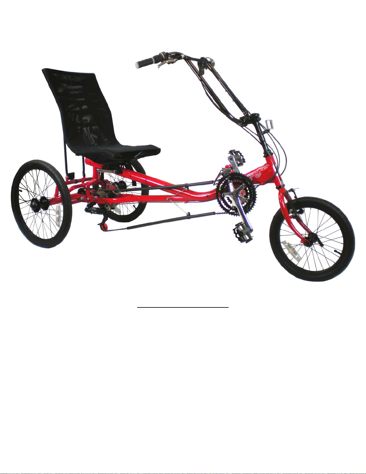
AmTryke Adult Recumbent Model JT2000 #50-FC-2000
TOOLS Needed for Assembly
5 mm Allen Wrench
8 mm Socket or Wrench
10 mm Socket or Wrench
14 mm Socket or Wrench
15 mm Socket or Wrench
22 mm Socket or Adjustable Wrench
Needle Nose Pliers W/ Side Cutters
Phillips Screw Driver
Revise Date: 8/06/09 1 of 29
Page 2

Table of Contents
Rear Deck Assembly Page 3
Front Tire Installation Page 5
Attaching Rear Deck to Main Frame Page 6
Leg Supports Page 7
Main Steering Installation Page 8
Attaching Seat Frame to Main Frame Page 10
Attaching Seat Cover Page 12
Front Reflector Page 13
Front Brake Page 14
Cable Retainer Page 16
Wheel Reflectors Page 18
Maintenance Page 19
Revise Date: 8/06/09 2 of 29
Page 3
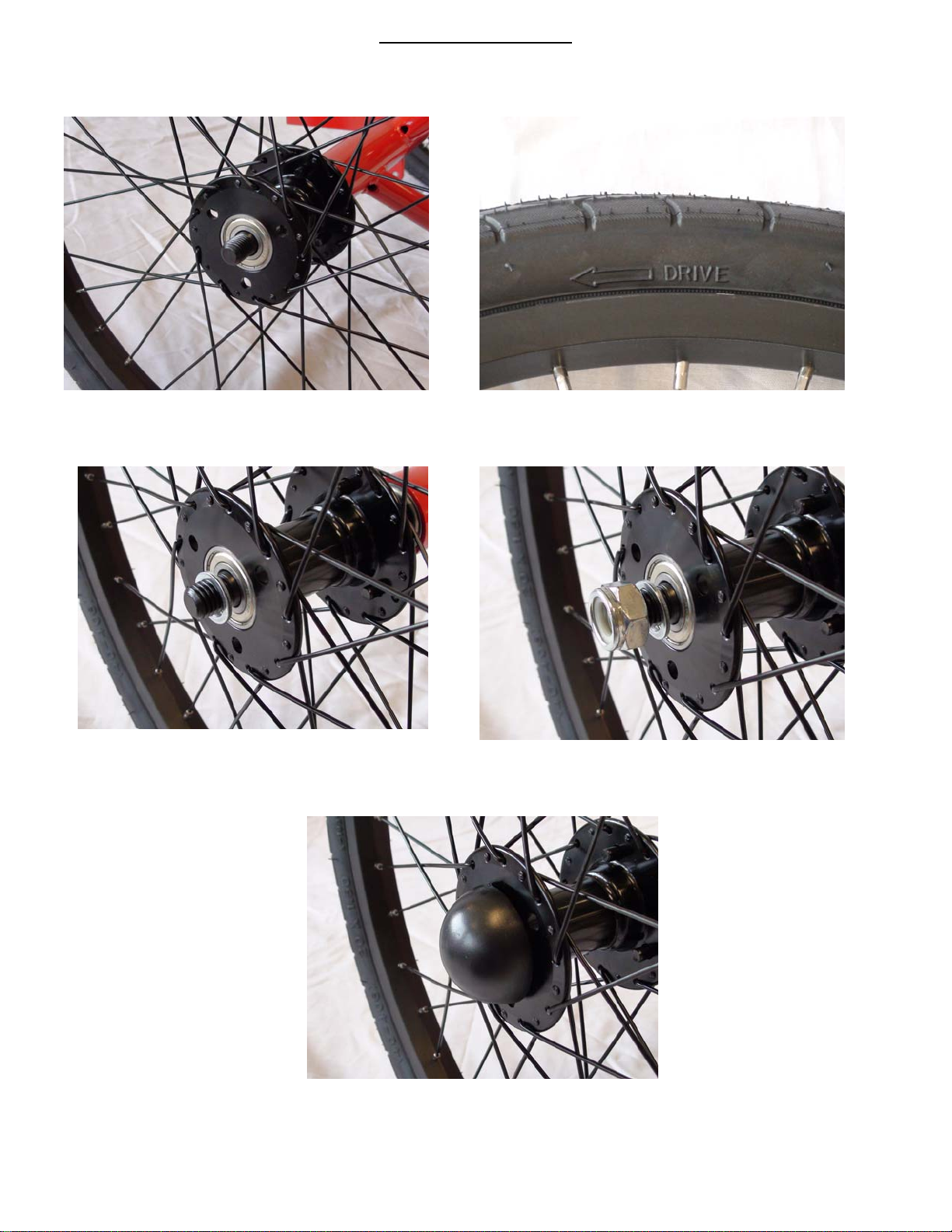
Rear Deck Assembly
1) Remove the 22mm nuts & flat washers from both ends of axle, slide wheel over each side, pay attention
to tire.
directional arrow.
2) Slide flat washer over each side and then thread a 22mm nut on each side. Tighten using a 22mm socket or
adjustable wrench, do not over tighten as wheel bearing we be damaged.
3) Install black round caps on each side, lightly tap to secure in place.
Revise Date: 8/06/09 3 of 29
Page 4
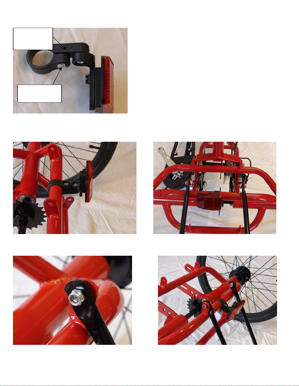
4) Install red reflector on bracket for rear deck using Phillips screw driver, bracket will have B-2 stamped on it.
B – 2
stamped
Clamping
Screw
5) Using Phillips head screw driver remove clamping screw from bracket, open clamp and install on rear, thread
clamping screw and tighten.
6) Install seat support bracket to rear deck using two 5mm Allen bolts & nuts. Use a 10mm Socket or Wrench & a 5
mm Allen Wrench to tighten.
Revise Date: 8/06/09 4 of 29
Page 5
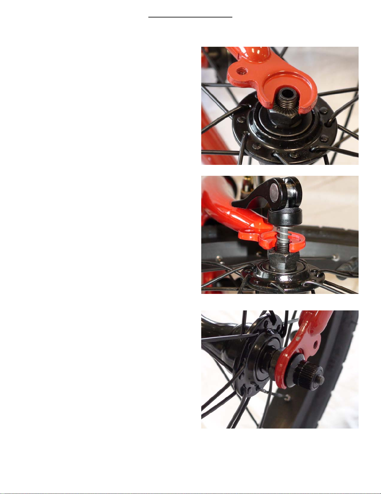
Front Tire Installation
1) Remove two black plastic thread protectors located on each end of axle.
2) Using the thin black quick release axle, remove the thumb nut from one side and one spring.
3) Place front tire in front fork.
4) Slide shaft of quick release axle through center of
rim.
5) Install spring on other side with narrow end pointing inwards, thread thumb nut back on and tighten.
Revise Date: 8/06/09 5 of 29
Page 6
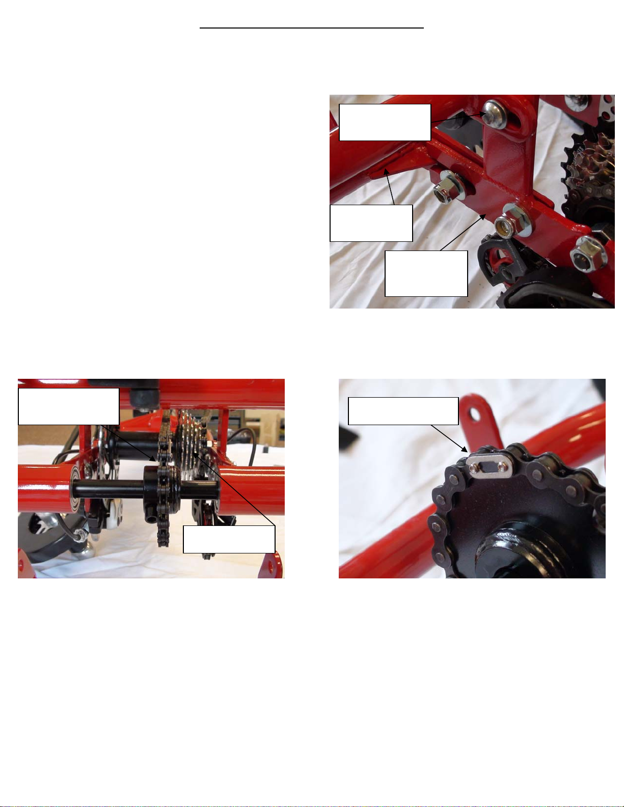
Attaching Rear Deck to Main Frame
1) Slide rear deck into main frame.
2) Using four large lag bolts, 4 large flat washers and four large nuts attach rear deck to main frame, use a 15mm
socket or wrench to tighten nuts. Do not tighten up completely at this point.
3) Install chain from main hub to rear axle sprocket.
Rear Axle
Sprocket
Main Hub
4) Using a pair of needle nose pliers snap the master link in place.
5) Pull back on the rear deck to tighten the chain, while pulling back tighten the four 15mm nuts using a 15mm
socket or wrench.
6) Install two upper support Allen bolts, washers and nuts using a 5mm Allen wrench & 13mm wrench. There is
one on each side of the rear deck.
Upper Support
Allen Bolt
Rear Deck
Main Frame
Master Link
Revise Date: 8/06/09 6 of 29
Page 7
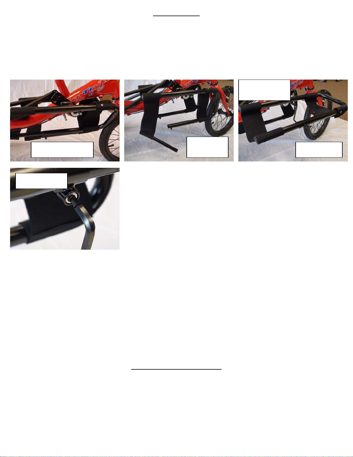
Leg Supports
1) The leg supports are already installed. Due to constraints in packaging you will need to position them.
2) First, remove the tube from the right leg support. Pivot the leg so it is 90 degrees to the main frame of the
tricycle. Replace the tube.
3) Rotate the left side leg support to a similar position.
4) Don’t tighten until final set-up.
Pivot
Downward
Remove
Tube
Insert Tube
Initial Appearance
Tighten
Main Steering Installation
1) Slide the hand crank steering tube over the steering stem of the main frame, note location of chain guides before
installing. Inside chain guide fits underneath bolt for tightening steering tube to stem. Outside chain is just
above holes in leg support bracket.
Revise Date: 8/06/09 7 of 29
Page 8
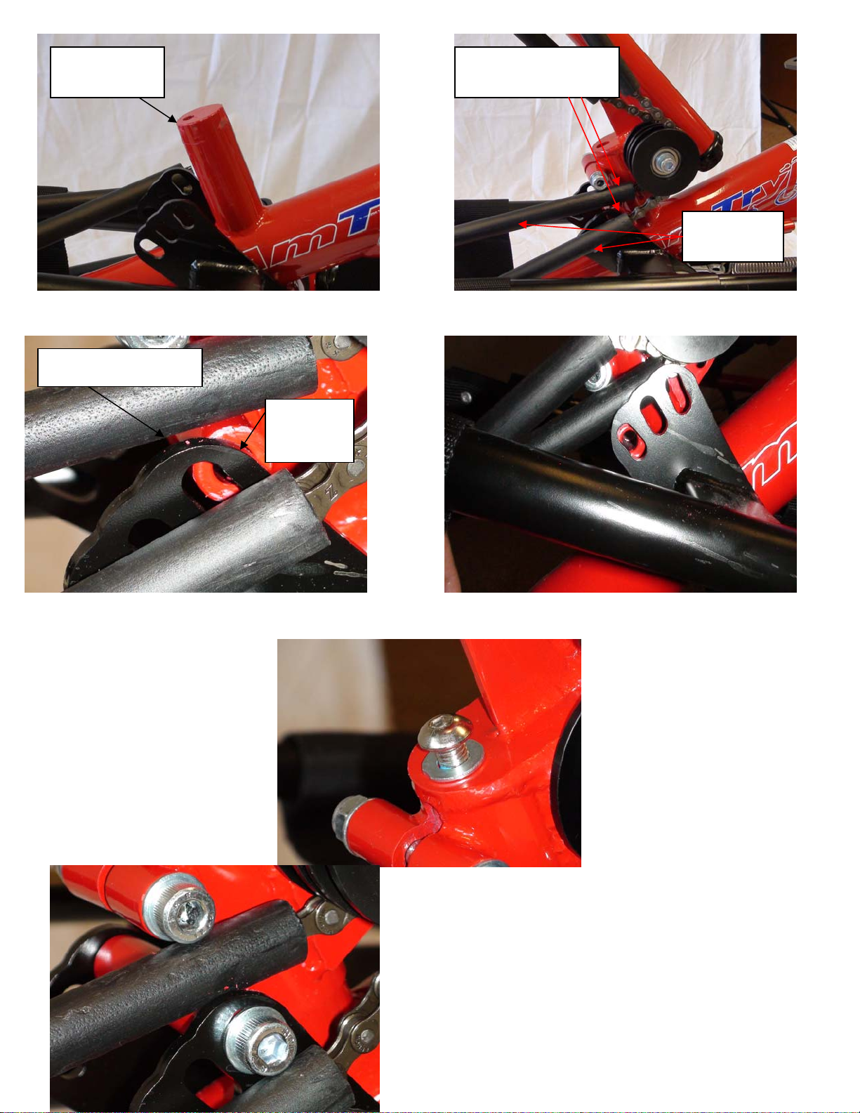
Steering
Stem
2) Pivot leg support bracket so the hole in support bracket aligns with hole in main steering tube.
Leg Support Bracket
Hole not
aligned
3) Thread the 1” 5mm Allen head bolt with flat washer through the center steering stem hole.
Chain guides
location
Hole aligned
Chain
Guide
4) Insert 6mm 3 ½” bolt through the support bracket and
through the main steering tube and out the other side,
install one flat washer and thread 13mm nut, tighten
using 13mm socket or wrench and 6mm Allen wrench
Revise Date: 8/06/09 8 of 29
Page 9
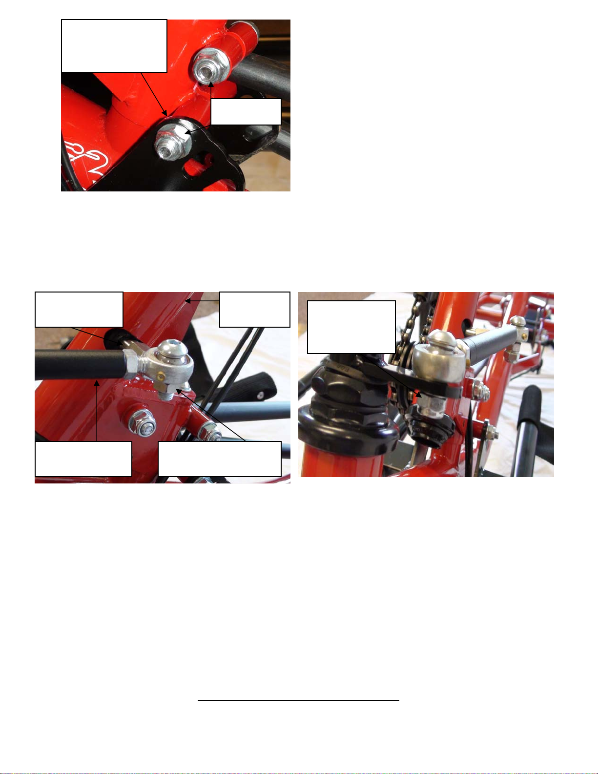
5) Install handgrips, shift/rear brake goes on the right side, while the front hand brake is positioned on the left, the
6) Install the steering linkage; remove the two nuts and flat washers already installed.
7) Using a 5mm Allen wrench thread the screw through the steering stem attachment, slide one flat washer over
8) Slide flat washer over front screw and thread 13mm nut, use a 5mm Allen wrench and 13mm wrench or socket
9) Once installed, adjust steering by turning black tube adjustment rod until satisfied tryke is positioned to steer
13mm nut with flat
washer.
Tighten
right side threads in clockwise while the left side threads in counter clockwise.
the exposed thread and thread the 13mm nut, tighten.
Stem
attachment
Steering Linkage
to tighten.
straight ahead.
13mm nut and flat
washer
Steering
Stem
13mm nut and
flat washer
Attach Seat Frame to Main Frame
Revise Date: 8/06/09 9 of 29
Page 10
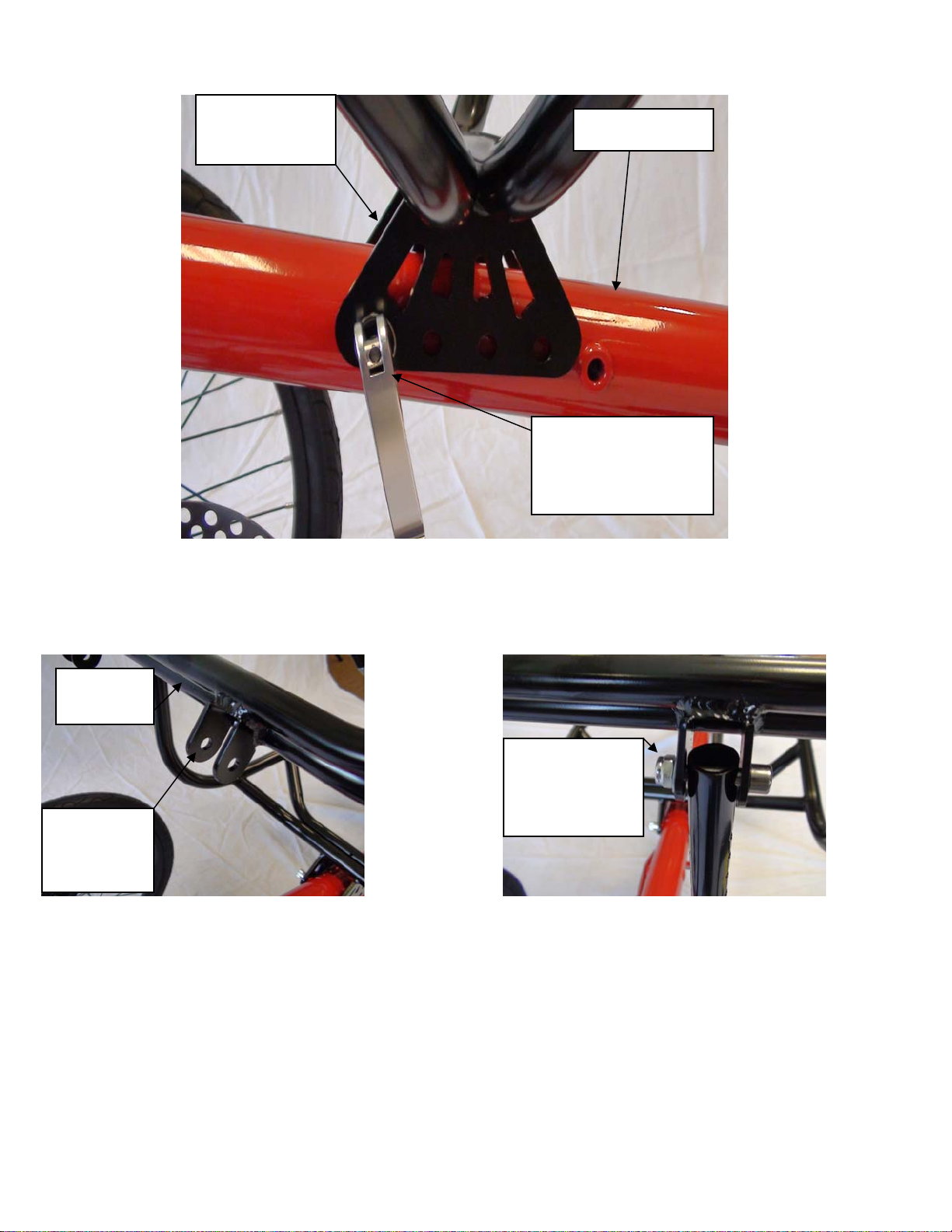
1) Place main seat frame mounting bracket over main frame so that one hole in the seat bracket aligns with a hole
in main frame. Remove thumb nut from silver cam lock lever and insert shaft through seat bracket and through
main frame, thread thumb nut on and lock down lever.
2) Install two short seat supports on back of main seat frame using two long shafted Allen bolts, two flat washers
and two nuts. Tighten using a 10mm wrench or socket and 5mm Allen wrench.
Seat
Frame
Short
support
mounts
Seat Frame
Bracket
Main Frame
Quick release with
cam lock lever
inserted through
frame.
10mm nut and
5mm Allen
bolt
Revise Date: 8/06/09 10 of 29
Page 11
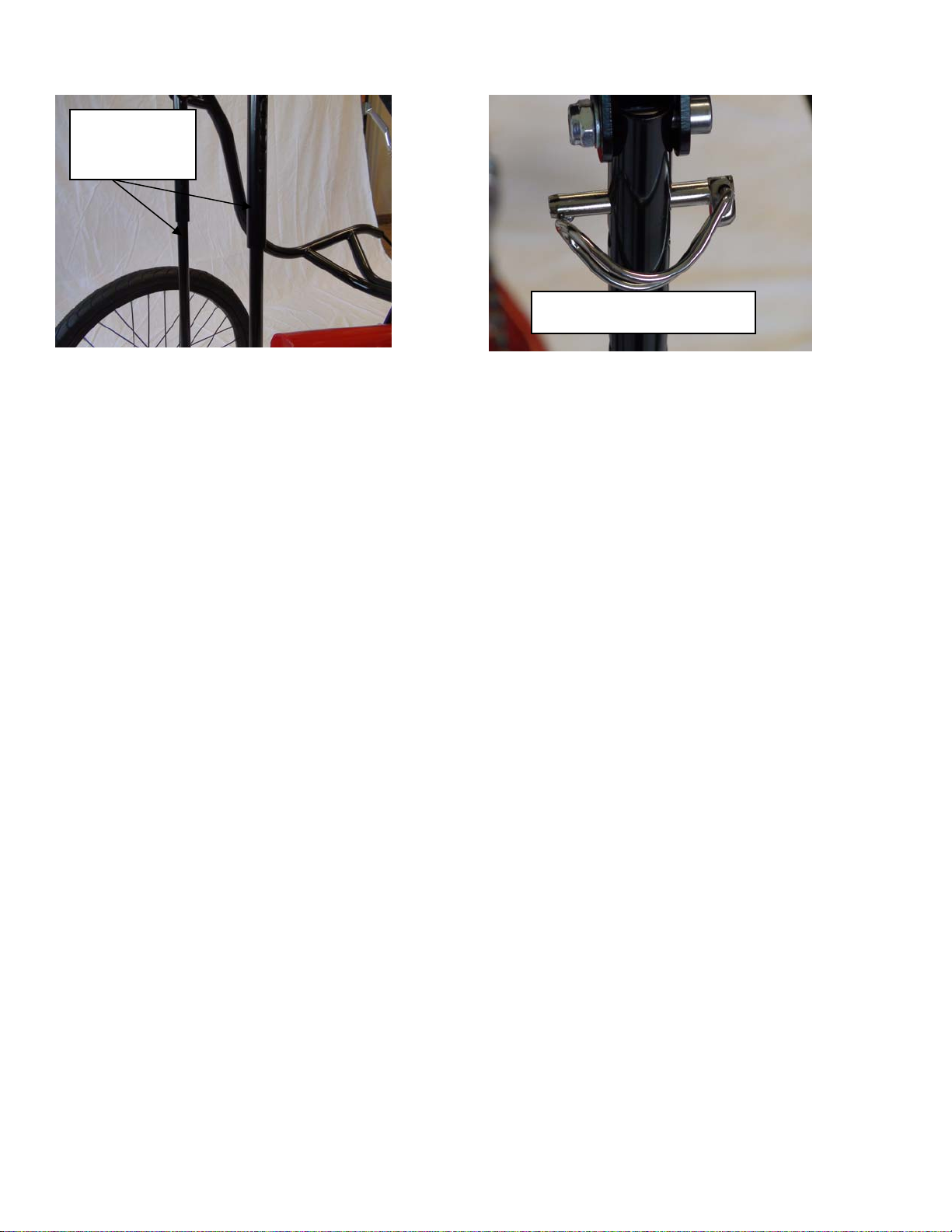
3) Slide long support bars inside of short support bars, align holes in each and insert in each one a clevis pin
W/snap ring.
Seat Support
Bars.
NOTE: The angle of the seat is determined by adjusting the height of the support bars, the lower the adjust the
greater the angle.
By moving the main seat frame forward or backward to other holes in the main frame will either decrease or
increase the arm/leg travel for either taller or shorter riders.
Clevis pin with snap ring
Revise Date: 8/06/09 11 of 29
Page 12
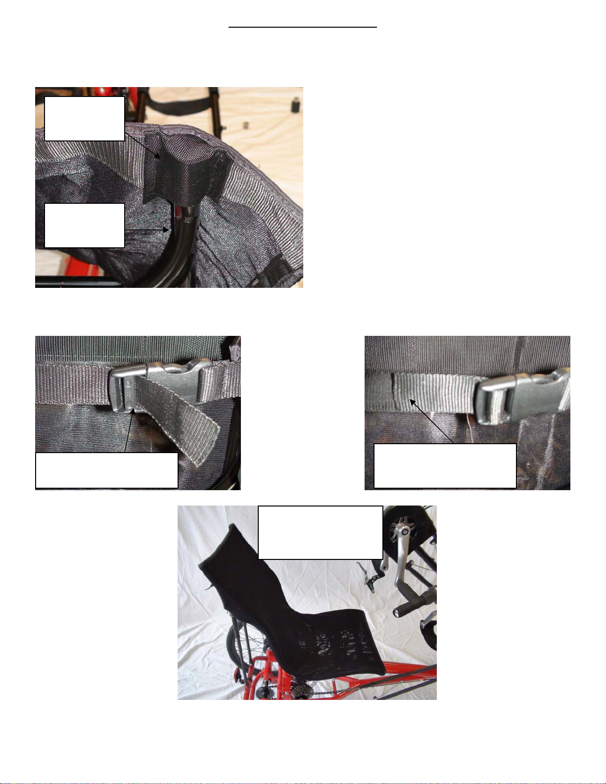
Attaching the Seat Cover
1) Along one edge of the seat cover are straps and the other edge are buckles. On the other two edges are pockets
to slide the seat cover over the main seat frame.
2) Slide the seat cover over the main seat frame.
Pocket in
seat cover
Main seat
frame
3) Lace the straps through the buckles then tighten the straps by pulling them. The cover will conform to the seat
frame.
Lace strap through buckle
as shown above.
Finished seat cover
should look like this
one.
Pull on excess strap to
tighten.
Revise Date: 8/06/09 12 of 29
Page 13
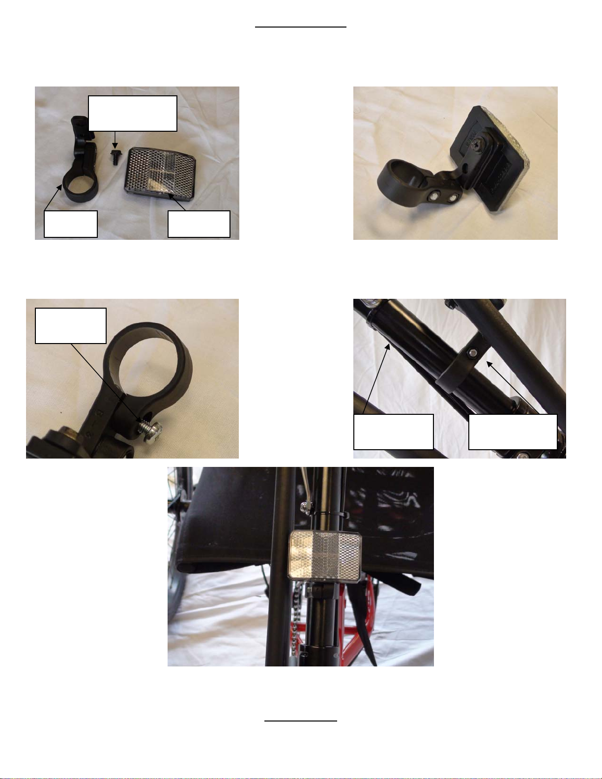
Front Reflector
1) Attach reflector to bracket, use Phillips head screw.
Phillips head
screw
Bracket
2) Remove clamp screw, open clamp and place over steering stem tube.
Clamp
Screw
Reflector
Steering stem
tube
Reflector
bracket
Front Brake
Revise Date: 8/06/09 13 of 29
Page 14
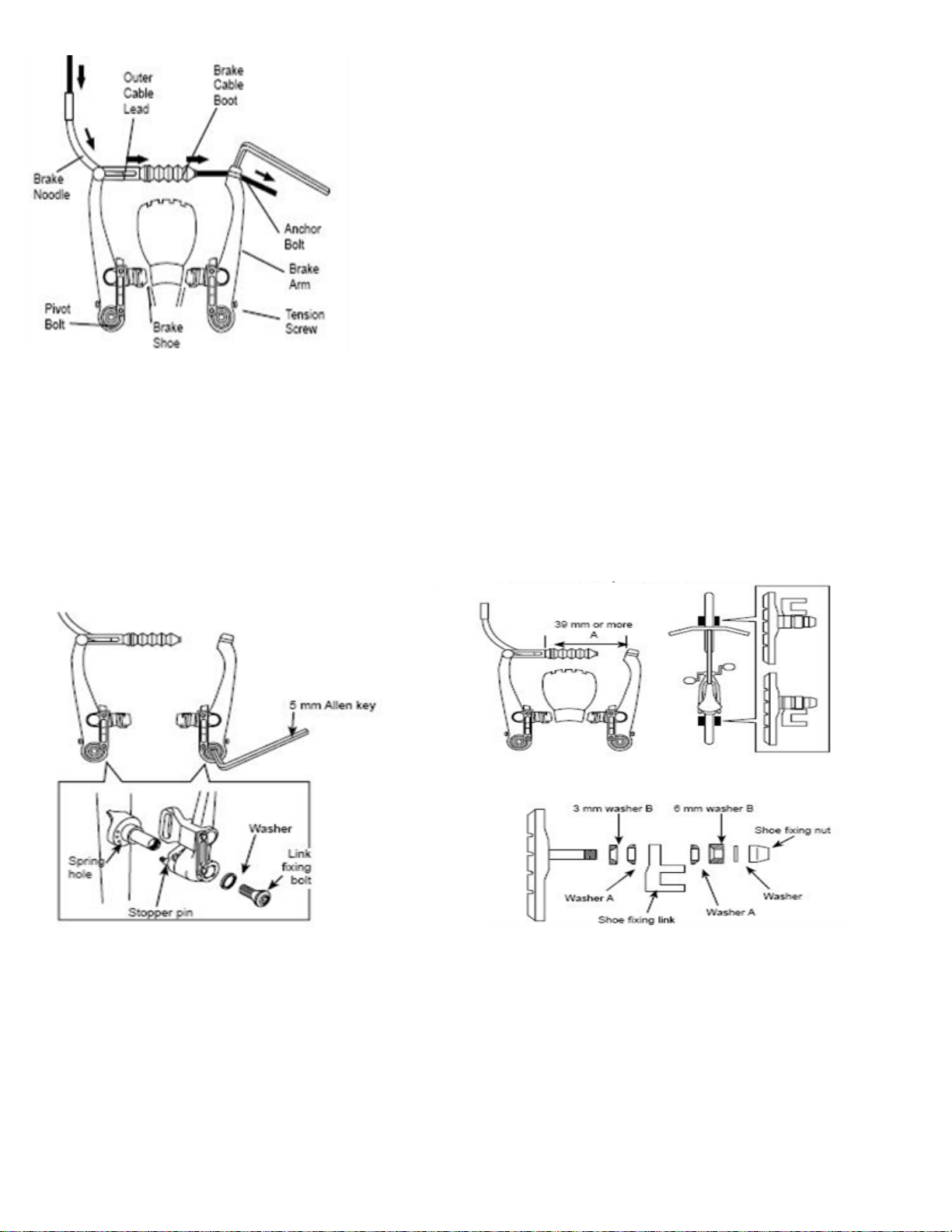
V-Brake
1. If fitted with V-Brakes, insert the brake body
into the center spring hole in the frame mounting
boss, and then secure the brake body to the frame
with the link fixing bolt.
V-Style Brakes
If not already assembled, take the brake noodle from the parts box and
slide the cable through the larger opening. The cable housing will then
seat into the end of the noodle. Slide the cable through the cable lead on
the end of the left brake boot arm; this will cause the noodle to fit into the
lead. Slip the brake cable boot over the cable and position it between both
brake arms. Next loosen the 5mm anchor bolt at the end of the right
brake arm and slide the cable under the retaining washer. Pull the slack
out of the cable making sure a distance of 39mm or more remains
between the end of the lead and the start of the anchor bolt. Once the
cable is secured to the brake arms, engage the brake lever several times,
checking the position of the brake shoes at the rim. The brake shoes
should be 1mm away from the rim when in a relaxed position. When the
brake lever is engaged, the brake shoe should hit the rim flush (never the
tire) with the front brake pad touching the rim slightly before the rear.
This is called “toeing-in” your brake shoe. If this position is not achieved,
adjustments to the brake shoe are required. Loosen the brake shoe
hardware and reposition the brake shoe. It may take several shoe and
cable adjustments before the required position is accomplished.
2. While holding the shoe against the rim, adjust the amount
of shoe protrusion by interchanging the position of the B
washers (i.e. 6 mm and 3 mm) so that dimension A is kept at
39 mm or more.
3. While holding the shoe against the rim,
Revise Date: 8/06/09 14 of 29
tighten the shoe fixing nut.
5. Adjust the balance with the spring tension adjustment
screws.
Page 15
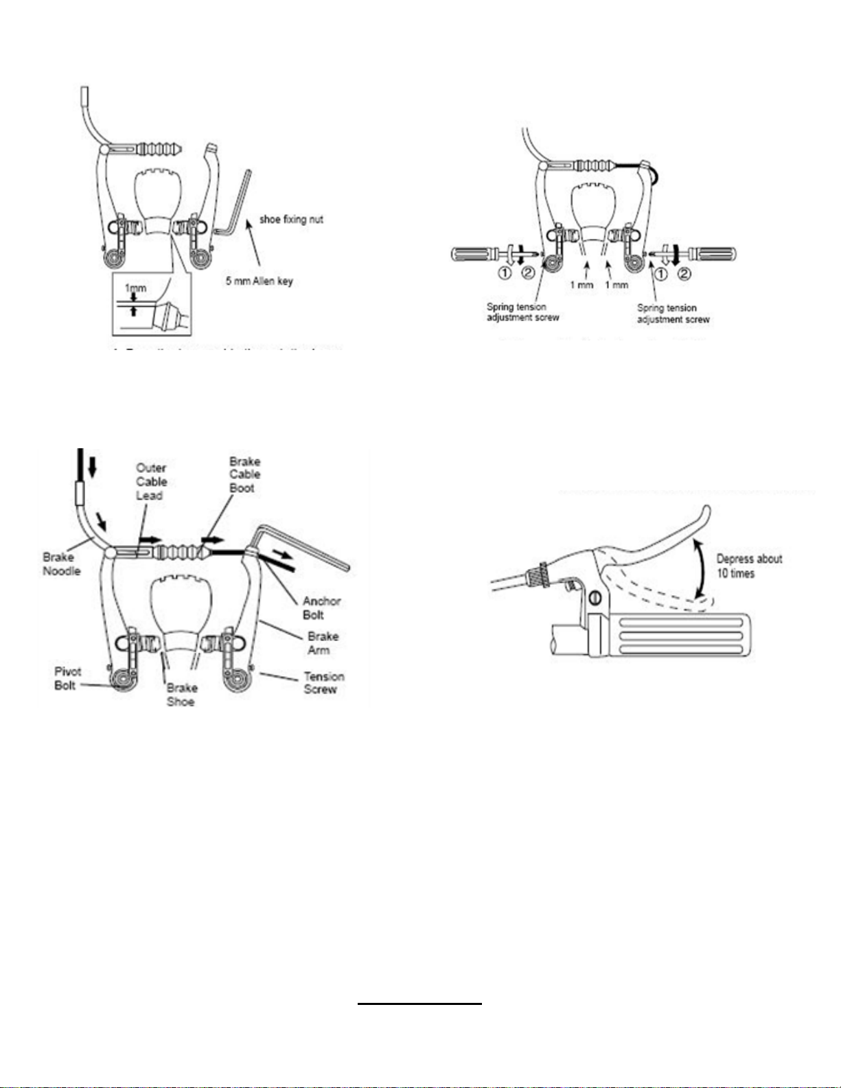
4. Pass the inner cable through the inner cable lead. Set the
cable with the clearance of 1mm between each brake pad
and the rim, tighten the cable fixing bolt.
Cable Retainer
6. Depress the brake lever about 10 times as far as the
grip to check that everything is operating correctly and
that the shoe clearance is correct before using the
brakes.
Revise Date: 8/06/09 15 of 29
Page 16
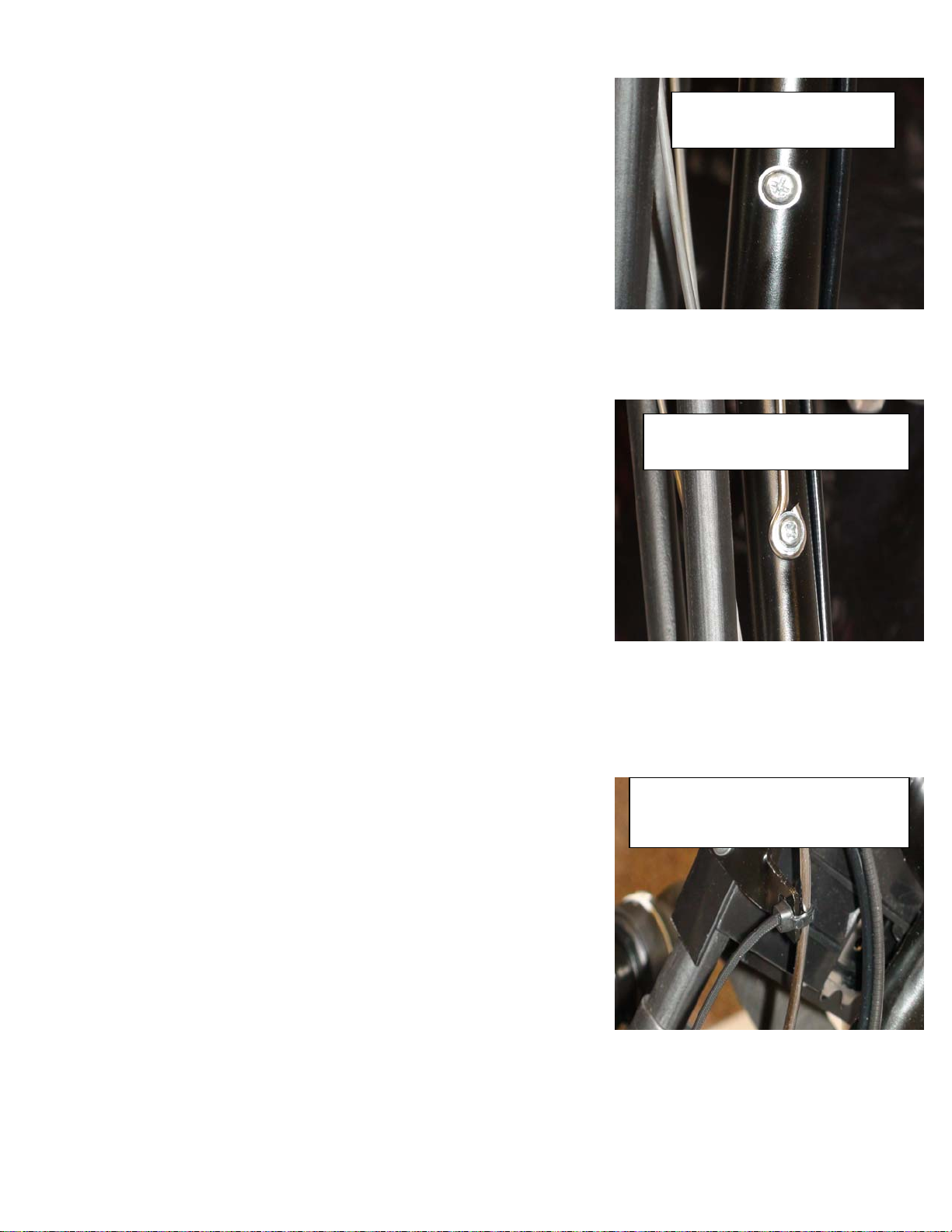
1) Remove the Phillips head screw located on the steering stem tube.
2) Put screw through lower eyelet of cable retainer and thread back into steering stem tube.
3) Attach the cable retainer to upper chain guard bracket using a zip tie. Clip off excess zip tie.
Phillips head screw on
steering stem tube.
Phillips head screw through
lower eyelet of cable retainer.
Cable retainer attached to upper
chain guard bracket with zip tie.
Revise Date: 8/06/09 16 of 29
Page 17
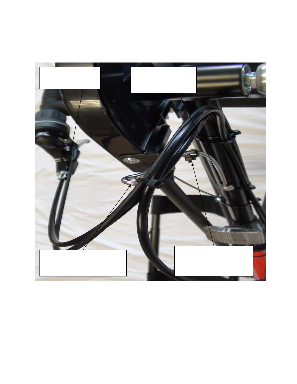
4) Use a zip tie to attach the three cables to the retainer; this will prevent the cable from wrapping around the hand
grips during pedaling.
5) Use the remaining zip ties and secure the cable to the steering stem tube.
Gear shift cable and
rear brake cable.
Rear brake, Front brake and Gear
shift cables attached to the cable
retainer with zip tie.
Cable retainer secured to
steering stem tube with
screw.
Cable retainer attached to
upper chain guard bracket
with zip tie.
Revise Date: 8/06/09 17 of 29
Page 18
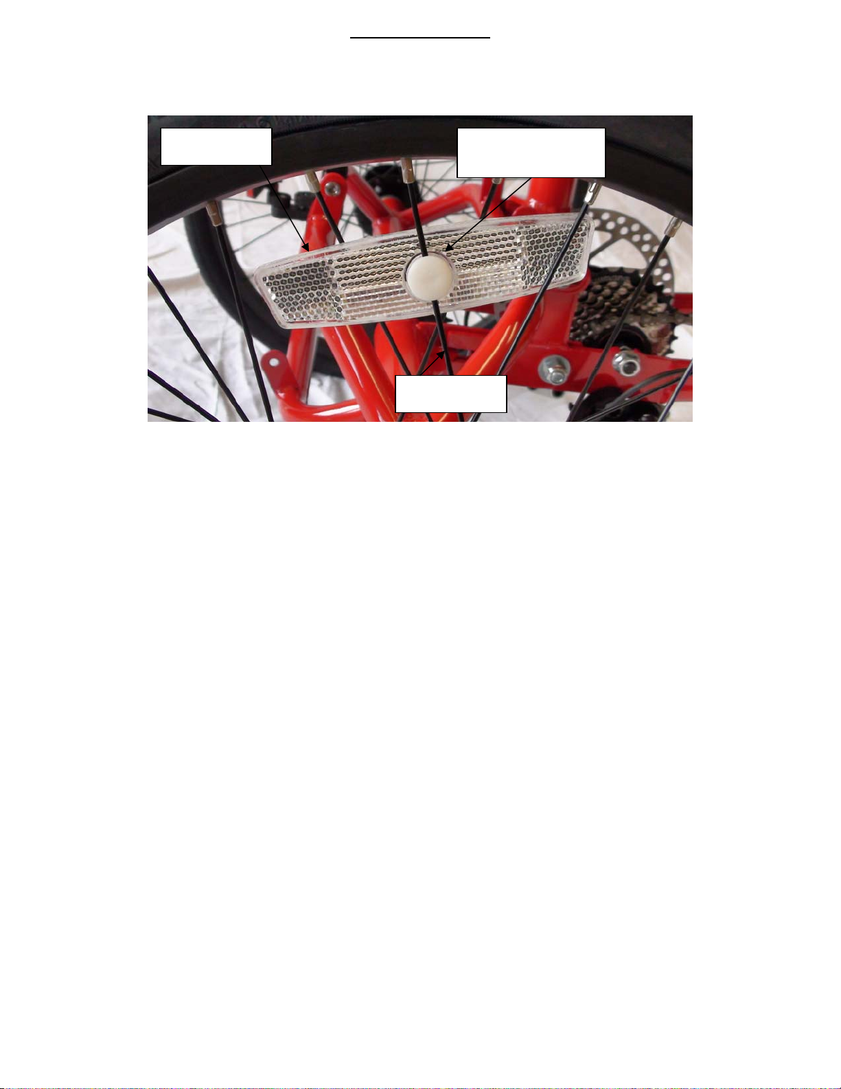
Wheel Reflectors
1) Place the reflector in an area on the rim behind a single spoke with two on the opposite side. Align the front
spoke with the slot in the reflector.
Reflector
Single spoke
Reflector holding
pin
2) Insert the reflector holding pin with the slotted end going over the spoke into the hole in the reflector. Press
firmly until you hear it click into place.
Revise Date: 8/06/09 18 of 29
Page 19
Maintenance
As is with all other bikes and vehicles that use a chain for the drive line, the chain may come off the sprocket and need
to be reinstalled. This next section will serve as a guide on how to reinstall the chain should it come off.
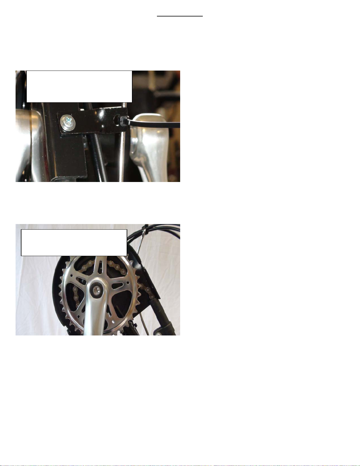
1) Remove the Phillips head screw on the front of the chain guard and the 8mm nut located behind it that secures the
two halves of the chain guard together and holds the upper chain guard bracket in place.
Remove Phillips head screw and
8mm nut located behind it. (not
shown the 8mm nut)
2) The outer chain guard cover will easily remove by lifting up on it; let it rest on th e hand grip.
Outer chain guard cover removed
chain and sprocket now exposed
Revise Date: 8/06/09 19 of 29
Page 20
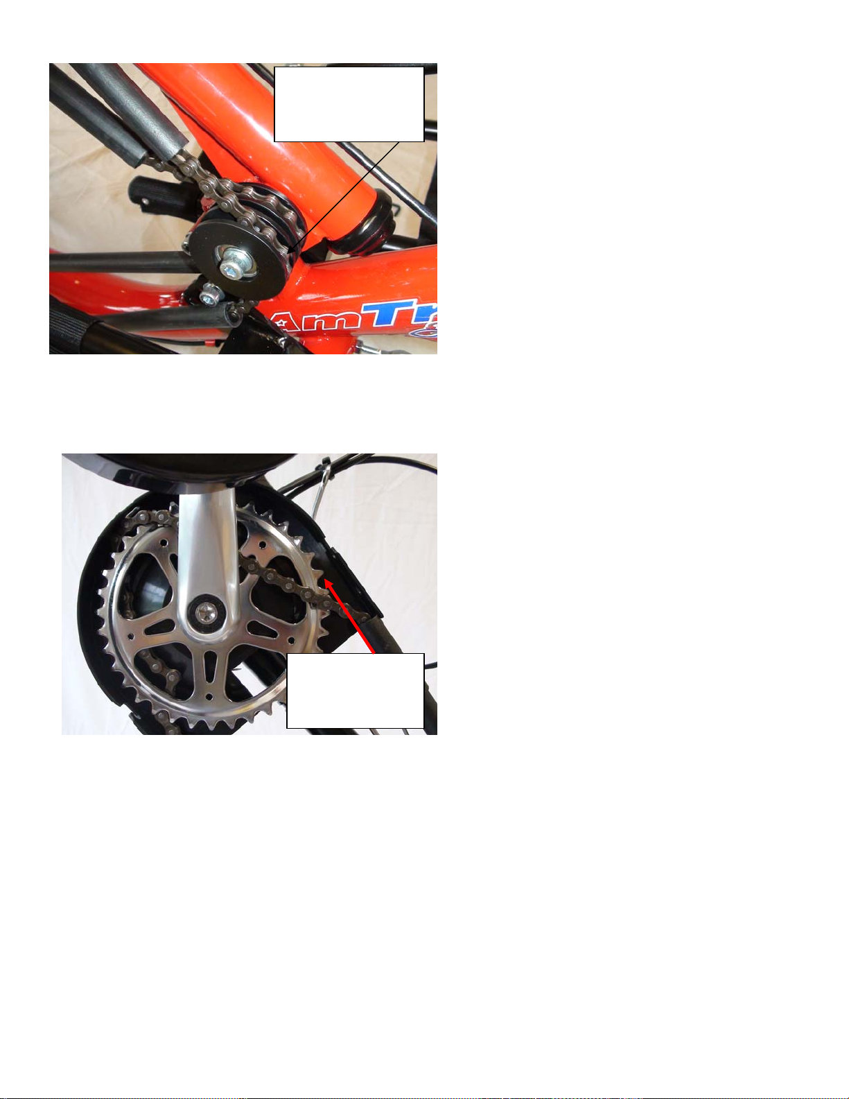
3) Remove the outer chain from the lower outer pulley slot located at the base of the steering stem tube.
Outer pulley at
base of steering
tube.
4) Use a screwdriver to lift the chain up in the front and turn the hand crank counter clockwise while doing so until it
grabs the chain and pulls it outwards.
Insert screw
driver here and
lift up on chain.
Revise Date: 8/06/09 20 of 29
Page 21
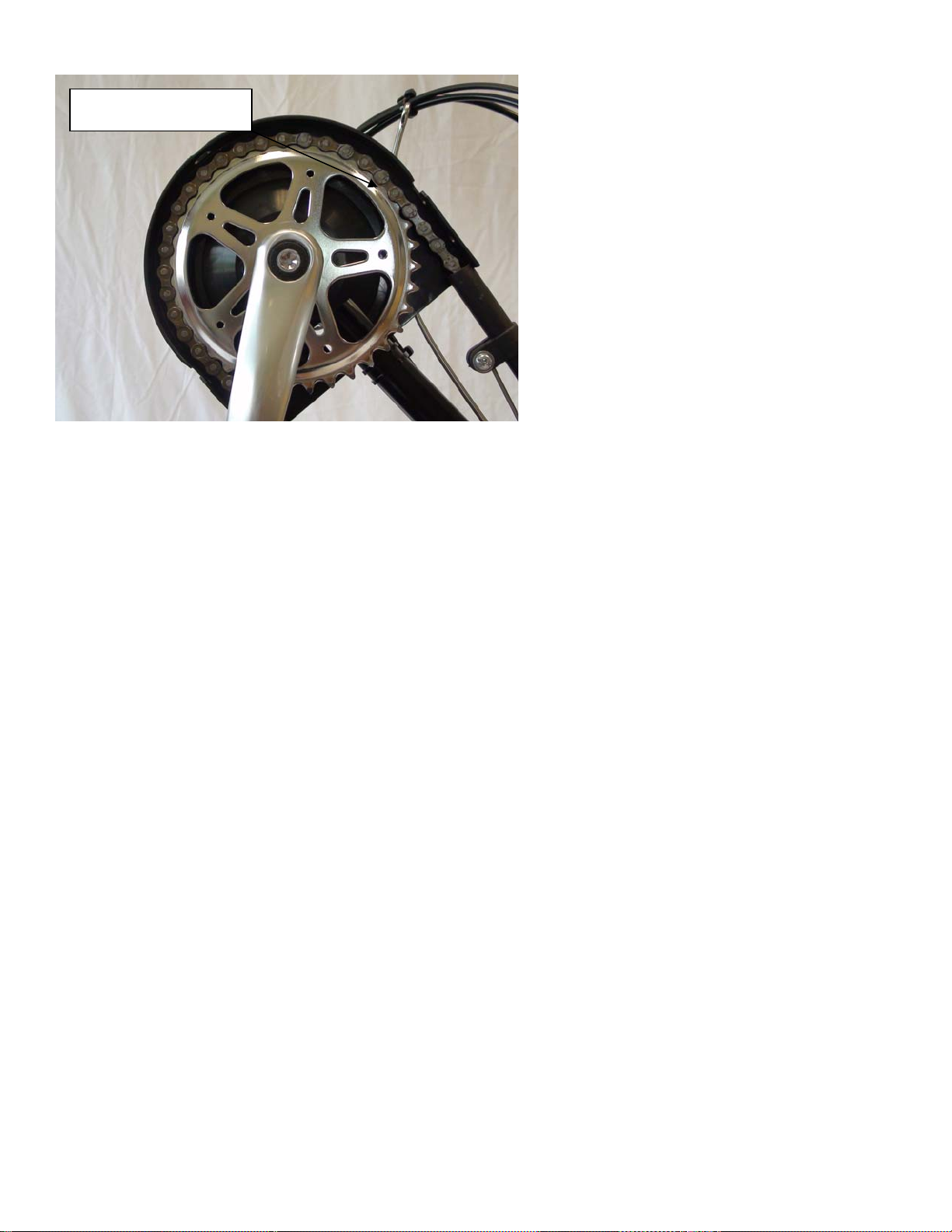
5) Place chain on front side of sprocket and rotate crank arm counter clockwise until chain is on sprocket completely.
Front of Sprocket
6) Repeat steps 1, 2 & 3 in reverse to finish reinstalling the chain.
Revise Date: 8/06/09 21 of 29
Page 22
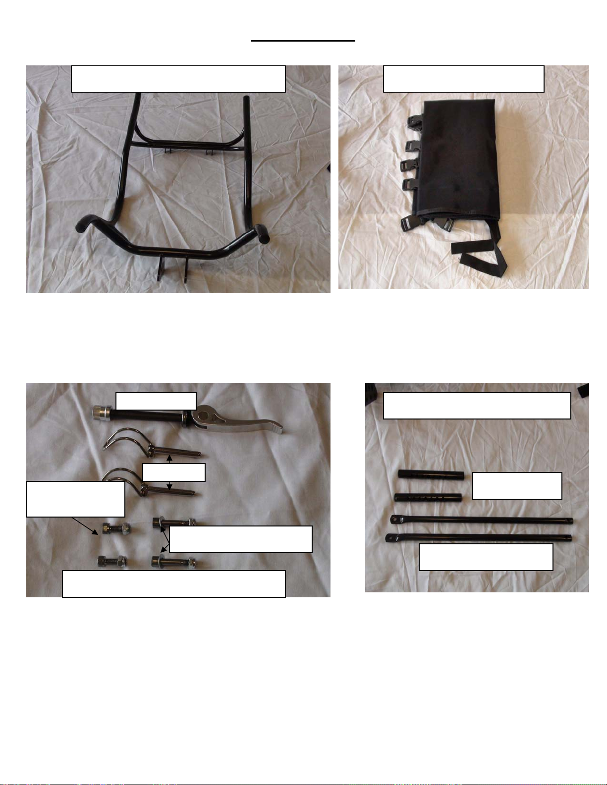
Q
Seating Assembly
Main Seat Frame (pages 10 to 12)
Seat cover (Pages 10 to 12)
uick Release
Seat support rods (Pages 10 to 12)
Clevis Pins
Long support rod
Allen bolts
Short support rods
Short support rod Allen bolts
Long support rods
Seat mounting hardware (Pages 10 to 12)
Revise Date: 8/06/09 22 of 29
Page 23
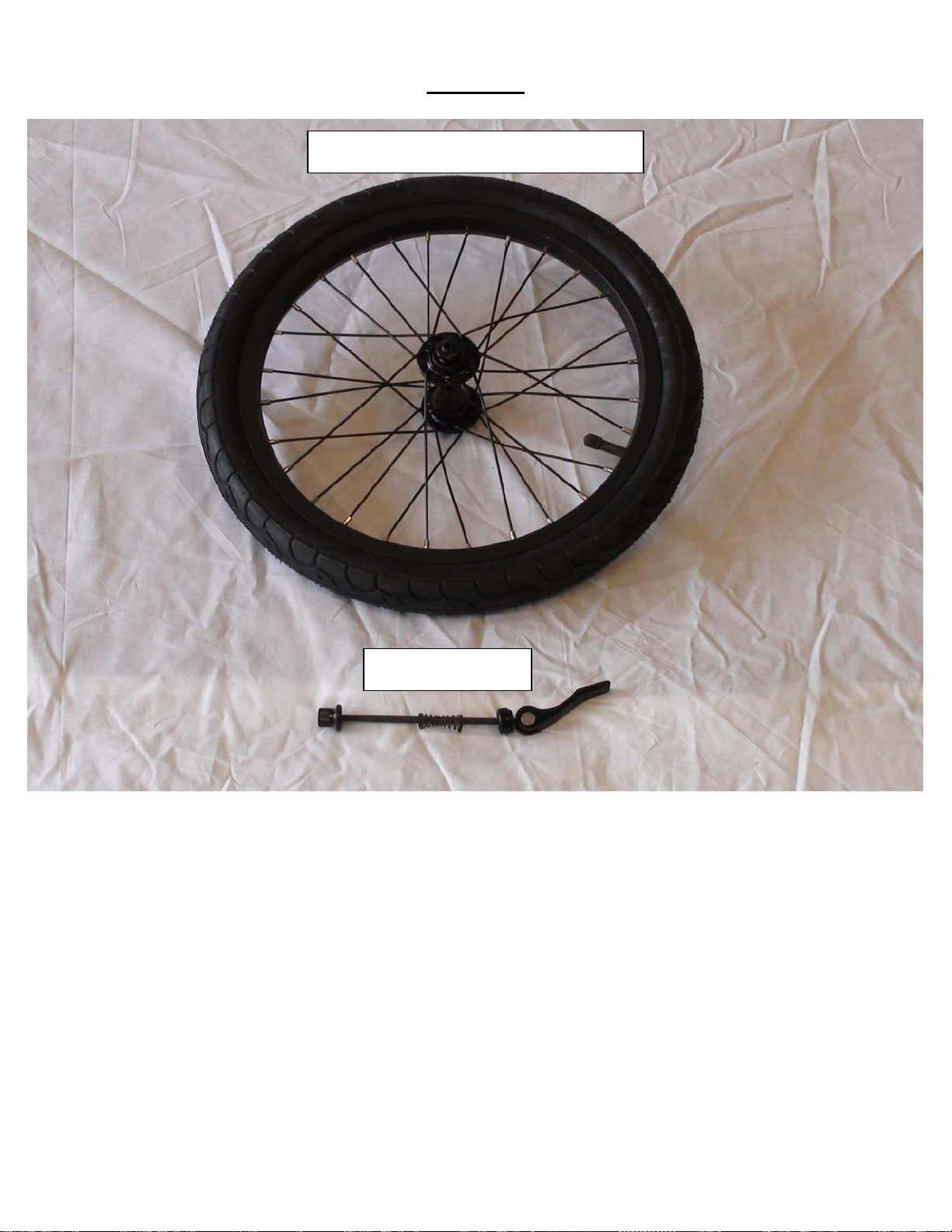
Front Tire
Front tire and quick release axle (Page 5)
Quick release axle
Revise Date: 8/06/09 23 of 29
Page 24
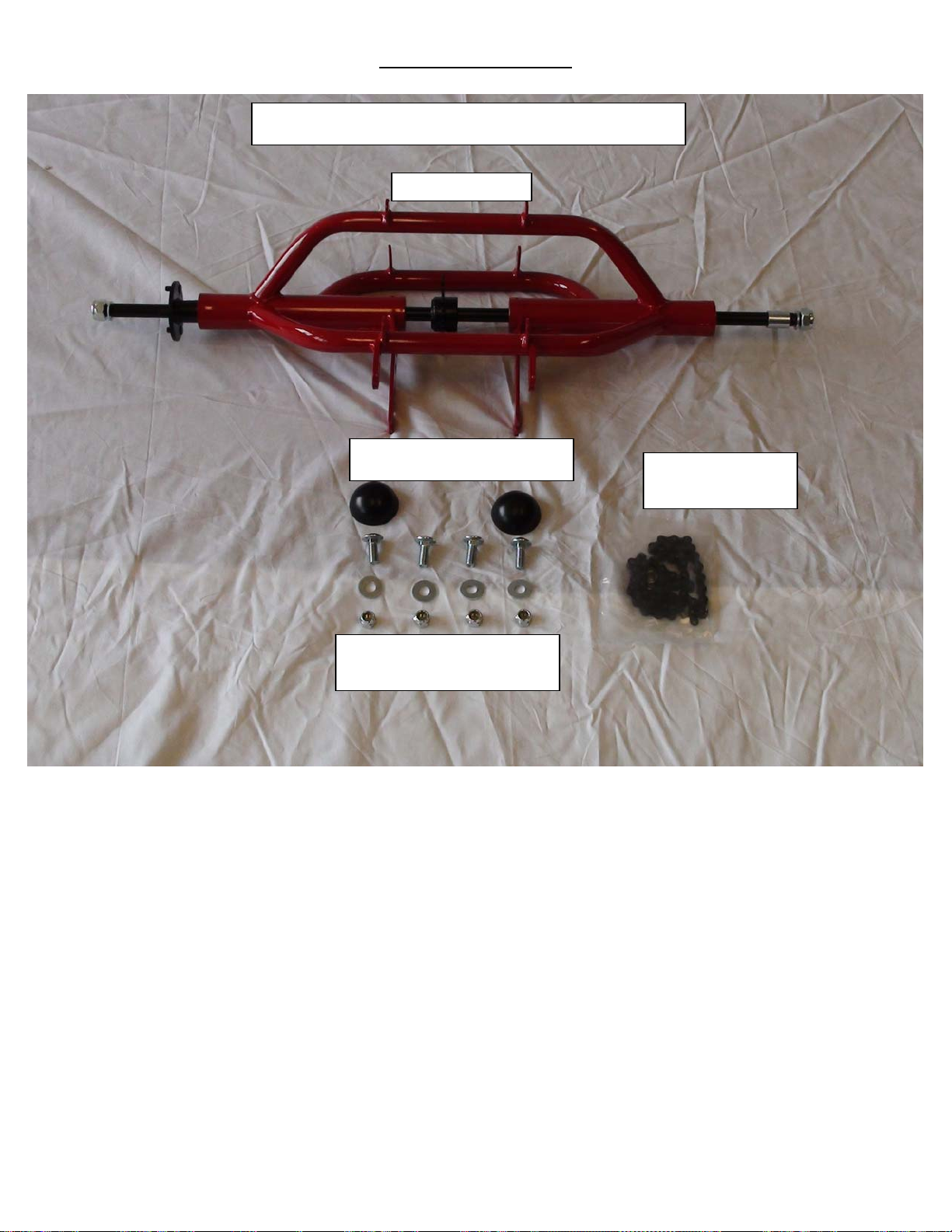
Rear Deck Assembly
Rear deck and mounting hardware (Pages 3 to 6)
Rear deck frame
Black round nut caps (page 3)
Rear deck frame to main frame
mounting hardware (Page 6)
Chain and master
link (Page 6)
Revise Date: 8/06/09 24 of 29
Page 25
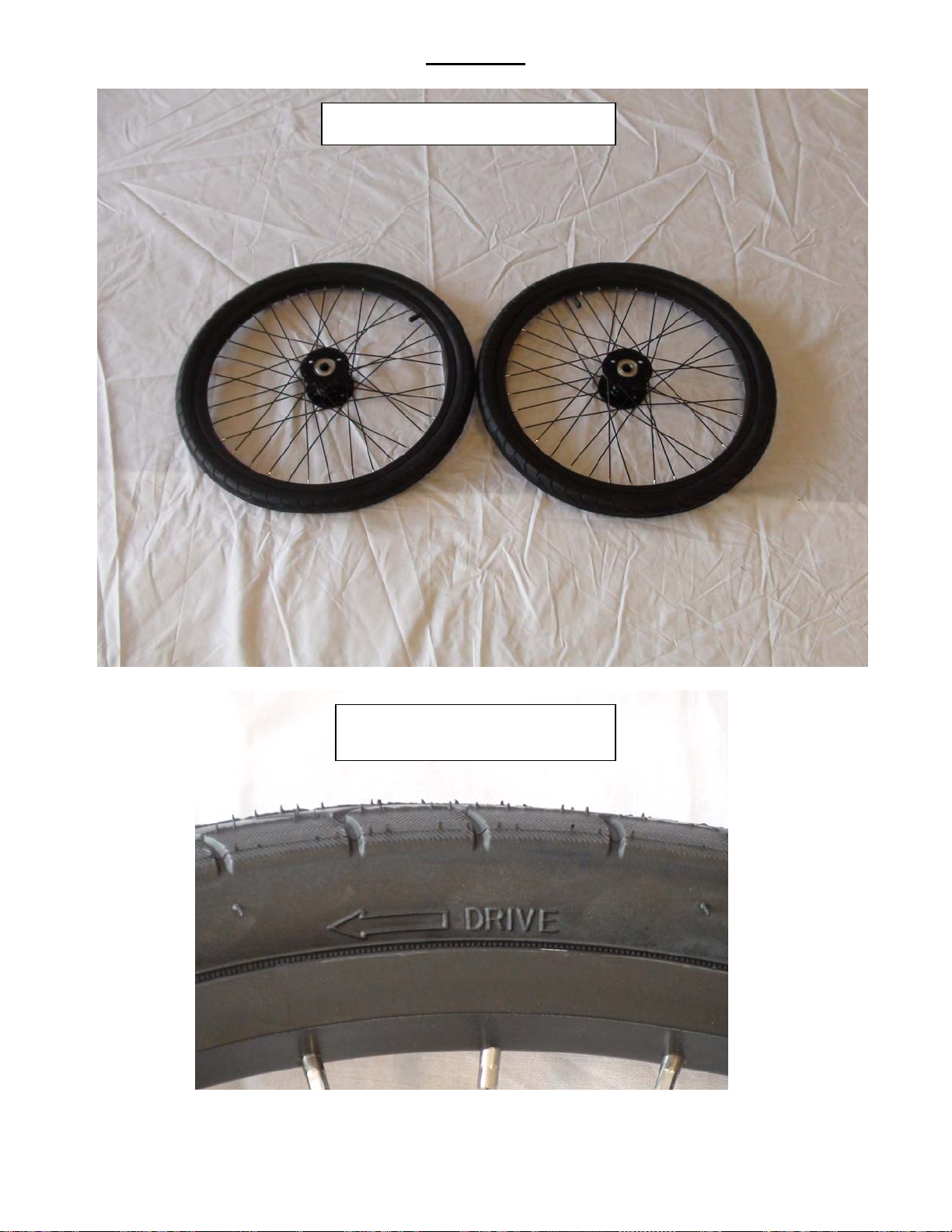
Rear Tires
Right and Left rear tires (Page 3)
Tire direction must be followed
Revise Date: 8/06/09 25 of 29
Page 26
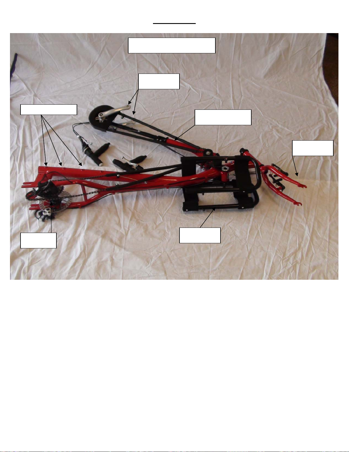
Main Frame
Main frame (Pages 6 to 10)
Hand cranks
Seat position holes
Main hub
Main Steering Tube
Front Fork
Leg Supports
Revise Date: 8/06/09 26 of 29
Page 27
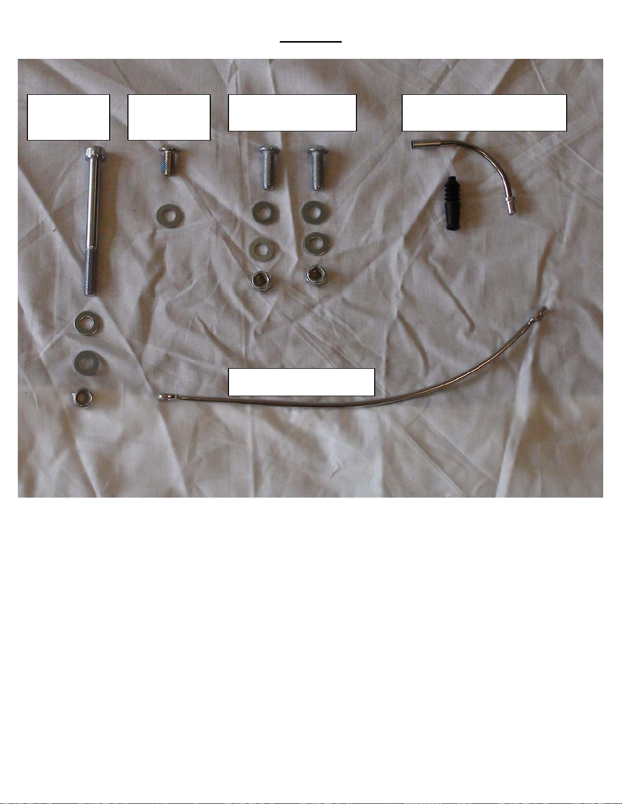
Hardware
Leg support
bolt, washers
and nut (Page 9)
Center steering
stem bolt and
washer (Page 8)
Upper support Allen bolts,
washers and nuts (Page 6)
Cable Retainer (Pages 16 to 17)
Brake noodle and cable cover
(Pages 14 to 15)
Revise Date: 8/06/09 27 of 29
Page 28
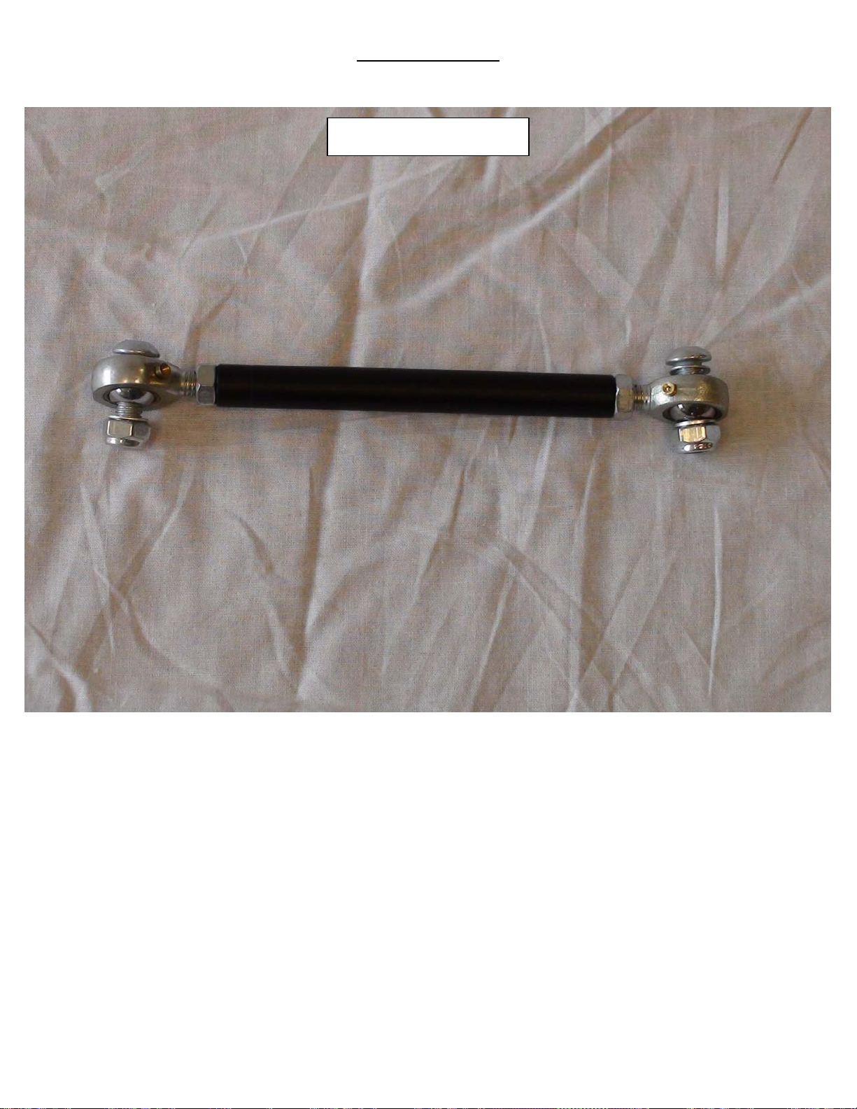
Steering Linkage
Steering Linkage (Page 9)
Revise Date: 8/06/09 28 of 29
Page 29
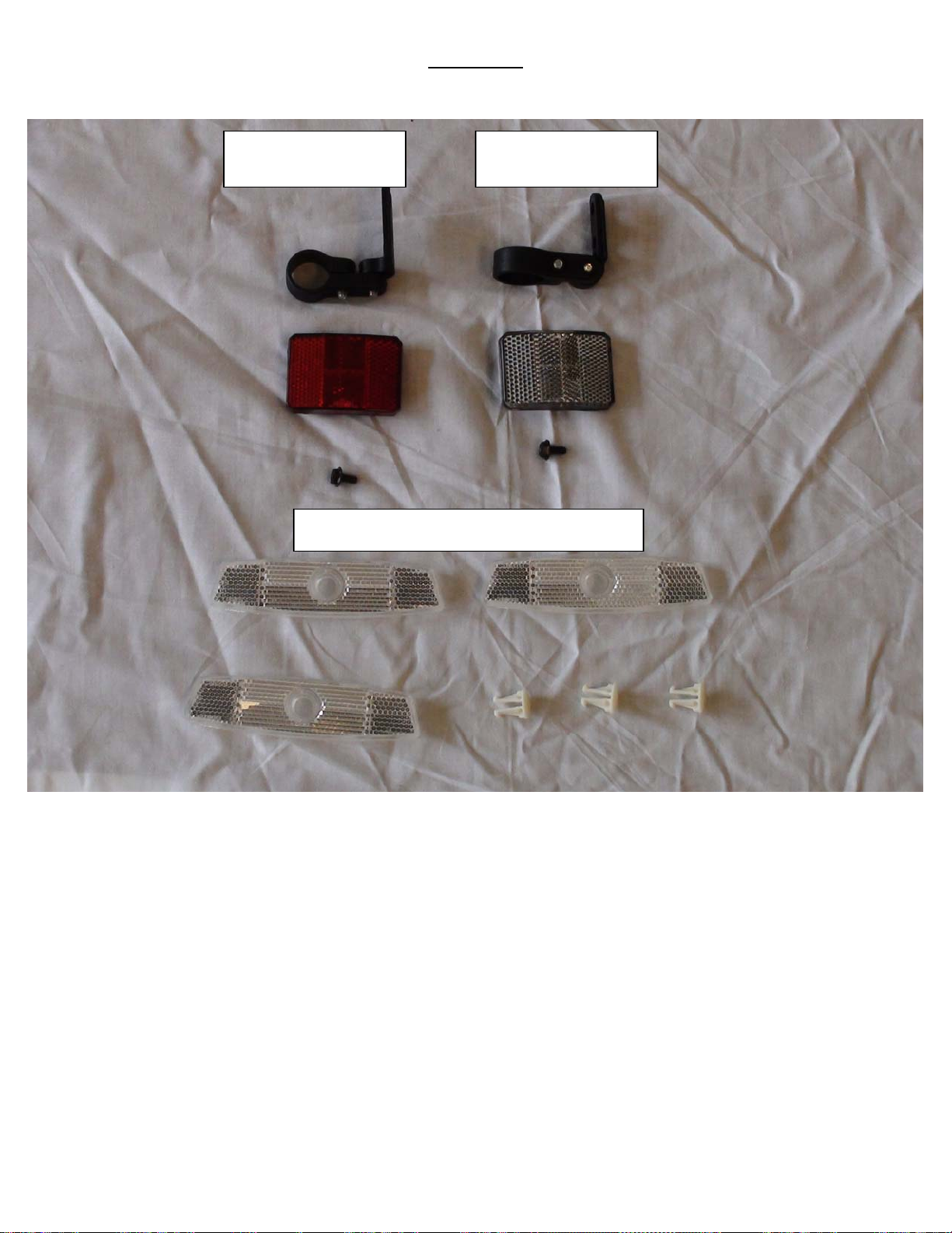
Reflectors
Rear reflector and
bracket (Page 4)
Wheel reflectors and spoke securing pins (Page 18)
Front reflector and
bracket (Page 13)
Revise Date: 8/06/09 29 of 29
 Loading...