

Page 1
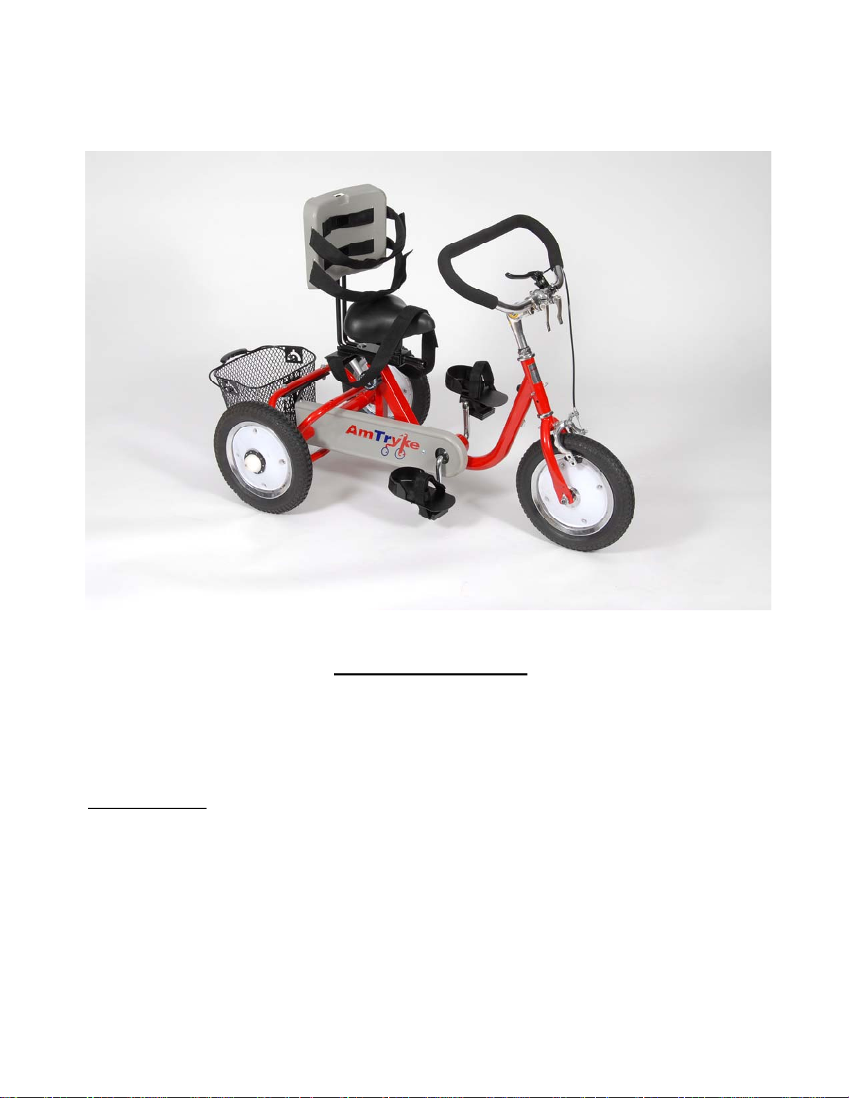
Amtryke® ProSeries Model #1412
50-FC-1412
Tools Needed for Assembly
8 mm Socket or Wrench 10 mm deep well socket or wrench
13 mm Socket or Wrench 14 mm Socket or Wrench
15 mm Socket or Wrench Needle Nose Pliers
Utility knife
Carton Contents
Carefully remove and lay out all parts from the carton so as not to scratch or lose any parts or pieces.
The shipping carton should contain:
1) Pedal Box – part PD-V3 ½ inch
2) Box marked with 0 and delta sign containing the seat assembly
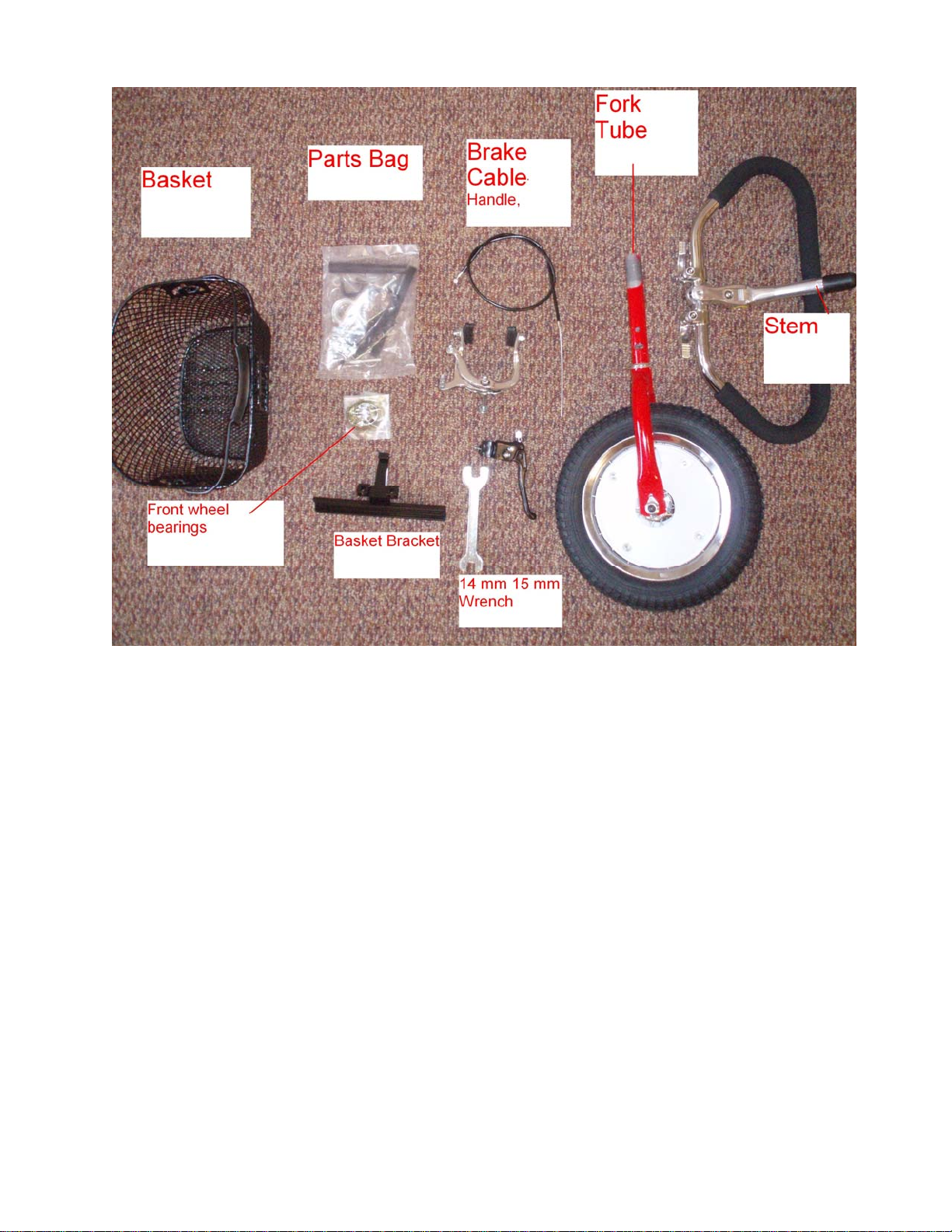
3) Parts Box - The pictured items on the parts page.
4) The main frame assembly.
Revised Date: 11/04/08 Page 1 of 12
Page 2
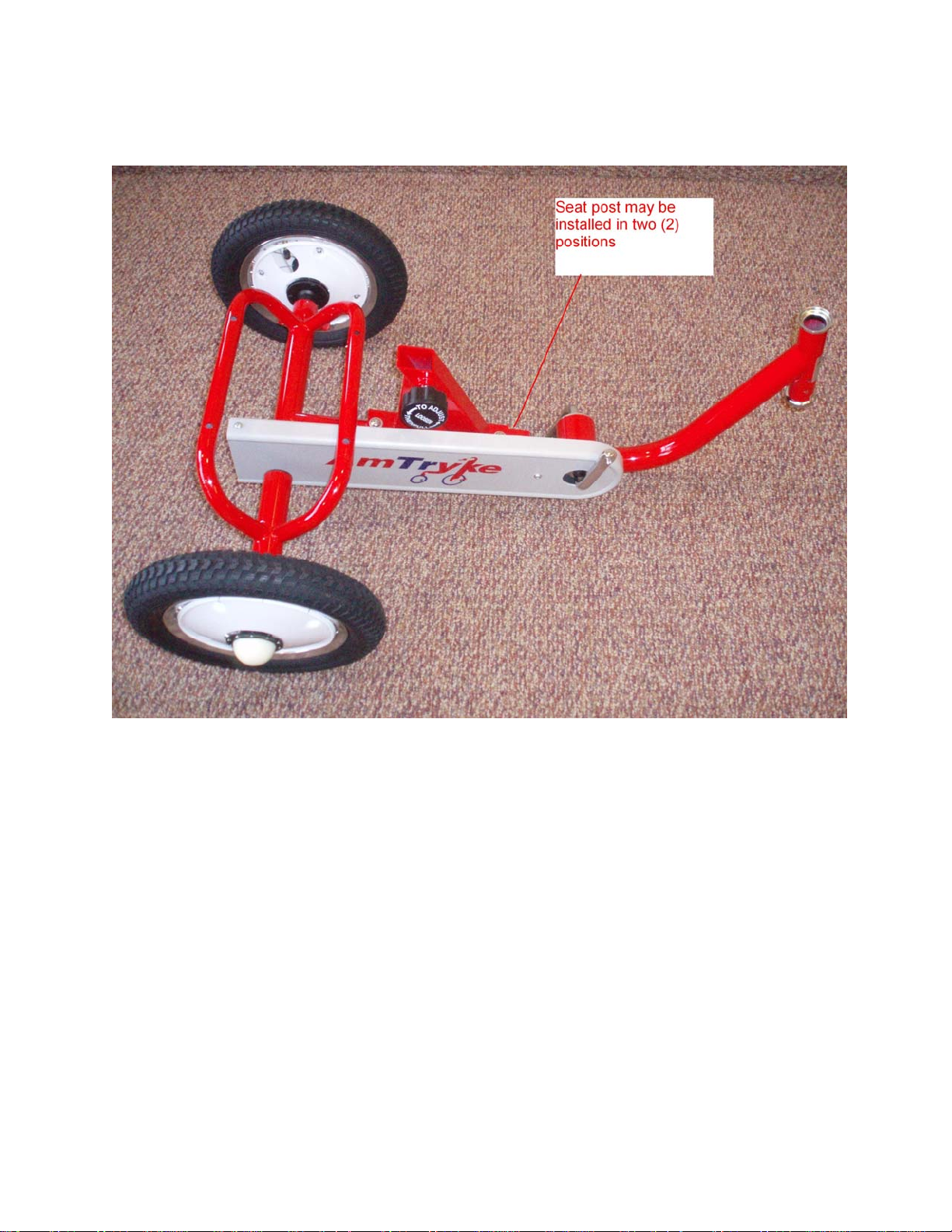
NOTE: THE SEAT POST ASSEMBLY MAY BE MOUNTED IN TWO (2) POSITIONS ON THE
FRAME. THIS ALLOWS DIFFERENT POSITIONING BASED ON THE RIDERS SIZE. THE
SEAT COMES MOUNTED IN THE BACK SET OF HOLES FROM THE FACTORY.
a. Location of the seat post assembly may be adjusted.
b. See above photo for possible seat post positions.
c. Change to desired position with hex wrench (included).
d. Tighten securely seat post to frame before riding.
Revised Date: 11/04/08 Page 2 of 12
Page 3
Assembly Instructions
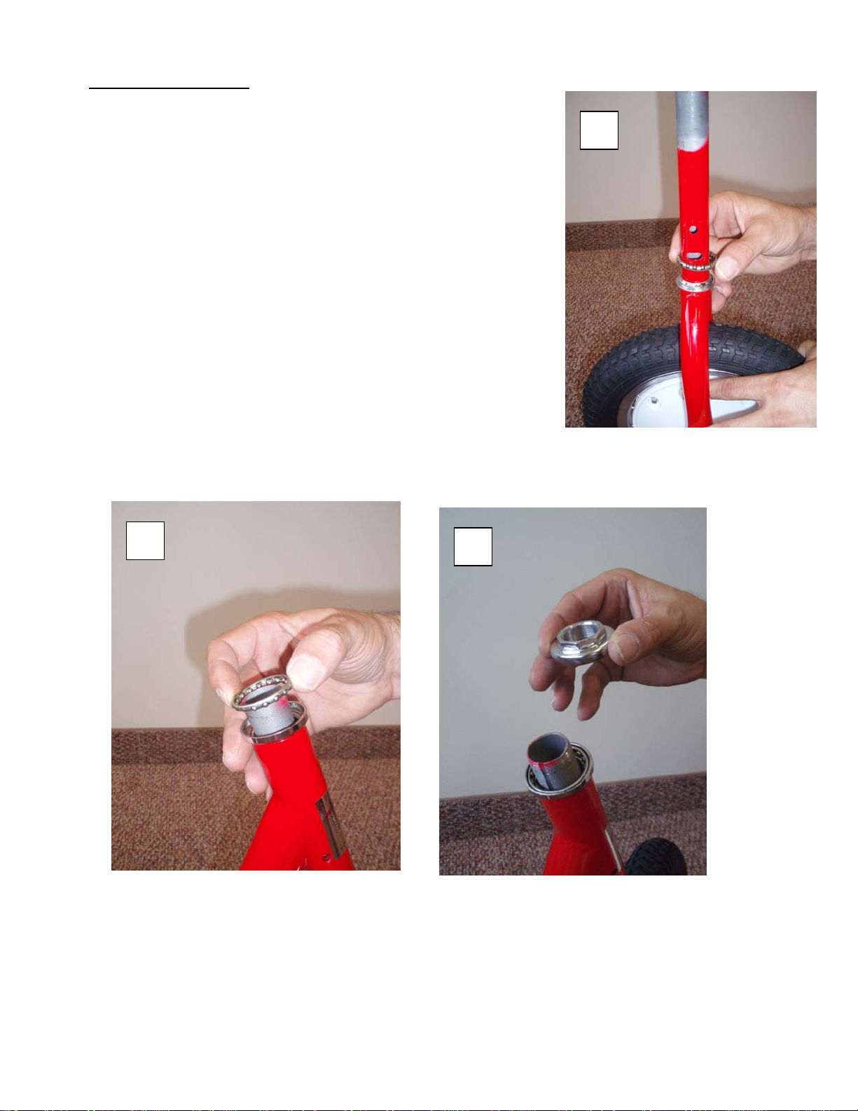
1) FRONT FORK TO MAIN FRAME ASSEMBLY
To mount front fork onto main frame:
a. Slide one of the ball bearing retainers onto the front wheel
fork tube with ball bearings facing up. Then insert the fork
tube into the main frame tube.
b. Slide the second ball bearing retainer onto the top of the
fork tube. The ball bearings face down and seat into the
chrome ring in the main frame.
c. Screw the head cup onto the threaded top of the fork tube.
Tighten this but do not over tighten. The fork assembly
should be snug with no play, but it should allow for easy
turning movement.
d. The lock washer is installed next. Install it into the top of
the fork tube. Be sure the tab in the washer is inserted into
the slot in the fork tube.
e. Finally, install lock nut onto the fork tube. It threads onto
the fork tube. Tighten securely.
B.
C.
A.
Revised Date: 11/04/08 Page 3 of 12
Page 4
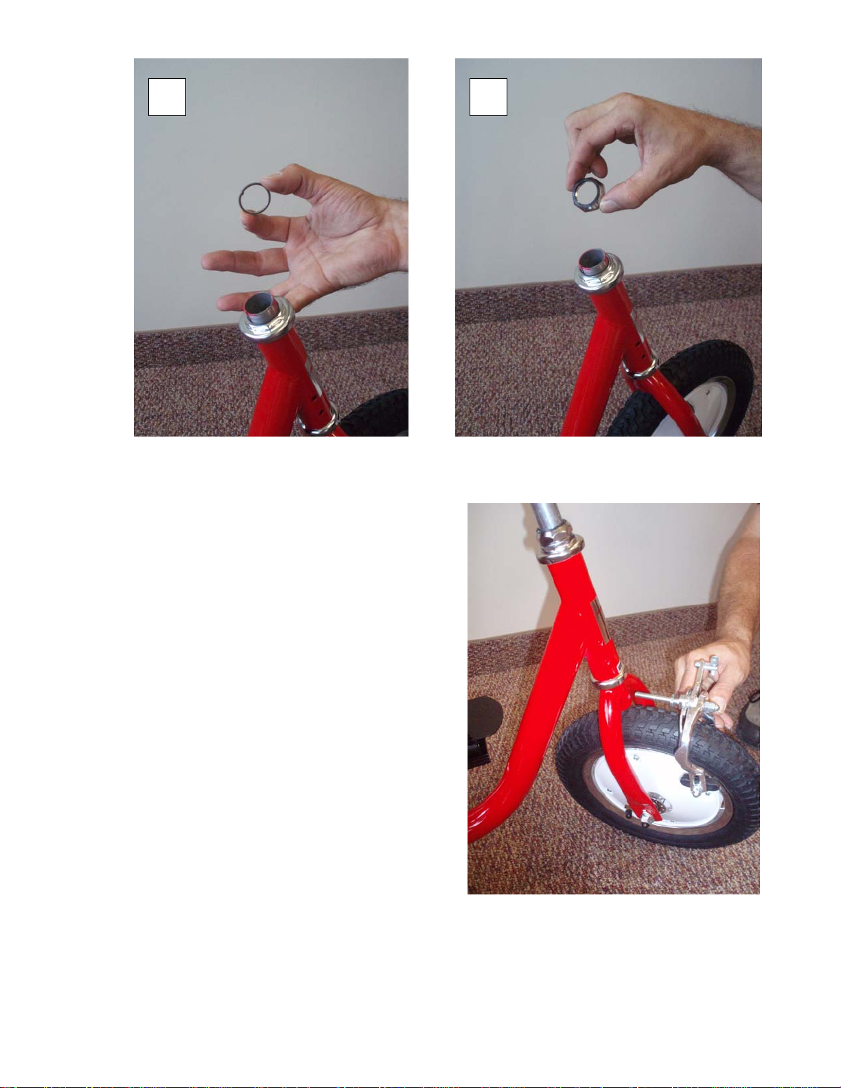
2) FRONT BRAKE ASSEMBLY
a. Front Brake – First take the nut, washer, and one
contoured washer off of the brake. Insert brake bolt
through hole in fork and reinstall counter washer,
washer and nut. Make sure brake assembly is
centered on fork before tightening. Contoured
washers fit on either side of fork. Use 10 mm wrench
to tighten.
D. E.
Revised Date: 11/04/08 Page 4 of 12
Page 5
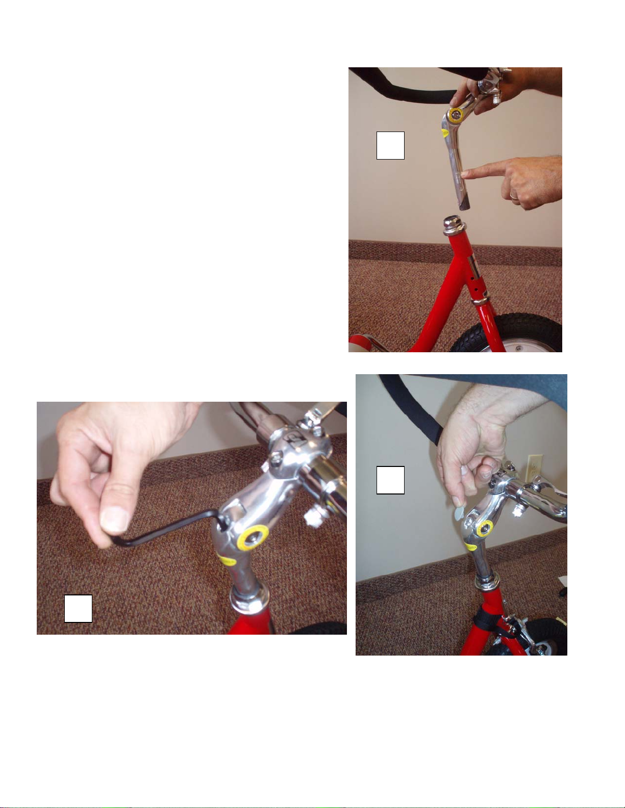
3) HANDLEBAR AND STEM
a) Remove black plastic cap from handle bar stem.
Insert stem of handlebar assembly into fork
head tube. **NOTE: THE STEM MUST BE
INSERTED INTO THE FORK HEAD TUBE
TO AT LEAST THE MINIMUM INSERTION
LINE.
b) Secure stem by tightening stem expander hex
head bolt (located under the gray plastic cover
at top of stem – check in plastic bag for small
gray plastic cover) using a 6mm Allen wrench
(included). Be sure to center stem with the front
wheel.
c) Replace gray plastic cover.
d) Tighten 2 hex head screws at top of stem to
tighten Handlebar clamp.
e) Use quick release locking cam levers to adjust
handle bar position and tighten securely.
A.
C.
B.
Revised Date: 11/04/08 Page 5 of 12
Page 6
E.
D.
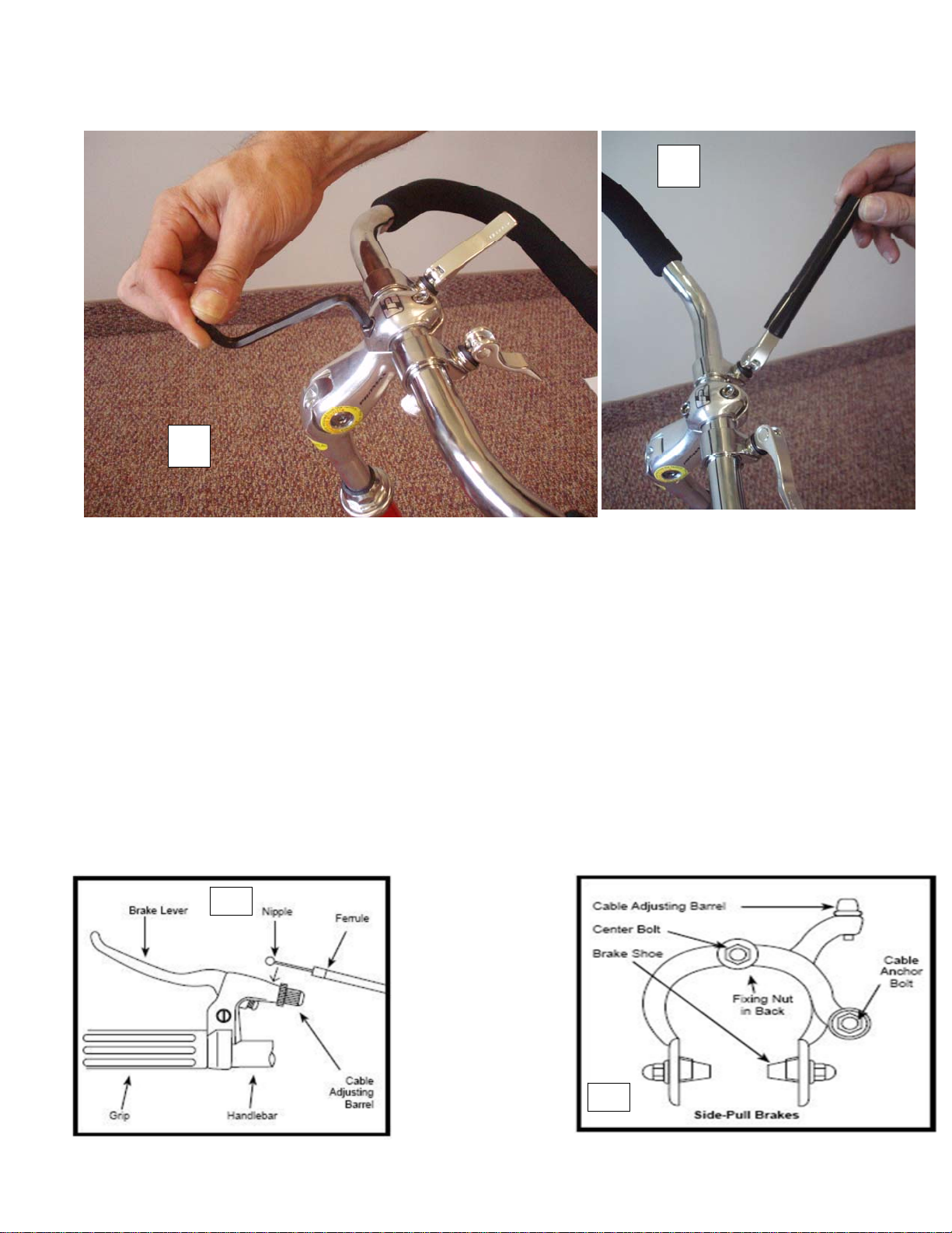
4) BRAKE LEVER INSTALLATION
a) Mount hand brake lever to comfortable position on the handlebars for your rider. Trim foam
grip to allow clearance for desired brake position.
b) Open the brake lever and place the nipple end of the brake cable into the lever, then close the
lever. Secure the ferrule against the lever using the cable adjustment.
c) Loosen the cable anchor nut and thread the brake cable through it. Tighten the nut by hand
until it holds the cable in place. Squeeze the brake arms together against the rim of the wheel.
Loosen the nuts on the brake shoes and turn until the match the angle of the rim. Tighten the
nuts securely. Pull down on the end of the brake cable with pliers, hold taut and securely
tighten the cable anchor nut. Spin the wheel, the brake shoes should not contact the rim at any
point and should be equal distance from the rim on both sides. Mare sure all nuts and bolts are
securely tightened. Test brake levers 20-25 times to take care of any initial cable stretch. Be
sure to tightly secure the brake fixing nut behind the fork.
Revised Date: 11/04/08 Page 6 of 12
Page 7
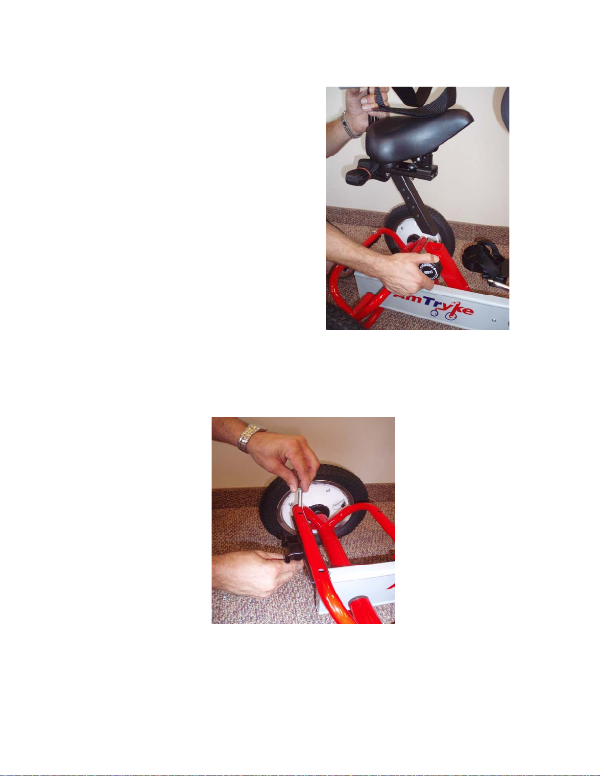
5) SEAT POST FRAME ASSEMBLY
a) Slide seat post assembly into slanted tube on
main frame. Pull back on spring loaded knob
and let pin seat into desired hole on seat post
assembly. NOTE: Seat post knob is never
removed. Simply loosen, pull out on spring
loaded knob, and then tighten once pin is in
desired hole position.
6) BASKET BRACKET ASSEMBLY
a. Mount the black basket bracket onto the rear bar of the frame behind the seat using 1 ¾” bolts
with nuts and washers. The bracket is mounted from the bottom of frame bar. Insert bolt and
washer from top and place washer and nut on end of bolt – tighten.
Revised Date: 11/04/08 Page 7 of 12
Page 8
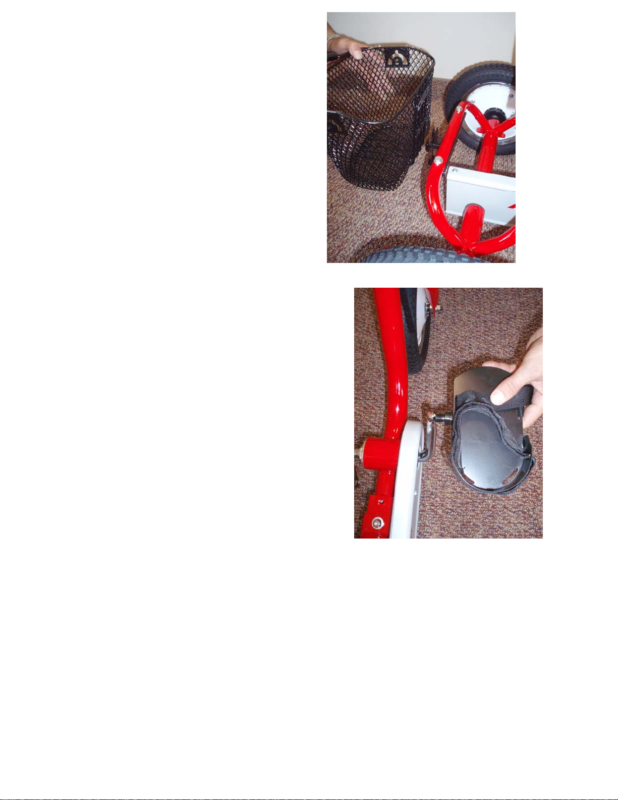
7) BASKET ASSEMBLY
a) Bars at rear of basket mount onto bracket at
back of tryke. Two screws and nuts (black)
can secure basket if rider desires permanent
attachment.
8) PEDALS
NOTE: there is a right and left pedal indicated by an
L or R on the end of each pedal axle.
a. Mount pedals onto crank. Left pedal tightens left.
Right pedal tightens right. Use 15mm wrench to
tighten.
b. **NOTE: BE CAREFUL WHEN THREADING
PEDALS. DO NOT FORCE!! PEDALS THREAD
EASILY WHEN INSTALLED PROPERLY.
Revised Date: 11/04/08 Page 8 of 12
Page 9
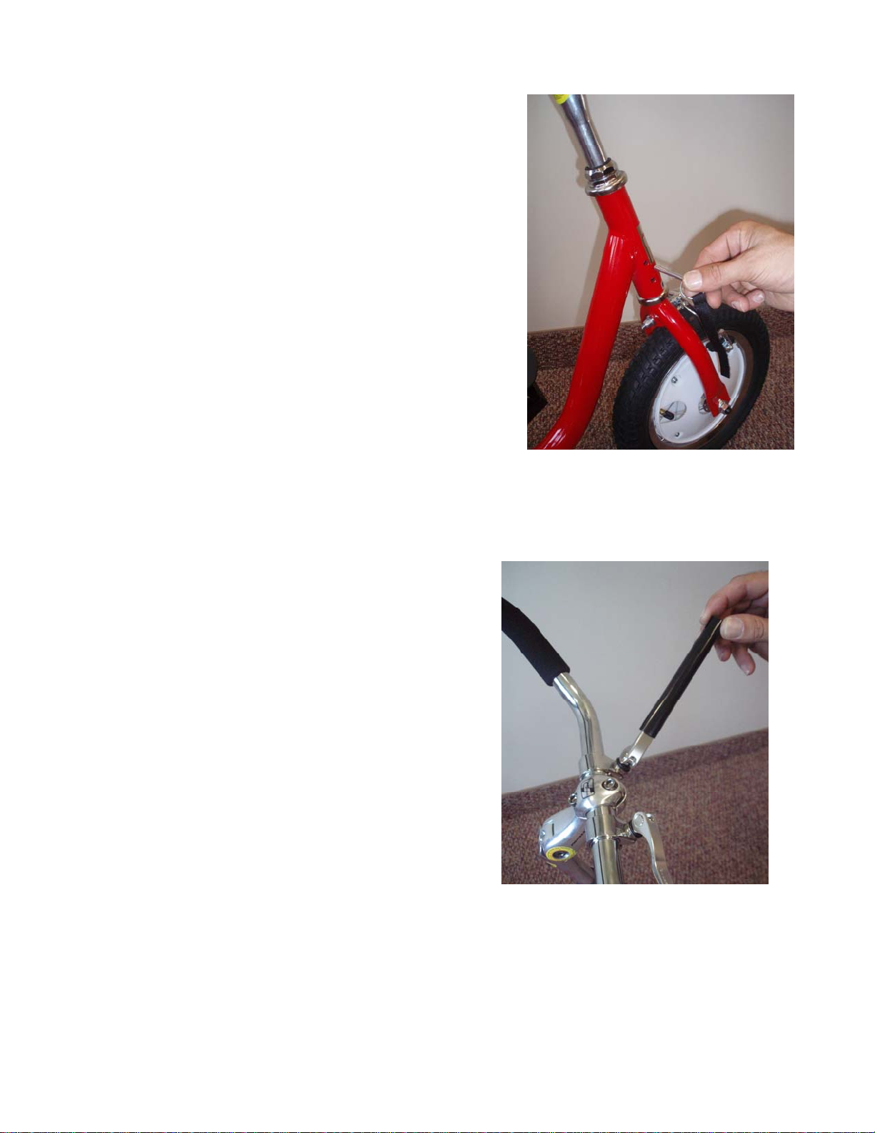
9) STEERING PIN INSTALLATION
a) The steering inserts into the front fork tube from the
side.
b) The top position locks the steering straight. This
allows for easy transfer or if the child needs
assistance with learning to steer properly.
c) The lower position limits the steering to 20 degrees in
either direction. This is very helpful in limiting the
turning radius of the tryke. It keeps a rider from over
steering and adds to safe riding.
d) Install the adhesive hook strip to the frame to keep the
steering pin secure form loss.
10) QUICK RELEASE WRENCH
a) The quick release wrench is included. (black tube
with one end crimped and one end slotted)
b) This is useful for gaining leverage to insure quick
release locking cam levers are tightened securely.
Revised Date: 11/04/08 Page 9 of 12
Page 10
Revised Date: 11/04/08 Page 10 of 12
Page 11

Page 12

 Loading...