

Page 1
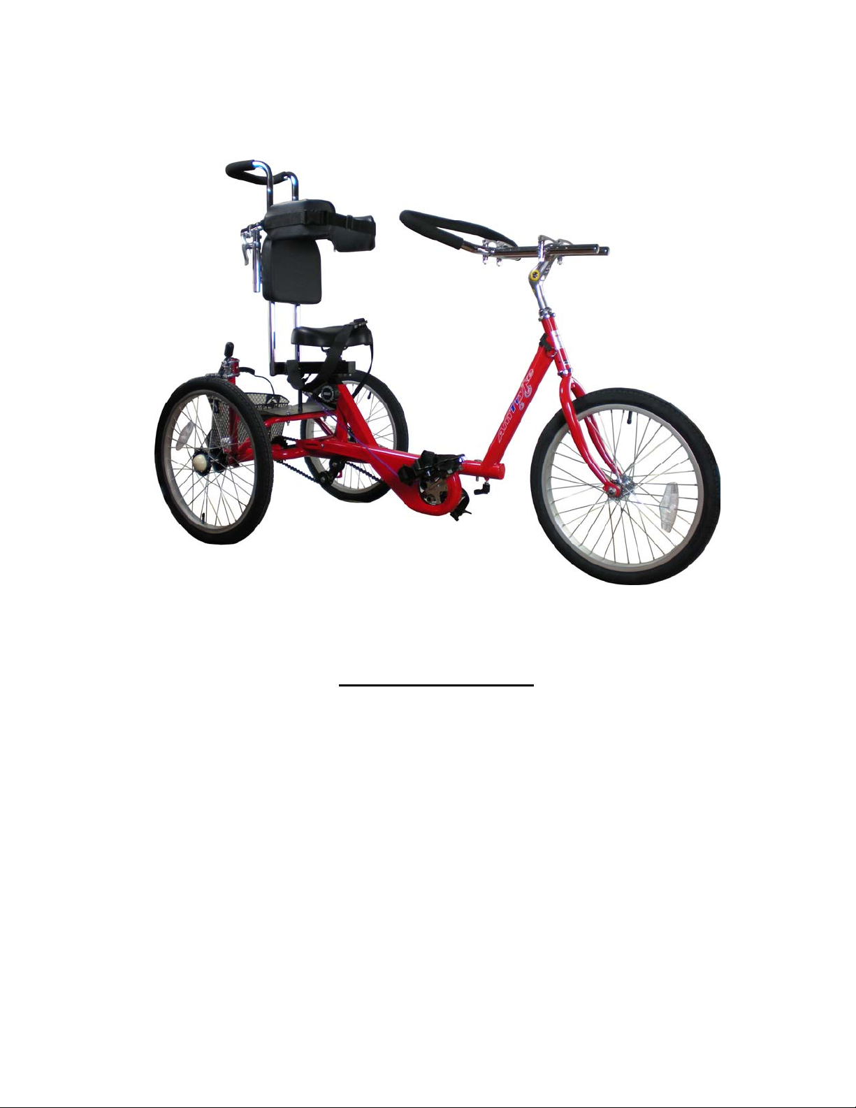
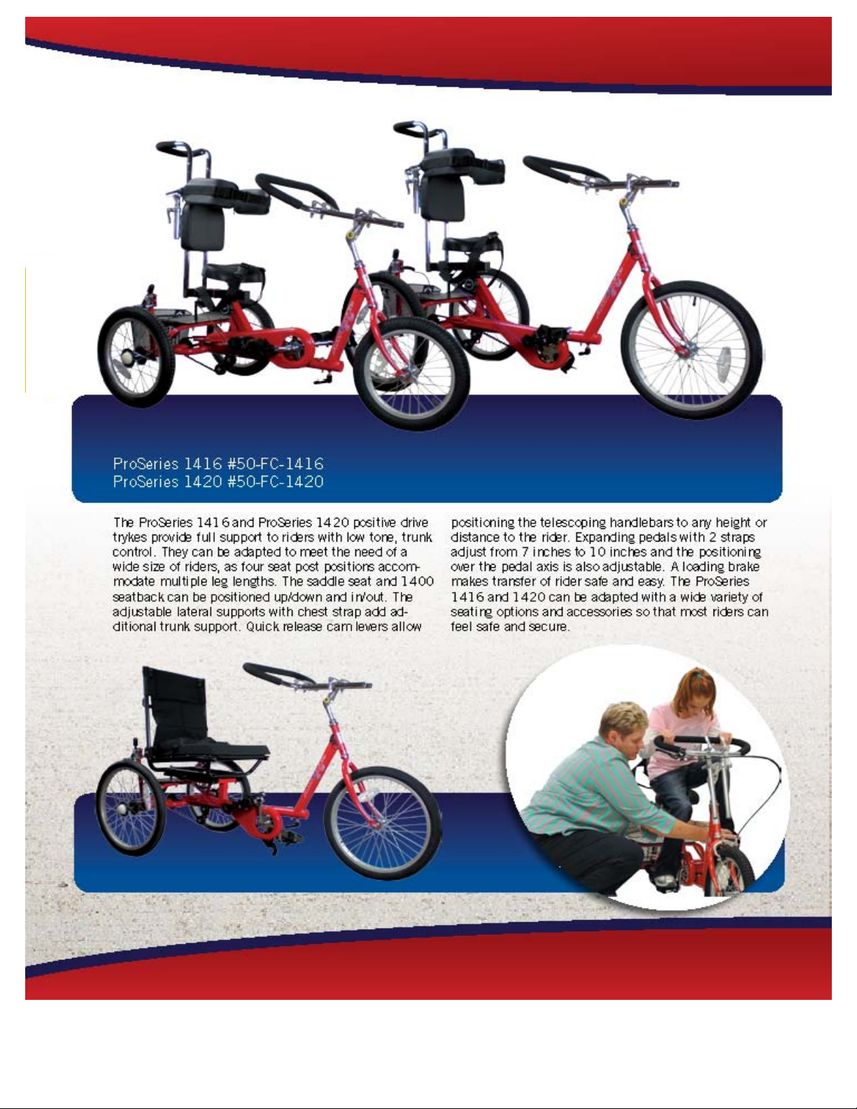
Amtryke® ProSeries Model #1416 50-FC-1416 and
ProSeries Model #1420 50-FC-1420
8 mm Socket or Wrench 10 mm deep well socket or wrench
12 mm Socket and Wrench 13 mm Socket or Wrench
14 mm Socket or Wrench 15 mm Socket or Wrench
7/32 Allen Wrench 5/32 Allen Wrench
Needle Nose Pliers Phillips Head Screwdriver
Utility Knife
Tools Needed for Assembly
Carton Contents
Carefully remove and lay out all parts from the carton so as not to scratch or lose any parts or pieces.
The shipping carton should contain the pictured items on the parts pages.
Revised 11/04/08 Page 1 of 16
Page 2
Pro Series 1416 and 1420
Additional Instructions for Seat Post and Basket
These additional instruction are being provided as a supplement to the normal instructions for assembly
provided for the 1416 and the 1420.
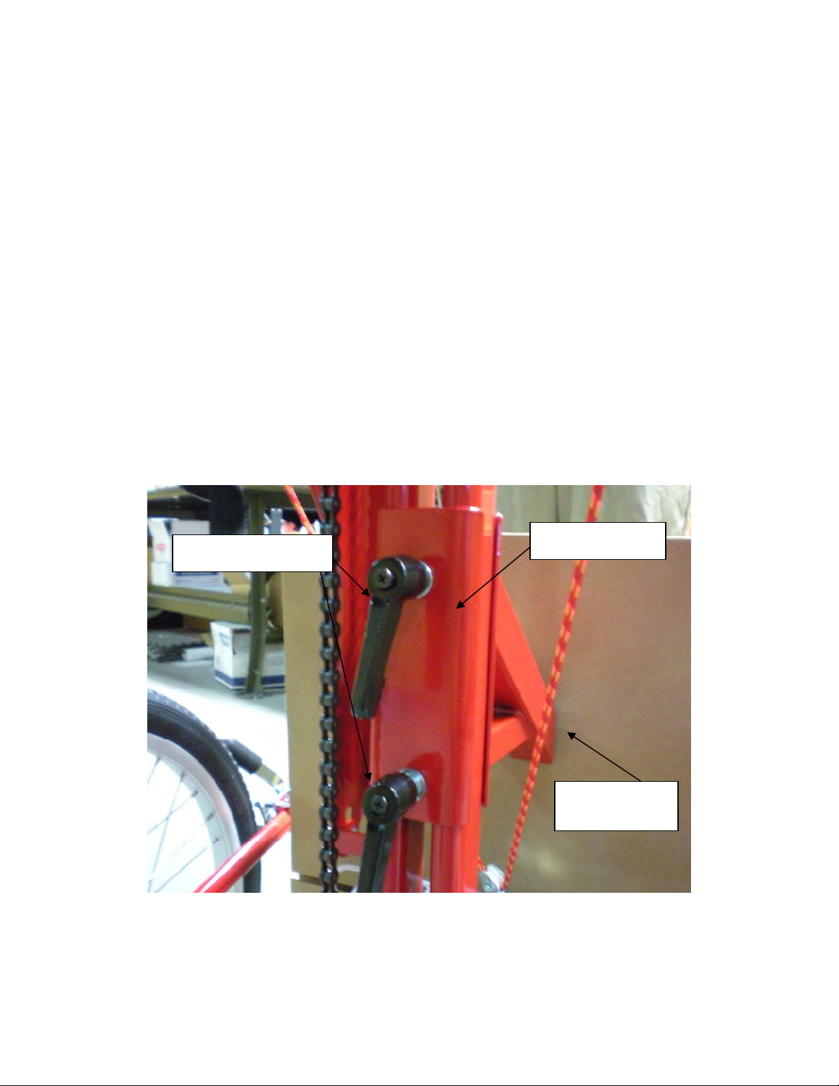
Seat Post Installation
1) Place the red seat post bracket on the frame and from the underside place the plate and install one
securing knob at a time with washer until tight.
Securing Knob
Seat post Plate
Seat post
Bracket
Revise Date: 4/6/2011
Page 3
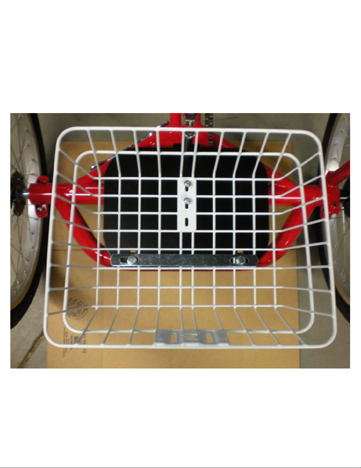
Basket Installation
1) Place basket on black metal plate and align up the slotted holes with the holes in the black metal plate.
2) Insert one Phillips head screw into each hole and turn clockwise to tighten.
3) Place chrome metal brace over basket as shown in photo and use two 12mm bolts and nuts, tighten
securely.
Revise Date: 4/6/2011
Page 4
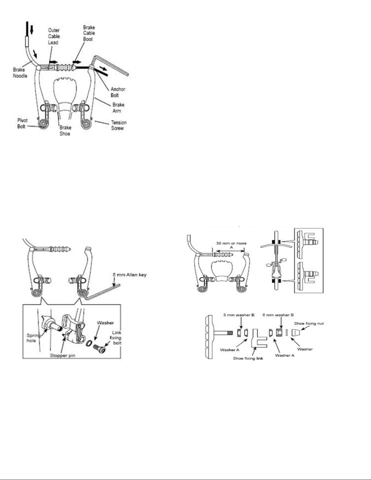
V-Brake
1. If fitted with V-Brakes, insert the brake body
into the center spring hole in the frame mounting
boss, and then secure the brake body to the frame
with the link fixing bolt.
V-Style Brakes
If not already assembled, take the brake noodle from the parts box and
slide the cable through the larger opening. The cable housing will then
seat into the end of the noodle. Slide the cable through the cable lead on
the end of the left brake boot arm; this will cause the noodle to fit into the
lead. Slip the brake cable boot over the cable and position it between both
brake arms. Next loosen the 5mm anchor bolt at the end of the right
brake arm and slide the cable under the retaining washer. Pull the slack
out of the cable making sure a distance of 39mm or more remains
between the end of the lead and the start of the anchor bolt. Once the
cable is secured to the brake arms, engage the brake lever several times,
checking the position of the brake shoes at the rim. The brake shoes
should be 1mm away from the rim when in a relaxed position. When the
brake lever is engaged, the brake shoe should hit the rim flush (never the
tire) with the front brake pad touching the rim slightly before the rear.
This is called “toeing-in” your brake shoe. If this position is not achieved,
adjustments to the brake shoe are required. Loosen the brake shoe
hardware and reposition the brake shoe. It may take several shoe and
cable adjustments before the required position is accomplished.
2. While holding the shoe against the rim, adjust the amount
of shoe protrusion by interchanging the position of the B
washers (i.e. 6 mm and 3 mm) so that dimension A is kept at
39 mm or more.
3. While holding the shoe against the rim,
Revise Date: 8/06/09 14 of 29
tighten the shoe fixing nut.
5. Adjust the balance with the spring tension adjustment
screws.
Page 5
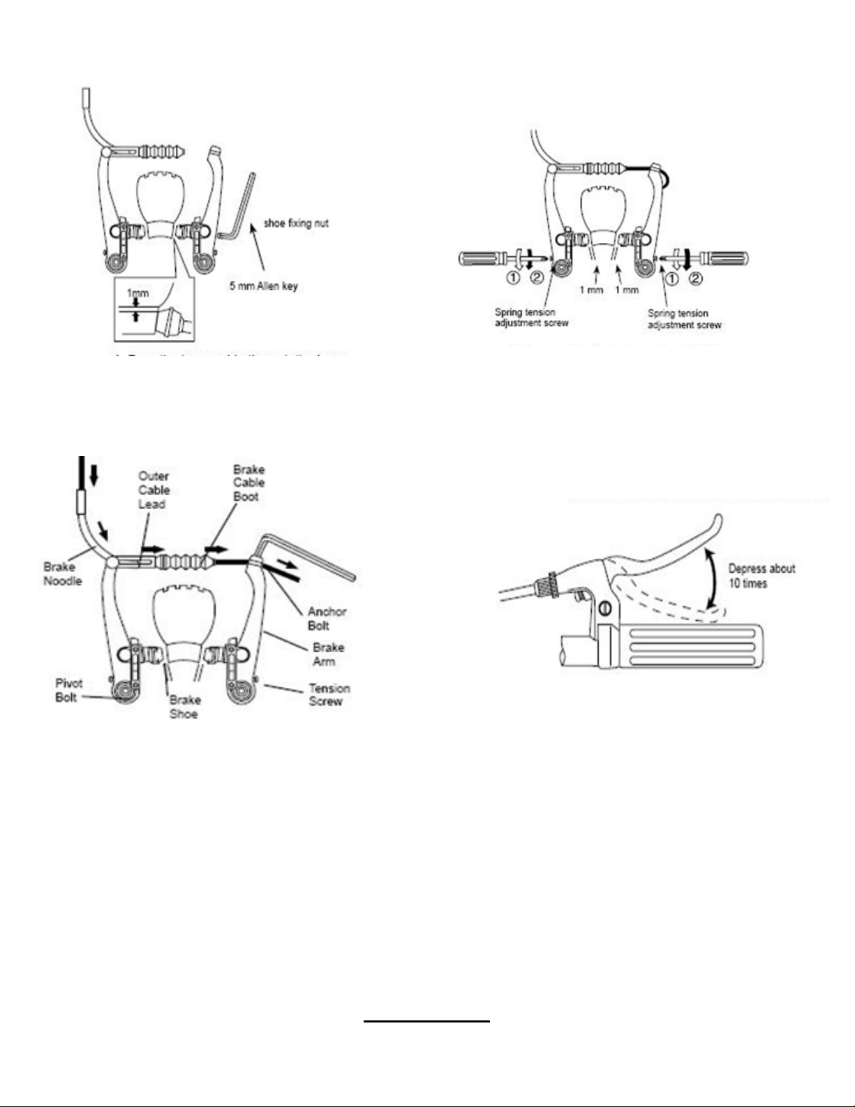
4. Pass the inner cable through the inner cable lead. Set the
cable with the clearance of 1mm between each brake pad
and the rim, tighten the cable fixing bolt.
Cable Retainer
6. Depress the brake lever about 10 times as far as the
grip to check that everything is operating correctly and
that the shoe clearance is correct before using the
brakes.
Revise Date: 8/06/09 15 of 29
Page 6
2) REAR WHEELS ASSEMBLY
a) Inflate tires to proper inflation pressure, 35 psi.
b) The 2 rear wheels are the same (black hubs with 3 holes). The right side hub has three (3) pins
that insert into wheel hub. Install the drive wheel first (right side) , add washer, and tighten the
bolt on the axle, allowing wheel to spin.
c) ** CAUTION: OVER-TIGHTENING WILL DAMAGE THE BEARINGS.
d) Put the idler wheel on the left side. First slip on the spacer, then the wheel, followed by a
washer and the locking nut. Tighten nut until it touches the bearing, do not over tighten.
e) Cover axle nuts with white plastic protectors.
Note: Right wheel (drive wheel) nut should be tighter that left wheel (idler wheel).
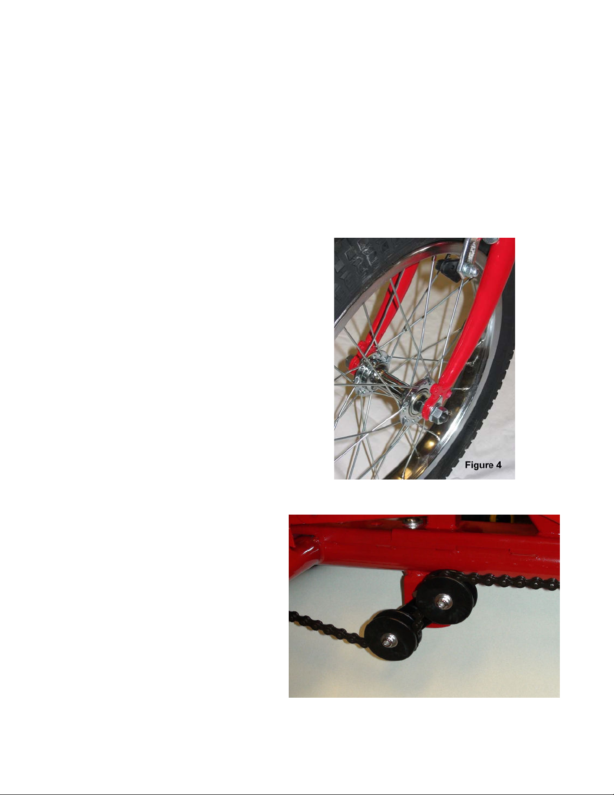
3) FRONT WHEEL ASSEMBLY (Figure 4 )
a. Loosen nuts on both sides of wheel axle.
b. Slide fork onto wheel axle. Note: Safety
washers go on outside of fork.
c. Tooth on safety washers insert into hole on the
fork.
d. Tighten nut and washer securely.
e. Follow same sequence on other side making
sure wheel is centered onto fork while
securing.
4) CHAIN TENSIONER ASSEMBLY
a. No adjustment should be needed to
the chain tensioner assembly.
b. If you decide to change the position
of the front sprocket and foot crank
assembly, you will need to use the
tensioner to adjust the chain.
c. This is accomplished by loosening
the two bolts, turning the chain
tensioner to the desired position, and
re-tightening the bolts securely.
Revised 11/04/08 Page 3 of 16
Page 7
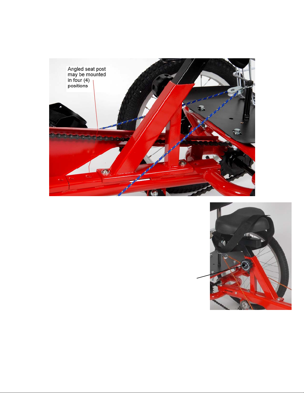
5) SEAT POST FRAME ASSEMBLY
a) The red seat post assembly may be mounted in four (4) positions on the main frame.
b) Choose whichever set of holes will best fit the rider’s size and ability.
c) Make sure the adjustment knob is on the right side (chain side) of the frame. Use the Allen
head bolts, extra thick washers, and tighten with the 6 mm Allen wrench (included).
6) SEAT ASSEMBLY
a. The black seat bracket comes pre-assembled. Use the spring-
loaded knob to adjust the height of the seat post for your rider.
Pull on black spring loaded knob and adjust so the pin pops into
one of the holes in the seat bracket. Once you have selected the
seat height for the rider, the spring loaded knob will click into
place - then hand tighten securely. It is not necessary to remove
the seat post knob – just loosen and pull to release the pin for
adjustments.
Spring loaded knob
Revised 11/04/08 Page 4 of 16
Page 8

b. Mount the saddle seat by inserting the seat clamp onto the seat post. Adjust seat to proper level.
Secure by tightening nuts evenly on both sides of seat clamp using 15 mm wrench (included).
A 9/16” wrench or socket wrench is also suitable here.
Seat Clamp Nuts
7) BASKET PLATFORM ASSEMBLY
a) Mount the black basket platform assembly
onto the rear of the frame behind the seat
using 1 ¾” bolts with nuts and washers.
The flared sides go up.
Revised 11/04/08 Page 5 of 16
Page 9
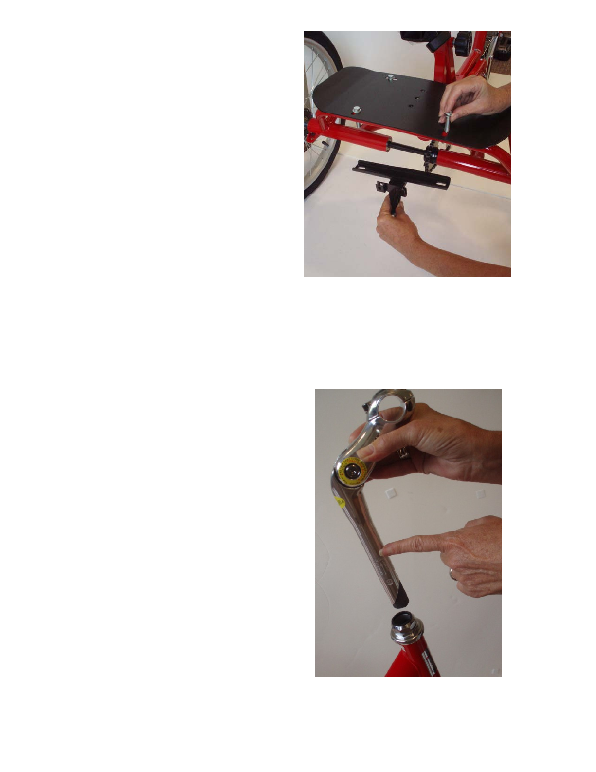
b) The black metal basket bracket mounts
using the same bolts that fasten the
platform to the rear frame. It mounts to
the bottom of the frame with the small
bars facing out.
c) Mount basket into slots in bracket. Use the optional screws if basket is permanent attachment.
8) HANDLEBAR AND STEM
a) Remove black plastic cap from handle bar
stem. Insert stem of handlebar assembly into
fork head tube. **NOTE: THE STEM
MUST BE INSERTED INTO THE FORK
HEAD TUBE TO AT LEAST THE
MINIMUM INSERTION LINE
Revised 11/04/08 Page 6 of 16
Page 10
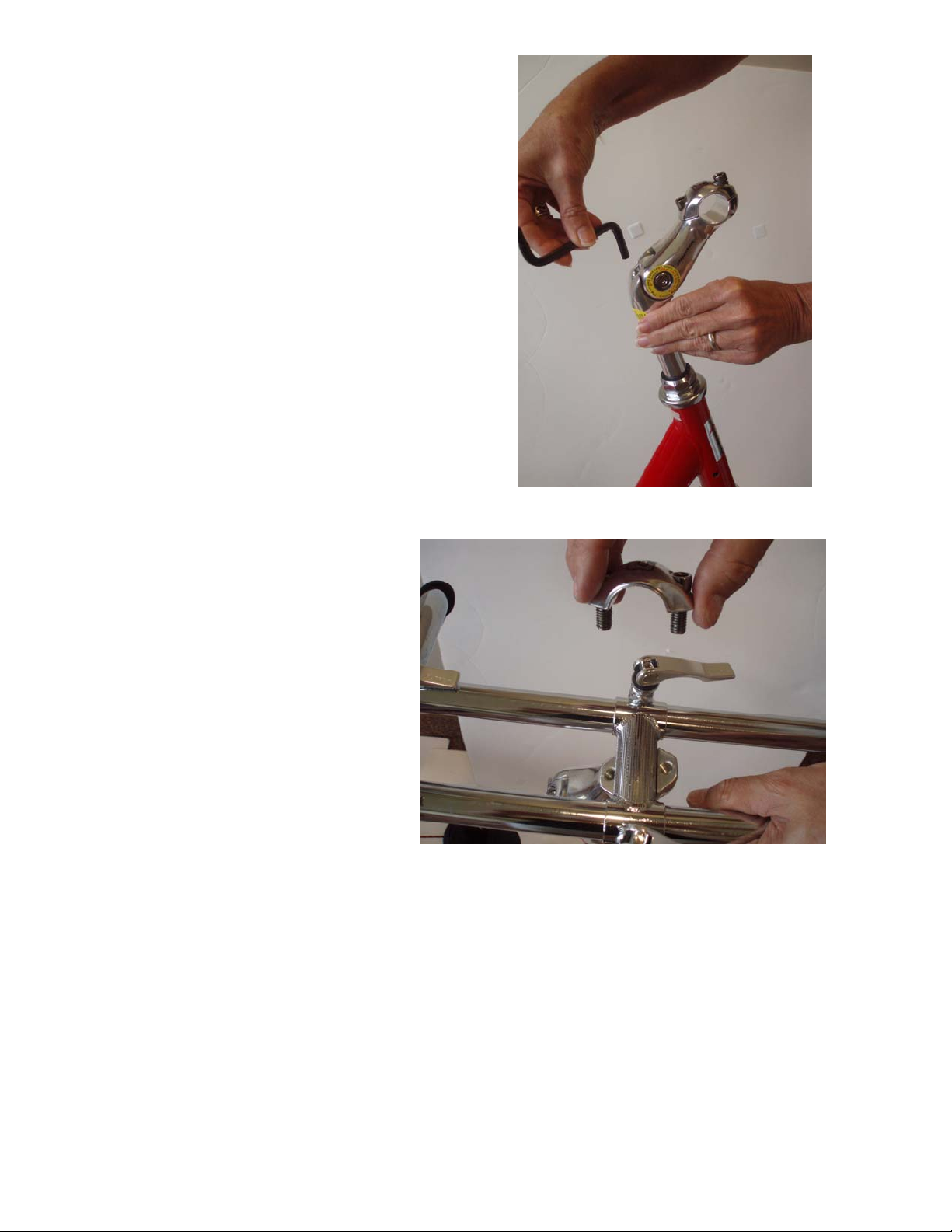
b) Secure stem by tightening stem expander bolt
(located under the gray plastic cover at top of
stem – check in plastic bag for small gray
plastic cap) using a 6mm Allen wrench
(included). Be sure to center stem with the
front wheel. Replace gray plastic cover.
c) Loosen the 2 hex head screws
located on the top of stem and
remove handlebar clamp. Place
the handlebars on the stem and
replace the handlebar clamp.
Revised 11/04/08 Page 7 of 16
Page 11
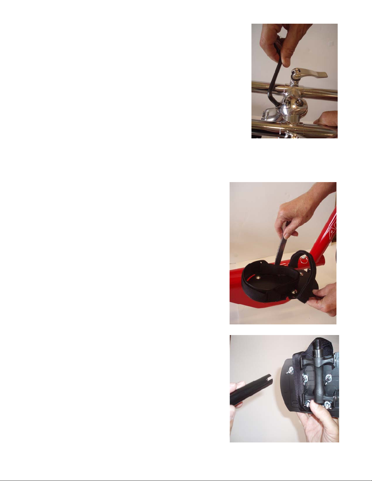
d) Tighten 2 hex head screws at top of stem to tighten Handlebar
clamp.
e) Use quick release levers to adjust handle bar position and
tighten securely.
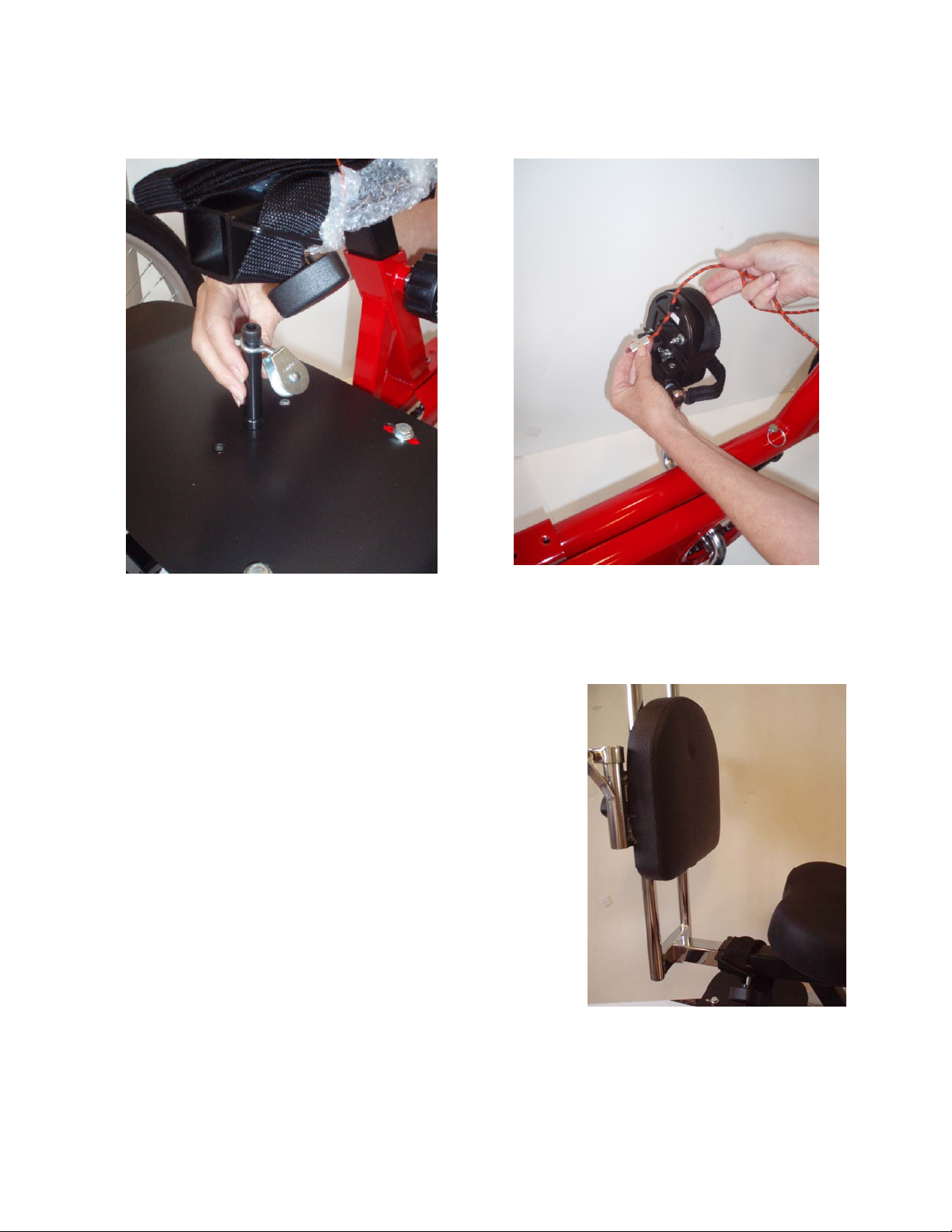
11) PEDALS . NOTE: there is a right and left pedal
indicated by an L or R on the end of each pedal axle.
a) Mount left pedal onto left crank arm. Left pedal
tightens left. (towards the front of the tryke) Mount right pedal
onto right crank arm. Right pedal tightens right.(towards the
front of the tryke). Use 15mm wrench to tighten.
**NOTE: BE CAREFUL WHEN THREADING PEDALS.
DO NOT FORCE!! PEDALS THREAD EASILY WHEN
INSTALLED PROPERLY.
b) Pedals adjust to size. Length can be shortened or
lengthened to fit foot. Position of pedal over axle can also
be adjusted. Use the quick release wrench slotted end to
easily loosen and tighten wing nuts.
Revised 11/04/08 Page 8 of 16
Page 12
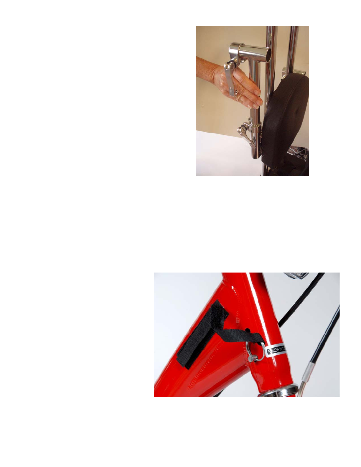
12 PEDAL LEVELER ASSEMBLY
a) Screw pulley block assembly into hole in black basket platform. Thread cord through left side
pedal from inside, then through the pulley on pulley block assembly and into rear of right
pedal.
b) Pull snug until pedals remain level and crimp copper stop at appropriate spot on cord.
(Alternately, tie knot in cord to appropriate length.)
13 SEAT BACK SUPPORT ASSEMBLY
a) Slide the chrome seat back support assembly onto the
black seat support bracket. Tighten with the black knob
that thread into bottom corner of the bracket.
b) Make sure the padded seat back can slide up and down
the assembly. Position it where desired and tighten with
the two knobs on the back.
Revised 11/04/08 Page 9 of 16
Page 13
c) Mount brackets for the Lateral supports if
desired.
d) Lateral supports slide into brackets and tighten
with cam levers. NOTE: LATERAL
SUPPORTS ARE GROOVED ON BOTTOM
AND SLIDE INTO SUPPORTS.
14 SEAT BELT ASSEMBLY
a) Seat belt or lap strap is pre-installed. Make sure hook fastener faces away from rider.
15 WHEEL REFLECTORS
a) Mount one reflector in each wheel, using plastic nuts to secure reflector to spoke of wheel.
16 STEERING PIN INSTALLATION
a) The steering inserts into the
front fork tube from the side.
b) The top position locks the
steering straight ahead. This
allows for easy transfer or if
the child needs assistance with
learning to steer properly.
c) The lower position limits the
steering to 20 degrees in either
direction. This is very helpful
in limiting the turning radius of
the tryke. It keeps a rider from
over steering and adds to safe
riding.
d) Install the adhesive hook strip
to the frame to keep the
steering pin secure form loss.
Revised 11/04/08 Page 10 of 16
Page 14
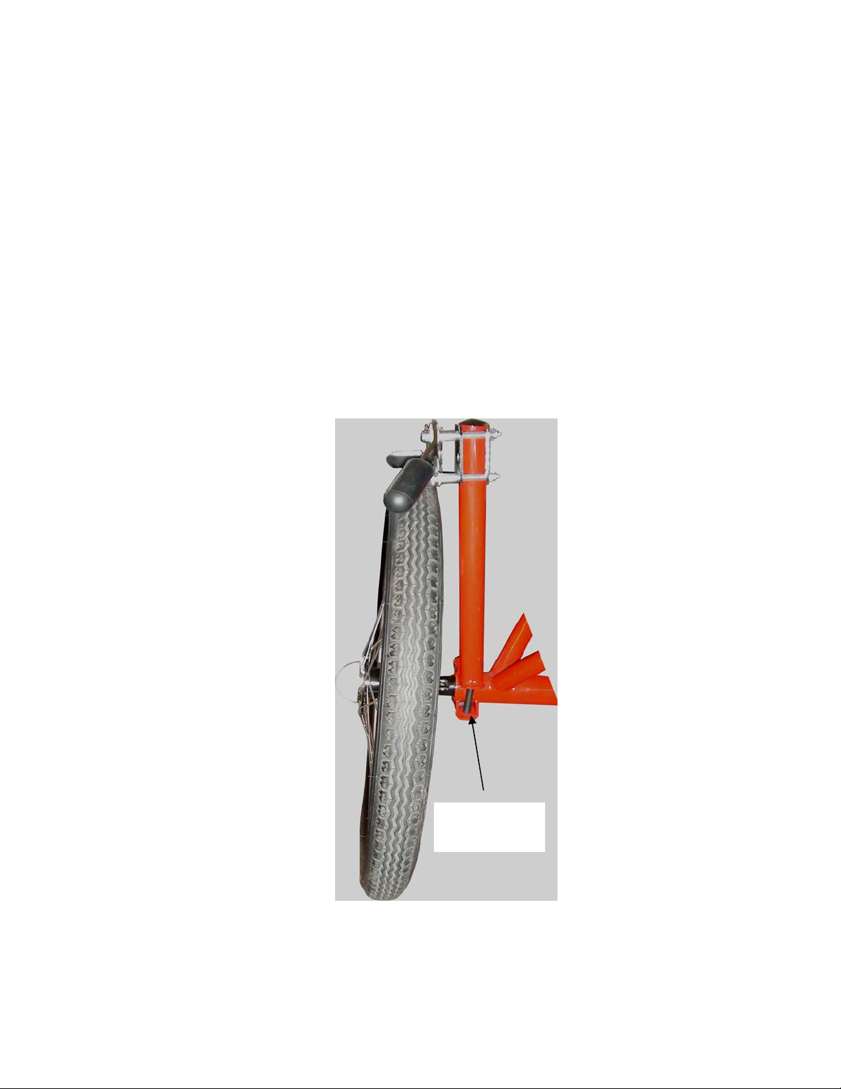
Installation Instructions for the safety Loading Brake
1) Remove the two Allen bolts from the loading brake extension tube.
2) Place the loading brake extension tube over the right rear axle so the handle is pointing towards
the front of the AmTryke, making sure the handle is in the down position and over the tire.
3) Install the two Allen bolts up through the attached bracket on the right rear axle and then turn
them clockwise into the loading brake extension tube. NOTE: the tube angles slightly outward
to position the brake over the tire be sure the foot of the bracket is fully on top of the red axle
tube.
4) Use the double ended Allen wrench provided with your AmTryke to tighten up the two Allen
head screws from the bottom.
Allen head
screws
Revised 11/04/08 Page 11 of 16
Page 15
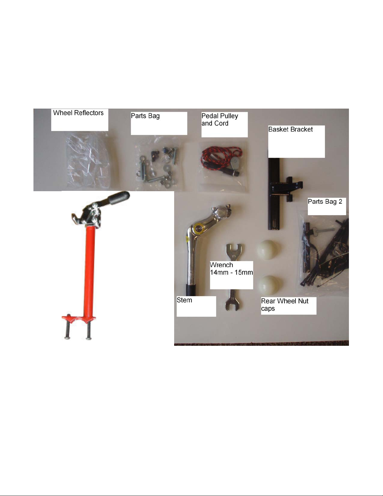
Parts Box
Load Lock/Bracket
Assembly
Revised 11/04/08 Page 12 of 16
Page 16
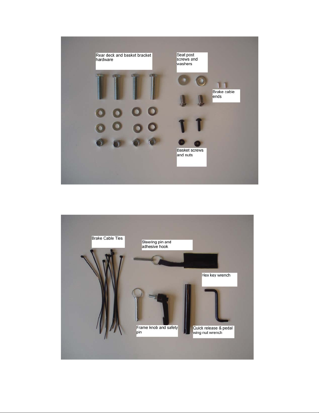
Parts Bag
Parts Bag 2
Revised 11/04/08 Page 13 of 16
Page 17
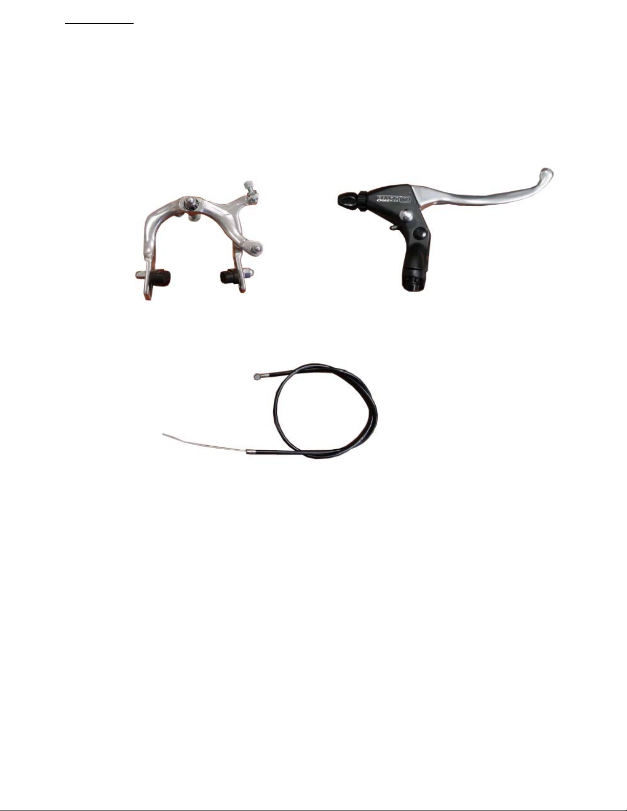
AmTryke LLC.
Optional Hand Brake Components
Part# 30-24-0010
Front Brake Caliper
Locking Brake Lever
Front Brake Cable
National AMBUCS, Inc maintains a warehouse and ships product from High Point, North Carolina. Due to continual
product improvement, AmTryke, LLC reserves the right from time to time to make reasonable substitutions without prior
notice. Prices are subject to change without notice.
Our goal is to provide prompt and efficient service. We try to maintain ample inventory but unusual demand will
sometimes deplete our stock of an item. If due to unusual demand, our inventory of an item is depleted and the item is
backordered, allow six to eight weeks for delivery. You will be notified if an item is delayed or discontinued.
Terms
Individuals may order by using Visa, Mastercard, American Express, check, money order, or may be billed to AMBUCS™
chapter, district or region if authorized.
Revised 11/04/08 Page 14 of 16
Page 18

Shipping
Orders are shipped by USPS, Fed Ex or UPS. Rush orders are sent at your request, and you, or your chapter, district or
region is billed for rush charges and handling. Shipping and handling charges are added to all orders. Please contact us for
shipping items outside Continental U.S.
Fed Ex or UPS:
The guarantee does not apply to shipments that are delayed due to causes beyond UPS or Fed Ex control, including but not
limited to, the following:
1. The act, default or omission of the Shipper, Consignee or any other party claiming an interest in the shipment,
including delivery instructions from the Shipper or Consignee with which we complied;
2. The nature of the shipment, defect, or inherent vice of the product;
3. Failure of the Shipper or Consignee to observe any term contained in these Air Freight Terms, including but not
limited to improper or insufficient packaging, securing, addressing or marking of any shipment, including
omission of, or provision of, an incorrect Consignee address or ZIP code on the Air Waybill, providing
insufficient information, or the Shipper's failure to follow any term related to shipments that are not acceptable for
transport.
4. Acts of God, weather conditions
public authorities acting with actual or apparent authority, acts or omissions of customs officials or similar
authorities, the application of security regulations imposed by the government or otherwise applicable to the
shipment, authority of law, quarantine, riots, strikes or other labor disputes or disturbances, civil commotions or
hazards incident to a state of war, local or national disruptions in ground or air transportation networks or systems
due to events beyond our control, disruption or failure of communication and information systems, disruption or
failure of utilities, or other circumstances beyond our control (hereinafter referred to collectively as "Force
Majeure Events").
5. Compliance with laws, government regulations, orders or requirements, or any cause beyond our control.
, environmental or hazardous goods incidents, perils of the air, public enemies,
You can also mail your order directly to us. The correct USPS address is:
Revised 11/04/08 Page 15 of 16
Page 19
Revised 11/04/08 Page 16 of 16
 Loading...