

Amtrol WX-405, WX-402, WX-406, WX-407, WX-421 Sizing Instructions
...
5.
5.
5.
4.
6.
9.
6.
)
SIZING INSTRUCTIONS
1400 Division Road, West Warwick, RI 02893 T: 401.884.6300 F: 401.885.2567 www.amtrol.com
Series 420 & 447
This handbook will discuss the basic sizing used
for our larger Well-X-Trol
440, and 450 series. This allows you to use the Well-
®
X-Trol
“principle of separation of air and water” on
larger jobs that are beyond the typical residential
range.
The Well-X-Trol
®
models we’ll be working with in
Pressure Switch
®
s such as WX-400, 420,
this handbook are listed in Table 1.
The design features of these larger models allow
us to apply them more creatively than the smaller
®
residential models found in the Well-X-Trol
100,
200, and 250 series.
The Larger Well-X-Trol
®
s are Designed and Built
for Maximum Acceptance on Each Operating
Cycle
®
In the smaller residential Well-X-Trol
s, the design
is for basic intermittent use and for the usually
found in residential applications. Standard pressure
ranges of (20) PSIG (between pump cut-in and
pump cut-out) are used.
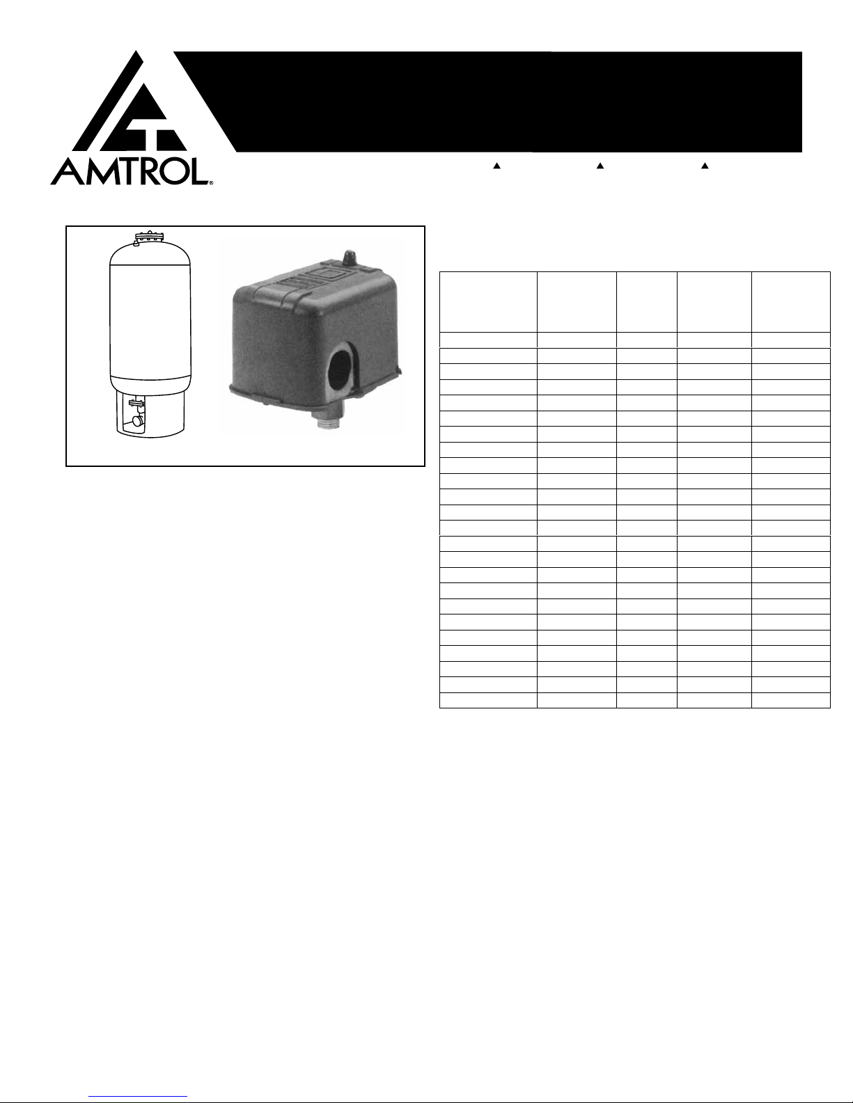
WELL-X-TROL
®
POTABLE WATER WELL TANK
Table 1.
WX Model No.
NON-CODE
(NON-ASME)
WX-401 WX-401-C 17.5 11.2
WX–402 WX–402-C 25 11.2
WX-403 WX-403-C 34 11.2
WX-404 WX-404-C 68 34 .50
WX-405 WX-405-C 90 34 .39
WX-406 WX-406-C 1103
WX-407 WX-407-C 1324
WX-421
WX-422
WX-423
WX-424
WX-426
WX-427
WX-447 WX-447-C 53 34 .65
WX-448 WX-448-C 80 52 .65
WX-449 WX-449-C 1066
WX-450 WX-450-C 1328
WX-451 WX-451-C 158102 .65
WX-452 WX-452-C 211136 .65
WX-453 WX-453-C 264170 .65
WX-454 WX-454-C 317205 .65
WX-455 WX-455-C 370239 .65
WX-456 WX-456-C 422273 .65
WX-457 WX-457-C 528341 .65
Based on 30 PS IG pre-charge (P
WX Model
No.
CODE
(ASM E)
Not avai lable
Not avai lable
Not avai lable
Not avai lable
Not avai lable
Not avai lable
Total
Volume
(Gallo ns)
158103 .65
211137 .65
264172 .65
317206 .65
422274 .65
528343 .65
Maximum
Acce ptance
Volume
(Gallo ns)
Maximum
Acce ptance
Factor
(MAF )
65
45
33
31
35
65
65
In these applications, full use of the maximum
acceptance volume of the Well-X-Trol
required to meet job conditions.
®
is rarely
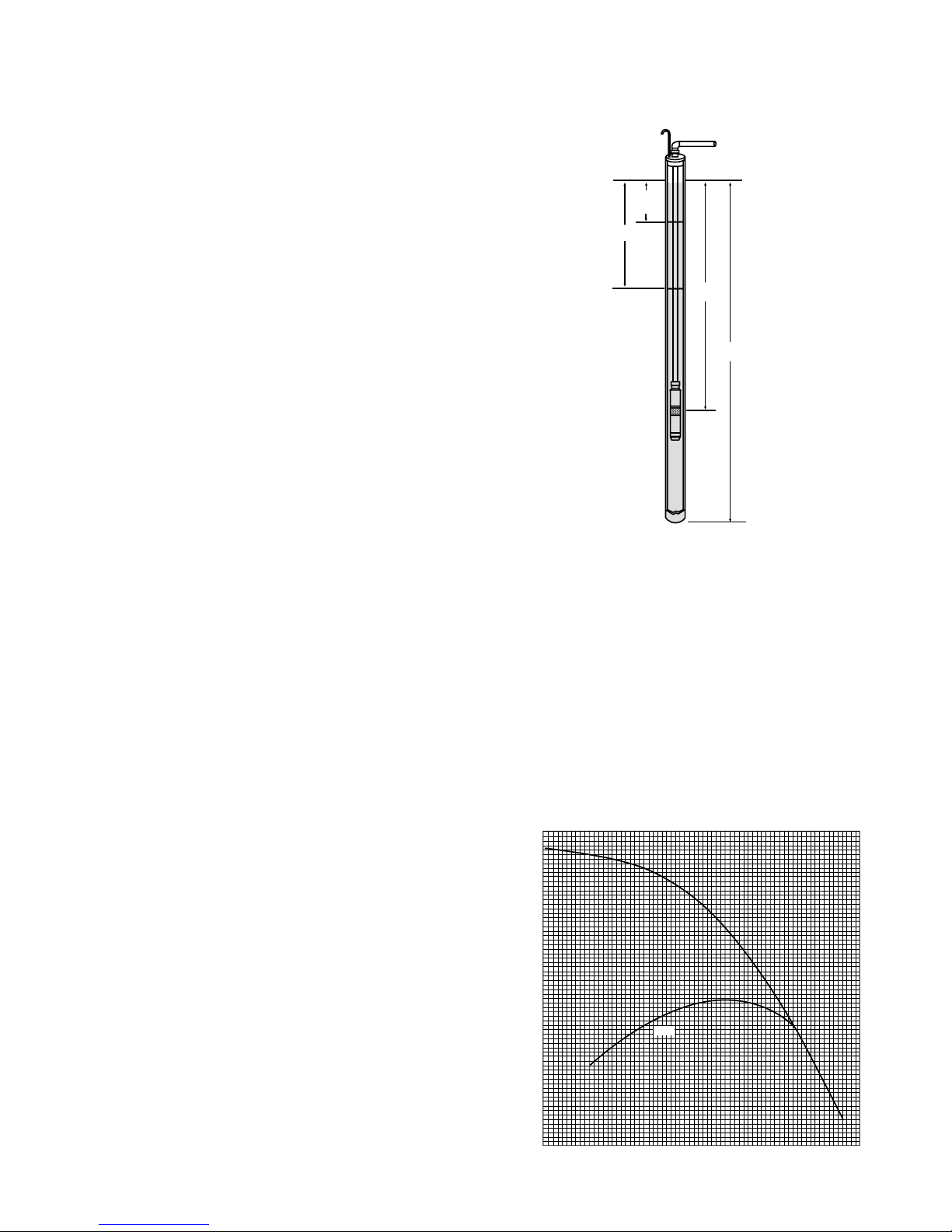
Utilizing the Maximum Capacity of Full
GROUND LEVEL
STATIC
WATER
LEVEL
PUMPING LEVEL
OR LIFT
PUMP
DEPTH
WELL
DEPTH
240 FT.
(In example)
36"
84"
WX-423
1489 LBS.
275 GALS.
TOTAL VOLUME
48"
AIR COMPRESSOR
900 GALLON
GALVANIZED TANK
168"
10,000 LBS. (WITH WATER)
®
Acceptance Well-X-Trol
s Series 400,
420, 440 and 450
When used with conventional pressure ranges,
these Well-X-Trol models use only a fraction of
their maximum capacity.
For Example:
Step One – Determine the Best Operating
Pressure Range – Pump Cut-In (P2) to
Pump Cut-Out (P3):
A WX-423 with a total volume of (275)
gallons will accept the following:
at 30/50 – (85) gallons or 30.9%
at 40/60 – (74) gallons or 26.7%
By using the maximum acceptance of series 420
and 450 Well-X-Trol
cumbersome galvanized tanks.
®
, you can replace very large,
Let’s Compare:
A 900 gallon galvanized tank is (48″) in diameter;
(168″) long, and weighs approximately (10,000)
pounds when filled with water.
Aside from initial cost, the cost of rigging and handling
a tank of that size; (providing adequate support and
the cost of space required) significantly adds to the
overall installation cost.
Requires Air Control
Since at the higher pressures, the galvanized
tank will waterlog at an accelerated rate, some
provision must be made to maintain the required air
cushion. This means the cost of an air compressor
or other means of recharging must be added to the
installation.
On the Other Hand
The first thing we must do in sizing the bladder is to
determine the best pressure range that will achieve
maximum acceptance.
. We can be accurate by letting the pump tell us at
which maximum range it will operate best.
If we look at the pump curve for the pump which is
to be installed…we can easily determine the pump
cut-in pressure (P
) and pump cut-out pressure (P3)
2
that will give us the widest range.
The WX-423 has a total volume of only (275)
gallons; is only (36″) in diameter; and (84″) high.
When filled with water (to the 65% maximum
acceptance) it only weighs (1489) pounds.
It can be easily handled by two men, requires no
support structures and occupies a fraction of the
space of the galvanized tank. Since the Well-X-
Trol
external air compressors or control devices.
If we can use the maximum acceptance of the 420
®
’s air cushion is sealed-in, there is no need for
and 450 Series Well-X-Trol
larger jobs…with large pumps, without paying the
®
, we can service much
penalty of higher installation and maintenance costs.
-2-
700
600
500
400
300
TOTAL HEAD IN FEET
200
100
0
80
60
EFF.
40
EFFICIENCY %
20
20 40 60 80 100 120 140
CAPACITY IN GPM

For example, if we look at a typical pump curve for
a (15) HP – (85) GPM submersible pump – we can
select a pump cut-in and cut-out point on the curve
which will provide optimum pump operation.
The pump curve shows pump performance as
(0)
its pressure rises from cut-off (
head in test) to
maximum head in feet.
On this curve, for a (15) Hp (85) GPM pump we can
see that at approximately (100) feet the pump stops
pumping and will pump up to (660) feet of head.
What we want to determine is at which point on the
curve do we want to have the pump cut-in, and at
which point on the curve do we want it to cut-out.
The pump operates in its best efficiency range at
the mid-range of the curve.
We must select a minimum pressure at the Well-
®
X-Trol
location that will insure enough pressure
to keep water flow under pressure at the top of the
system…overcoming both the static height and the
resistance to flow through the piping.
®
We’ll do this by pre-charging the Well-X-Trol
a pressure (P
required at the Well-X-Trol
we’ll select a pump cut-in pressure (P
) equal to the minimum pressure
1
®
location. In addition,
) which is
2
to
at the same pressure to start the pump whenever
system pressure drops to this point.
We’ll assume that a minimum system pressure
®
at the Well-X-Trol
location of (30) PSIG. This
pressure will be adequate to insure system
pressurization to overcome elevation and friction
loss and provide adequate pressure at the fixture.
The cut-in point can’t be too low on the curve, as this
would cause inefficient operation. We should choose
a point just before the curve drops off rapidly…and
at a point still within the best efficiency range (60% to
80%).
The pump curve for the pump selected indicates the
total pressure range of the pump or its dynamic head
measured in feet of head.
The pump must have enough head, or pressure
differential to:
Bring water from the level of the well to the
well head at the surface of the ground.
Provide head capacity to pressurize system
piping to overcome elevation (static height)
and friction (friction loss) and deliver required
pressure.
®
Since the Well-X-Trol
will control the pump
operation throughout system pressurization, we
must select our pump cut-in pressure and pump cutout pressure.
For example:
To find this pump cut-in point on the pump curve,
we’ll have to convert (30) PSIG to feet of head.
To convert PSIG to feet of head, we must multiply
PSIG by (2.31).
30 PSIG x 2.31 = 69.3 or 70 feet of head
To locate this point on the pump curve, we must
add 70 feet of head…the pump head required to
pressurize the system to 30 PSIG…to the feet of
head required to lift the water to the surface:
Minimum System Pressure = 70 Ft. of Head
Plus Lift = 240 Ft. of Head
* Pump cut-in point on curve = 310 Ft. of Head
We have selected the point on the curve which will
be the pump cut-in setting (P
) of 30 PSIG on the
2
pump switch, and we will pre-charge the Well-X-
®
to 30 PSIG (P1).
Trol
Now we will select the maximum pump cut-out point
on the curve which will allow the widest possible
pressure range without impairing pump performance
and efficiency.
In a well with water level (240) feet down in the well,
system pressurization by pump will be shown on the
pump curve at some point above the intersection of
the line indicating (240) feet of head.
In other words, at (240) feet of head we can assume
that the pump will have brought water from the
pumping level of the well to the surface and pressure
in the system piping will be (0) PSIG.
We now must select a pressure range (min. to
max.) to establish pressurized delivery of water to
the system and that we overcome elevation (static
height) and friction loss of the piping.
We will do this by moving up the curve to find a
point that:
Is just before the curve begins to “flatten” out
And is still within the upper limits of best
efficiency range of the pump
In this example, that point would be at the intersection
on the curve of the horizontal line indicating (410) or
(420) feet of head… let’s say (420) feet.
This is the point on the curve which will be the
maximum pump cut-out for this particular pump.
-3-
 Loading...