

Page 1
INSTALLATION, OPERATION & MAINTENANCE INSTRUCTIONS
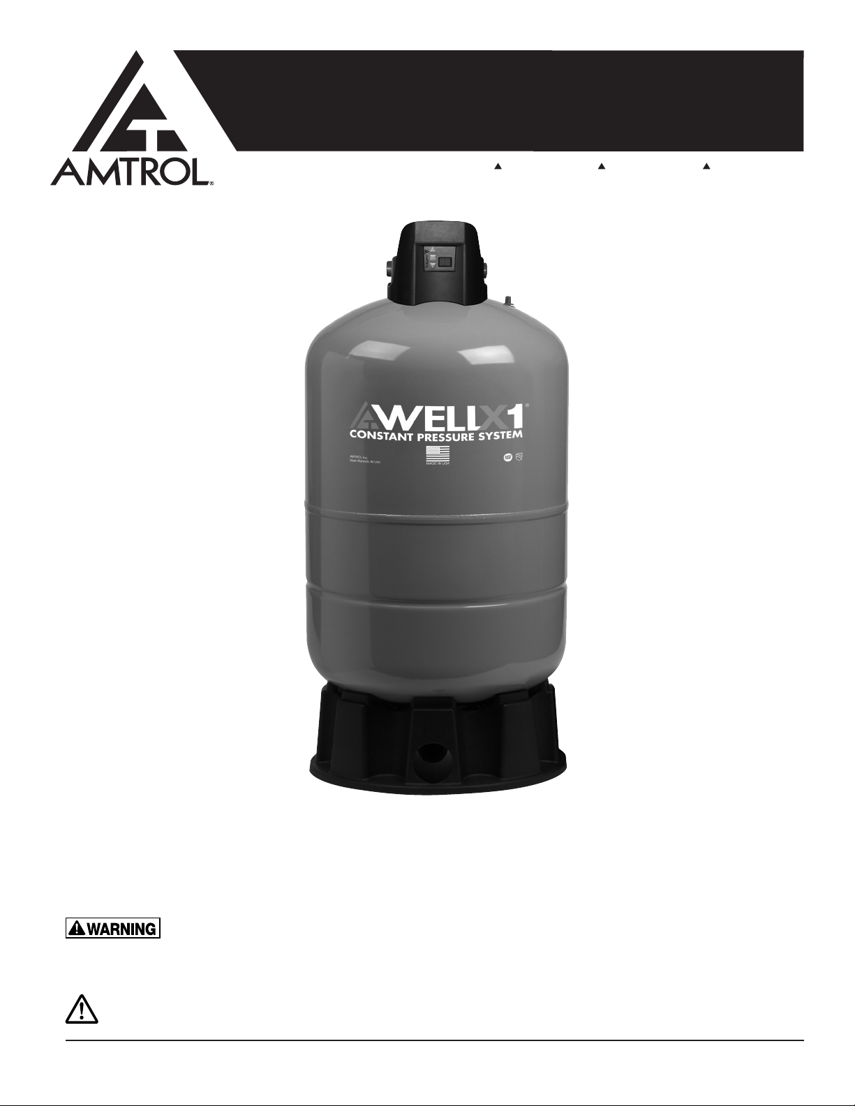
WELL-X-TROL® WELL-X1
®
with GUARDIAN CP™ Control
1400 Division Road, West Warwick, RI 02893 T: 401.884.6300 F: 401.885.2567 www.amtrol.com
INSTALLER: LEAVE THIS MANUAL WITH THE OWNER
The WELL-X1 tank comes with a 7 year warranty and the WELL-X1 digital control comes with a 2 year warranty. See back page for
warranty information
IMPORTANT GENERAL SAFETY INFORMATION - ADDITIONAL SPECIFIC SAFETY ALERTS APPEAR IN THE FOLLOWING INSTRUCTIONS.
READ CAREFULLY THE PRODUCT INSTALLATION, OPERATING AND MAINTENANCE MANUAL. FAILURE TO FOLLOW
THE INST RUCTIONS AND WARN INGS IN THE MAN UAL MAY RESULT IN SERIO US OR FATAL INJURY AN D/OR PROPERTY
DAMAGE, AND WILL VOID THE PRODUCT WARRANTY. THIS PRODUCT MUST BE INSTALLED BY A QUALIFIED PROFESSIONAL. FOLLOW
ALL APPLICABLE LOCAL AND STATE CODES AND REGULATIONS, IN THE ABSENCE OF SUCH CODES, FOLLOW THE CURRENT EDITIONS
OF THE NATIONAL PLUMBING CODE AND NATIONAL ELECTRIC CODE, AS APPLICABLE.
This is the safety alert symbol. It is used to alert you to personal injury hazards. Obey all safety instructions that follow this symbol
to reduce the risk of possible injury or death as well as property damage.
9013-0006 (03/11)
Page 2
1. TABLE OF CONTENTS
GENERAL SAFETY INFORMATION ........................................................... 2
COMPONENTS ............................................................................................ 3
INSTALLATION AND SIZING CONSIDERATIONS ..................................... 4
INSTALLATION CONSIDERATIONS .......................................................... 5
PLUMBING .................................................................................................. 6
WIRING ........................................................................................................ 8
STARTUP & ADJUSTMENT ........................................................................ 9
PUMP PROTECTION & DIAGNOSTICS ................................................... 13
TROUBLESHOOTING ............................................................................... 14
REPLACEMENT PARTS ........................................................................... 15
2. GENERAL SAFETY INFORMATION
This Product, like most Products under
pressure, may over time corrode. weaken
and burst or explode, causing serious or fatal injury, leaking
or ooding and/or property damage. To minimize risk, a
licensed professional must install and periodically inspect
and service the Product. A drip pan connected to an
adequate drain must be installed if leaking or ooding could
cause property damage. Do not locate in an area where
leakage of the tank or connections could cause property
damage to the area adjacent to the appliance or to lower
oors of the structure.
Chlorine & Aggressive Water: The water
quality can signicantly inuence the life of
this Product. You should test for corrosive elements, acidity,
total solids and other relevant contaminants, including
chlorine and treat your water appropriately to insure
satisfactory performance and prevent premature failure.
NOTE: Inspect for shipping damage and notify freight
carrier or store where purchased immediately if damage
is present. To avoid risk of personal injury and property
damage, if the product appears to be malfunctioning or
shows signs of corrosion, call a qualied professional
immediately. Current copies of the Product manual can be
viewed at www.amtrol.com. Use proper safety equipment
when installing.
ELECTROCUTION AND EXPLOSION HAZARD! Before
work is performed on the Product, turn off the power to the
Product and release all pressure in the system.
As in all plumbing products and water
storage vessels, bacteria can grow in this
Product, especially during times of non-use. Consult your
local plumbing professional regarding any steps you may
wish to take to safely disinfect your home’s
plumbing system.
REDUCTION OF THE PUMP CYCLE TIME OR THE PRECHARGE PRESSURE COMPARED TO ITS INITIAL SETTING.
THIS IS BECAUSE REDUCTION IN PUMP CYCLE TIME CAN
RESULT FROM LOSS OF TANK AIR PRESSURE WHICH IN
TURN CAN MEAN THERE MAY BE INTERNAL CORROSION
AND ANY RE-PRESSURIZATION OR ADDITIONAL
PRESSURE COULD RESULT IN RUPTURE OR EXPLOSION,
AND/OR PROPERTY DAMAGE.
RELIEF VALVE REQUIRED. A relief valve
has been installed which is set to open at
excessive pressures (100 psig or more). This will protect the
Well-X1® and other system components should the pressure
switch malfunction and fail to shut the pump off. The relief
valve is installed at the connection of the Well-X1® to the
system piping.
Before attempting any service and
disassembly, shut off power to the pump.
Ensure power is disconnected prior to removing motor.
Ensure power is disconnected before cleaning
is attempted.
This control is capable of running pumps
to pressures that may exceed the
limitations of system components. Never set the operation
pressure higher than that of the safe system capacity.
This control can be adjusted to a narrow
pressure differential. This can cause the
pump to cycle rapidly with an improperly sized tank, leading
to pump damage. This may require a larger pressure tank
than normally used.
Every Well-X1® is air tested to 150 psig,
the maximum working pressure for
the Well-X1®.
DANGER! EXPLOSION HAZARD, WHEN
THE WELL-X1® HAS BEEN IN SERVICE
AND A CHANGE TO A HIGHER PRE-CHARGE PRESSURE
IS NECESSARY DUE TO A REQUIRED CHANGE IN THE
PRESSURE SWITCH SETTING, FAILURE TO FOLLOW
INSTRUCTION MANUAL CAN CAUSE A RUPTURE OR
EXPLOSION, POSSIBLY CAUSING SERIOUS OR FATAL
INJURY, AND/OR PROPERTY DAMAGE. • DO NOT ADJUST
THE PRE-CHARGE PRESSURE IF THERE HAS BEEN A
The pump controller is not a disconnect.
The pump may be activated at any time.
The electrical system must be considered energized at all
times unless the circuit breaker is open. The disconnect for
the controller must break all incoming power lines. As with
a mechanical pressure switch, when installed with three
wire 230 vac pumps or any 3-phase pump, a standard pump
motor starter or a relay must be used.
2
Page 3
3. COMPONENTS
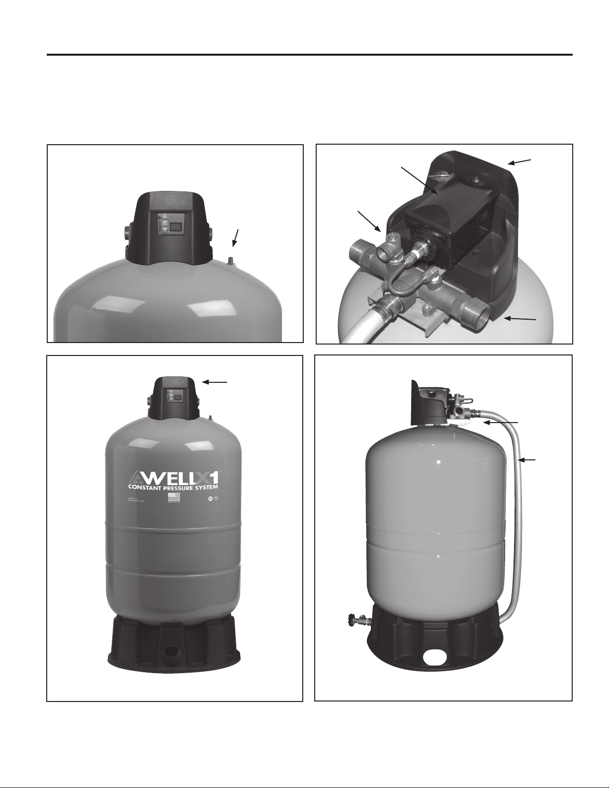
The Well-X1® combines all the standard well tank components in a single, easy to install package. The pressure tank,
control and tank ttings are factory-installed. After removing from the carton, inspect the Well-X1 for damage and ensure
all components are present.
AIR CHARGING
VALV E
CONTROL
GUARDIAN CP™ CONTROL
RELIEF VALVE
COVER
WATER
CONNECTIONS(2)
MOUNTING
BRACKET
PRESSURE
TANK
DRAIN
TANK
TUBING
3
Page 4
4. INSTALLATION AND SIZING CONSIDERATIONS
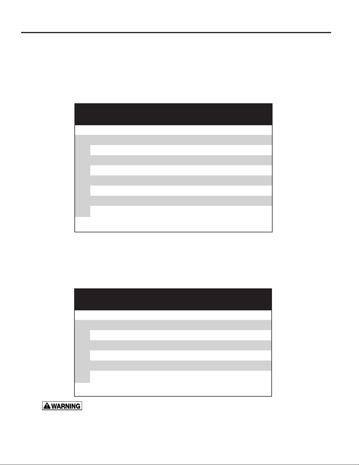
The Well-X1® functions like a traditional pressure switch by cycling the pump on and off. The factory pressure settings
are 40 psi cut-in and 60 psi cut-out. The controller allows these settings to be adjusted to best suit the application. The
Well-X1® can operate in two primary modes:
A. STANDARD OPERATION
Using a standard 20 psi differential, the Well-X1® can be sized according to the chart below. In this
application, the sizing and performance will be similar to a traditional pressure tank and mechanical
switch combination.
WELL-X1® SELECTION FOR STANDARD SYSTEMS
Control Setting (cut-in/cut-out) (psi)
30/50 40/60 50/70 60/80
4 WX1-250 WX1-250 WX1-250 WX1-250
5 WX1-250 WX1-250 WX1-250 WX1-250
7 WX1-250 WX1-250 WX1-250 WX1-250
10 WX1-250 WX1-250 WX1-250 WX1-251
12 WX1-250 WX1-250 WX1-251 WX1-251
PUMP GPM
15 WX1-251 WX1-251 WX1-302 WX1-302
18 WX1-251 WX1-302 WX1-302 WX1-302
20 WX1-302 WX1-302 WX1-302 -
B. CONSTANT PRESSURE MODE
The Well-X1® control allows a narrow differential to provide consistent water pressure. The factory 20
psi differential can be reduced so the cut-in and cut-out pressures are within 10 psi. When installed as
a constant pressure system, the chart below should be used to ensure the tank volume is sufcient to
provide adequate cycle protection.
WELL-X1® SELECTION FOR CONSTANT PRESSURE
Control Setting (cut-in/cut-out) (psi)
40/50 50/60 60/70 70/80
4 WX1-250 WX1-250 WX1-250 WX1-250
5 WX1-250 WX1-250 WX1-250 WX1-250
7 WX1-250 WX1-250 WX1-251 WX1-251
10 WX1-251 WX1-251 WX1-302 WX1-302
PUMP GPM
12 WX1-251 WX1-302 WX1-302 WX1-302
15 WX1-302 WX1-302 - -
A relief valve has been installed which is set to open at excessive pressures (100 psig or
more). Do not exceed the pressure setting of the relief valve.
4
Page 5

5. INSTALLATION CONSIDERATIONS
LOCATION
The Well-X1® is designed for indoor and outdoor installations. The NEMA 3 enclosure can be installed in
direct weather. If installed outdoors, be sure the following conditions are met:
• Do not install where ambient temperatures can drop below freezing
or exceed 120° F.
• Use water-tight: wiring conduit, wire nuts and conduit connections
as dictated by applicable codes and ordinances.
• Protect the piping from mechanical damage.
• Install the relief valve blow down tube where venting water will not
cause personal injury or damage the surrounding property.
• Drip Pan and Drain: To avoid leaking and/or property damage,
install with a drip pan connected to an adequate working drain kept
clear at all times.
ORIENTATION
Ensure the installation meets all applicable local codes and is installed by a qualied professional.
Additionally, the following should be noted.
• This unit is designed for vertical installation above ground only.
Do not install horizontally or directly bury the unit. The Well-X1®
may be installed below grade in a well pit or other suitable
enclosure. Do not locate in an area where leaking or ooding
could cause property damage to surrounding areas.
• Check codes to determine if there are any height requirements
pertaining to the Well-X1®. Particularly, ensure the bottom
drain meets these requirements. If restrictions are imposed on
the proximity of drain connections to the oor, the unit may be
elevated on blocks or the bottom drain tube can be removed and
plugged, after which a sampling tap may be installed in the water
lines near the top of the Well-X1®.
5
Page 6
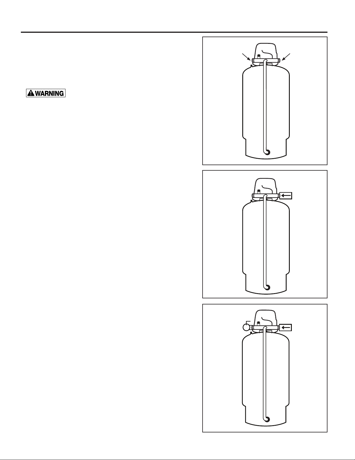
6. PLUMBING
1. Plumbing connections are similar to a traditional "tank
cross" or "tank tee". Provisions are made for popular line
sizes via a 1-1/4" NPT male outer thread and a 1" NPT
female inner thread. The plumbing connections are not
directional and allow ow from either side. When attaching
valves or ttings, uses the wrench ats provided.
EXPLOSION HAZARD. Failure to
follow these instructions can cause a
rupture or explosion possibly causing serious or fatal
injury, ooding, and/or property damage.
2. Install the supply piping from the well pump. If required,
install a spring-loaded check valve.
WATER
CONNECTIONS
CHECK
VALVE
3. Install a shutoff (service) valve on the outgoing line. This
will allow the Well-X1® to be tested prior to pressurizing
the entire system. DO NOT place a shutoff on the
incoming supply line.
NOTE: The relief valve is sized for a maximum ow rate
of 10 gpm at 125 psi. If the pump installation allows higher
ow rates, an additional relief valve must be installed.
6
Page 7
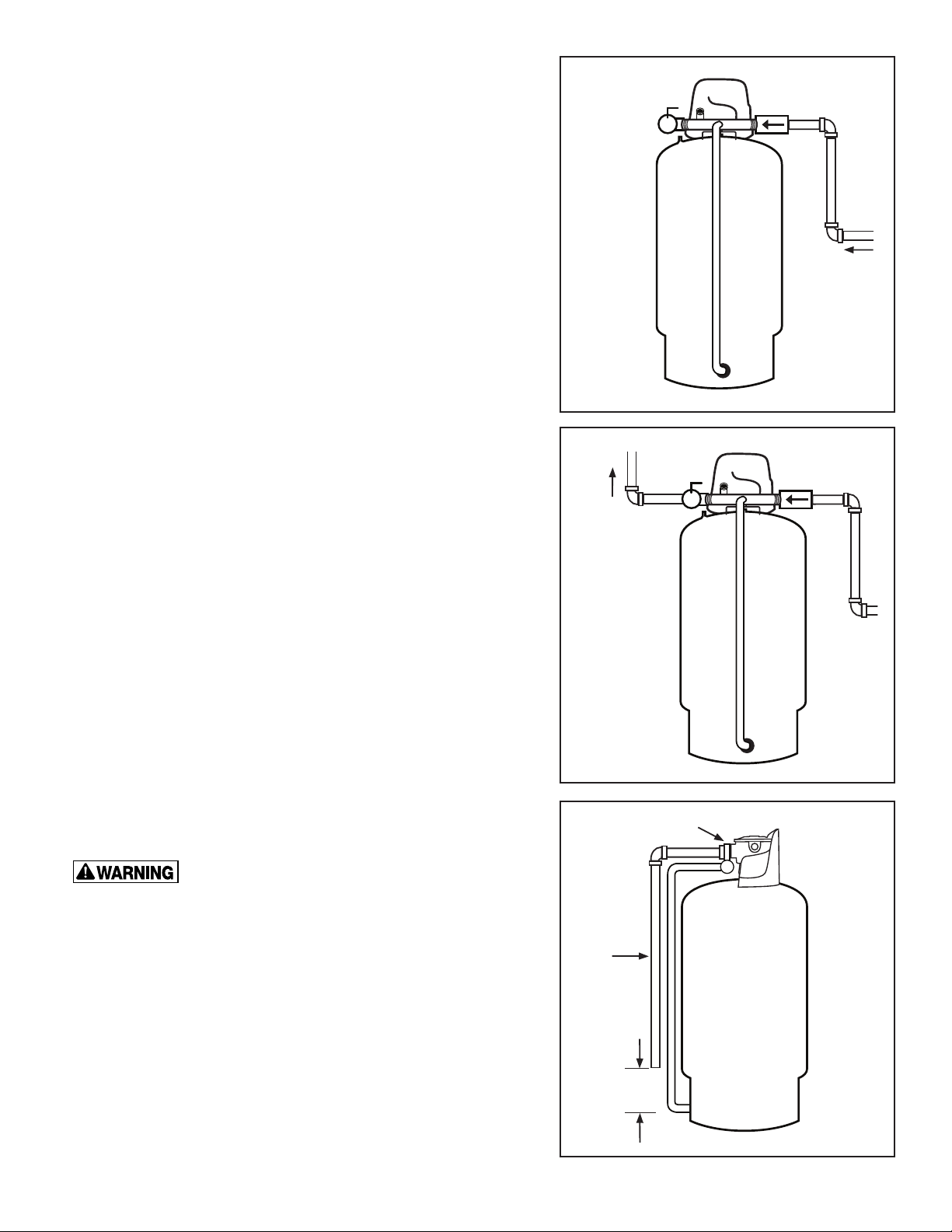
4. Connect the water line from the well pump to the inlet of
the Well-X1®.
5. Plumb the outgoing supply to the building's water
supply system or into the water treatment equipment
(if present).
FROM
WELL
TO
SYSTEM
6. Install a blow down tube from the relief valve to a drain
or to within 6" of the oor as required by local codes.
A drip pan connected to an adequate
drain must be installed if leaking or
ooding could cause property damage.
RELIEF
VALVE
BLOWDOWN
TUBE
6”
7
Page 8
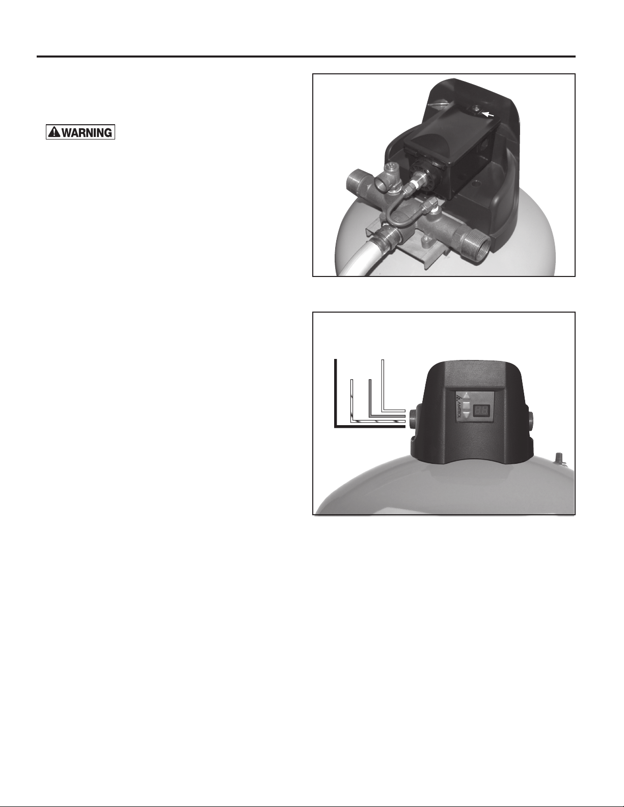
7. WIRING
1. Shut off the circuit breaker for the well system. Loosen
the silver screw on top of the control and remove cover
to expose the control wires.
Electrocution hazard. For your safety,
the information in this manual must be followed to
minimize the risk of electric shock, property damage
or personal injury. Properly ground to conform with all
governing codes and ordinances.
2. The 12 gauge wire leads are pre-stripped and ready
to accept standard wire nuts. Each wire is color coded
to correspond with the diagram below. Use water tight
conduit, connections, and wire nuts for an outside
application.
SCREW
3. Wiring is similar to a traditional mechanical pressure
switch. Two leads are connected to line supply, while
the other supply the pump motor or starter. Wire the
control to the line supply and pump motor or pump
starter as required by the manufacturer's instructions.
It is recommended that service switch be installed in
addition to the circuit breaker. The disconnect for the
controller must break all incoming power lines. This
should interrupt line voltage and be installed near the
Well-X1® and labeled appropriately.
4. After completing the wiring, reattach top cover and
tighten screw. Ensure no loose wires protrude from the
control.
LINE
WHITE/STRIPE
BLACK
MOTOR
MOTOR
BLUE
LINE
WHITE
8
Page 9
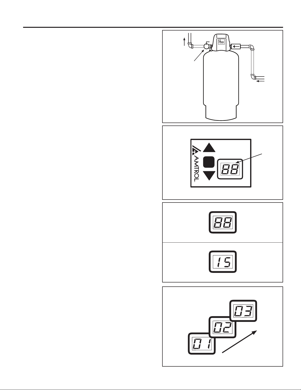
8. STARTUP & ADJUSTMENT
1. After plumbing and wiring are complete, close the
service valve to allow startup without pressurizing the
entire plumbing system. If a service valve was not
installed, close all xtures in the home. Ensure the
bottom drain is closed.
2. Restore power to the Well-X1® by turning on the breaker
and electrical service switch (if installed). The display
will illuminate.
TO
SYSTEM
CLOSE
SERVICE
VALVE
FROM
WELL
DISPLAY
3. The display will read "88" to test the display illumination,
then a number identifying the control type (i.e. 15). This
number is for factory use and may vary by model and
manufacture date.
4. After a slight pause, the pump will start and the system
pressure will be displayed. This number will increase
as the pump runs and the tank lls.
Note: Some jet pumps may be difcult to prime,
resulting in the low water cut-off activating if pressure
will not build above 10 psig. Depressing the s arrow
will temporarily override the low water cut-off to allow
proper priming.
9
Page 10
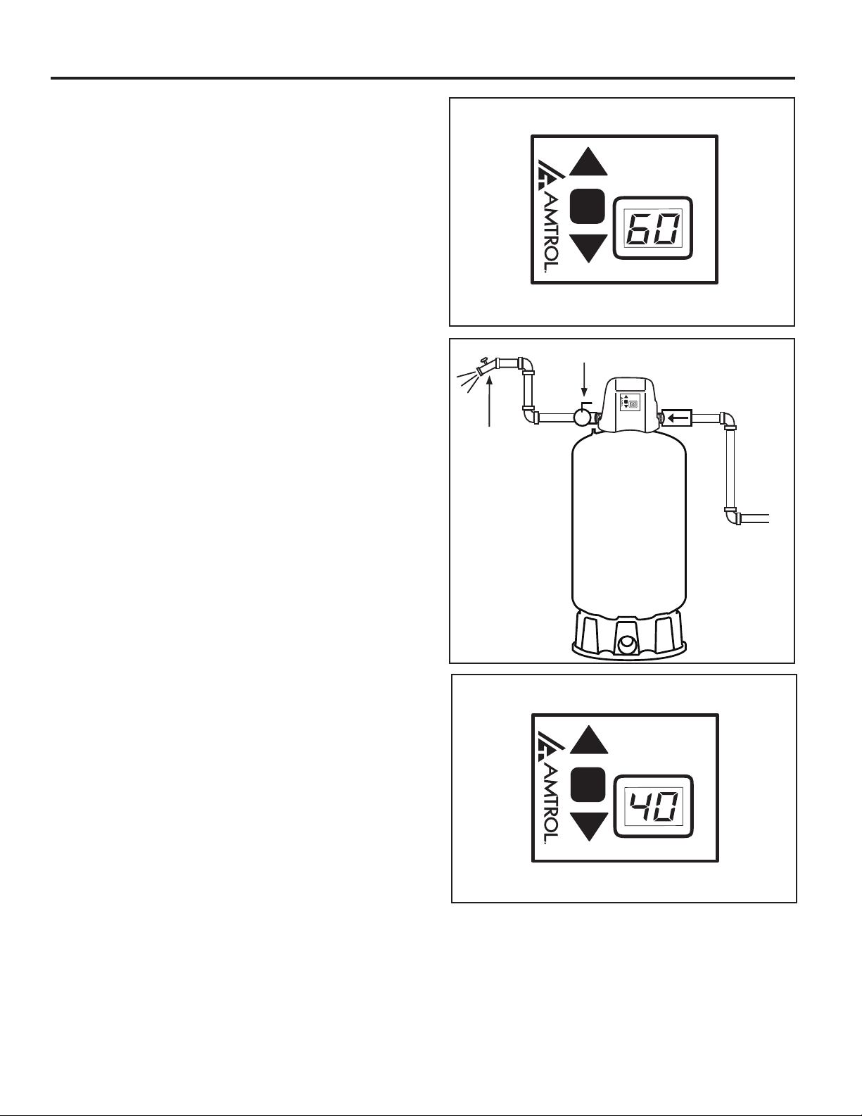
8. STARTUP & ADJUSTMENT (con't)
5.The factory cut-out (pump off) setting is 60 psig.
When the pump reaches 60 psig, the Well-X1® will
shut the pump off. Check the plumbing for leaks and
repair before continuing. If during startup the cutout setting of 60 psig cannot be reached, read the
adjustment instructions to lower the cut-out within the
pump's capability.
6. Slowly open the service valve to allow the system to
pressurize. The pressure may drop slightly during this
process. After the valve is fully open, open the xture
closest to the Well-X1® to begin drawing water from
the tank.
7. When the system reaches the factory cut-in (pump on)
setting of 40 psig, the pump will start. Like a traditional
mechanical switch, the pressure will begin to rise,
repeating the cycle. If desired, the Well-X1® settings
can now be adjusted as shown below.
OPEN SERVICE VALVE
TO PRESSURIZE SYSTEM
OPEN CLOSEST
FIXTURE TO
DRAW WATER
10
Page 11
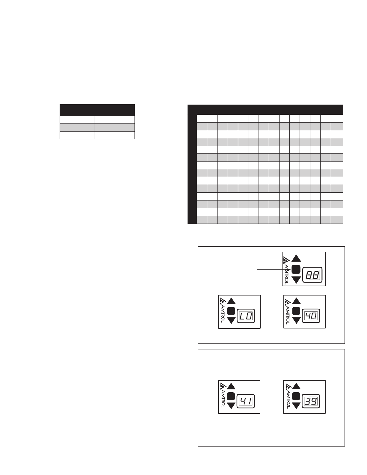
PRESSURE ADJUSTMENT
The Well-X1® utilizes a simple cut-in/cut-out adjustment. Before setting the desired operating range, refer to the chart
below to ensure the Well-X1's Maximum Acceptance is not exceeded. Adjust the precharge as shown on page 12.
CAUTION! Exceeding Maximum Acceptance will reduce tank life and cause irreparable damage.
Step 1: Find the Maximum Acceptance for the installed
Well-X1® model.
MODEL
WX1-250
WX1-251
WX1-302
MAXIMUM
ACCEPTANCE
.77
.55
.54
1. To enter the programming mode, press and hold the
■ button until LO appears. This is the cut-in setting.
Factory default will be 40 psi.
Step 2: Ensure the desired operating range does not
exceed that model's Maximum Acceptance.
CUT-OUT PRESSURE
20 25 30 35 40 45 50 55 60 65 70 75 80
10 .28 .38 .45 .50 .55 .59 .62 .65 .67 .69
15 .25 .34 .40 .46 .50 .54 .57 .60 .63 .65
20 .22 .30 .37 .42 .46 .50 .64 .57 .59 .61
25 .20 .27 .34 .39 .43 .47 .50 .53 .56 .58
30 .18 .25 .31 .36 .40 .44 .47 .50 .53
35 .17 .23 .29 .34 .38 .41 .45 .48
40 .16 .22 .27 .31 .35 .39 .42
45 .14 .20 .25 .30 .33 .37
50 .13 .19 .24 .28 .32
CUT-IN PRESSURE
55 .13 .18 .22 .26
60 .12 .17 .21
65 .12 .16
70 .11
PRESS AND
HOLD TO
UNLOCK AND
SET CUT-IN
2. Use the s and t arrows to raise or lower the cut-
in setting. Adjustment can be made within 10 psig or
as wide as 55 psig of the cut-out setting to 60 psig. If
this range is exceeded, the display will cease to change
even though the button is being pressed.
Minimum setting is 10 psig.
11
t
t
Page 12
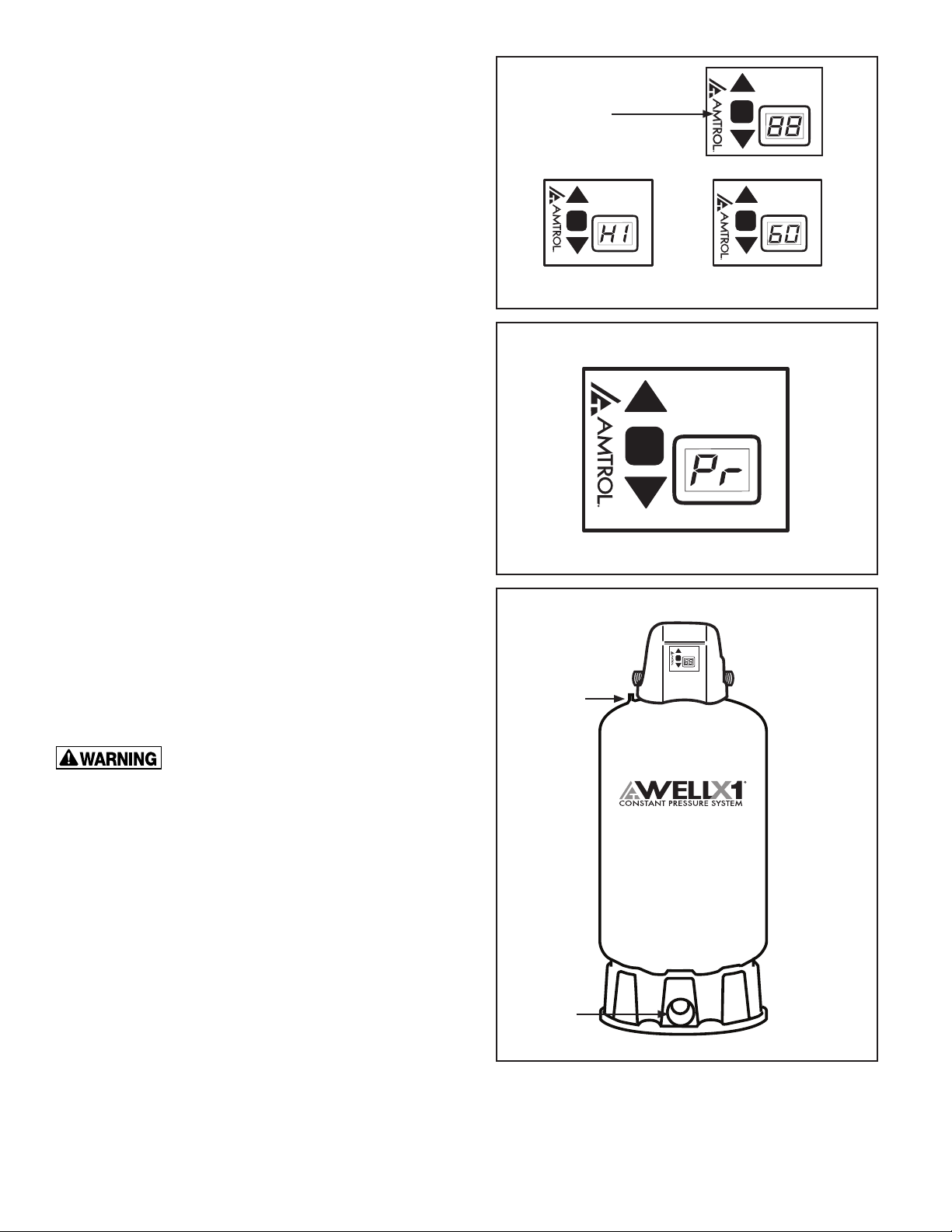
3. To adjust the cut-out, depress ■ once and the display
will read HI. Again, press thetor s buttons to raise
or lower the setting. The same 10-55 psig differential
range applies.
Maximum setting is 80 psig.
4. After adjusting the cut-in and cut-out, release the buttons.
After a slight pause, Pr will be displayed, indicating the
settings are saved in the event of a power outage.
PRESS AGAIN
TO SET
CUT-OUT
PRECHARGE ADJUSTMENT
Whenever the cut-in (LO) setting is changed, the tank
precharge must be adjusted. To do this, shut the Well-X1®
off and open the drain to empty all water. Using an air
gauge, adjust the precharge to 2 psig below the cut-in
(LO) setting.
Failure to adjust the precharge will result in tank damage
or water interruption.
DANGER! Explosion Hazard. If the
Well-X1® has been in service and a change to a higher
pre-charge is necessary due to a required change in
the setting, failure to follow instruction below can cause
a rupture or explosion, possibly causing serious or fatal
personal injury, and/or property damage.
• Do not adjust or add pressure if there has been a loss
of air.
• Do not adjust the pre-charge pressure if there is visible
exterior corrosion.
• Do not adjust the pre-charge pressure if there has
been a reduction in pump cycle time or the precharge pressure compared to its initial setting. This is
because reduction in pump cycle time can result from
loss of tank air pressure which in turn can mean there
may be internal corrosion and any re-pressurization
or additional pressure could result in rupture
or explosion.
AIR VALVE
DRAIN
12
Page 13
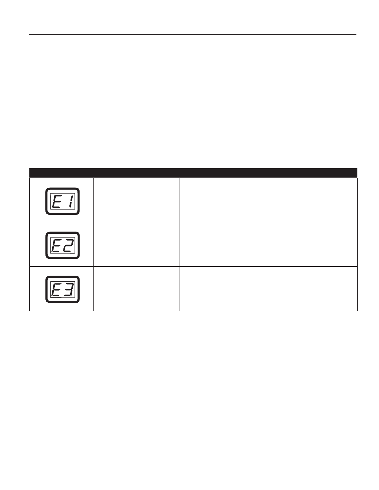
9. PUMP PROTECTION AND DIAGNOSTICS
The Well-X1® continually monitors pressure, cycle time and voltage to protect the well pump. The following error codes
alert the user to a potential problem, prompting service.
E1: Rapid Cycle
E2: Low Suction (low water cut-off)
E3: Voltage Protection
WELL-X1® ERROR CODES
When an error occurs, the display will ash a diagnostic code.
ERROR CODE POSSIBLE CAUSES AND CONTROL ACTION
Multiple cycles below a safe runtime indicate an incorrect
E1: Rapid Cycle
precharge, undersized Well-X1® or waterlogged tank. Pump
continues to run.
E2: Low Suction
E3: Voltage Protection
Pump operation below 10 psi indicates a low well level, well
piping leak, insufcient prime, failing pump or loose wiring.
Pump will shut down and attempt to restart every 60 minutes.
If line voltage varies outside a safe operating range, low or
high, the control will run for up to two minutes to ensure water
is available, then shut the pump off until voltage is restored to a
normal range.
13
Page 14
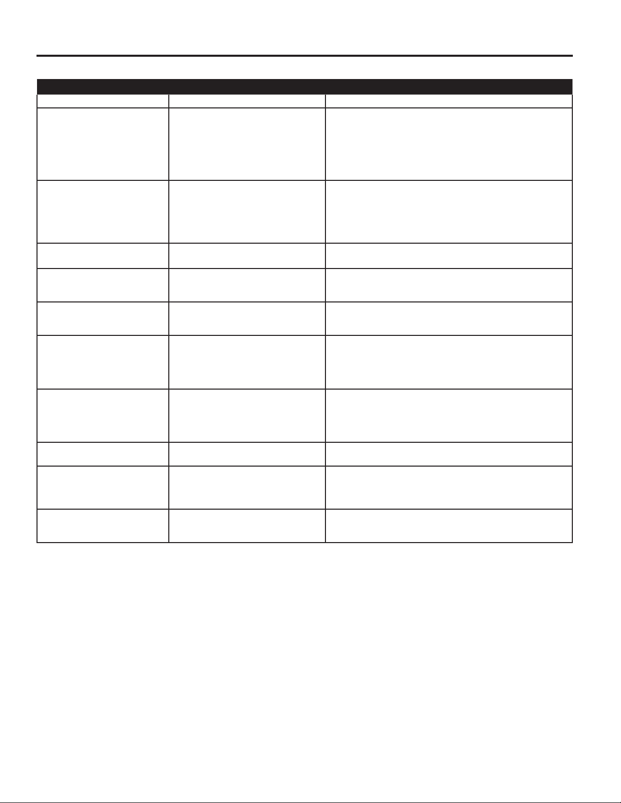
10. TROUBLESHOOTING
PROBLEM POSSIBLE CAUSE SOLUTION
Error code ashes 1. Error encountered 1. See Error Code section for possible causes.
No water at xtures 1. Error encountered
Low water pressure 1. Pressure setting too low
Intermittent water interruption 1. Tank precharge too high
No pressure (pump runs) 1. No pump prime (jet pumps)
Display will not illuminate 1. Circuit breaker or switch off
Pump will not turn on
(Display illuminated)
Pump will not shut off 1. Pressure setting too high
Sediment or discoloration in water 1. Poor water quality 1. Install proper treatment equipment, drain and ush tank per
Rapid pump cycling 1. Differential too narrow
Relief valve discharges 1. Over-pressure condition
2. No power
3. Water line obstructed
4. Faulty pump
5. Drain or relief valve open
6. Leak in plumbing
2. Water line obstructed
3. Faulty pump
4. Pressure setting out of range
5. Incorrect wiring
2. Recurring error
2. Failing well pump
3. Incorrect wiring
2. Faulty or loose wiring
3. Failed control
1. Error encountered
2. Faulty pump
3. Failed control
4. Pressure sensor line blocked
5. Loose or faulty wiring
2. Pump water line obstructed
3. Pump problem
4. Failed control
2. Improper precharge
3. Failed tank
2. Faulty relief valve
1. See Error Code section for possible causes.
2. Check circuit breaker and wiring.
3. Ensure shut-off valves are open, check ltration equipment
(if installed).
4. Repair or replace as necessary.
5. Ensure valves are closed.
6. Check piping.
1. Adjust pump cut-in and cut-out setting as described in manual.
2. Ensure shut-off valves are open, check ltration equipment
(if installed).
3. Check well pump.
4. Reduce pressure settings within pump capacity.
5. Check pump wiring.
1. Adjust air pressure 2 psi below cut-in setting.
2. See Error Code section for possible causes.
1. Prime pump and restart.
2. Repair or replace as necessary.
3. Check pump wiring.
1. Check breaker and service switch.
2. Check line supply wiring.
3. Replace.
1. See Error Code section for possible causes.
2. Repair or replace as necessary.
3. Replace.
4. Remove and clean.
5. Check pump wiring.
1. Decrease pressure settings until pump an reach cut-out.
2. Ensure no shut-offs are closed between pump and Well-X1™.
3. Inspect well pump condition and sizing if pump cannot reach a
reasonable cut-out setting.
4. Replace.
instructions contained in this manual.
1. Check sizing for intended operating range or spread differential
to obtain proper pump run time.
2. Adjust air pressure 2 psi below cut-in setting.
3. Replace.
1. See "Pump will not shut off" above.
2. If pressure is below 100 psi, relief valve should not open.
Replace if faulty.
14
Page 15
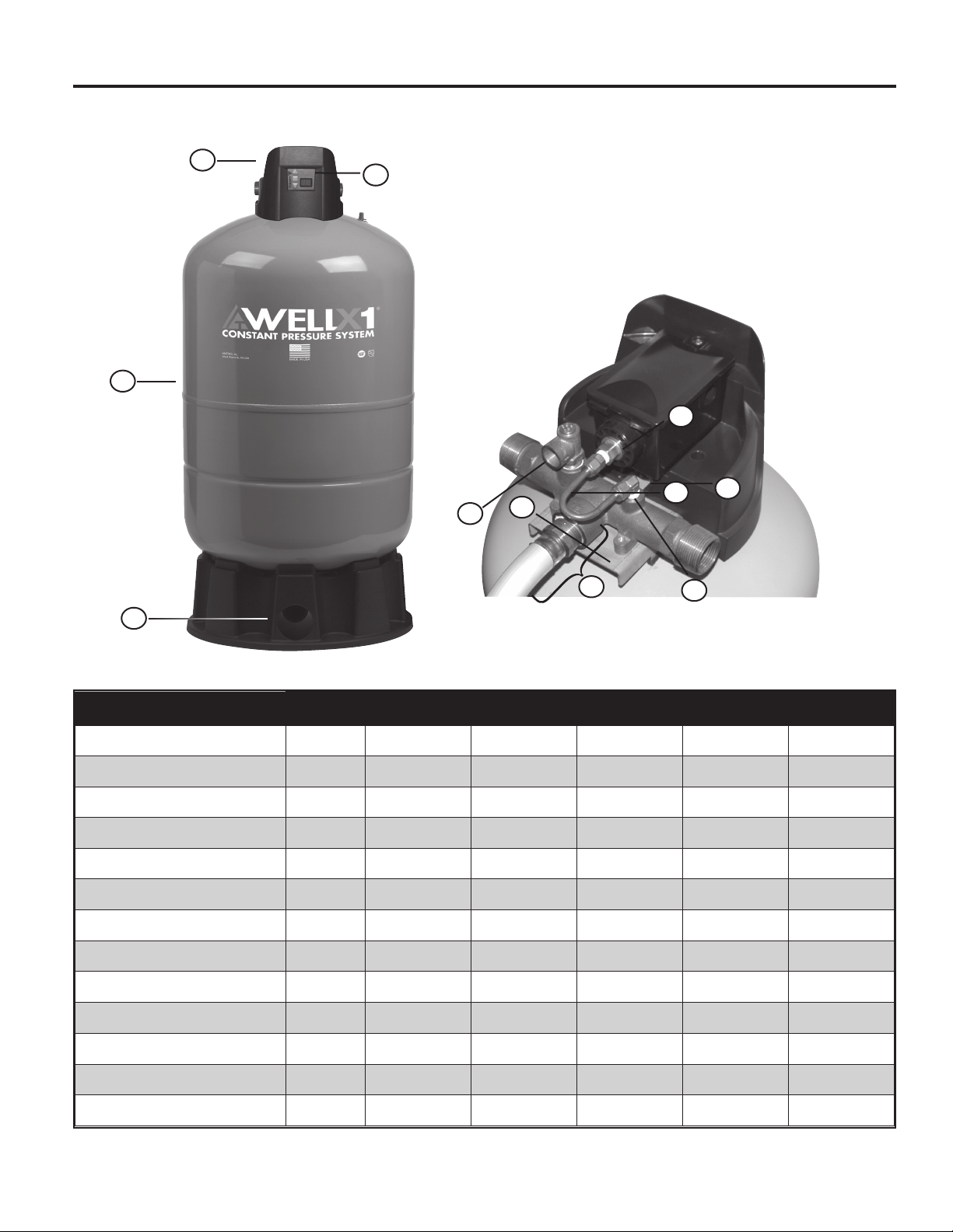
11. REPLACEMENT PARTS
3
1
2
8
12
7
10
4
6
9
11
DESCRIPTION
Replacement tank: Blue 1 144R273 146R825 145R379 145R380 150R92
Electronic control 2 146R2321 146R2321 146R2321 146R2321 146R2321
Control cover 3 146R2333 146R2333 146R2333 146R2333 146R2333
Mounting bracket 4 146R2336 146R2336 146R2336 146R2336 146R2336
Brass tee only (no accessories) 5 140R517 140R517 140R517 140R517 140R517
Pressure sensor tubing 6 9403R197 9403R197 9403R197 9403R197 9403R197
Pressure sensor tting (elbow) 7 9401R100 9401R100 9401R100 9401R100 9401R100
Pressure sensor tting (straight) 8 9403R195 9403R195 9403R195 9403R195 9403R195
Tank tubing replacement kit w/tting
Relief valve, 100 psig 10 9403R191 9403R191 9403R191 9403R191 9403R191
Drain assembly 11 196R0003 196R0003 166R0013 166R0013 166R0014
POSITION
9 9403R199-5 9403R199-4 9403R199-3 9403R199-2 9403R199-1
WX1-202 WX1-203 WX1-250 WX1-251 WX1-302
Mounting knob 12 9403R194 9403R194 9403R194 9403R194 9403R194
Replacement carton Not Shown 9196R0003 9196R0006 9166R013 9166R016 9166R019
15
Page 16

AMTROL INC. LIMITED PRODUCT WARRANTY
Products covered: all Products manufactured by AMTROL Inc. (“AMTROL”) .
This warranty cannot be transferred – it is extended only to the original Purchaser or First User of the Product. By accepting and keeping this Product
you agree to all of the warranty terms and limitations of liability described below.
IMPORTANT WARNING – READ CAREFULLY THE INSTALLATION, OPERATING AND MAINTENANCE INSTRUCTIONS MANUAL (“MANUAL”) to
avoid serious personal injury and/or property damage and to ensure safe use and proper care of this product
Who Receives AMTROL’s Product Warranty
All purchasers or first users of the new Product. The Warranty is non-transferable.
What is covered by this Warranty
AMTROL warrants to the purchaser or first user of the new Product that at the time of manufacture, the Product is free from defects in material and
workmanship. Any warranty claim must be made within one (1) year unless another time period is set forth in the Manual, measured from the
time the Product was purchased.
What AMTROL Will Do If You Have a Covered Warranty Claim
In the event of a breach of the foregoing warranty, AMTROL will at its option either make repairs to correct any defect in material or workmanship or
supply and ship either new or used replacement parts or products. AMTROL will not accept any claims for labor or other costs.
What This Warranty Does Not Cover - Exclusions and Limitations
This Warranty does not cover any failure or problem unless it was caused by a defect in material or workmanship. In addition, this Warranty shall not
apply:
• if the Product is not correctly installed, operated, repaired or maintained as described in the Manual provided with the Product;
• to any failure or malfunction resulting from abuse (including freezing); improper or negligent: handling, shipping (by anyone other than AMTROL),
storage, use, operation, accident; or alteration, lightning, flood or any other environmental condition;
• to any failure or problem resulting from the use of the Product for any purpose other than those specified in the accompanying Manual or alteration
of any part of the product;
• this Warranty does not cover labor costs, shipping charges, service charges, delivery expenses, administrative fees or any costs incurred in
removing or reinstalling the Product;
• this Warranty does not cover any claims submitted to AMTROL or an AMTROL-authorized distributor or retailer more than 30 days after expiration
of the applicable warranty time period described in this Warranty;
• this Warranty also does not cover repair or replacement costs not authorized in advance by AMTROL.
Additional Warranty Limitations
ALL IMPLIED WARRANTIES, INCLUDING THE IMPLIED WARRANTIES OF MERCHANTABILITY AND FITNESS FOR A PARTICULAR
PURPOSE ARE SPECIFICALLY DISCLAIMED.
Limitations of Remedies
THE REMEDIES CONTAINED IN THIS WARRANTY ARE THE PURCHASER’S OR FIRST USER’S EXCLUSIVE REMEDIES. IN NO
CIRCUMSTANCES WILL AMTROL BE LIABLE FOR MORE THAN, AND PURCHASER-FIRST USER’S REMEDIES SHALL NOT EXCEED, THE
PRICE PAID FOR THE PRODUCT. IN NO CASE SHALL AMTROL BE LIABLE FOR ANY SPECIAL, INDIRECT, INCIDENTAL OR CONSEQUENTIAL
DAMAGES, WHETHER RESULTING FROM NON-DELIVERY OR FROM THE USE, MISUSE, OR INABILITY TO USE THE PRODUCT OR FROM
DEFECTS IN THE PRODUCT OR FROM AMTROL’S OWN NEGLIGENCE OR OTHER TORT. This exclusion applies regardless of whether such
damages are sought for breach of warranty, breach of contract, negligence, strict liability, in tort or under any other legal theory. Such damages include,
but are not limited to, inconvenience, loss or damage to property, mold, loss of profits, loss of savings or revenue, loss of use of the Products or any
associated equipment, facilities, buildings or services, downtime, and the claims of third parties including customers.
What To Do If You Have a Problem Covered By This Warranty
Any covered Warranty service must be authorized by AMTROL. Contact the person from whom you purchased the Product, who must
receive authorization from an AMTROL distributor or AMTROL. If you do not receive a prompt response, call AMTROL directly at
877-517-9673. Notice of a Warranty claim should be submitted by the authorized distributor to AMTROL at the following address:
AMTROL Inc., Warranty Claim Dept.
1400 Division Road, West Warwick, RI 02893
Before AMTROL determines to provide any replacement part or Product, it may as a pre-condition to making such a determination require that the
warranty claimant ship the Product, postage prepaid to an authorized AMTROL distributor, or to AMTROL and provide proof of purchase evidenced by
the original sales receipt or Product registration.
Replacement Product Warranty
In case of replacement of a Product or any component part, AMTROL reserves the right to make changes in the design, construction, or material of the
substitute components or products, which shall be subject to all of the terms and limitations of this Warranty, except that the applicable warranty periods
shall be reduced by the amount of time the warranty claimant owned the product prior to submitting notification of the warranty claim.
Revised 01/11
1400 Division Road, West Warwick, RI 02893 T: 401.884.6300 F: 401.885.2567 www.amtrol.com
AMTROL, AMTROL logo, GUARDIAN CP and Well-X1 are registered trademarks of AMTROL Inc. and afliates
in the U.S. and elsewhere. All rights reserved.
Part #: 9013-0006 (03/11)
 Loading...