

Amtrol WX-205, WX-102PS, WX-110PS, WX-200PS, WX-202PS Installation & Operation Instructions
...Page 1
WELL-X-TROL
®
RESIDENTIAL PRE-PRESSURIZED WELL TANKS
INSTALLATION & OPERATION INSTRUCTIONS
Models WX-101 through WX-350
NOTE: Inspect for shipping damage and notify freight carrier or store where purchased immediately if damage is present. To avoid risk of personal
injury and property damage, if the product appears to be malfunctioning or shows signs of corrosion, call a qualified professional immediately. Current
copies of the Product manual can be viewed at www.amtrol.com. Use proper safety equipment when installing.
THIS IS THE SAFETY ALERT SYMBOL. IT IS USED TO ALERT YOU TO POTENTIAL PERSONAL INJURY AND OTHER
HAZARDS. OBEY ALL SAFETY MESSAGES THAT FOLLOW THIS SYMBOL TO REDUCE THE RISK OF PERSONAL
INJURY AS WELL AS PROPERTY DAMAGE.
READ CAREFULLY THE PRODUCT
INSTALLATION & OPERATION INSTRUCTIONS.
FAILURE TO FOLLOW THE INSTRUCTIONS AND WARNINGS IN THE
MANUAL MAY RESULT IN SERIOUS OR FATAL INJURY AND/OR
PROPERTY DAMAGE, AND WILL VOID THE PRODUCT WARRANTY.
THIS PRODUCT MUST BE INSTALLED BY A LICENSED
PROFESSIONAL. FOLLOW ALL APPLICABLE LOCAL AND STATE
CODES AND REGULATIONS. IN THE ABSENCE OF SUCH CODES,
FOLLOW THE CURRENT EDITIONS OF THE NATIONAL PLUMBING
CODE AND NATIONAL ELECTRIC CODE, AS APPLICABLE.
EXPLOSION OR RUPTURE HAZARD. THE WELL TANK MUST BE
OPERATED SO THAT THE PRESSURE DOES NOT EXCEED THE
MAXIMUM WORKING PRESSURE.
EXPLOSION HAZARD. Failure to follow the
instructions in the product manual can cause a
rupture or explosion; possibly causing serious or fatal injury, leaking or
flooding and/or property damage.
Use only with a potable water system. Do not
operate in a setting with freezing temperatures or
where the temperature can exceed 130°F and do not exceed the
maximum working pressure specified for this Product in the Manual.
Mount vertically only.
Chlorine & Aggressive Water: The water quality
can significantly influence the life of this Product.
You should test for corrosive elements, acidity, total solids and other
relevant contaminants, including chlorine and treat your water appropriately
to insure satisfactory performance and prevent premature failure.
causing serious or fatal injury, leaking or flooding and/or property damage.
To minimize risk, a licensed professional must install and periodically
inspect and service the Product. A drip pan connected to an adequate
drain must be installed if leaking or flooding could cause property damage.
Do not locate in an area where leakage of the tank or connections could
cause property damage to the area adjacent to the appliance or to lower
floors of the structure.
local code requirement or maximum working pressure designated in the
Product Manual, whichever is less. Do not expose Product to freezing
temperatures or temperatures in excess of 130°F. Do not adjust the precharge or re-pressurize this Product except for any adjustments required
at the time of initial installation, especially if Product is corroded,
damaged or has diminished integrity. Adjustments to pre-charge must
be done at ambient temperature only. Failure to properly size the
Product or follow these instructions may result in excessive strain on the
system, lead to Product failure, serious or fatal personal injury, leakage
and/or property damage.
cause cancer and birth defects or other reproductive harm. For more
information go to www.P65Warnings.ca.gov.
This Product, like most Products under pressure,
may over time corrode, weaken and burst or explode,
EXPLOSION OR RUPTURE HAZARD A relief valve
must be installed to prevent pressure in excess of
This product can expose you to chemicals including
lead, which is known to the State of California to
Page 2
PLEASE READ THE FOLLOWING INSTRUCTIONS CAREFULLY
IMPORTANT GENERAL SAFETY INFORMATION -
ADDITIONAL SPECIFIC SAFETY ALERTS APPEAR IN THE FOLLOWING INSTRUCTIONS.
DANGER! EXPLOSION HAZARD. WHEN THE
CHANGE TO A HIGHER PRE-CHARGE PRESSURE IS NECESSARY
DUE TO A REQUIRED CHANGE IN THE PRESSURE SWITCH
SETTING, FAILURE TO FOLLOW INSTRUCTIONS BELOW CAN
CAUSE A RUPTURE OR EXPLOSION, POSSIBLY CAUSING SERIOUS
OR FATAL PERSONAL INJURY, AND/OR PROPERTY DAMAGE.
•DONOT ADJUST OR ADD PRESSURE IFTHERE HAS BEENA
LOSS OF AIR.
• DO NOT ADJUST THE PRE-CHARGE PRESSURE IF THERE IS
VISIBLE EXTERIOR CORROSION.
•DO NOT ADJUST THE PRE-CHARGE PRESSURE IF THERE
HAS BEEN A REDUCTION OF THE PUMP CYCLE TIME OR
THE PRE-CHARGE PRESSURE COMPARED TO ITS INITIAL
SETTING. THIS IS BECAUSE REDUCTION IN PUMP CYCLE TIME
CAN RESULT FROM LOSS OF TANK AIR PRESSURE WHICH IN
TURN CAN MEAN THERE MAY BE INTERNAL CORROSION AND
ANY RE-PRESSURIZATION OR ADDITIONAL PRESSURE COULD
RESULT IN RUPTURE OR EXPLOSION.
for the Well-X-Trol line. Should pressures exceed 150 psig, proper
selection and sizing of an ASME Well-X-Trol should be made.
pressures (125 psig or more). This will protect the Well-X-Trol and other
system components should the pressure switch malfunction and fail to
shut the pump off. The relief valve should be installed at the connection
of the Well-X-Trol to the system piping and have a discharge equal to the
pump’s capacity at 125 psig.
YOUR WELL TANK, ESPECIALLY DURING TIMES OF NON-USE.
WELL TANK HAS BEEN IN SERVICE AND A
MAXIMUM WORKING PRESSURE. Every Well-X-Trol
is
tested to 150 psig, the maximum working pressure
RELIEF VALVE REQUIRED. A relief valve should
be installed which is set to open at excessive
AS IN ALL PLUMBING PRODUCTS AND WATER
STORAGE VESSELS, BACTERIA CAN GROW IN
CONSULT YOUR LOCAL PLUMBING OFFICIAL REGARDING ANY
STEPS YOU MAY WISH TO TAKE TO SAFELY DISINFECT YOUR
HOME’S PLUMBING SYSTEM.
A water test must be taken before installation of any
water treatment equipment.
DANGER! EXPLOSION HAZARD. IF YOU
ADJUST THE PRE-CHARGE PRESSURE OR ADD
PRESSURE TO A TANK THAT IS CORRODED OR DAMAGED OR
WITH DIMINISHED INTEGRITY, THE TANK CAN BURST OR EXPLODE,
POSSIBLY CAUSING SERIOUS OR FATAL PERSONAL INJURY AND/
OR PROPERTY DAMAGE.
•ONLY ADJUST THE PRE-CHARGE AS DESCRIBED IN THIS
MANUAL WHEN THE TANK IS NEW OR WHEN THE INTEGRITY OF
THE TANK AND LACK OF INTERNAL OR EXTERNAL CORROSION
IS CONFIRMED.
• ONLY QUALIFIED PROFESSIONALS SHOULD CHECK, ADJUST
OR RE-CHARGE THE PRE-CHARGE OF TANKS.
For your safety, the information in this manual must
be followed to minimize the risk of electric shock,
property damage or personal injury.
•Properlygroundtoconformwithallgoverningcodesandordinances.
Do not install in direct sunlight. Excessive sun heat
may cause distortion or other damage to nonmetallic parts.
Use only lead-free solder and flux for all sweat-
solder connections, as required by state and
federal codes.
ELECTROCUTION AND EXPLOSION HAZARD.
Before work is performed on the tank, turn off the
power to the pump and release all water pressure in the tank and
pumping system.
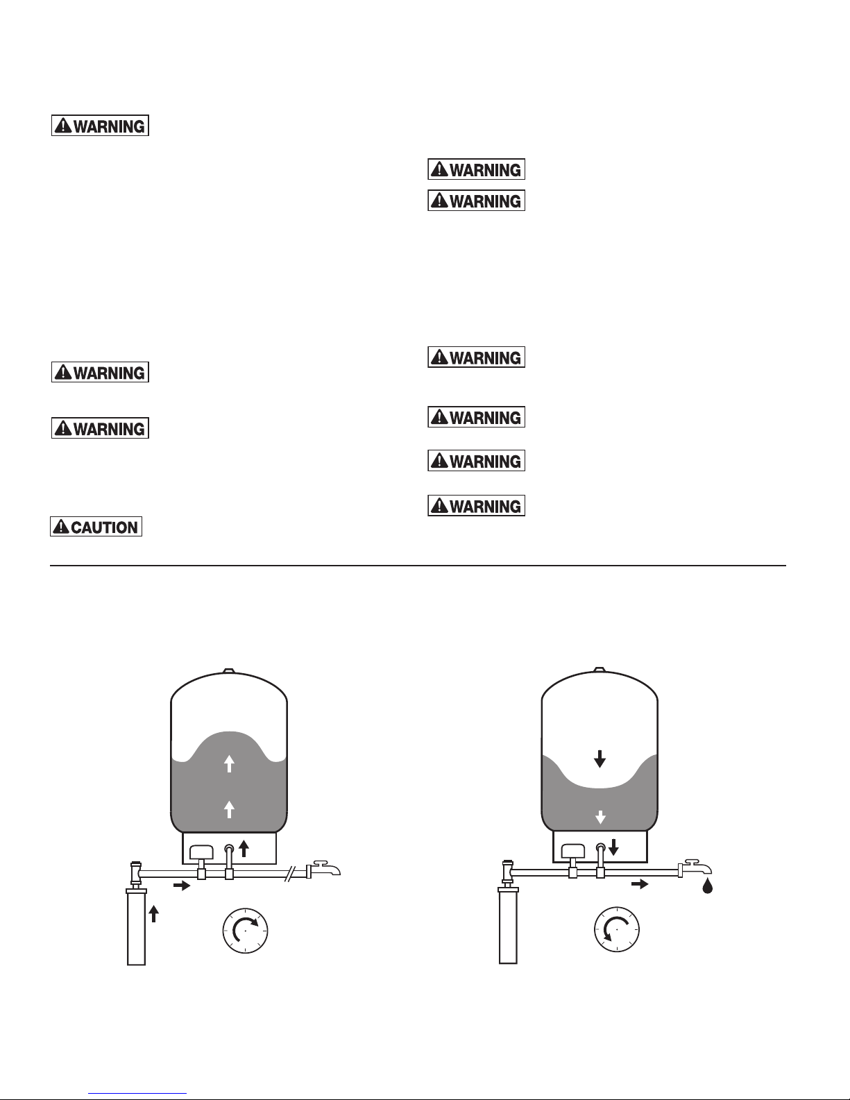
How a Well Tank Works
1. As the pump fills the tank with water, the air above the
diaphragm is compressed. This increases the pressure in the
tank and causes the pressure switch to turn off the pump.
Air
Water
Pressure
Switch
Fixture Closed
Pump
Pressure
2. When water is used, it is drawn from the tank and the pressure
inside the tank decreases. The reduced pressure starts the
pump and refills the tank.
Air
Water
Pressure
Switch
Fixture Open
Pump
Pressure
The amount of water delivered between pump cycles is called
drawdown. The larger the well tank, the greater the drawdown
capacity, the less the pump needs to run. This saves energy and
money, and extends pump life. Larger tank sizes also increase the
water storage volume to provide more consistent water pressure.
Page 3

Installation of In-Line Turbulator
The In-Line Turbulator water circulation device is designed to
circulate the water stored in your diaphragm well tank.
1. Inspect the In-Line Turbulator for any damage that may
have occurred during shipping. Insert the In-Line Turbulator
(Diagram 1) into the system connection of the expansion tank.
The Turbulator can only be inserted with the butt end out as
the locking tabs prevent it from being installed backwards.
Diagram 1.
Locking Tabs
2. Palm press the In-Line Turbulator (Diagram 2) until the unit
locking tabs butt up against the system connection.
Diagram 2.
3. Your diaphragm well tank is now ready to be installed
(Diagram 3).
Diagram 3.
™
Installation
System Connection
In-line Models:
WX-101 through WX-103: ¾" NPTM
WX-104 and WX-200: 1" NPTM
Vertical Stand Models:
WX-201 through WX-203: 1" NPTF
WX-205 through WX-350: 1¼" NPTF
Horizontal Models:
WX-102PS through WX-110PS: ¾" NPTM
WX-200PS, WX-202PS and WX-202H: 1" NPTM
Underground Models:
WX-200UG and WX-202UG: 1" NPTF
WX-250UG and WX-251UG: 1¼" NPTF
Pre Installation
The surface on which the Well-X-Trol is installed should be
capable of supporting its operating weight (including the weight
of water). The Well-X-Trol should be installed as close as
possible to the pressure switch. This will reduce the adverse
effects of added friction loss and differences in elevation
between Well-X-Trol and/or water supply main and switch.
Adjacent to pump: This is the location chosen most often. The
Well-X-Trol tank can be used whether pumps are above or
below the surface. In either case, it protects the pump by
reducing surge, dampening pressure spikes, offering a point of
pressure control, and providing minimum run time. This location
also permits all equipment to be placed in an area that’s both
serviceable and secure.
At the end of long pipe runs: The Well-X-Trol tank can be
positioned at the end of a long run of pipe so it can provide rapid
system response and adequate protection. When this location is
chosen, the pressure switch should either be relocated with the
Well-X-Trol tank or the setting should be adjusted to compensate
for any line pressure drop.
DO NOT LOCATE IN AN AREA WHERE
LEAKAGE OF THE TANK OR CONNECTIONS
COULD CAUSE PROPERTY DAMAGE TO THE AREA ADJACENT TO
THE APPLIANCE OR TO LOWER FLOORS.
Locking Tabs
1. Remove protective air valve cap.
2. Check pre-charge pressure.
3. Release or add air as necessary to set the pre-charge
pressure 2 psig below the pressure switch pump cut-in
setting. (Example, 38 psig precharge for a 40/60 pressure.)
4. Replace protective air valve cap.
Page 4

Suggested Piping Diagrams
In-line Models:
WELL-X-TROL
JET
PUMP
Underground Models:
RELIEF VALVE
BUILDING FOUNDATION
FROST LINE
Horizontal Models:
RELIEF VALV E
WELL-X-TROL
POSSIBLE PRESSURE
SWITCH LOCATION
PRESSURE TANK LOCATION
STICKER SUPPLIED WITH
EACH UNIT
WELL
N
W
(O)
PRESSURE TANK LOCATION,
FOR EXAMPLE
E
110
S
WELL-X-TROL
ROCK FREE
COARSE SAND
PUMP
All Well-X-Trol Underground Tanks are designed for direct
burial and must be installed in the vertical position only. To
eliminate danger of freezing, tank should be buried below the
frost line.
The following steps should be taken when installing a Well-X-Trol
Underground Tank:
1. Make sure that the tank will be buried below the frost line and
above the water table.
2. Remove plastic bag and check tank precharge. Factory
precharge is 38 psig. Replace air stem cap securely. Follow
adjusting precharge procedure.
TO HOUSE
"UG"
3. Important: Install tank on firm rock-free earth.
4. The water lines from the pump to the tank and switch location
should be the same size to prevent switch cycling.
5. Check the system for performance and inspect for leaks.
6. Important: Backfill hole with sand. Firmly tamp fill to prevent
settling. Failure to do so will shorten tank life.
7. Fill out pressure tank location sticker and affix to power panel
or other visible surface so tank can be easily located at a
later time.
Page 5

Suggested Piping Diagrams (cont.)
Vertical Models:
WELL-X-TROL
UNIVERSAL
PUMP STAND 398096
WELL-X-TROL
WELL-X-TROL
Page 6

Start Up
Fine Tuning Procedures
1. Restore power and pressurize system until pump cuts off.
2. Open one or more fixtures to reduce pressure and initiate a
pump cycle.
3. Check operation. Make adjustments only when the tank is
empty of water and the system is off.
Figure 2
Pressure Adjustment:
• Clockwise to increase
cut-out pressure.
• Counter-clockise to decrease
cut-out pressure.
Adjusting Precharge After Installation
Step 1. Drain tank of all water. Check precharge pressure in the
Well-X-Trol Tank.
Step 2. Release or add air as necessary to set the precharge
pressure 2 psig below the pressure switch pump cut-in setting.
Maintenance
A licensed professional should check the complete system,
including the Well-X-Trol, yearly and more frequently as the
system ages.
Warranty
WX Models: Seven (7) Year Limited Warranty
Visit www.amtrol.com for complete warranty details and to
register the serial number of your well tank.
1400 Division Road, West Warwick, RI USA 02893
T: 800.426.8765 www.amtrol.com
© 2019 Worthington Industries, Inc. Part #: 9016-868 MC10185 (02/19)
 Loading...