

Page 1
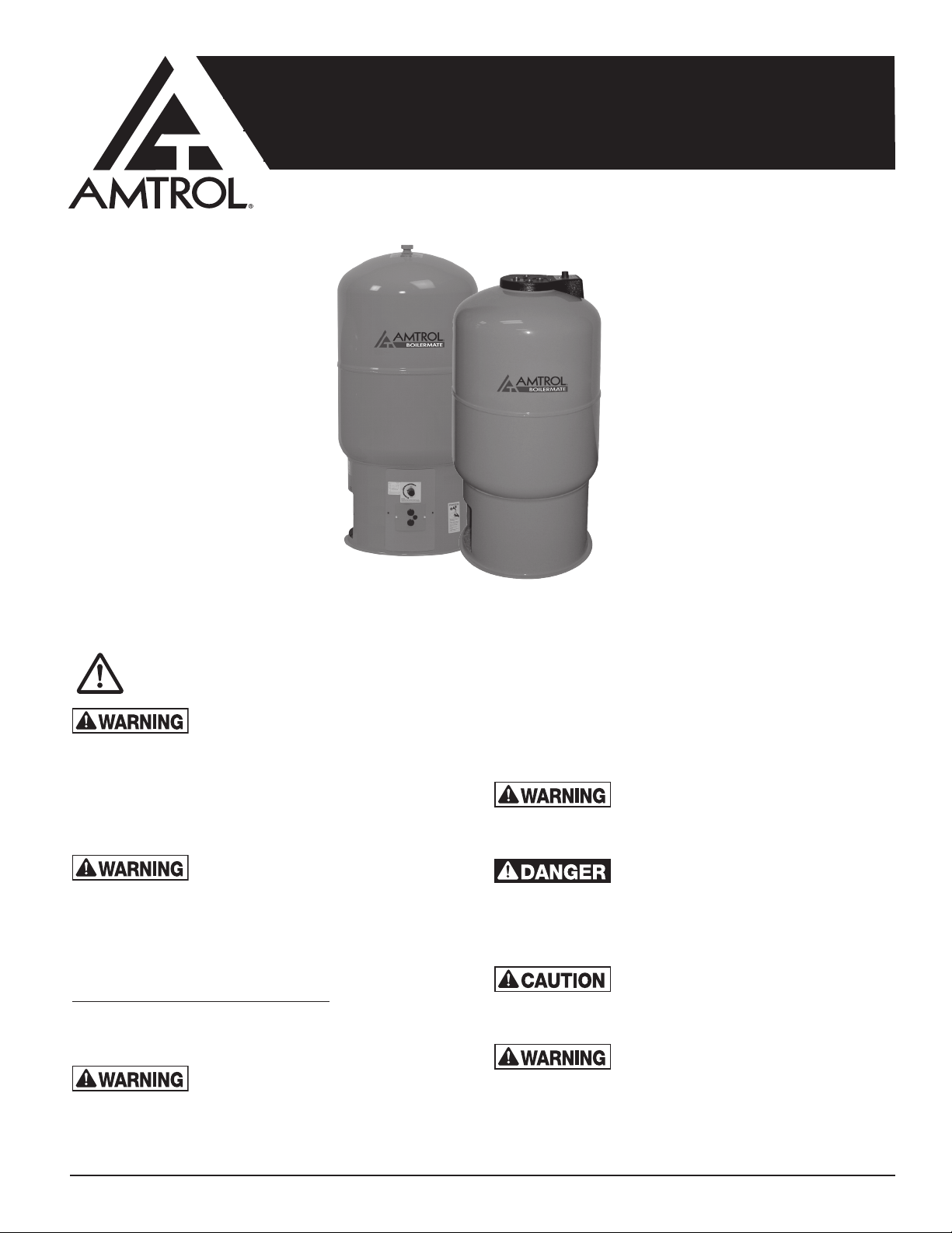
BOILERMATE
INDIRECT-FIRED WATER HEATERS
INSTALLATION & OPERATION INSTRUCTIONS
Models WH (Mechanical Control & Digital Control)
Models CH (Mechanical Control)
NOTE: A properly sized thermal
expansion tank is required and should
be installed in accordance with the
product installation manual.
NOTE: The thermostat is adjusted to
120°F when shipped from the factory.
®
NOTE: Inspect for shipping damage and notify freight carrier or store where purchased immediately if damage is present. To avoid risk of personal
injury and property damage, if the product appears to be malfunctioning or shows signs of corrosion, call a qualified professional immediately. Current
copies of the Product manual can be viewed at www.amtrol.com. Use proper safety equipment when installing.
THIS IS THE SAFETY ALERT SYMBOL. IT IS USED TO ALERT YOU TO POTENTIAL PERSONAL INJURY AND OTHER
HAZARDS. OBEY ALL SAFETY MESSAGES THAT FOLLOW THIS SYMBOL TO REDUCE THE RISK OF PERSONAL
INJURY AS WELL AS PROPERTY DAMAGE.
READ CAREFULLY THE PRODUCT
INSTALLATION & OPERATION INSTRUCTIONS.
FAILURE TO FOLLOW THE INSTRUCTIONS AND WARNINGS IN THE
MANUAL MAY RESULT IN SERIOUS OR FATAL INJURY AND/OR
PROPERTY DAMAGE, AND WILL VOID THE PRODUCT WARRANTY.
THIS PRODUCT MUST BE INSTALLED BY A QUALIFIED
PROFESSIONAL. FOLLOW ALL APPLICABLE LOCAL AND STATE
CODES AND REGULATIONS, IN THE ABSENCE OF SUCH CODES,
FOLLOW THE CURRENT EDITIONS OF THE NATIONAL PLUMBING
CODE AND NATIONAL ELECTRIC CODE, AS APPLICABLE.
This Product, like most Products under pressure,
may over time corrode, weaken and burst or
explode, causing serious or fatal injury, leaking or flooding and/or property
damage. To minimize risk, a licensed professional must install and
periodically inspect and service the Product. A drip pan connected to an
adequate drain must be installed if leaking or flooding could cause property
damage. Do not locate in an area where leaking could cause property
damage to the area adjacent to the appliance or to lower floors of
the structure.
CALIFORNIA PROPOSITION 65 WARNING! This product contains a
chemical known by the State of California to cause cancer and to cause
birth defects or other reproductive harm. (California Installer/Contractor California law requires that this notice be given to consumer/end user of
this product.) For more information: www.amtrol.com/prop65.html
A relief valve must be installed to prevent pressure in
excess of local code requirement or maximum
working pressure designated in the Product Manual, whichever is less. At
least once every 3 years or if discharge is present, a licensed contractor
should inspect the temperature and pressure relief valve and replace if
corrosion is evident or the valve does not function.
FAILURE TO INSPECT THIS VALVE AS DIRECTED COULD RESULT
IN UNSAFE TEMPERATURE OR PRESSURE BUILD-UP WHICH
CAN RESULT IN PRODUCT FAILURE, SERIOUS INJURY OR
DEATH AND/OR SEVERE PROPERTY DAMAGE AND VOID THE
PRODUCT WARRANTY.
Chlorine Aggressive Water: The water quality can
significantly influence the life of this Product. You
should test for corrosive elements, acidity, total solids and other relevant
contaminants, including chlorine and treat your water appropriately to
insure satisfactory performance and prevent premature failure.
EXPLOSION HAZARD. The pressure of the heat
transfer medium must be limited to a maximum of 30
psig by an approved safety or relief valve on your boiler. The water heater
pressure must be limited to 150 psig maximum by the installation of a
temperature and pressure relief valve (included). The relief tube must be
plumbed to a suitable drain per code. No reducing coupling or other
restriction may be placed in this line.
The heat transfer medium must be water or other
nontoxic fluid having a toxicity rating or class of 1, as
listed in Clinical Toxicology of Commercial Products, 5th edition. The
pressure of the heat transfer medium must be limited to 30 PSIG by an
approved safety or relief valve.
Do not expose Product to freezing temperatures or
temperatures in excess of the maximum rated
operating temperature.
Page 2
SCALDING HAZARD. If the water temperature is
over 120°F, household members can suffer serious
or fatal scalding and painful and permanent injury.
• The Consumer Products Safety Commission recommends an initial
setting of 120°F, but advised that a slower response time of infants,
aged, disabled and other persons increases the scalding hazard and
may require lower settings.
• Always check the water temperature before use, including washing,
bathing or showering.
• Temperature limiting valves are available from your plumbing supplier.
A check valve must be installed in the boiler return line to prevent
gravity flow through the heat exchanger. This can cause overheating
and result in serious or fatal scalding.
SCALDING HAZARD. If the thermostat is not
working properly or if this product is not installed in
accordance with the manual, water temperature can reach excessive
levels that may cause serious or fatal scalding. After installation and any
servicing of the unit, verify that the thermostat is working and firmly
inserted in the thermostat well by following the thermostat testing
instructions in the manual.
Failure to use the correct replacement parts may
make your product unsafe.
In limited circumstances, space heating can be lost
in the home with unit utilizing priority mode. Any
demand for space heating is postponed until the water heater has
reached its set temperature. This delay in supplying the space heating
zones is usually not noticed by the inhabitants of the living spaces.
However, in the event of certain malfunctions such as circulator or
thermostat failure, space heating could be delayed indefinitely. If
undetected and uncorrected, freezing damage to piping could result.
If a steel hydropneumatic tank is in place, replace it
with a properly sized diaphragm expansion tank.
Otherwise, significant heat transfer problems can occur by causing air to
be trapped in the heat exchanger. If the boiler system has a diaphragm
expansion tank and the boiler temperatures are being changed, resize the
expansion tank.
If installing on city water supply, a properly sized
thermal expansion tank is required with the water
heater and should be installed as set fo rth in the product installation
manual. Contact your water supplier or local plumbing inspector for
additional information.
Prevent pressure build-up in any existing internal
tankless coil. Do not plug incoming or outgoing
tappings in the internal tankless coil plate. Leave the coil in the boiler and
leave system connections open to prevent pressure build-up.
Electrocution hazard. The water heater must be
electrically grounded in accordance with local codes
or, in the absence of local codes, with the National Electrical Code, ANSI/
NFPA 70. Electrical supply must come from the boiler side of boiler’s
emergency shut-off switch in order to prevent unsafe boiler operation.
If not installed by the boiler manufacturer, install a
low water cut-off or pressure reducing valve on your
boiler so that leaking will not result in a dry boiler which if the boiler
continues to fire, will cause an explosion hazard.
This unit must be installed as a separate heating
zone. Do not connect this unit to an existing heating
zone or feed boiler water directly through the coil as dangerous
over-heating will result.
Do not drain this appliance before shutting off the
supply valve and opening the relief valve or
another downstream fixture, as it will damage this unit. A vacuum breaker
should be installed to avoid damaging the liner. Damage to the unit and
leakage can occur if a vacuum breaker is not installed.
As in all plumbing products and water storage
vessels, bacteria can grow in this Product, especially
during times of non-use. Consult your local plumbing professional
regarding any steps you may wish to take to safely disinfect your home’s
plumbing system.
USE GLYCOL ONLY WITH DOUBLE- WALLED
HEAT EXCHANGER MODELS. Glycol is a
poisonous substance. To avoid seepage or leakage of glycol to
surfaces where humans or animals can ingest it, use glycol only in
double-walled units, so that any leaks will most likely be released to
the atmosphere. However, a leak to a surface area may still occur,
so any use of glycol must be monitored closely and humans and
animals should be protected from contact with the unit.
Do not connect the water heater domestic
supply with baseboard or other space heating
units or elements. Any contaminants in the baseboard units will
contaminate the potable water in the water heater and also adversely
affect its performance.
Do not drill, puncture or otherwise penetrate
the steel outer tank shell. Do not screw pipe
hangers or other hardware into the exterior of the tank.
-2-
Page 3
PLEASE READ THE FOLLOWING INSTRUCTIONS CAREFULLY
IMPORTANT GENERAL SAFETY INFORMATION -
ADDITIONAL SPECIFIC SAFETY ALERTS APPEAR IN THE FOLLOWING INSTRUCTIONS.
Pre-Installation
• THIS PRODUCT MUST BE INSTALLED AND MAINTAINED BY
A LICENSED PROFESSIONAL PLUMBER, ELECTRICIAN, AS
APPLICABLE. IN ADDITION TO THE INSTRUCTIONS IN THIS
MANUAL, FOLLOW ALL APPLICABLE LOCAL AND STATE
CODES INCLUDING MA CMR 248 OR IN THE ABSENCE OF SUCH
CODES, THE CURRENT EDITIONS OF THE NATIONAL PLUMBING
CODE AND THE NATIONAL ELECTRIC CODE.
• DRIP PAN AND DRAIN: This appliance should not be installed in
an area where leakage of the tank or connections can result in
damage to the area adjacent to the appliance or to lower floors of
the structure. When such locations cannot be avoided, a suitable
drain pan, adequately drained and kept clear, must be installed
under the appliance.
• CAUTION: Determine whether your water is corrosive or acidic,
and that there are no suspended solids, toxic or other substances
or abnormally high chlorine levels in the water that could damage
or affect the water heater or the rest of your plumbing system.
• Wiring Options. Select either a Non-Priority or Priority System:
Two options are available when wiring the controls of the water heater
in the space heating system (boiler and distribution elements).
1. Non-Priority System - The controls of the water heater must be wired
as a separate heating zone with a standard zone valve or a separate
circulator dedicated to the water heater “zone”.
NOTICE: In this non-priority option, the water heater will be supplied
just as another zone. This means that if all space heating zones call for
hot boiler water at the same time, the water heater may not be supplied
with enough hot boiler water to “recover” adequately. The delivery of
domestic hot water will be diminished. In many, but not all cases,
this is not a problem because the routine oversizing of boiler output is
adequate for both loads.
2. Priority System - Under this wiring option the water heater will be
supplied before space heating.
In limited circumstances, space heating can
be lost in the home in this priority mode. Any
demand for space heating is postponed until the water heater has
reached its set temperature. This delay in supplying the space
heating zones is usually not noticed by the inhabitants of the
living spaces. However, in the event of certain malfunctions such
as circulator or thermostat failure, space heating could be delayed
indefinitely. If undetected and uncorrected, freezing damage to
piping could result.
• Select Circulator versus Zone Valve
The flow of hot boiler water to the water heater can be controlled with
either a motorized zone valve or a circulator.
1. Separate circulator. The recommended way to provide adequate
flow through the water heater heat exchanger is to use a separate
dedicated circulator. This option may be used even though the heating
system utilizes zone valves.
2. Zone valve. If a zone valve is to be used, a flow rate of 3 to 5 gpm with
all zones in use is required. A full-port zone valve should be used.
• All installations require a low-water cut-off or automatic fill valve on your
boiler system to reduce the risk of boiler water loss.
• Steam boiler installations require a low-water cut-off which is also
required by most codes.
• Installation of a vacuum breaker is required to prevent damage to the
water heater when drained. There must be no valves installed between
the vacuum breaker and water heater.
Required Components
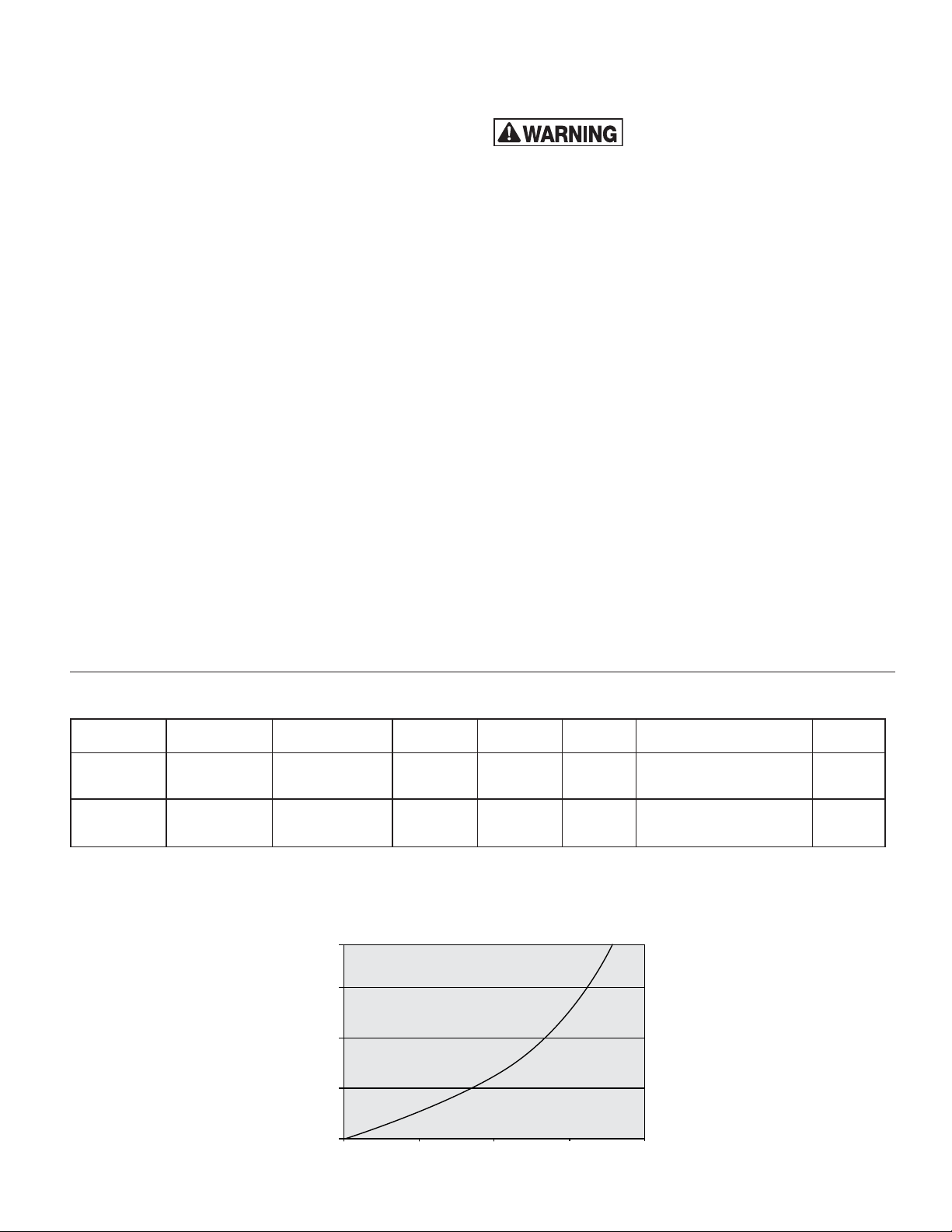
MODEL CIRCULATOR ZONE VALVE*
WH SERIES
CH SERIES
*IF CIRCULATOR IS NOT USED.
ALL INSTALLATIONS REQUIRE AN ADEQUATE AMOUNT OF TEFLON® SEALING TAPE OR PIPE DOPE FOR THREADED JOINTS.
4 GPM
@ 6 FT
4 GPM
@ 6 FT
3/4” Full Port or
1” STD
3/4” Full Port or
1” STD
SHUTOFF
VALV E
4 1 Included 41 Gal. Models: 2 Gal. Included
4 1 Included
Heat Exchanger Pressure Drop
Use this chart to select the proper circulator for your BOILERMATE®.
20
15
10
5
Pressure Drop (Ft)
0
0 2 4 6 8
VACUUM
BREAKER
Flow (GPM)
RELIEF
VALV E
THERMAL EXPANSION
TANK
41 Gal. Models: 2 Gal.
80 Gal. Models: 4.4 Gal.
DRAIN
Included
-3-
Page 4
RETURN
BOILER
SUPPL
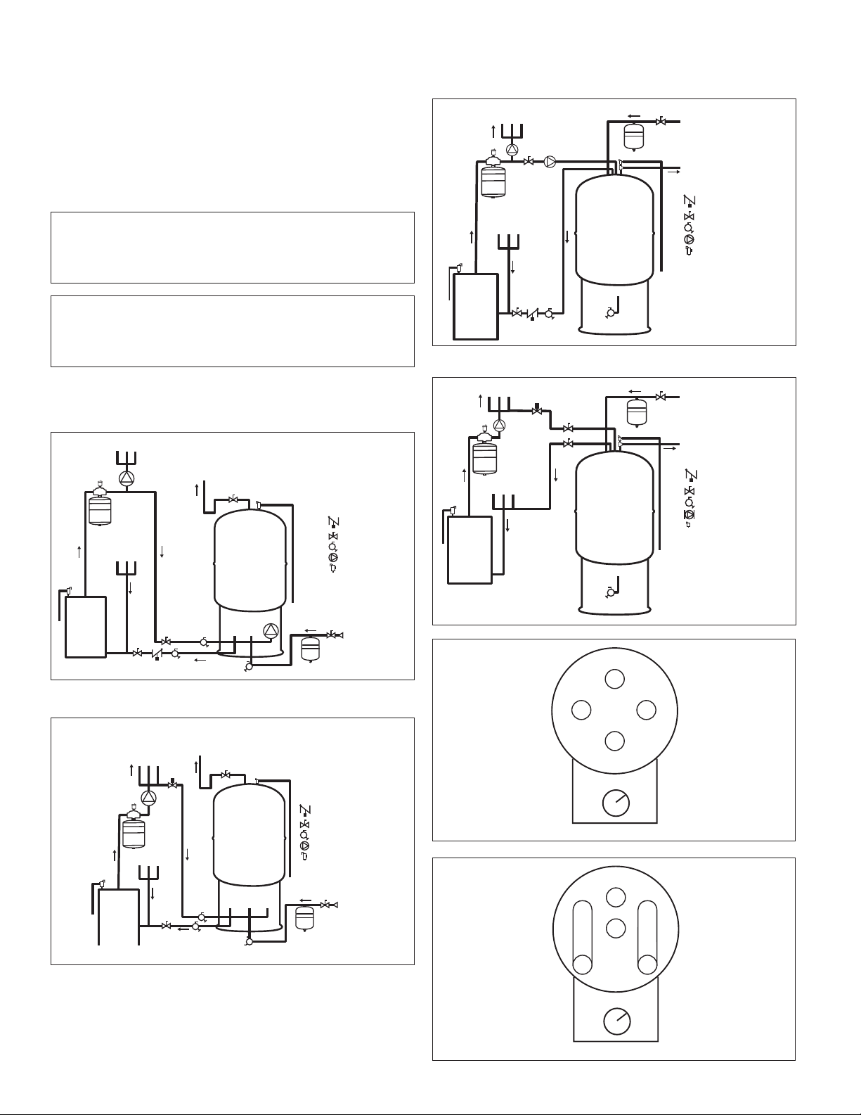
Installation - Domestic Water Piping
Hot Water Supply
Supply
Zone Returns
System Pump
Zone Valve
Heating Zones
Boiler
Supply
Boiler
Return
Cold Water Supply
Hot Water Supply
Therm-X-Trol
®
Blowdown Tube
Tee
EXTROL
®
Expansion Tank
and Air Purger
Weighted Flow Check
Shutoff Valve
Circulator
Relief Valve
Drain or Purge Valve
Boiler
BOILERMATE
®
CH Models
1.
Connect the cold water supply to the connection labeled COLD WATER.
2. Connect the HOT WATER piping to the domestic hot water system.
3. When all domestic water piping is complete, open the cold water supply
and allow some water to enter the tank. Look and listen for signs of
leaks and repair as necessary before continuing.
4. Install the temperature & pressure relief valve and plumb a blow down
tube to within 6" above a floor drain or as directed by plumbing code.
Clearance From Combustible Surfaces
LEFT SIDE ........... 1"
RIGHT SIDE.......... 1"
TOP ................9"
REAR ...............1"
FLOOR ..............0"
FRONT ..............1"
Clearance for Servicing
LEFT............... 12"
RIGHT ............. 12"
HEAD ROOM .......36"
REAR ..............1"
FRONT ............. 30"
WH Models
PIPING USING SEPARATE CIRCULATOR PUMP (RECOMMENDED)
Hot Water Supply
PIPING USING DEDICATED CIRCULATOR PUMP (RECOMMENDED)
Supply
Boiler
To Heating Zones
EXTROL
Expansion Tank
and Air Purger
Zone Returns
Boiler
Supply
BOILERMATE
Tee
®
Boiler
®
Return
Therm-X-Trol
Blowdown Tube
Cold Water Supply
®
Hot Water Supply
Weighted Flow Check
Shutoff Valve
Drain or Purge Valve
Circulator
Relief Valve
PIPING USING ZONE VALVE WITH EXISTING HEATING SYSTEM CIRCULATOR
BOILERMATE
Boiler
Return
CWS
Blowdown Tube
®
Boiler
Supply
Therm-X-Trol
Cold Water Supply
®
Supply
Boiler
EXTROL
Expansion Tank
and Air Purger
Zone Returns
®
Heat Trap
PIPING USING ZONE VALVE WITH EXISTING HEATING SYSTEM CIRCULATOR
BoilerMate®
Zone Valve
EXTROL
Expansion Tank
and Air Purger
Hot Water Supply
Heat Trap
®
BOILERMATE
Boiler
Return
Blowdown Tube
®
Boiler
CWS
Supply
Therm-X-Trol
Weighted Flow Check
Shutoff Valve
Drain or Purge Valve
Circulator
Relief Valve
Cold Water Supply
®
To Heating Zones
Supply
Boiler
Zone Returns
Weighted Flow Check
Shutoff Valve
Drain or Purge Valve
Circulator
Relief Valve
BOILER SUPPLY
COLD
SUPPLY
HOT
OUTLET
BOILER RETURN
AQUASTAT
Single Wall Models: CH-41Z / CH-80Z
HOT OUTLET
COLD
SUPPLY
Y
BOILER
AQUASTAT
Double Wall Models: CH-41ZDW / CH-80ZDW
-4-
Page 5
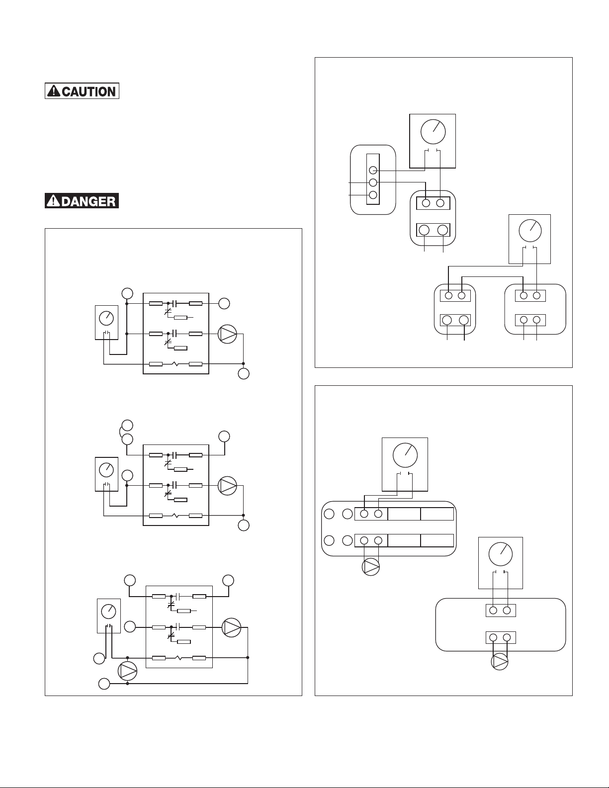
Installation - Boiler Piping
1. Plumb the circulator or zone valve on the BOILER SUPPLY line.
2. Pipe the BOILER RETURN connection to the boiler return line.
Be sure the return line is NOT plumbed to the
suction side of any heating circulators. This
may require moving the heating circulator off the boiler tapping on
packaged boilers. Failure to do so will result in overheating and
tank damage when the heating system is in operation.
3. Install a weighted flow check on the boiler return line. This is not
necessary on systems utilizing a zone valve to control the water
heater temperature.
4. After completing the boiler piping, slowly open the boiler fill valve
and pressurize the water heater loop. Check for leaks and repair as
necessary. Proceed to the appropriate wiring section in this manual.
EXPLOSION HAZARD. Do not install to a high
pressure steam boiler (greater than 15 psig).
Mechanical Aquastat
Typical Oil Burner (Non-Priority)
HONEYWELL
R4222D 1013
OR EQUIVALENT
L1
AQUASTAT
Typical Gas Valves (Non-Priority)
DPDT RELAY
31
2
4 6
5
COIL
WHEN NO “ZR” TERMINAL IS AVAILABLE
GO TO THE SUPPLY SIDE OF THE HI LIMIT
BOILERMATE
CIRCULATOR
ZR
L2
END
SWITCH
ZONE VALVE
Zone Valves
3-Wire
AQUASTAT
24VAC
TRANSFORMER
L1L2
TRANSFORMER
L1L2
Other Applications
4-Wire
24VAC
AQUASTAT
ZONE VALVE
MOTOR
END
SWITCH
HONEYWELL
R4222D 1013
OR EQUIVALENT
DPDT RELAY
2
4 6
5
COIL
31
B
BOILERMATE
CIRCULATOR
L2
AQUASTAT
W
Z
L1
24V Thermostat Input (Priority)
HONEYWELL
R4222D 1013
OR EQUIVALENT
AQUASTAT
L1
L2
T
C1
DPDT RELAY
2
4 6
5
COIL
31
T
BOILERMATE
CIRCULATOR
Note: if your application is not shown,
contact AMTROL Technical Support at 401.535.1216.
TO BOILER
Multi-Zone Control
L1L2
DHW ZONE
XX
BOILERMATE
CIRCULATOR
OR ZONE VALVE
AQUASTAT
Boiler Control Input
AQUASTAT
DHW ZONE
BOILERMATE
CIRCULATOR
OR ZONE VALVE
-5-
Page 6
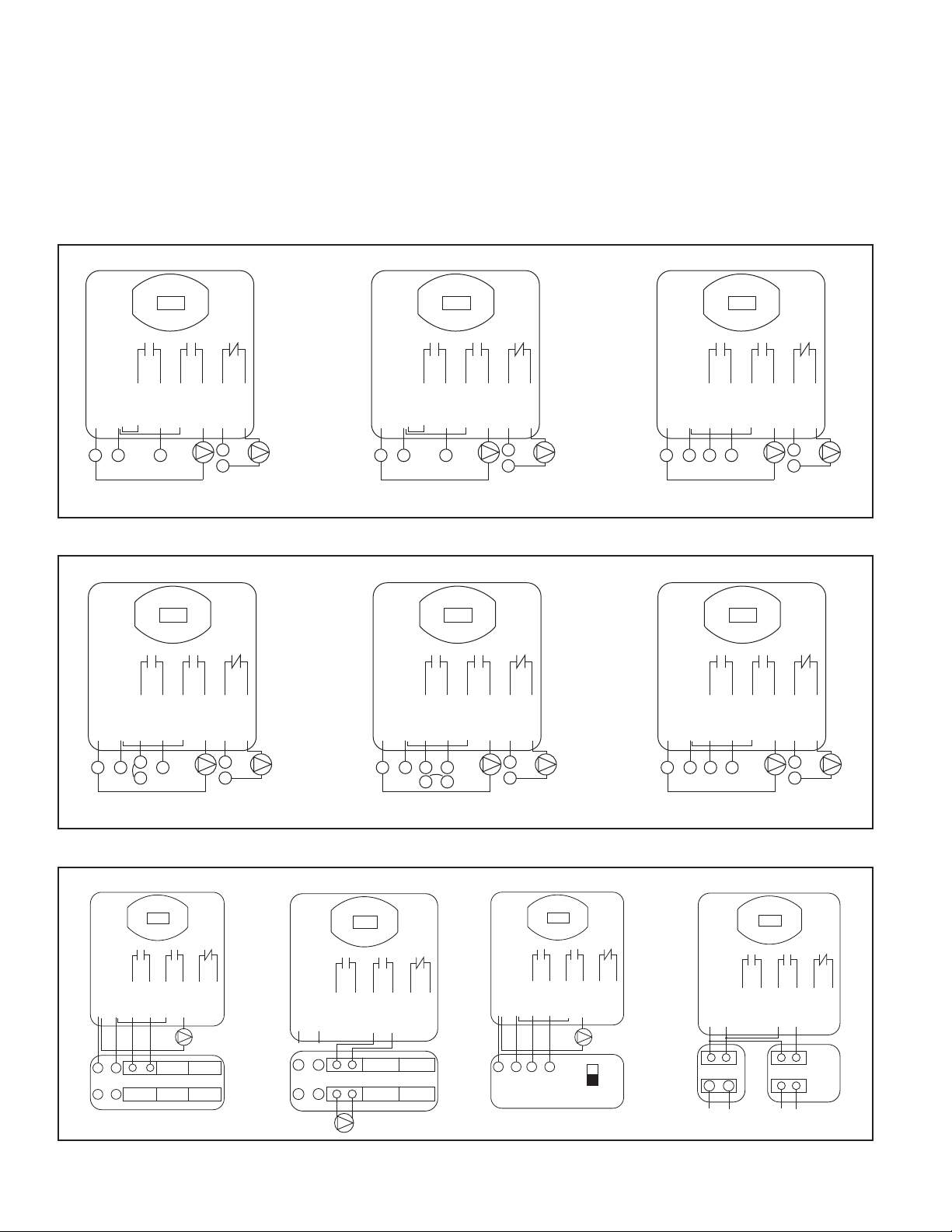
Installation - Digital Control Wiring
1. Ensure the control installation is within the following application and
operating parameters:
• Ambient temperature from 38° to 125°F.
• Relative humidity ranging from 20% to 90% (non-condensing).
• Boiler load rating up to 15A resistive, 1/4hp inductive @ 120VAC.
• Circulator load rating up to 15A, 1/4hp inductive @ 120VAC.
• Space heating load rating up to 8A @ 120VAC.
Oil Burner Controls
ZR Input Terminal
POWER BURNER PUMP PRIORITY
ORANGE
WHITE
L2
BLACK
ORANGE
L1 ZR
BLUE
BLUE
BOILERMATE
CIRCULATOR
VIOLET
C1
C2
CIRCULATOR
VIOLET
HEATING
High Limit (B Terminal)
POWER BURNER PUMP PRIORITY
ORANGE
BLACK
ORANGE
WHITE
L1 B
L2
Gas Valve Controls
NOTE: Line-voltage and safety-circuit wiring that is external to the
water heater jacket when all panels are in place, and which is part of
the appliance, shall be protected by metal conduit, metal-clad cable or
raceways. Thermoelectric wiring shall be exempt from this provision.
NOTE: Strain relief shall be provided for all conductors leaving an
enclosure. For low-voltage wiring, strain relief at the point of exit from an
enclosure is not necessary if, by wire location or support, protection is
provided against accidental strain.
Triple-Aquastat
POWER BURNER PUMP PRIORITY
BLUE
BLUE
BOILERMATE
CIRCULATOR
VIOLET
C1
C2
CIRCULATOR
VIOLET
HEATING
L2
WHITE
L1 BR
BLACK
ORANGE
ORANGE
BLUE
BOILERMATE
CIRCULATOR
BLUE
VIOLET
C1
C2
CIRCULATOR
VIOLET
HEATING
24 Volt
POWER BURNER PUMP PRIORITY
ORANGE
WHITE
L2
BLACK
ORANGE
Z
L1 B
W
BLUE
BLUE
BOILERMATE
CIRCULATOR
Other Applications
Multi-Zone Control: Using Post Purge
POWER BURNER PUMP PRIORITY
ORANGE
WHITE
TO BOILER
BLACK
L1L2
XX
ORANGE
DHW ZONE
BLUE
BLUE
VIOLET
BOILERMATE
CIRCULATOR
VIOLET
C1
C2
VIOLET
VIOLET
HEATING
CIRCULATOR
POWER BURNER PUMP PRIORITY
BLACK
WHITE
L1 BB2
L2
Multi-Zone Control: No Post Purge
POWER BURNER PUMP PRIORITY
ORANGE
WHITE
24 OR 120VAC
TO BOILER
BLACK
L1L2
XX
ORANGE
DHW ZONE
BLUE
BLUE
BOILERMATE
CIRCULATOR
OR ZONE VALVE
Z W
VIOLET
Millivolt
ORANGE
VIOLET
ORANGE
BLUE
BLUE
BOILERMATE
CIRCULATOR
VIOLET
VIOLET
C1
C2
HEATING
CIRCULATOR
Outdoor Reset/Automatic Temperature Control
POWER BURNER PUMP PRIORITY
BLACK
ORANGE
WHITE
L1 ZC ZRL2
ORANGE
BLUE
BLUE
ZONE/INDRIECT SWITCH
(IF EQUIPPED)
SELECT “INDIRECT”
VIOLET
VIOLET
BOILERMATE
CIRCULATOR
Z
I
Self-Generating
POWER BURNER PUMP PRIORITY
ORANGE
BLACK
ORANGE
WHITE
L1 BB2
L2
POWER BURNER PUMP PRIORITY
®
24VAC
TRANSFORMER
4-Wire Zone Valve
BLACK
WHITE
L1L2
BLUE
BOILERMATE
CIRCULATOR
ORANGE
BLUE
ORANGE
C1
C2
BLUE
ZONE VALVE
VIOLET
VIOLET
HEATING
CIRCULATOR
BLUE
VIOLET
MOTOR
END
SWITCH
VIOLET
Note: if your application is not shown, contact AMTROL Technical Support at 401.535.1216.
-6-
Page 7
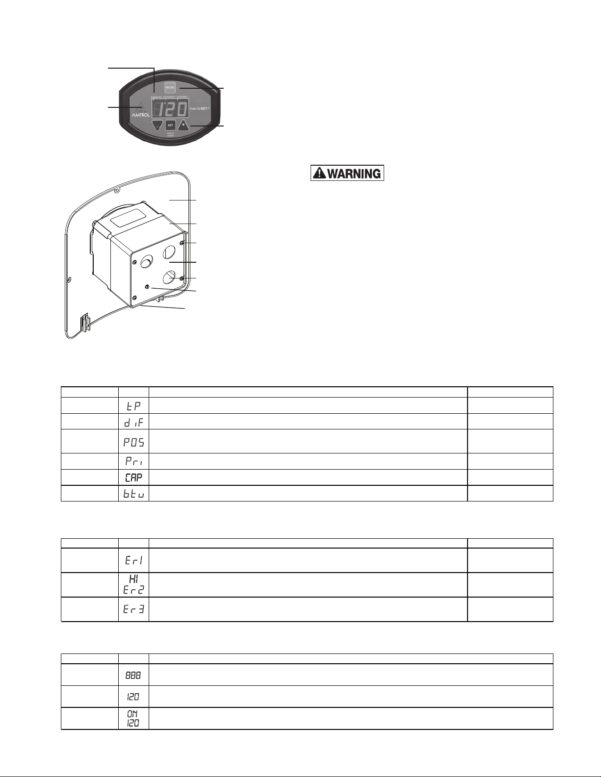
Installation - Digital Control Set-Up
Mode
Indicators
LED
Display
Front Panel
Control
Screws (4)
Wiring Cover
Conduit Holes (3)
Ground Screw
Temperature
Sensor Plug
User
Modes
Installer
Settings
After wiring per the appropriate diagram in this manual, insert the white
temperature sensor (thermistor) plug into the receptacle at the base of
the digital control. Zone valves can be slow actuating. Therefore, the
zone valve sensor contains a built-in temperature offset to account for the
time it takes the zone valve to fully close. This results in potable water
temperature that is representative of the digital control temperature set
point. This is why it is important to install the correct sensor into the digital
control. See Page 3 for information regarding the selection of a circulator
or zone valve.
Temperature settings above 120° F can create a
scald hazard.
Settings To adjust, press and hold the SET button until the Temperature setting appears.
Cycle through settings by depressing the SET button and using the ▼ and ▲ buttons to change the settings.
Setting Code Description Range
Temperature
Differential Domestic hot water temperature drop before call for heat. Default is 10°F. 5,10
Post-Purge Early boiler shutoff prior to hot water setpoint. Circulator runs until setpoint. Default is 0°F.
Priority Temporarily cancels space heat to maxmize available energy for hot water. Default is 'n'. y/n
Capacity Water heater capacity; select appropriate size for proper operation. Default is 41 Gallons. 26,41,60,80,120
BTU Transfer Real-time BTU transfer estimate in 1000 BTU/Hr increments. Diagnostic readout only. 0-199MBH/Hr
Domestic hot water setpoint. Default is 120°F
90-150
*Available only when
Differential setting is 10.
0,4,8*
Diagnostic Error Codes Codes clear automatically when corrected or can be reset by interrupting power to the control for 5 seconds.
To silence an alarm, depress the ▼ on the keypad.
Error Code Description Potential Causes
Temp Sensor Temperature sensor (thermistor) fault.
Overheating Domestic hot water temperature has exceeded maximum setpoint.
Slow Heating Unit has taken over 60 minutes to reach hot water setpoint or cannot reach setpoint.
Sensor unplugged
Sensor damaged
Error in boiler plumbing
Zone valve stuck open
Leak in sensor well
Faulty equipment
Fouled heat exchanger
No fuel
Operating Indicators Water sensor temperature may be shown for 30 seconds by pressing
the ▲ button.
Indicator Code Description
Startup Test
Displayed briefly during intial powerup to test LED display segments.
Idle
Heating
Static numeric [setpoint] readout (factory default shown) indicates domestic hot water setpoint.
Alternating On and [Setpoint] is displayed during a heating cycle while the circulator pump contacts are closed.
-7-
Page 8
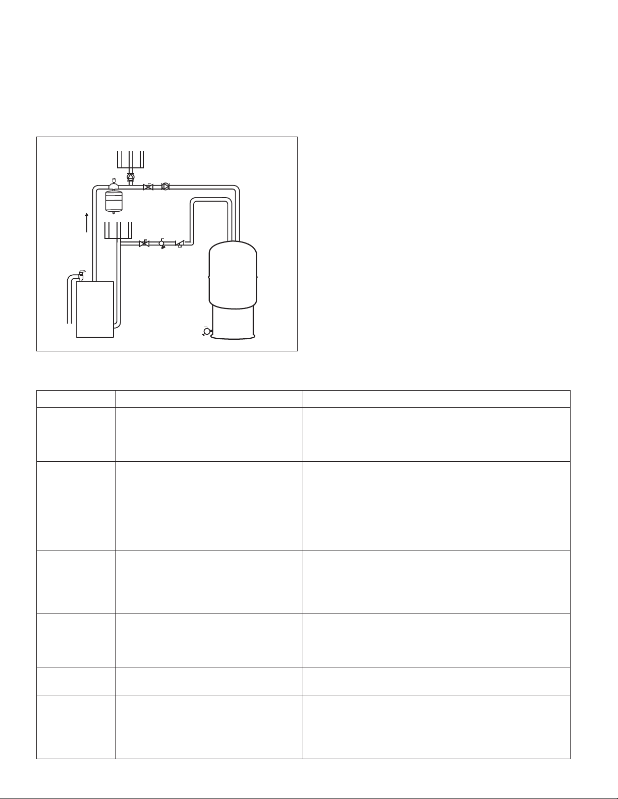
Start-Up Procedure
1. Purge Heat Exchanger: The heat exchanger should be free of large
air pockets to allow the circulator to operate properly. Using the
diagram below as a guide, isolate the boiler return line and flush the
loop until large air pockets are purged. After this, the air elimination
equipment will collect smaller air bubbles.
Purging Heat Exchanger (CH Series Shown)
2. Fill
Boiler
1. Close
Return
3. Purge
Air
2. Fill Tank: Open the hot water fixture furthest from the heater. Open
the cold water supply and allow the water to run until air stops
emerging. Air pockets may appear at any hot water fixture. This is
considered normal and will clear as hot water is used.
3. Start Heater: Turn power on to the unit. Digital Control models come
pre-set to 120°F for safety. Mechanical controls should have the knob
rotated to the 120°F mark. The circulator or zone valve should operate
and the boiler should start.
4. Check Operation: The water heater will begin to heat. Depending
upon the size of the water heater, output of the boiler and the space
heating load, the unit should typically reach set temperature within 15
to 60 minutes. If heating does not occur, consult the troubleshooting
section in this manual. Note: Large heaters coupled with small boilers
may exceed this time period upon initial startup.
5. Set Temperature: The control should be set to the minimum
temperature consistent with the user’s needs. This maximizes
efficiency and reduces scald potential.
MAINTENANCE
The water heater and system should be periodically checked by a
licensed professional at least annually and more often as system ages.
WARRANTY
CH and WH Models: Six (6) year limited warranty on heat exchanger and
tank assembly only. Visit www.amtrol.com for complete warranty details.
Troubleshooting
PROBLEM POSSIBLE CAUSES SOLUTION
No hot water 1. No power to unit
Insufficient hot water 1. Demand exceeds capacity
Water too hot 1. Improper plumbing
Relief valve dripping
or opening
2. Circulator air-bound
3. Faulty circulator or zone valve
4. Faulty control
5. Boiler inoperable
2. Temperature too low
3. Boiler lacks output for simultaneous heat & hot water
4. Fouled heat exchanger
5. Insufficient heat exchanger flow
2. Temperature set too high
3. Temperature sensor not fully inserted
4. Stuck zone valve
5. Flow check valve stuck open
1. Thermal expansion tank undersized or missing
2. Thermal expansion tank set improperly
3. City pressure too high
4. System over temperature
5. Faulty relief valve
1. Check circuit breaker, boiler emergency switch and boiler reset switch.
2. Purge air. Ensure circulator is on Boiler Supply. Check air vents.
3. Check circulator and zone valve. Repair or replace if necessary.
4. Check continuity. Switching circuits should close. If not, replace control.
5. Check boiler system. Boiler must operate to generate hot water.
1. Check sizing based on household size and boiler output.
2. Increase temperature setpoint.
3. Set up for priority. If problem persists add storage or increase tank size.
4. Check Boiler Supply/Boiler Return during cold startup. If difference is less
than 20°F, clean heat exchanger as outlined below. Install water treatment
equipment to prevent recurrence.
5. Check for undersized or faulty circulator, stuck or undersized zone valve.
Ensure all shutoff valves are open. Check for stuck flow check valve.
Purge boiler loop to remove air.
1. If Boiler Return is plumbed to the suction-side of a heating circulator,
overheating will occur when the home’s heat is on. Fix plumbing.
2. Reduce temperature setting.
3. Re-insert temperature sensor.
4. Repair or replace.
5. Clean, repair or replace.
1. Install the properly sized thermal expansion tank.
2. Ensure precharge air pressure matches static water pressure.
3. Install a Pressure Reducing Valve (PRV) if city pressure is over 80psi.
4. Determine cause of over temperature condition and correct problem.
5. Replace relief valve.
Discolored water
at faucet
Boiler will not operate
when calling for
hot water
1. Poor water quality
2. Sediment or suspended particles
1. Improper or loose wiring
2. Boiler high limit has been reached
3. Post Purge (POS) set too high
4. Problem with boiler system
1. Have water tested for contaminants.
2. Install sediment filter, purge unit more often to avoid future problems.
1. Check connections against wiring diagrams in this manual.
2. Boiler will periodically cycle on and off during operation.
3. Post Purge shuts the boiler off prior to reaching domestic setpoint. If set too
high, the boiler may not have enough energy to raise the water temperature
to setpoint. Reduce POS or set to 0 if the problem persists.
4. Have boiler diagnosed for proper operation.
-8-
Page 9
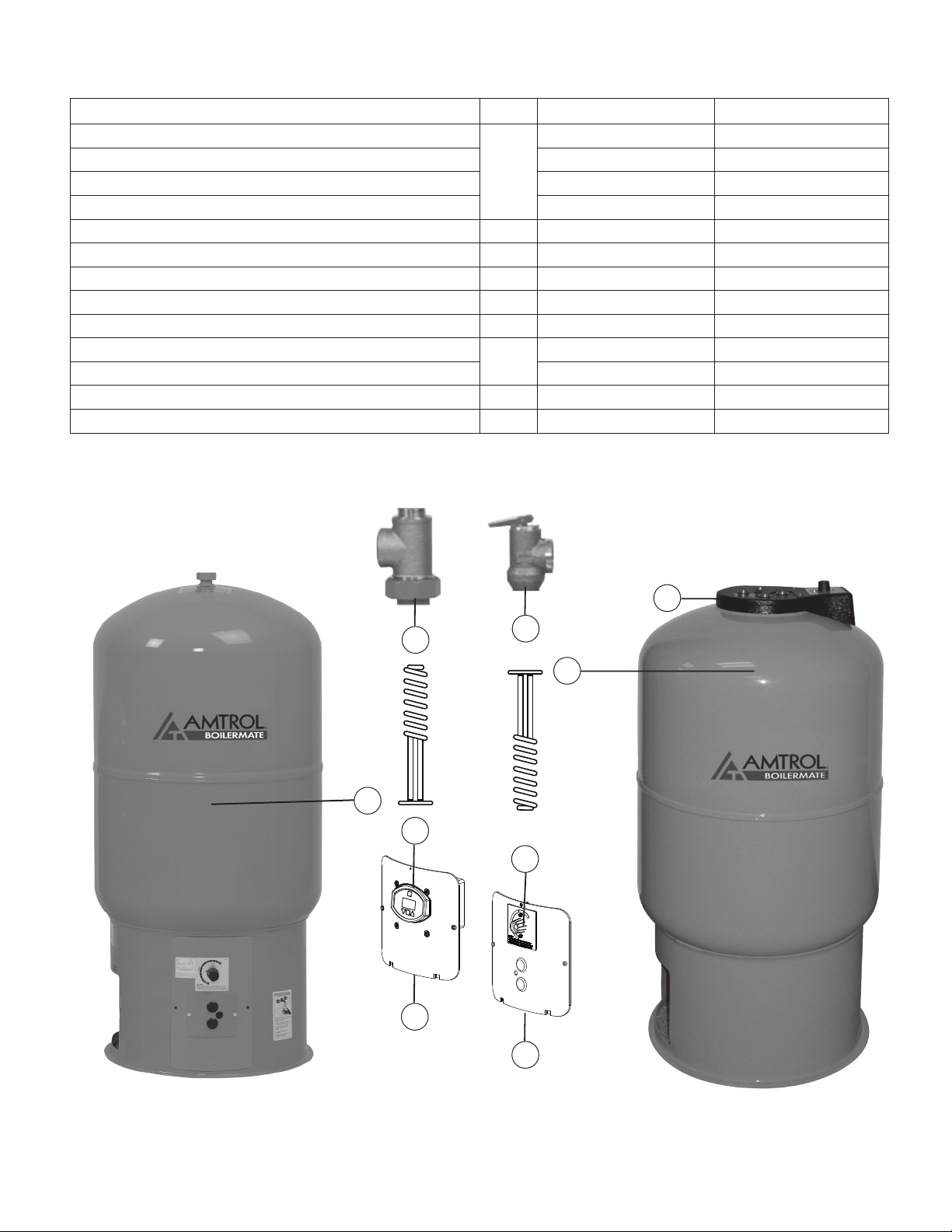
Replacement Parts
Description ID WH Series CH Series
Heat Exchanger Replacement, WH-41 Single Wall
Heat Exchanger Replacement, WH-41 Double Wall 2700-5002 -
Heat Exchanger Replacement, CH-41 Single Wall - 2703R003
Heat Exchanger Replacement, CH-80 Double Wall - 2702R002
Mounting Panel Only, Mechanical Control 2 2704R498 -
Mounting Panel Only, Digital Control 3 2704R525 -
Mechanical Temperature Control 4 2704-093
Digital Temperature Control w/Panel 5 940R101 -
Temperature Sensor, Digital Control - 2704-259 -
Cold Water Inlet Tube, CH-41
Cold Water Inlet Tube, CH-80 - 2702R001
T&P Safety Relief Valve 7 2700R1106 2700R1106
Top Outlet Union Tee 8 2700-635 -
1
6
2700-5000 -
- 2703R001
1
8
5
3
6
7
1
4
2
To obtain replacement parts, contact the installer or place of purchase.
Technical support is available by calling AMTROL at (401) 535-1216.
-9-
Page 10

-10-
Page 11

-11-
Page 12

1400 Division Road, West Warwick, RI USA 02893
T: 800.426.8765 F: 800.293.1519
© 2017 AMTROL Inc. 9040-586 (08/17)
www.amtrol.com
 Loading...