

I
Preface
©Copyright 2008
©
All Rights Reserved.
The information in this document is subject to change without pr ior notice in order to improve
reliability, design and function and does not represent a commitment on the part of the
manufacturer.
In no event will the manufacturer be liable for direct, indirect, special, incidental, or
consequential damages arising out of the use or inability to use the product or
documentation, even if advised of the possibility of such damages.
This document contains proprietary information protected by copyright. All rights are
reserved. No part of this manual may be reproduced by any mechanical, electronic, or other
means in any form without prior written permission of the manufacturer.
Safety Notices
1. Please read these safety instructions carefully.
2. All precautions and warnings on the equipmen t should be carefully noted.
3. Please disconnect the computer from the AC outlet before cleani ng.
4. Never pour any liquids into any ope nings or directl y onto the co mputer uni t. This
could result in fire or electrical shock.
5. Ensure the voltage range of the power outl et is betwee n 100V and 240V befo re
connecting the computer unit. Exceeding the maximum rated voltage may cause
damage to the AC adapter or to the computer. This could result in fire or
electrical shock.
6. Do not leave this equipment in a non-te mperature cont rolled envi ronment;
storage temperatures below 4°C (3 9°F) or above 35°C (95°F) ma y damage the
unit.
II
To reduce the risk of an electric shock, which could cause
personal injury, please follow all safety notices. The symbols shown are used in your
documentation and on your equipment to indicate safety hazards.
Lithium batteries can be dangerous. Danger of explosion if
battery is incorrectly replaced. Replace only with the same or equivalent type
recommended by the manufacturer. Dispose of used batteries according to the
manufacturer’s instructions.
Under no circumstances should the user attempt to
disassemble the power supply. The power supply has no user-replaceable parts. Inside
the power supply are hazardous voltages that can cause serious personal injury. A
defective power supply must be returned to your dealer.
Safety Notices for the Power Cord
This equipment has a 2 pins power cable. Replace the power cord if it becomes damaged.
Contact your dealer for an exact replacement.
In the U.S.A. and Canada, the power cord must be a UL-listed detachable power cord (in
Canada, CSA-certified).
2 pins power cable 18 AWG, 3-conductor
Provided with a molded-on cord connector body at the other end. The cord length must not
exceed 3 meters.
Outside the U.S.A. and Canada, the plug must be rated for 250 VAC, 2.5 amp min imum, and
must display an international agency approval marking. The cord must be suitable for use in
the end-user’s country. Consult your dealer or the local electrical authorities if you are
unsure of the type of power cord to use in your country. Voltage changes occur
automatically in the power supply.
Notice of EMC Compliance
This equipment has been tested and found to comply with the limits for a Class B digital
device, pursuant to Part 15 of the FCC Rules. These limits are designed to provide
reasonable protection against harmful interference in a residential installation.
This equipment generates, uses, and can radiate radio frequency energy and if not installed
and used in accordance with the instruction manual may cause harmful interference to radio
communications. However, there is no guarantee that interference will not occur in a
particular installation.
III

If this equipment does cause harmful interference to radio or television reception, which can
be determined by turning the equipment off and on, the user is encouraged to try to correct
the interference by one or more of the following measures:
Reorient or relocate the receiving antenna.
Increase the separation between the equipment and receiver.
Connect the equipment into an outlet on a circuit different from that to which the receiver is
connected.
Consult the dealer or an experienced technician for help.
Use only shielded I/O cables to connect I/O devices to this equipment.
You are cautioned the changes or modifications not expressly approved by the party
responsible for compliance could void your authority to use the equipment.
This device complies with Part 15 of the FCC Rules. Operation is subject to the following
two conditions: (1) this device will not cause harmful interference, and (2) this device must
accept any interference it receive including interference that may cause undesired operation.
This device and its antenna(s) must not be co-located or operating in conjunction with any
other antenna or transmitter.
Canadian EMI Compliance Statement
This Class B digital apparatus meets all requirements of the Canadian Interference Causing Equipment Regulations.
European Union CE Marking Declaration
This product has been tested and found to comply with the EMC requirement subject to the
EU directive for CE marking.
CE DECLARATION OF CONFORMITY
Is herewith confirmed to comply with the requirements set out in the Council Directive on the
Approximation of the Laws of the Member States relating to Electromagnetic Compatibility
(89/336/EEC), Low-voltage Directive (73/23/EEC) and the Amendment Directive
(93/68/EEC), the procedures given in European Council Directive 99/5/EC and 89/3360EEC.
The equipment was passed. The test was performed according to the following European
standards:
EN 300 328 V.1.6.1 (2004)
EN 301 489-1 V.1.4.1 (2002) / EN 301 489-17 V.1.2.1 (2002)
IV

EN 50371: 2002
EN 60950-1: 2001
EGULATORY STATEMENT (R&TTE / WLAN IEEE 802.11A/B/G & 802.11 A/G/N)
R
European standards dictate maximum radiated transmit power of 100mW EIRP and
frequency range 2.400-2.4835GHz; In France, the equipment must be restricted to the
2.4465-2.4835GHz frequency range and must be restricted to indoor use.
Inside the buildings with a power (WORSE *) maximum of 100 MW on all the frequency
band 2400-2483,5 MHz,
Outside the buildings with a power (WORSE *) maximum of 100 MW on the part 2400-
2454MHz and with a power (WORSE *) maximum of 10 MW on the part 2454-2483MHz
This equipment complies with FCC radiation exposure limits set forth for an uncontrolled
environment. End users must follow the specific operating instructions for satisfying RF
exposure compliance. SAR compliance has been established, maximum report SAR:
0.055W/kg.
V

Table of Content
Introducing Your Netbook ................................................................................... 2
Install the Battery Pack..................................................................................... 3
Connecting to a Power Source......................................................................... 3
Open the Display Panel .................................................................................... 5
Turning on Your Netbook Computer ................................................................ 5
Left View............................................................................................................ 3
Right View ......................................................................................................... 4
Rear View........................................................................................................... 5
Bottom View ......................................................................................................6
Using Windows Power Options...................................................................... 14
Windows’ Power Options ............................................................................... 14
Standby Suspend............................................................................................ 15
Customizing your computer.............................................................................. 19
System Setup Menus ......................................................................................20
Configures the Password ............................................................................... 21
Adjusting the Display...................................................................................... 22
TROUBLE SHOOTING ........................................................................................ 30
Specifications ..................................................................................................... 40
VI
r
Chapter 1
Introducing You
Netbook
1

T
N
I
T
N
I
T
I
N
Operating Environment
You can use your computer under a wide range of environmental conditions. However, to
ensure long use and continued high performance, consider the following factors when
setting up your computer:
Set the computer on a flat, stable surface. To prevent damage to the computer’s hard disk
drive, avoid using the computer where it will be exposed to strong vibration.
Place the computer away from electromagnetic or radio frequency interference.
Be sure not to expose to dirty or dusty environments. Do not operate during a gas leak.
Be sure not to place or drop objects on top and do not shove any foreign objects into the
machine.
Avoid pressing or touching the display panel.
Avoid placing together with small items that may scratch or enter the machine.
R
R
R
O
O
O
D
D
D
U
U
U
C
C
C
I
I
I
N
N
N
G
G
G
Y
Y
Y
O
O
O
U
U
U
R
R
R
N
N
N
E
E
E
T
T
T
B
B
B
O
O
O
O
O
O
K
K
K
2
Avoid using or storing the computer where it will be exposed to extreme temperatures. In
particular, do not leave the computer in direct sunlight, over a radiator, or near a heat source
for a long period of time. High temperature can damage the circuitry.
Avoid exposing the computer to high or low humidity. Extreme humidity can contribute to
disk drive failure.
If you are using the computer with the AC adapter, do not allow anything to rest on the
power cord. Do not place the computer where people can step on or trip over the cord.
The openings on the computer are provided to protect the computer from overheating. To
ensure reliable operation, leave about 10 cm (4 inches) around the computer for
unobstructed air circulation. Avoid exposing the computer to dust or smoke.
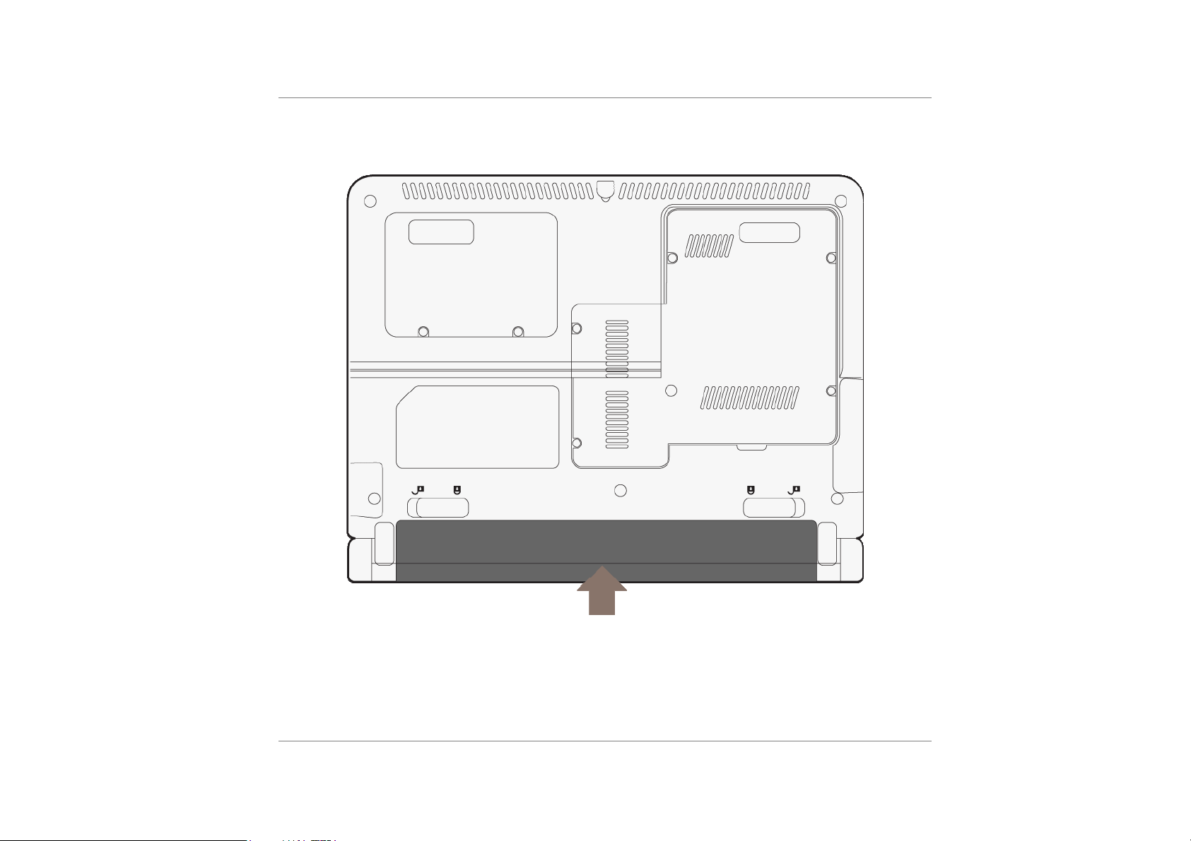
Preparing your computer.
Install the Battery Pack
Connecting to a Power Source
You can use the provided AC adapter to supply your computer with power from an AC wall
outlet.
Place the computer so that you have easy access to its lift side.
3
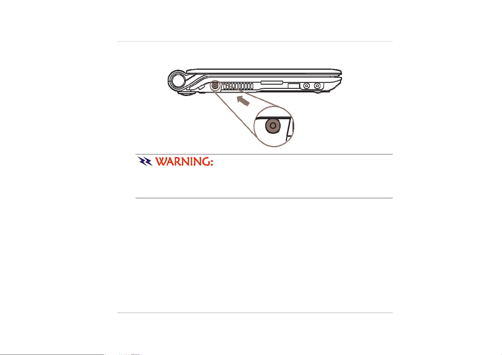
Plug the AC adapter’s connector into the DC-IN connector on the lift side of the computer.
Connect the power cord to the AC adapter and then to a wall outlet.
Do not use inferior extension cords as this may result in
damage to your Netbook. An AC adapter is provided along with y our Netebook. Do not
use a different adapter to power the computer, and do not use the AC adapter to power
other electrical devices. Try not to turn off or reset your Netbook while the hard disk is in
use.
4
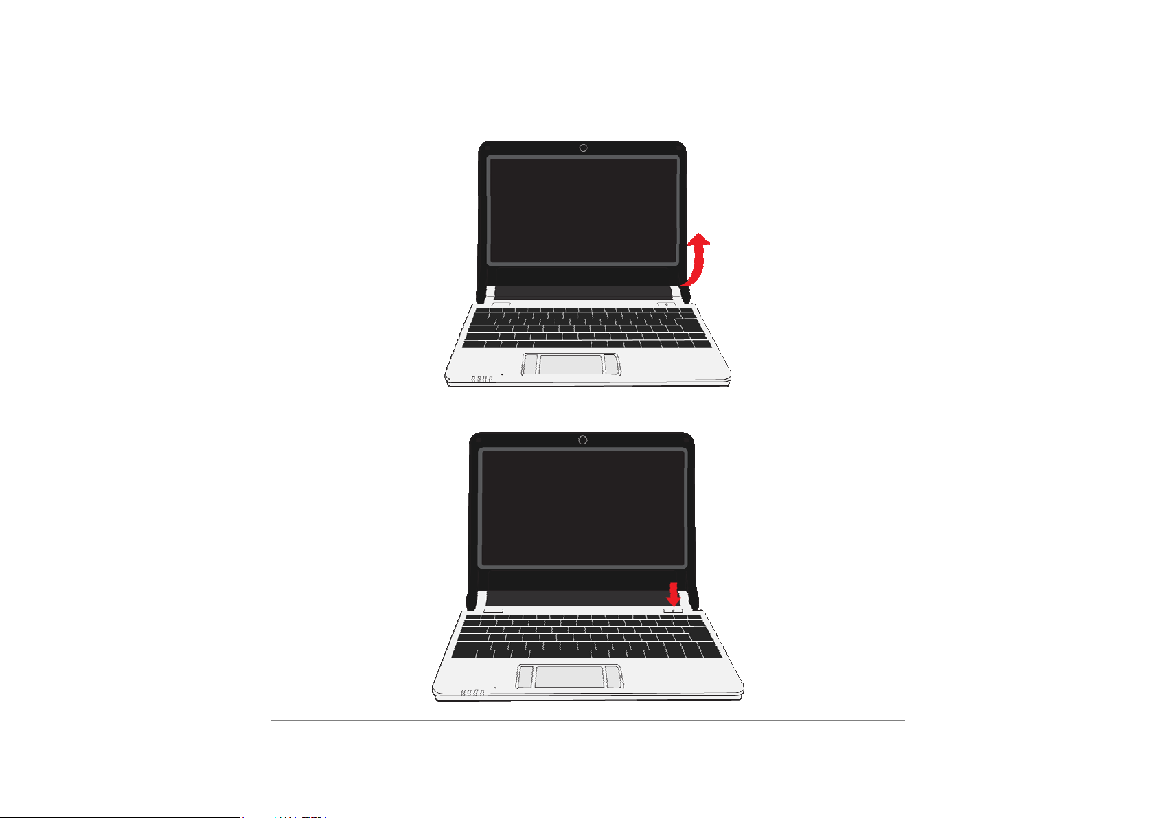
Open the Display Panel
Turning on Your Netbook Computer
5

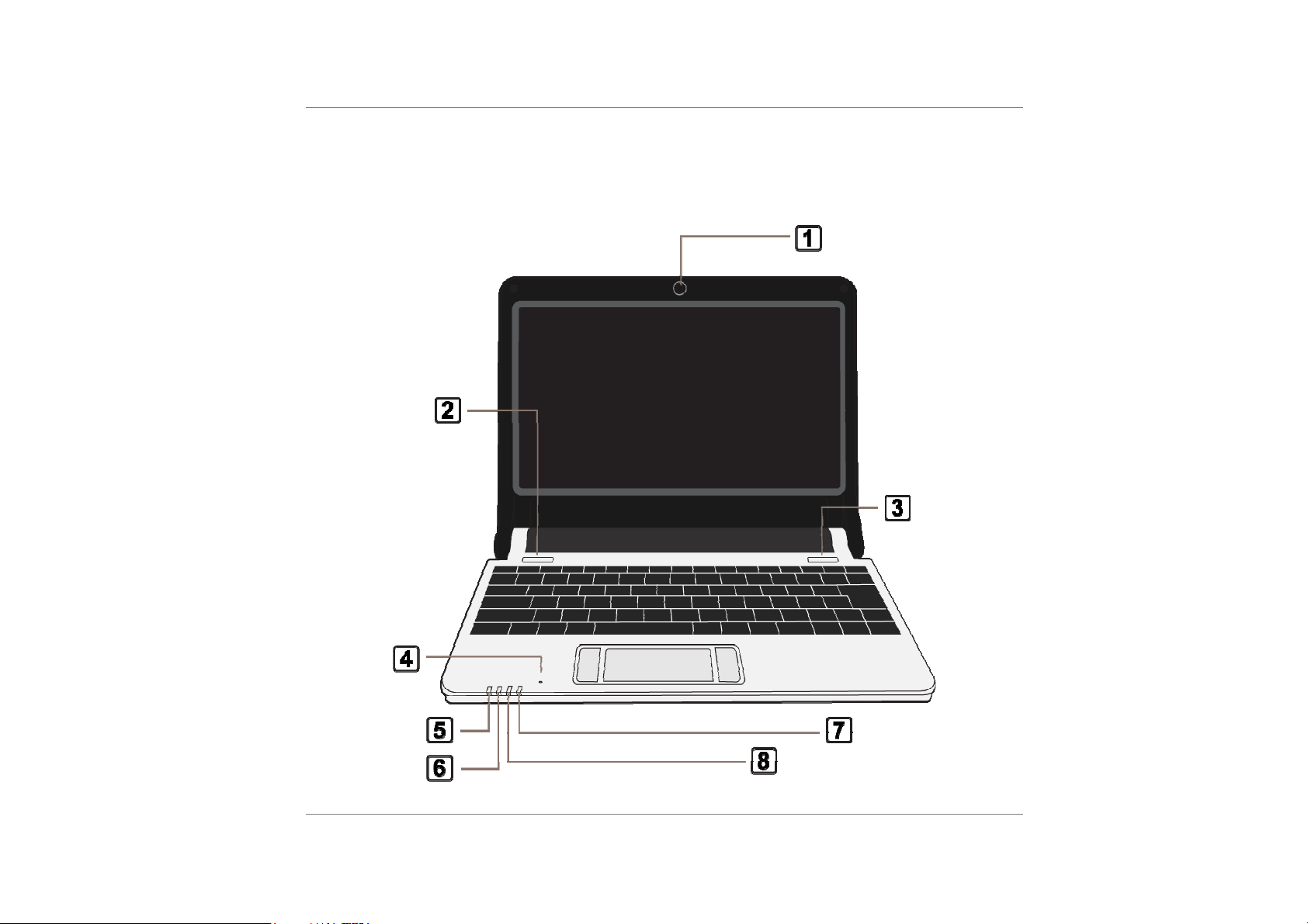
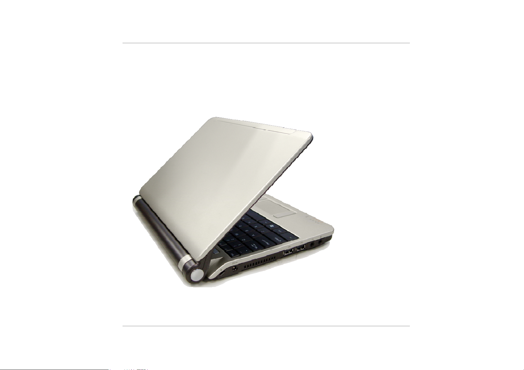
Learning the Parts
Open View
1

1. Webcam
The built-in webcam allows picture taking, video recording or video conferencing.
You can use the hotkey combination of Fn + F5 to open the web
camera.
2. LCD Display
Your Netbook computer is equipped with a replaceable color Liquid Crystal
Display (LCD) screen that supports up to 1024*600. It functions the same as a
desktop monitor. Use a soft cloth without chemical liquids (use plain water if
necessary) to clean the display panel.
3. Power Switch
The power switch turns the Netbook on and off. Press momentarily to turn on the
system. Press and hold for at least 3~4 seconds to turn off the system. The power
switch only works when the display panel is opened.
4. Keyboard
The keyboard is used to enter data. It has an embedded numeric keypad and
cursor control keys.
2
5. Digital Microphone
Use this microphone when you are on video conferencing.
6. LED Status Indicator
The LED Status Indicator displays the operating status of your Netbook. When a
certain function is enabled, an LED will light up. The following section describes its
indication.
7. TouchPad
The dual-button TouchPad is located below the keyboard. The TouchPad is
hardware-compatible with the IBM PS/2 mouse and software-compatible with the
Microsoft mouse.
8. TouchPad Buttons
The buttons below the TouchPad correspond to the left and right buttons on a
standard mouse.
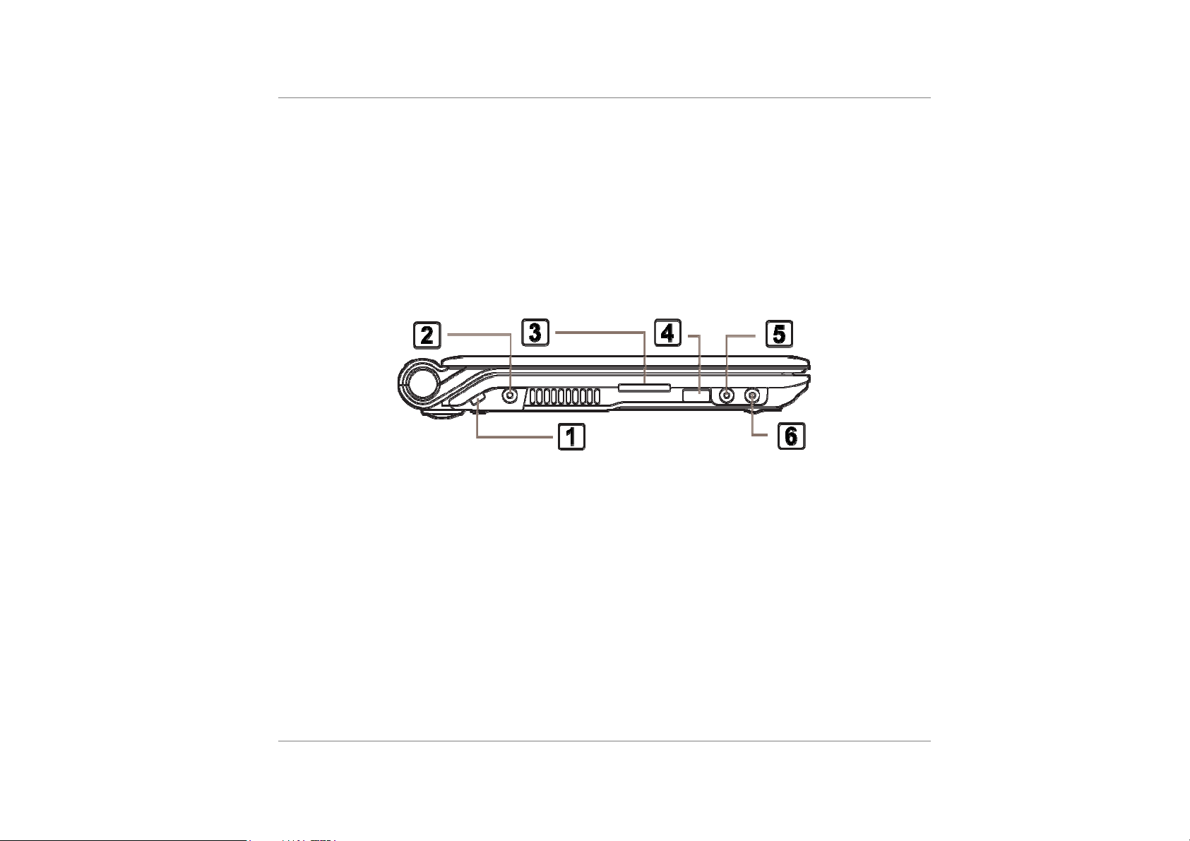
Left View
1. Kensington Lock Keyhole
Your computer includes a keyhole to be used with a standard Kensington lock.
You can connect the Netbook lock to a large object with the Kensington lock
to prevent theft of your Netbook.
2. DC IN Connector
Plug the AC adapter into this connector.
3. Card Reader
The slot is where PC Card is inserted. The system also supports MMC, SD, 2-1
card reader.
4. USB 2.0 Port
3
The Universal Serial Bus (USB2.0-compliant) port allows you to connect a wide
variety of devices to your computer at a rate of up to 480 Mbps. This port conforms
to the latest USB2.0 plug-and-play standards.
5. Microphone Jack
The microphone jack (3.5-mm diameter) is where you connect a microphone.
6. Stereo Headphone
The stereo headphone jack (3.5-mm diameter) is where you connect the
headphones or external speakers.
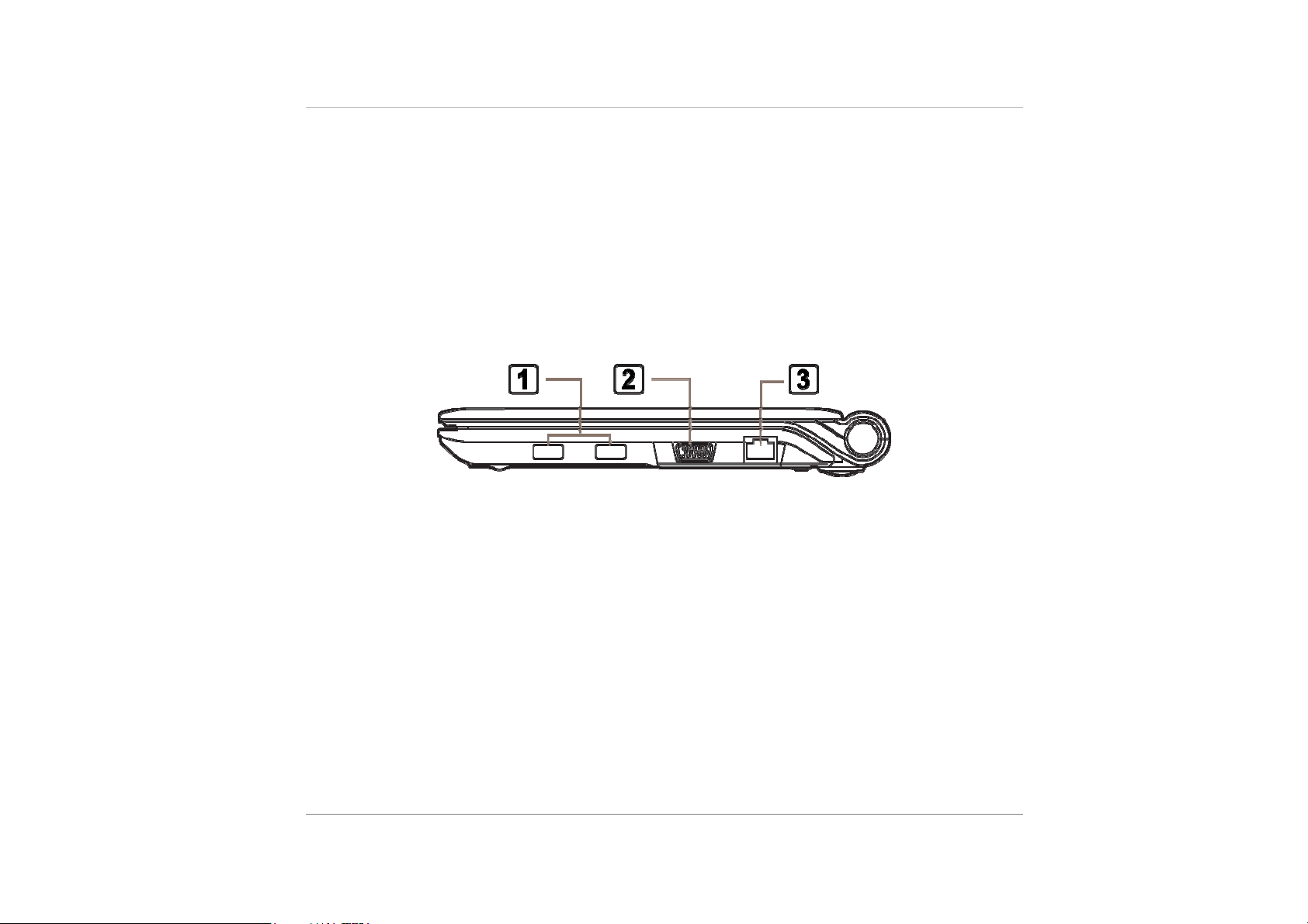
Right View
1. USB 2.0 Port x 2
The Universal Serial Bus (USB2.0-compliant) port allows you to connect a
wide variety of devices to your computer at a rate of up to 480 Mbps. This
port conforms to the latest USB2.0 plug-and-play standards.
4
2. CRT Port
The 15-pin VGA analog port is for connecting the external CRT monitor or
projector.
3. Ethernet / LAN Port
The port connects to a network hub via the RJ-45 cable and also conforms to
10/100/1000Base-TX transmission protocol.
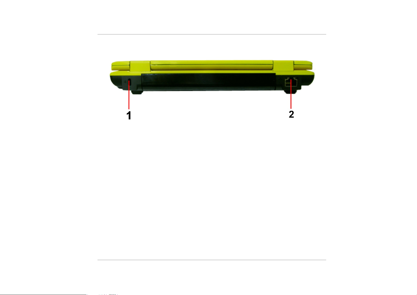
Rear View
5

Bottom View
6
1. Battery Release Latch
Slide the battery latch to release the battery pack
2. Battery Pack
The battery pack is a built-in power source for the Netbook.

System Status Indicator
7

LED Graphic Symbol Indication
The solid-state disk drive indicator blinks when data is
written to or read from the disk drive.
The battery charge indicator (LED) shows the status of
the battery’s power as follows:
Green: This indicate the system is power ON.
Orange: This indicate the battery is charging when the
system is power off.
Off: This indicate the system is power off an d the syste m
stop charging.
When the built-in wireless LAN is enabled, this indicator
lights. This is only applicable on models with built-in
wireless LAN.
Flight mode to shuts down all RF function.
Number Lock is activated while light on .
Caps Lock is activated while light on.
8

Hot Keys Combination
The hot keys are imprinted in light blue color. Pres s the Fn ( function) key with the
corresponding function keys from Fn + Esc/F2/F3/F5/F10/F11/F12/End/←/→ to exec ute
different application for various operation.
+
Suspend mode – Press the Fn + F2 combination keys to enter the suspend mode.
+
WLAN mode – Press the Fn + F4 combination keys to Enable/Disable the wireless mode.
+
Bluetooth mode – Press the Fn + F3 combination keys Enable/Disable the Bluetooth mode.
+
Camera mode – Press the Fn + F5 combination keys to Enable/Disable the camera.
+
LCD/CRT mode – Press the Fn + F10 combination keys in switching to LCD/CRT mode.
9

+
Brightness Down – Press the Fn + F11 key to decrease the brightness of your screen
display
+
Brightness Up – Press the Fn + F12 key to increase the brightness of your screen display
+
Mute mode – Press the Fn + End key to mute the volume of any audio or video files the
system is playing.
+
Volume Down – Press the Fn + ← key to decrease the volume of any audio or video files
the system is playing.
10
+
Volume Up – Press the Fn + → key to increase the volume of any audio or video files the
system is playing.

r
Chapter 2
Starting You
Netbook
11

Operating on Ba ttery Power
Your computer comes with a rechargeable battery pack that lets you operate the computer
without an external power source.
We recommend you to use batteries that are approved by an
12

authorized dealer. Try not to use the wrong battery for it would cause serious damage to
your computer.
Battery Low-Power Warning
Low Battery Warning
Low battery condition occurs when battery power is reduced to 10%.
Very Low Battery Warning
Very Low battery condition occurs at 3 % power remaining. When the Netbook warns you of
its low battery condition, you will have about 3-5 minutes to save your current work.
Do not expose battery packs to temperatures below 0
degree Celsius (32 degreeF) or above 60 degree C (140F). This may adversely affect the
battery pack.
Charging the Battery and Charging Time
To charge the battery, while the battery pack is in the Netbook, plug the AC adapter into the
Netbook and an electrical outlet.
The charging time is approximately 2.5 hours when the Netbook is turned off and
approximately 3 to 4 hours where it depends what kind of progra m your sys tem is running.
When the battery is fully charged, the battery charge indicator becomes green.
Read Section Protecting Your Netbook in the beginning of this
manual for tips about how to maintain the battery pack. To achieve optimal battery
performance, you may need to do a battery calibration at a 3-month interval. To do this:
Fully charge the battery.
Fully discharge the battery in idle mode till it shutdown.
13

Fully charge the battery again.
Using Windows Power Options
Windows Power Management provides basic power saving features. In the Windows Power
Options Properties [Start > Settings > Control Panel > Power Options] dialogue box, you
may enter time-out values for display and hard disk drive. Windows power manager saves
power by turning off hard drive after 1 minute of inactivity, for example.
Windows’ Power Options
The power management control panel in Windows XP Home, known as Power Schemes, is
designed to provide the user with an easy-to-use interface. The Power Schemes tab can be
found in the Power Options Properties panel that is accessible via the contr ol panel window.
Schemes are easy to understand, based on Netbook usage scenarios, and control not only
processor power usage but other system peripherals as well.
14

Suspend Mode
Standby Suspend
The system automatically enters this mode after a period of inactivity, which is set in the
Power Schemes dialog box. In Standby mode, hardware devices, such as display panel and
hard disk, are turned off to conserve energy.
15

Hibernate Suspend
In this mode, all system data are saved in the hard disk befor e powering down. When this
mode is activated, all system state and contents are saved to the hard disk drive after a
period of inactivity defined by the user.
Touchpad
Your Netbook touchpad is compatible with the PS/2 mouse. A device driver is not required
for working with application software that supports PS/2 mouse operation. The Touchpad is
a pressure sensitive pointing device that provides all the features of a two-button mouse. Its
primary function is to move the cursor around the screen.
16
Left button – click once to select an item, double-click to open a file or program.
Right button – use the right button to open special menus.

Graphic Subsystem
Your computer uses a high performance 10.1 inch LCD panel with high resolution and multimillion colors for comfortable viewing.
Audio Subsystem
Your computer’s audio subsystem is Sound Blaster Pro-compatible.
Voice Recording
A built-in microphone allows you to record sound. You will need to use audio processing
software to enable the built-in microphone. For example, you may use Microsoft Sound
Recorder.
Ethernet
Your computer is equipped with a 10/100MBase-TX Fast Ethernet network adapter. Connect
the active LAN cable to the RJ-45 LAN port located on the le ft side of the computer. This
allows you to access and transmit data in the local area network.
Connecting to the Network
Use Unshielded Twisted Pair (UTP) Ethernet cable only.
Insert one end of the UTP cable into the network connector until the connector snaps
securely into the receptacle.
Either connect the other end of the cable to an RJ-45 jack wall outlet or to an RJ-45 port on
a UTP concentrator or hub in the network.
17

r
Chapter 3
Customizing You
Computer
18

C
C
C
Using System Setup
System Setup is used when changing the booting priority, system password or adding new
devices.
After turning on your computer, when the booting screen appears, press <F2> to enter the
initial System Setup screen.
U
U
U
S
S
S
T
T
T
O
O
O
M
M
M
I
Z
I
I
Z
I
I
N
N
G
G
O
Y
O
Y
U
U
R
R
C
C
O
O
M
M
P
P
U
U
T
T
E
E
R
R
R
E
T
U
P
M
O
C
R
U
O
Y
G
N
I
Z
19

System Setup Menus
Main Menu
Configures the basic system environment
Advanced Menu
Configures OS and major chipset options of the system.
Security Menu
Configures system security options.
Boot Menu
Configures booting options.
Exit Menu
Exits System Setup
System Setup Navigation Keys
20
«/- - Use to select Boot Device
Ã Ä - Moves between menus
ÅÆ - Moves up and down between fields
Enter – Selecting the sub menu
F9 - Restores default values

F10 - Saves changes and exits System Setup
Exit - Exits the current sub menu or opens the Exit menu.
Configures the Password
Setting the Supervisor Password
This serve as a restriction of your system access to authorized
users only.
1. Select the “Security” menu in the BIOS setup
2. On the “Set Supervisor Password” item, press <Enter>.
3. Enter a password, press <Enter>, re-enter the password for confirmation, and press <Enter> again.
4. When a message confirming the password configuration appears, press <Enter>.
21

Setting User Password
A password can also be set for other users to use the system.
Before you configure a user password, the supervisor password
must have been configured.
Other users can use the system with their user password but not access to the System
Setup.
It is only that the supervisor password is deactivate will also deactivates the user
password.
On the “Set User Password” item, press <Enter>, and complete step 3 and 4 mentioned in
“Configuring the Supervisor Password”.
Adjusting the Display
Click on your mouse right button to display this mini window on your screen.
Click on the “Properties” item.
22

Click on the “Settings”.
23

Click on the “Advanced” to enter the “Intel® Graphics Media Accelerator Driver for Mobile”
window display.
24
Click on the “Graphic Properties”.

Display Devices
Select the “Display Devices” to indicate the display connected to your system.
25

Display Settings
Adjust the color quality, screen resolution and refresh rate of your display.
26

Color Correction
Adjust the color rate of your display.
27

Hot Keys
These are all the available hot keys as your default setting in executing some of the major
functions. You can either add or change the available hot keys.
28

g
Chapter 4
Troubleshootin
29

T
R
O
U
B
T
R
O
T
R
Your computer has been fully tested and complies with the system specifications before
shipping. However, incorrect operations and/or mishandling may cause problems.
This chapter provides a reference for identifying and correcting common hardware and
software problems that you may encounter.
When you encounter a problem, you should first try to go through the recommendations in
this chapter. Instead of returning the computer and waiting for repair , you may easily solve
the problems by considering the following scenarios and possible solutions. If the error
continues, contact your reseller for service information.
Before taking further actions, consider the following suggestion s:
Check to see if the problem persists when all the external devices are removed.
Check to see that the green light indicator on the AC adapter is lit.
Check to see the power cord is properly plugged to the wall outlet and to the computer.
Check to see the power indicator of the computer is on.
Check to see if your keyboard is operational by pressing and holding any key.
Check for any incorrect or loose cable connections. Make sure the latches on the connectors
latch securely on to the receptor end.
O
U
U
B
B
L
L
L
E
E
E
S
S
S
H
H
H
O
O
O
O
O
O
T
T
T
I
I
I
N
N
N
G
G
G
30
Be sure you have not performed an incorrect setting on the hardware devices in the BIOS
Setup utility. A faulty setting may cause the system to misbehave. If you are not sure of the
changes you made, try to restore all the settings to factory defaults.
Be sure all the device drivers are installed properly. For example, without the audio driver
properly installed, the speakers and microphone will not work.
If external devices such as USB camera, scanner, printer do not function correctly when
connected to the system, it is usually the device’s own problem. Consult the device’s
manufacturer first.

Some software programs, which have not gone through rigorous coding and testing, may
cause problems during your routine use. Consult the software vendor for problem solving.
Legacy peripheral are not plug-and-play capable. You need to restart the system with these
devices powered up and connected first.
Be sure to go to BIOS SETUP and load DEFAULT SETTING after BIOS re-flash.
Be sure the Quick Key Lockout Switch on the bottom of the computer is not engaged;
otherwise the quick keys will not work.
Audio Problems
No speaker output
Turn up the volume dial located at the right edge of the computer. See Chapter 1 for its
location.
Software volume control is turned down in Microsoft Sound System or is muted. Double-
click the speaker icon on the lower right corner of the taskbar to see if the speaker has been
muted or turned down all the way.
Most audio problems are software-related. If your computer worked before, chances are
software may have been set incorrectly.
Sound cannot be recorded
Double-click the speaker icon on the lower right corner of the taskbar to see if the
microphone has been muted.
Click Options and select Properties.
Select Recording and click the OK button.
After Click OK button, the recording volume control panel will appear.
Go to [Start > Settings > Control Panel] and double-click the Multimedia icon (or Sounds
and Audio Devices icon).
31

Hard Disk Problems
The hard disk drive does not work or is not recognizable
If you had just performed a hard disk upgrade, make sure the hard drive connector is not
loose and the hard disk drive is also correctly seated.
The new HDD may need to be partitioned and reformatted. O/S and drivers will need to be
re-installed as well.
Check the hard disk indicator LED. When you access a file, the LED lamp should light up
momentarily.
The new HDD may be defective or is not compatible.
If your computer has been subjected to static electricity or physical shock, you may have
damaged the disk drive.
The hard drive is making abnormal whining noises
You should back up your files as soon as possible.
Make sure the source of noise is indeed from the hard drive and not the fan or other devices.
The hard disk drive has reached its capacity
32
Run Disk Cleanup utility in Windows. [Start > All Programs > Accessories > System Tools
> Disk Cleanup] The system will prompt you for what to do.
Archive files or programs that you had no longer used by moving them to an alternative
storage medium (floppy disk, optical record-able disk, etc.) or uninstall programs that no
longer use.
Many browsers store files in the hard drive as a cache to speed up the performance. Check
the program’s Online Help for instructions on decreasing the cache size or on removing
temporary Internet files.
Empty the Recycle Bin to create more disk space. When you delete files, Windows saves
them to the Recycle Bin.

The hard disk takes longer to read a file-
If you have been using the drive for a period, the files may be fragmented. Go to [Start >
Programs > Accessories > System Tools > Disk Defragmenter] to perform a disk
defragmentation. This operation may take a while.
Interrupt requests or problems with other hardware devices may have occupied the CPU
and therefore slows down the system performance.
The files are corrupted -
Run the Error-checking utility in Windows to check the HDD. Double-click My Computer.
Right-click C: and select Properties. Click Check Now in Error-checking in Tools.
Keyboard, Mouse and Touchpad Problems
The built-in touch pad performs erratically
Make sure there is no excess perspiration or humidity on your hand when using the touch
pad. Keep the surface of the touch pad clean and dry.
Do not rest your palm or wrist on the surface of the touch pad while typing or using the
touch pad.
Make sure Touch Pad On/Off function is not activated.
The characters on the screen repeat while I type.
You may be holding the keys down too long while you’re typing.
Keep the keyboard clean. Dust and dirt under the keys could cause them to stick.
Configure the keyboard to wait longer before the auto repeat feature starts. To adjust this
feature, Go to [Start > Settings > Control Panel], and double-click the Keyboard icon. A
dialogue box shows up with the adjustable settings for the keyboard.
33

Memory Problems
The POST does not show an increased memory capacity when you have
already installed additional memory
Certain brands of memory module may not be compatible with your system. You should
ask your vendor for a list of compatible DIMM.
The memory module may be defective.
Network Adapter/Ethernet Problems
The Ethernet adapter does not work
Go to [Start > Settings > Control Panel > System > Hardware > Device Manager]. Double-
click on Network Adapters and check if Intel Gigabit PCI Fast Ethernet Adapter appears as
one of the adapters. If it does not exist, Windows has not detected the Intel Gigabit Fast
Ethernet adapter or the device driver has not been installed properly. If there is a yellow
mark or red-cross on the network adapter, it may be a device or resource conflict. Replace
or update the device driver from the factory CD-ROM disk or consult Windows manual on
how to solve the resource conflict problem.
34
Make sure the physical connections on both ends of the cable are good.
The hub or concentrator may not be working properly. Check to see if other workstations
connected to the same hub or concentrator is working.
The Ethernet adapter does not appear to operate in the 100/1000Mbps
transmission mode
Make sure the hub you are using supports 10/100/1000 Mbps operation.
Make sure that your RJ-45 cable meets the 100/1000Base-TX requirements.
Make sure the Ethernet cable is connected to the hub socket that supports 100/1000Base-
TX mode. The hub may have both 100/1000Base-TX and 100/1000Base-T sockets.

A freeze on the system during program operation
An error occurs during program currently being used.
Solution: An error with the Windows OS. Reboot the system using the Power button.
System Not Resuming Operation
If the system will not resume operation after system operation has been suspended, check
the following possible causes:
Solution: The battery may either be defective, or discharge to a critically low level.
To correct this problem, connect an external power supply such as AC adapter.
The LCD screen is too dark or too bright
Solution: Adjust the LCD brightness. Press the hot key or Mobility Center to click on
the Brightness Up or Brightness Down.
The system can not shutdown properly
Solution: Press and hold the power button for 4~6 seconds until the system
shutdown manually.
What are the major steps to follow when the system does not turn on
properly after it shutdown
The system will turn after connecting the AC adapter; this indicates the battery is in low
status.
Solution:
Check if the LCD screen is accidentally switch to CRT display.
Remove the battery and reconnect the AC adapter to turn on and press on the Reset the
button to turn on the system.
35

Wireless LAN connection is disconnected after 2~3
minutes, and the connection is not recovered.
Solution: The reason may be caused by channel interference, change the channel
of the AP and reconnect.
The computer is unable to connect to the Internet.
Solution: Account for Internet service provider (ISP) is not properly configured. Ask
for your ISP assistance.
The Wireless LAN is connected, but I can not connect to or to another
computer.
Solution: Check the device driver is properly installed.
Check that the device driver is properly installed. If the driver is not properly installed, you
will find a yellow exclamation mark on the network icon by licking Start > Control Panel >
System > Device Manager > Network Adapters.
If there is a yellow exclamation mark, please reinstall the device driver with the system
software Media.
The signal strength is excellent but cannot connect to the network.
Solution: Check the TCP/IP properties are configured properly. When you connect
to an AP, click the Wireless Network Connection icon on the taskbar and select the
Support tab.
Contacting Your Dealer
If you still have a problem after reading the preceding section, the next step is to contact
your dealer.
Your dealer can determine if the problem is something that requires the computer to be
taken to the shop. Before you call your dealer, however, please have the following
information available:
Solution:
How is your computer configured? Your dealer needs to know what peripheral devices you
36

are using.
What messages, if any, are on the screen?
What software were you running at the time?
What have you done already to try to solve the problem? If you have overlooked a step,
your dealer may be able to solve the problem over the phone.
The system could not resume after it enter the Standby mode
Solution:
Standby Mode – allows the computer or program save into the RAM. The system will enter
the saving mode. Press any key to resume the system
Hibernate Mode – allows the computer or program save into the HDD. At this time the
power is completely turn off. Press any key to resume the system
The system can’t resume operation
Solution:
Malfunction of external memory or internal memory – an error will occur during saving
into the system memory, it will not execute normal operation
External peripheral connected to the system not compatible – such as external USB devices,
compact flash, MMC, Smart Media are complicated devices will easily cause the computer
to enter standby mode thus unable to resume operation
Operating System loses effect – the power saving mode of Microsoft operating system
adopt ACPI mode (advanced Configuration and Power Interface), the power scheme will be
handle by the OS thus affecting the power saving mode of the system
Battery problem
Charge the battery immediately as it enter the battery low status; system
can’t re-charge
Solution: To protect the battery, it is not recommended to charge the battery under
high temperature. The system battery will automatically charge when the battery
37

temperature reach the room temperature.
After charging, the indicator will display 95~99% still uncharged
Solution: The battery has the tendency to fully automatically discharged, once the
battery is charged it will lower its capacity.
When the system will automatically charged upon it reaches 94% capacity, this is a
normal condition in protecting the battery.
38

A
n
Appendix
Specificatio
39

S
N
O
I
T
A
C
I
F
I
C
E
P
S
P
S
S
P
CPU
Intel® ATOM N270 (1.6G) 533 MHz FSB, 512kB L2 Cache
HIPSETS
C
Core Logic: 945GSE + ICH-7M
M
EMORY
1GB DDRII SODIMM (Max 2GB)
VGA
GMA950 ultra low power Integrated 3D graphics
BIOS
INCLUDES SYSTEM & VIDEO
Boot from USB
Plug & Play
APM 1.2
E
E
C
C
I
F
I
I
C
A
T
I
O
O
I
T
A
C
I
F
N
N
S
S
40
ACPI 3.0
ATTERY BAY
B
Re-chargeable 32W Battery Pack (2S2P)
ASS AND STORAGE
M
SATA HDD 2.5”
Card Reader - SD/MMC Card slot
DISPLAY
LCD
10.1" WSVGA TFT LCD,
WEBCAM
LED backlight 1024X600 pixels

1.3M pixels, fixed lens
UDIO
A
Built in Stereo Speaker * 2
Built in Analog micro phone *1
Stereo Head Phone (3.5 mm)
OMMUNICATION
C
Wireless 802.11 b/g (Mini PCIe)
A
NTENNA
1 x Wireless LAN b/g
I/O
1 x Stereo Headphone (3.5 mm)
1 x Stereo Microphone (3.5 mm)
1 x RJ-45 connector
1 x CRT port
3 x USB 2.0 Port
1 x DC in Jack
BUTTON
Power Button
Functional short cut key
Touch pad with Left/Right Button
INDICATOR
LED
1 X HDD Active
1 X Battery Status
1 X Wireless activity
1 X Number Lock
41

1 X Caps Lock
AC/DC ADAPTER
Miniature Size Compact Adapter type (AC Plug on Power Brick)
AC 100~240Volt / DC 20V 2A 40W
ATTERY PACK
B
1 Removable Battery Pack
B
ATTERY CHARGE
Smart Charger
D
IMENSION
250X202X25.6 (mm)
W
EIGHT
1.2kg with battery
R
EGULATORY APPROVAL
EMC - CE/FCC/ BSMI/VCCI
Safety - UL/TUV/CB/CCC
42
RF - FCC ID,CE,TELEC,DGT,SRRC

Measured maximum SAR value is 0.00593 W/kg (body)
Statement:
This device complies with part 15 of the FCC Rules. Operation is subject to the following two conditions:
(1) This device may not cause harmful interference, and (2) this device must accept any interference received, including
received, including interference that may cause undesiredoperation.
Warning:
FEDERAL COMMUNICATIONS COMMISSION INTERFERENCE STATEMENT
This equipment has been tested and found to comply with the limits for a Class B digital
device, pursuant to part 15 of the FCC Rules. These limits are designed to provide reasonable
protection against harmful interference in a residential installation. This equipment generates,
uses and can radiate radio frequency energy and, if not installed and used in accordance with
the instructions, may cause harmful interference to radio communications. However, there is
no guarantee that interference will not occur in a particular installation. If this equipment does
cause harmful interference to radio or television reception, which can be determined by turning
the equipment off and on, the user is encouraged to try to correct the interference by one or
more of the following measures:
Reorient or relocate the receiving antenna
Increase the separation between the equipment and receiver
Connect the equipment into an outlet on a circuit different from that to which the receiver is connected
Consult the dealer or an experienced radio/TV technician for help
Caution:
Any changes or modifications not expressly approved by the grantee of this device could
void the user’s authority to operate the equipment.
RF exposure warning:
This equipment must be installed and operated in accordance with provided instructions and
must not be co-located or operating in conjunction with any other antenna or transmitter.
End-users and installers must be provide with antenna installation instructions and transmitter
operating conditions for satisfying RF exposure compliance.
This equipment must be installed and operated in accordance with provided instructions and
the antenna(s) used for this transmitter must be installed to provide a separation distance of
at least 20 conform all persons and must not be co-located or operating in conjunction with
any other antenna or transmitter. End-users and installers must be provide with antenna
installation instructions and transmitter operating conditions for satisfying RF exposure
compliance.
43
 Loading...