

AMT Datasouth Performax User Manual [en, es]

Performax
User's Manual
Part Number 103263
Rev. F

This device complies with part 15 of the FCC rules. Operation is subject to the following two
conditions:
1. This device may not cause harmful interference, and
2. This device must accept any interference received, including interference that may cause
undesired operation.
WARNING
CHANGES OR MODIFICATIONS TO THIS UNIT NOT EXPRESSLY APPROVED BY
THE PARTY RESPONSIBLE FOR COMPLIANCE COULD VOID THE USER'S
AUTHORITY TO OPERATE THE EQUIPMENT.
NOTE
This equipment has been tested and found to comply with the limits for a Class A digital
device, pursuant to Part 15 of the FCC Rules. These limits are designed to provide reasonable
protection against harmful interference when the equipment is operated in a commercial
environment. This equipment generates, uses, and can radiate radio frequency energy and, if
not installed and used in accordance with the instructions, way cause harmful interference to
radio communications. Operation of this equipment in a residential area is likely to cause
harmful interference, in which case the user will be required to correct the interference at his
own expense.
NOTE
When connecting the printer to a host computer system, always use shielded interface cables.
The use of non-shielded interface cables is a violation of the FCC emissions limits for a Class
A computing device. Do not leave unterminated interface cables connected to the printer.
This digital apparatus does not exceed the Class A limits for radio noise emissions from digital
apparatus set out in the Radio Interference Regulations of the Canadian Department of
Communications.
Le present appareil numerique n’emet pas de bruits radioelectriques depassant les limites
applicables aux appareils numeriques de la class A prescrites dans le Reglement sur le brouillage
radioelectrique edicte par le ministere des Communications du Canada.
i

Einhaltung mit betreffenden Bestimmungen kommt darauf an, dass geschirmte Ausfuhrungen
gebraucht werden. Fur die Beschaffung richtiger Ausfuhrungen ist der Betreiber verantwortlich.
DIESES GERAET WURDE SOWOHL EINZELN ALS AUCH IN KINER ANLAGE, DIE
ERNEN NORMALEN ANWENDUNGSFALL NACHBILDET, AUF DIE EINHALTUNG DER
FUNK-ENTSTOERBESTIMMUNGEN GEPRUEFT. ES IS JEDOCH MOEGLICH, DASS DIE
FUNK-ENTSTOERBESTIMMUNGEN UNTER UNGUENSTIGEN UMSTAENDEN BEI
ANDEREN GERAETEKOMBIKATIONEN NICHT EINGEHALTEN WERDEN. DER
BETREIBER IST FUER DIE EINHALTUNG DER FUNK-EUTSTOERUNGS
BESTIMMUNGEN SEIRER GESAMTEN ANLACE VERANTWORTLICH, IN DER DIESES
GERAET BETRIFBEN WIRD.
BESCHEINIGUNG DES HERSTELLERS/IMPORTEURS GS MARKED UNITS ONLY
Hiermit wird bescheinigt, dass der/die/das
Performax Model A600
(Gerat, Typ, Bezeichnung)
in Uebereinstimmung mit den Bestimmungen der
Vfg 1046/1984
(Amtsbkattverfugung)
funk--entstort ist.
Der Deutschen Bundespost wurde das Inverkehrbringen dieses Gerätes angezeigt und die
Berechtigung zur Ueberprufung der Serie auf Einhaltung der Bestimmungen eingeraumt.
Datasouth Computer Corporation
Name des Herstellers/Importeurs
WARNING
Any alteration or modification to this equipment may cause non-compliance to:
WARNUNG
Jegliche UmsteHung oder Abänderung dieses Gerätes kann Zuwiderhandlung gegen:
ADVERTENCIA
Cualquier alteracíon o modificacíon à este équipo podria causar el incumplimiento con:
ATTENTION
ii

Le changement ou la modification quelconque a cet equipement peut causer nonconformite avec:
UL Safety Standard 1950
IEC Safety Standard 950
CSA Safety Standard C22.2 No. 220
FCC Title 47, Part 15 regulations for Class A Computing Devices
VDE EMI regulations Vfg 1046, Class B (GS marked units only)
EN5022 Class A Limits
Canadian Radio Interference Regulations
CRC c.1374, Class A, Canada
zur Folge haben.
CAUTION
The printer must have the correct line fuse installed for the selected input voltage.
VORSICHT
Eine entsprechende Sicherung muß für die gewählte Voltzahl installiert werden.
PRECAUCION
El impresor tiene que tener instalado el fusible debido para el voltaje de entrada.
AVIS
L'imprimante doit avoir installè juste ligne de fusible pour le voltage d’entrée choisi.
WARNING
The operator must disconnect the printer from the A.C. power supply before performing any
corrective action procedure that requires reaching into the printer.
WARNUNG
Der Drucker muß von der Stromversorgung abgekuppelt werden, ehe irgend welche BerichtigungsMaßnahman durchgeführt werden, die es notwendig machen, in das Innere des Druckers zu langen.
ADVENTERCIA
El usuario tiene que desconectar el impresor de la corriente altena AC antes de hacer cualquier
procedimiento de corección que requiera meter la mano dentro del impresor.
iii
ATTENTION

Il faut que l'usager dêbranche l'imprimante de la source de puissance AC avant de réaliser
quelconque procédure rectificatif que oblige mettre la main dans l'imprimante.
WARNING
Changes or modifications to this unit not expressly approved by the party responsible for
compliance could void the user's authority to operate the equipment.
WARNUNG
Umstellung oder Abänderungen diese Gerätes durfen nur mit ausdrücklicher Einwilligung der für
die Zulassung verantwortlichen Partei geschehen und Verstöße dagegen könnten zur Folge haben,
daß die Betriebserlaubnis für diese Ausrustung widerrufen wird.
ADVERTENCIA
Los cambios o modificaciones a esta unidad no aprobados explicitamente por la parte responsable
del cumplimiento podrian invalidar la autoridad del usuario para hacer funcionar el equipo.
ATTENTION
Les changements et modifications faits à cet unité et pas explicitement approuvés par la partie
responsable de la conformité peuvent annuler l’autorité de l’usager à operer l’équipement.
WARNING
Connect 115v (230v) units to 115V (230V) outlets only!
WARNUNG
115V (230V) Geräte nur an 115V (230V) Steckdosen anschlieben!
ADVERTENCIA
Conectar unidades de 115V (230V) a tomas solamente de 115V (230V)!
ATTENTION
Brancher les unites 115V (230V) avec seulement les prises 115V (230V)!
WARNING
iv
The printhead gets hot during use. Wait until the printhead is cool before handling the printhead.

WARNUNG
Die Druckköpfe erhitzen sich, während das Gerät in Betrieb ist. Die Druckköpfe müssen erst
ausgekühlt sein, bevor sie angefaßt werden dürfen.
ADVERTENCIA
La cabeza impresora se calienta el uso. Esperar hasta que la cabeza impresora se enfrie antes de
manipularla.
ANTENTION
La tête d’impression se chauffe pendant l’usage. Attendre que la tête d’impression soit froide avant
de la toucher.
WARNING
Connecting this equipment to an underground power receptacle can result in the risk of electrical
shock.
WARNUNG
Der Anschluß dieses Gerät an einen ungeerdeten Kraftstrom-Behälter kann einen elektrischen
Schock verursachen.
ADVERTENCIA
El conectar este equipo a una toma de corriente no conectada a tierra puede resultar en el riesgo de
un corrientazo.
ATTENTION
Branchant cet équipement à une prise pas connecté à terre peut rèsulter en risque de choc
électrique.
WARNING
Make certain the printer is disconnected from the A.C. power supply before reaching into the
printer to perform any cleaning or maintenance task.
WARNUNG
v
Der Drucker muß vom Stromnetz abgekuppelt sein, ehe irgend welche Wartungs-oder
Reinigungsarbeiten vorgenommen werden können.

ADVERTENCIA
Asegurar que el impresor se desconecte de la corriente altena AC antes de meter la mano dentro del
impresor para cualquier labor de limpieza o mantenimiento.
ATTENTION
Assurer que l’imprimante n’est pas brancher à la source de puissance AC avant de mettre la main
dans l’imprimante pour nettoyage ou entretien.
SILICON SOFTWARE
1989 Ready Systems Corp. All rights reserved. Unpublished-rights reserved under the copyright
laws of the United States.
RESTRICTED RIGHTS LEGEND
Use, duplication or disclosure by the Government is subject to restrictions as set forth in
subparagraph (c)(1)(i) of the Rights in Technical Data & Computer Software clause at DFARS
252.227-7013.
READY SYSTEMS, 470 POTRERO AVENUE, SUNNYVALE, CA 94086
Table Of Contents
Title Page
Overview
vi

Printer Overview …………………………………........................................ 1
Quick Start Up Procedure …………………………….................................. 2
Chapter 1: Installation And Start Up
Unpacking The Printer ……………………………..................................... 1-1
Selecting A Site For The Printer …………………………............................. 1-2
Printer Parts …………………………………….............................................. 1-4
Shipping Material Removal …………………………................................ 1-6
Shipping Thumbscrews ……………………………. ................................. 1-6
Shipping Carriage Clip ……………………………….................................. 1-7
Installing The Power Cord …………………………… ................................ 1-8
Installing The Ribbon Cartridge …………………………............................. 1-9
Loading Forms …………………………………........................................... 1-13
Printer Self Test …………………………………............................................ 1-14
Interfacing ……………………………………............................................... 1-15
RS-232 And RS-422 Serial Interface Configuration ……………............... 1-15
Chapter 2: Forms Handling
Recommended Types, Sizes And Weights …………………..................... 2-1
Continuous Forms …………………………………..................................... 2-1
Single Part Cut Sheets ………………………………..................................... 2-1
Multi-part Cut Sheets ……..………………………….................................... 2-1
C-Size Drawing Paper ………………………..…….................................... 2-2
Paper Paths …………………………………................................................ 2-3
Forms ……………………………………................................................... 2-4
Bottom Feed Path …………………………………...................................... 2-4
Front Feed Path ………………………………….......................................... 2-8
Top-Of-Form Adjustment ………………………….................................... 2-10
Tear Off Adjustment .………………………………..................................... 2-11
Form Thickness Adjustment ………………………….................................. 2-12
Changing From Continuous Forms To Cut Sheets ………………….............. 2-14
Changing From Cut Sheets To Continuous Forms ………………................ 2-14
Paper Out When Using Continuous Forms …………………..................... 2-15
Paper Out When Using Cut Sheets ………………………........................... 2-15
Chapter 3: Keypad Operation
Arrangement Of Keys And Indicators …..……………………........................ 3-1
Description Of Indicators ……………………………….................................... 3-2
Primary Key Functions ………………………………....................................... 3-3
vii

LCD Display ……………………………………............................................... 3-6
Chapter 4: Features and Profiles
Features ………………………………………….................................................. 4-1
Profiles …………………………………………................................................... 4-1
Secondary Key Functions ……………………………….................................. 4-2
LCD Display ………………………………………............................................. 4-4
Profile Feature Listing …………………………………….................................... 4-4
Changing Features In A Profile ………………………………............................ 4-5
User Programmable Features ………………………………............................. 4-8
Group 1 Forms Control ………………………………….................................. 4-8
Group 2 Personality …………………………………….................................... 4-12
Group 3 Printer Control …………………………………................................. 4-14
Group 4 Serial Control ………………………………….................................. 4-17
Group 5 Parallel Control …………………………………................................ 4-19
Group 6 Profile Control …………………………………................................. 4-20
Group 7 Diagnostics ……………………………………................................... 4-21
Chapter 5: Troubleshooting And Maintenance
Scheduled Maintenance ………………………………................................... 5-1
Error Messages ……………………………………........................................... 5-3
Paper Out Condition …………………………………..................................... 5-3
Non-Volatile Memory Error ……………………………............................... 5-3
Paper Jam ……………………………………….............................................. 5-4
Carriage Jam ………………………………………........................................... 5-6
Parity Error ………………………………………............................................. 5-8
Ribbon Life End ……………………………………....................................... 5-10
Cover Open ………………………………………........................................... 5-10
Access Open ………………………………………........................................... 5-11
Keypad Lockout ……………………………………........................................ 5-11
Printer Diagnostics ……………………………………....................................... 5-11
Print Profile ………………………………………….................................... 5-11
Firmware Test ……………………………………….......................................... 5-12
PrintheadTest ………………………………………........................................ 5-13
Run Mode Test …………………………………….......................................... 5-14
Run Self-Test ………………………………………........................................... 5-15
Display Mode ……………………………………….......................................... 5-16
Troubleshooting ………………………………............................................ 5-16
Troubleshooting Table ……………………………..................................... 5-18
viii
Appendix A: Printer Specifications
Appendices

Printer Characteristics ………………………………..................................... A-1
Emulations …………………………………................................................ A-2
Font Specifications ………………………………........................................ A-3
Paper Feed Specifications …………………………….................................. A-3
Forms Mode Change ………………………………...................................... A-4
Communications Interface ……………………………................................. A-4
Operator Panel Functional Description ………………………....................... A-5
Ribbon Cartridge/Drive ……………………………...................................... A-5
Physical ……………………………………................................................... A-5
Electrical ……………………………………................................................. A-5
Environmental …………………………………........................................... A-5
Shock And Vibration ……………………………........................................ A-6
Compliances …………………………………............................................... A-6
Appendix B: Interface Specifications
Parallel Interface …………………………………........................................... B-1
Parallel Interface Enable/Disable …………………………............................. B-6
RS-2: 232C Serial Interface ……………………………................................... B-7
Serial Interface Enable/Disable ………………………….............................. B-9
Appendix C: Default Tables
Appendix D: System Administration Features
Features Available In The Hidden System Control Group …………......... D-2
Key Functions Which May Be Locked Or Delayed ……………................ D-5
Appendix E: Ribbon Life Monitor Feature
Ribbon Monitor Operation ……………………………................................. E-1
Check Ribbon ……………………………………........................................... E-1
Replace Ribbon ……………………………………........................................ E-2
Appendix F: ASCII Conversion Chart
Overview
Printer Overview
This dot matrix impact printer provides high-speed performance, a rugged, round-the-clock duty
cycle, and flexibility to handle a variety of printing applications.
ix

Feature Highlights:
A straight paper path
18 wire ballistic printhead
Demand document printing
Auto-tear off feature
Paper parking and reloading of fan fold forms at the touch of a key
Four individual, user-defined print profiles to speed printer setup when changing forms
Epson FX, DEC LA120, IBM Graphics printer, IBM Proprinter XL, DS-180, and DPCL
emulations
Optional Cut Sheet paper path
Ribbon Life Monitor feature that tracks usage rate of ribbon
Quick Start Up Procedure
The following is an abbreviated installation and start up procedure for users who are familiar with
printer products. If you are not experienced with printers, please refer to Chapter 1.
1. Place the printer on a printer stand.
1

2. Remove shipping thumb screws (see figure on page 1-6).
3 . Remove clip securing carriage belt (see figure on page 1-7).
4. Use the printhead adjustment lever on the top right hand side of the printer to move
printhead away from the platen.
5. Install ribbon cartridge.
6. Install power cord.
WARNING
CONNECT 115V UNITS TO 115V OUTLETS ONLY!!
7. Turn printer on.
8. Position left tractor. Align pins with first mark (see page 2-5). Position paper guides, one
next to each tractor and one in the middle of the form.
9. Place paper in tractors. For paper less than 8.5 inches wide see Forms Setup Procedure, page
2-5.
CAUTION
IMPROPER MARGIN SETTINGS CAN LEAD TO PRINTHEAD DAMAGE!!
DO NOT PRINT OVER TRACTOR HOLES OR OFF PAPER EDGE.
10. Press the Load key. Move forms adjustment lever all the way forward (to the rear of the
printer), then back two detents for single part paper. For multi-part forms see page 2-13.
11. Press the Setup key.
12. Press the Feature key once to select Self-Test.
13. Press the Enter key.
This will start the printer self test. The test may be stopped by pressing the On/Off Line key, or the
Enter key.
2

Chapter 1: Installation and Start Up
Unpacking the Printer
Remove all items from the shipping carton:
Dot Matrix Printer
Ribbon Cartridge
3

Power Cord
Accessory Kit: User's Manual
Programmer's Manual
Three-Ring Binder
Warranty card
If any items are missing, please contact your distributor. Save the shipping carton and all packing
materials. These items will be needed in the event the printer is to be shipped.
CAUTION
SHIPPING THE PRINTER IN ANY CONTAINER OTHER THAN
ITS ORIGINAL PACKAGING MAY RESULT IN SHIPPING
DAMAGE AND MAY VOID THE WARRANTY.
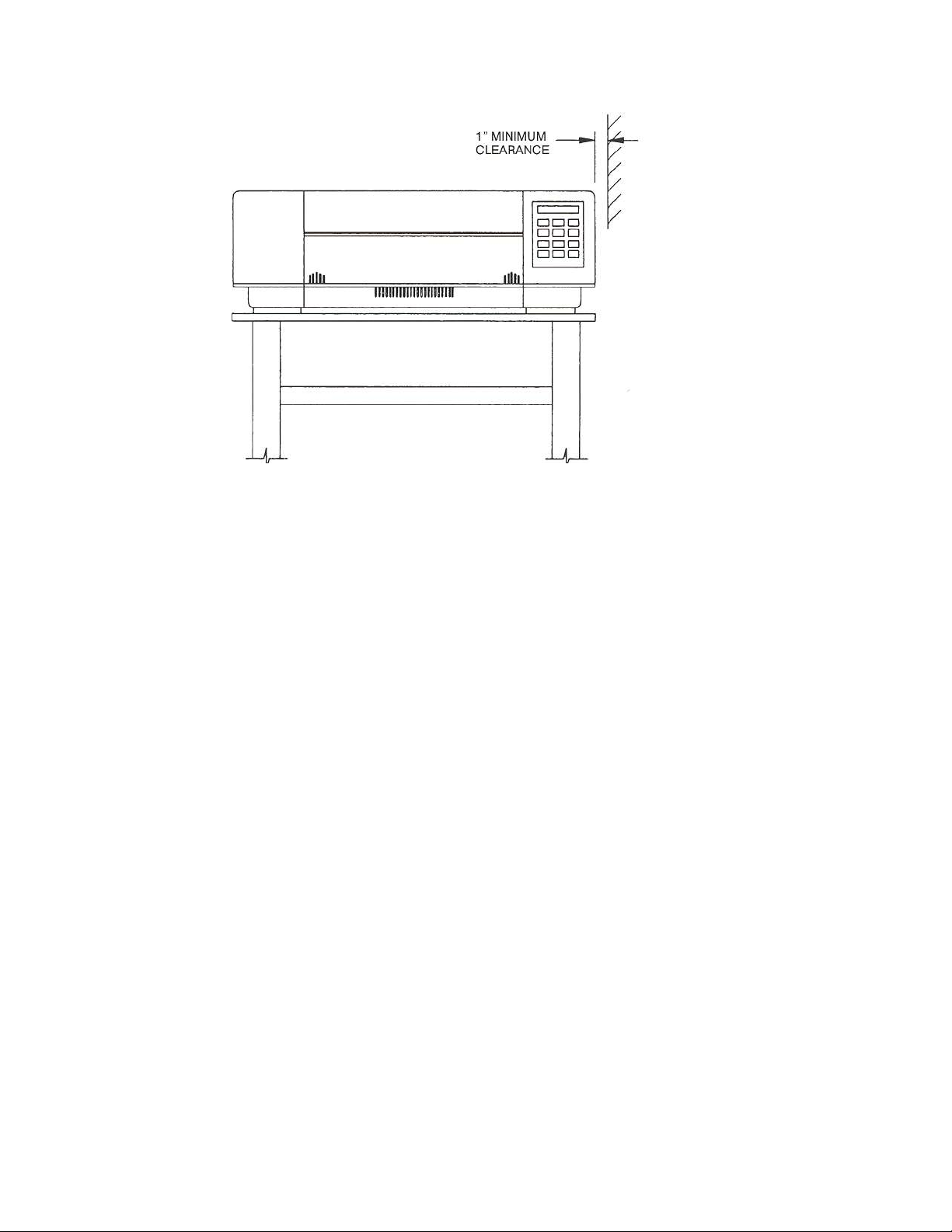
Selecting A Site For the Printer
1-1

The printer weighs approximately 47 pounds and must be located on a sturdy printer stand.
Sufficient ventilation must be provided. Leave a minimum of 4 inches of space at the back of the
printer and a minimum of 1 inch of space on either side.
1-2
Locate the printer near a grounded power receptacle. Do not use an extension cord to connect the
printer. Do not plug any other equipment into the same receptacle.
Avoid the following:
Direct sunlight or excessively illuminated areas
Direct placement in front of air conditioning or beating vents
Extreme high or low temperatures
Exposure to excessive dirt or dust
Exposure to vibration or mechanical shock
Excessive humidity or condensation
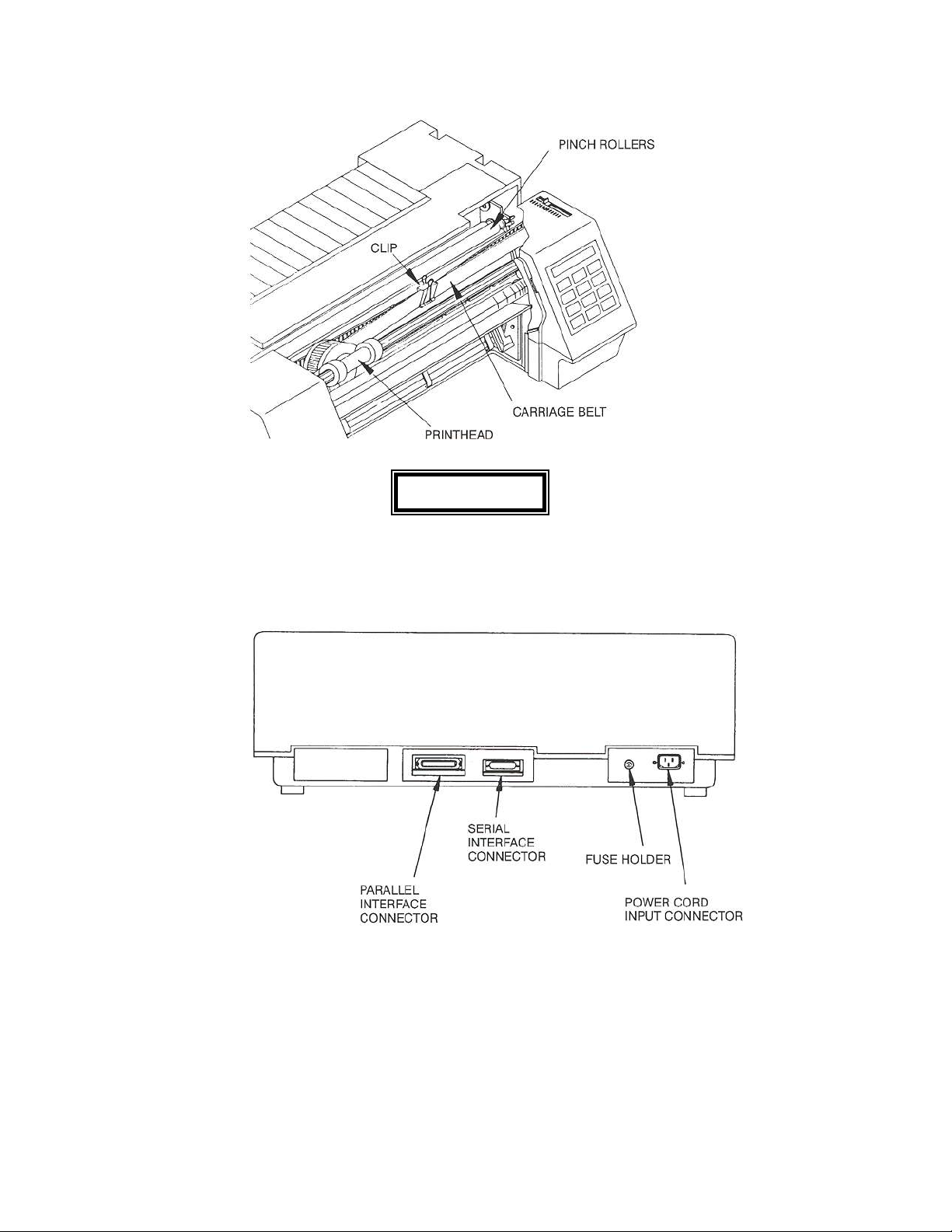
Printer Parts
1-3
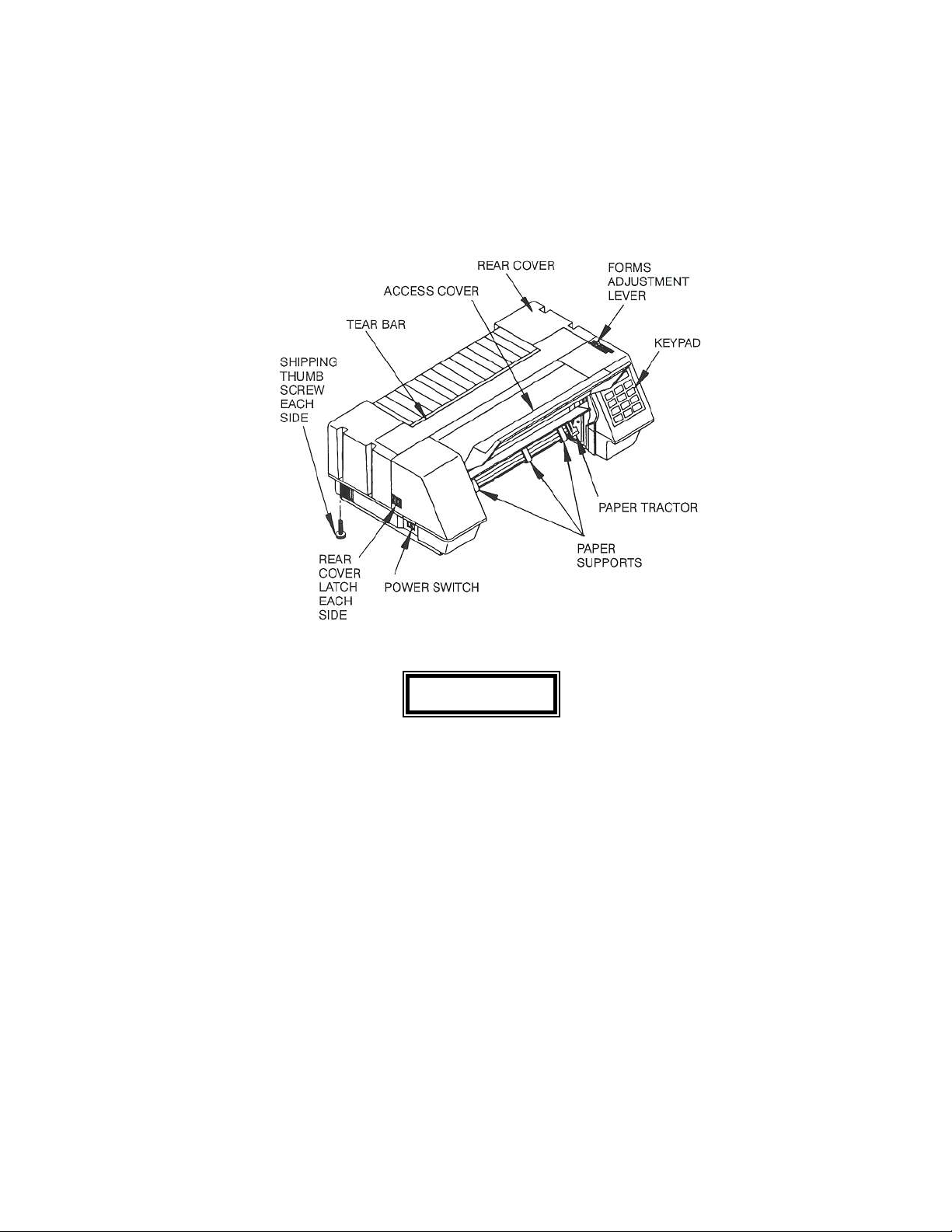
Use the following illustrations to locate all of the major printer parts.
CAUTION
REMOVE REAR COVER SHIPPING SCREWS (2)
BEFORE ATTEMPTING TO OPEN THE REAR COVER SET.
1-4
CAUTION
REMOVE CLIP SECURING CARRIAGE BELT BEFORE
ATTEMPTING TO OPERATE THE PRINTER.
Shipping Material Removal
1-5
The following must be removed from the printer prior to operation.
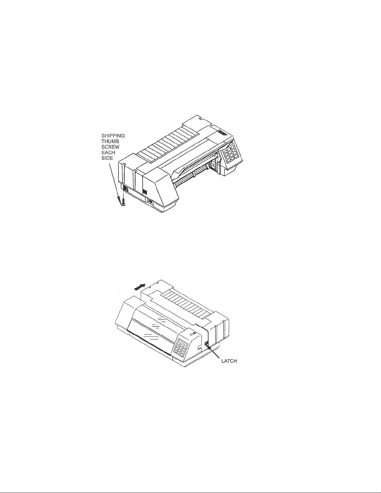
Shipping Thumbscrews
Remove the two thumbscrews located on either side and rear bottom of the printer.
Locate cover latches on each side of printer. Simultaneously press each latch and slide rear cover
toward the rear of printer.
Shipping Carriage Clip
1-6
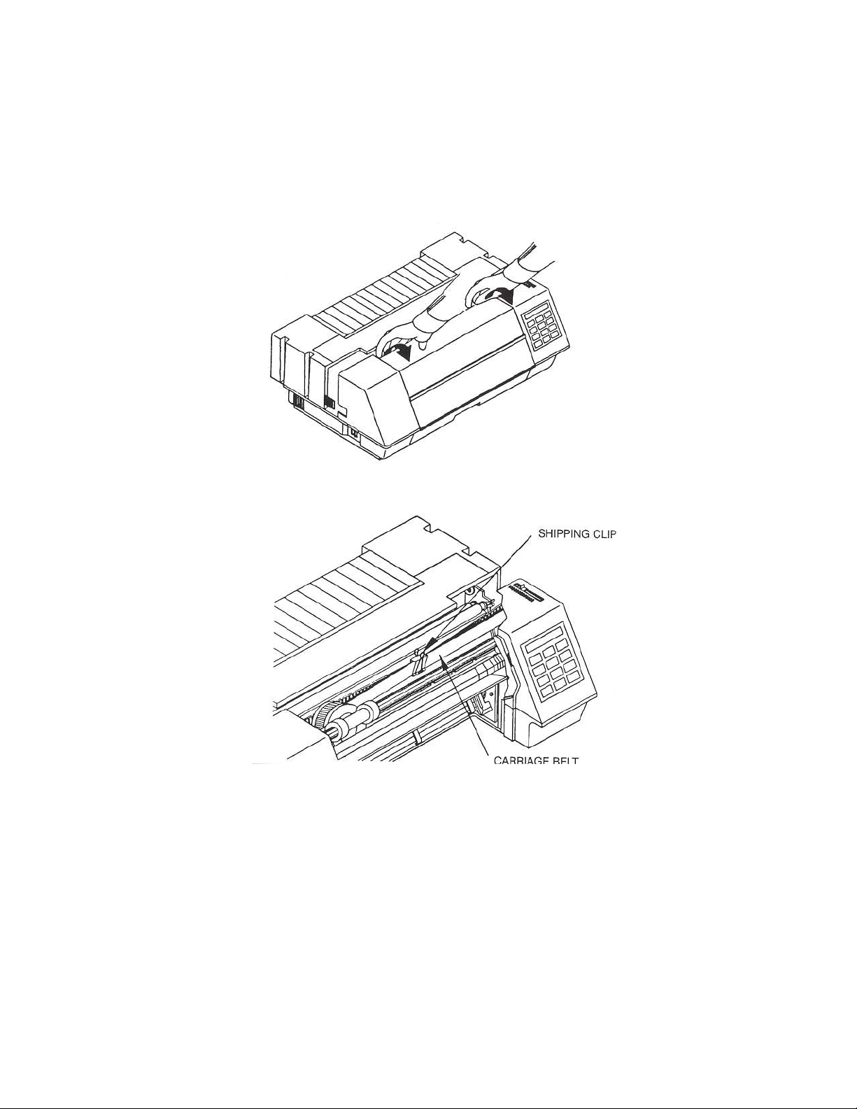
Make sure the bottom half of the access cover is fully closed. Pull on the top access cover and pivot
the cover toward the front of the printer to expose the printhead and carriage assembly.
Remove shipping clip from carriage belt.
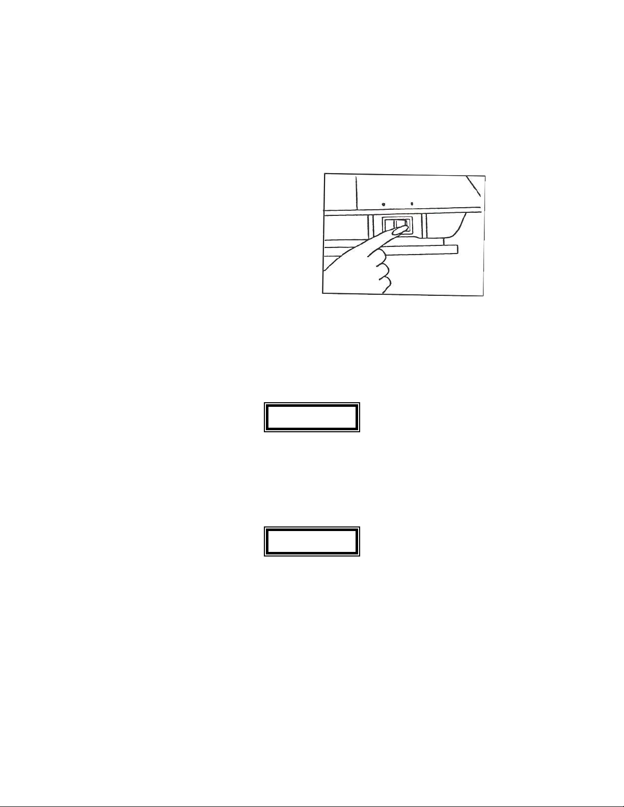
Installing the Power Cord
1-7
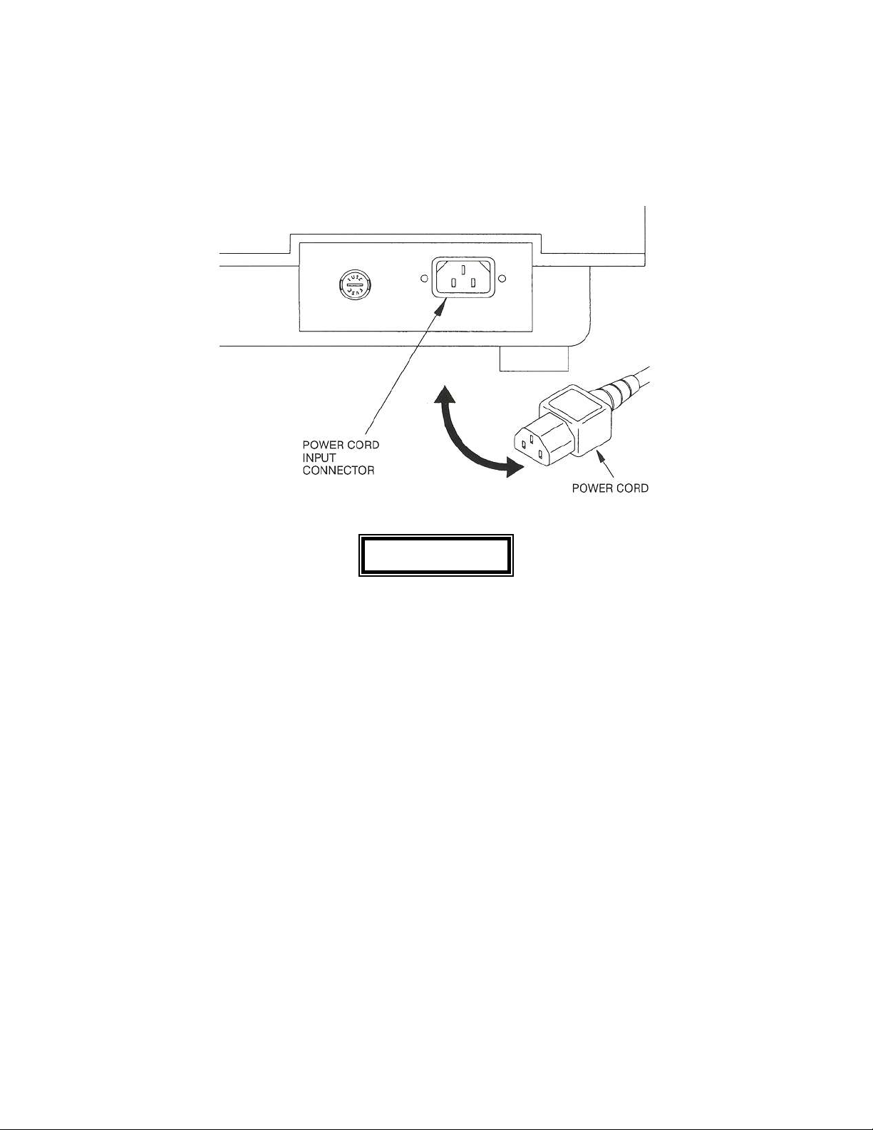
1. Set the power switch to OFF.
2. Install the power cord into the printer as shown.
WARNING
CONNECTING THIS EQUIPMENT TO AN UNGROUNDED POWER
RECEPTACLE CAN RESULT IN ELECTRICAL SHOCK.
3. Plug the other end of the power cord into a grounded AC outlet. The voltage of the AC
power receptacle must match the voltage rating on the power cord receptacle label. A
grounded outlet must be used. Plugging the printer into an outlet which is not grounded may
result in increased radio frequency noise generation and may also cause erratic printer
operation.
Installing the Ribbon Cartridge
1-8
To install a ribbon cartridge:
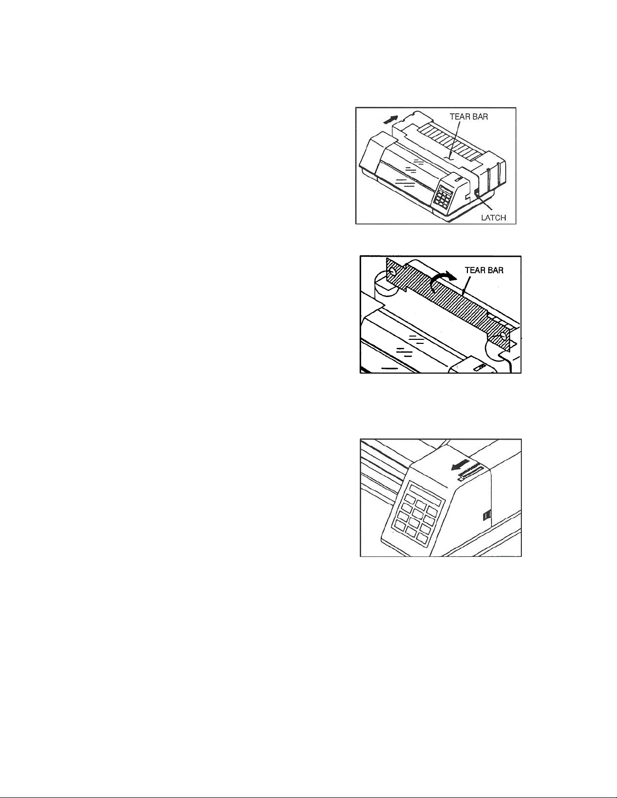
1. Take the printer off-line.
2. Press in on the latches at the sides
of the printer to release the rear
cover and slide the rear cover back.
3. Rotate the tear bar as shown and
rest it on top of the rear cover.
4. Slide the forms adjustment lever toward
front of printer as shown. This moves
the printhead away from the paper.
5. Move the pinch roller into the upper
1-9
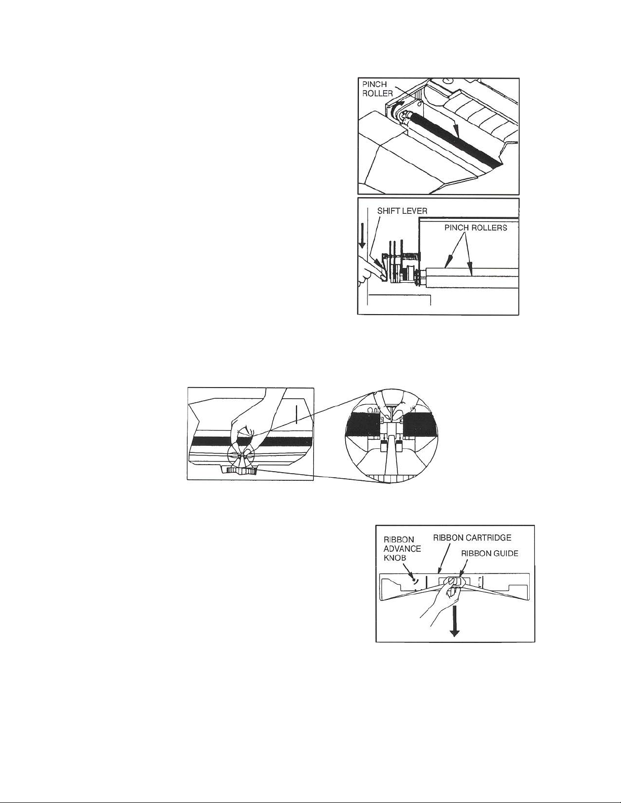
recess area.
6. For units with the cut sheet
option, move shift lever
toward front of the printer.
7. Remove the ribbon guide from printhead and remove existing ribbon cartridge from printer
(if installed).
8. Remove the ribbon guide from the new ribbon
cartridge.
9. Remove the two shipping tabs
BEFORE installation.
10. Install the ribbon onto the ribbon
1-10
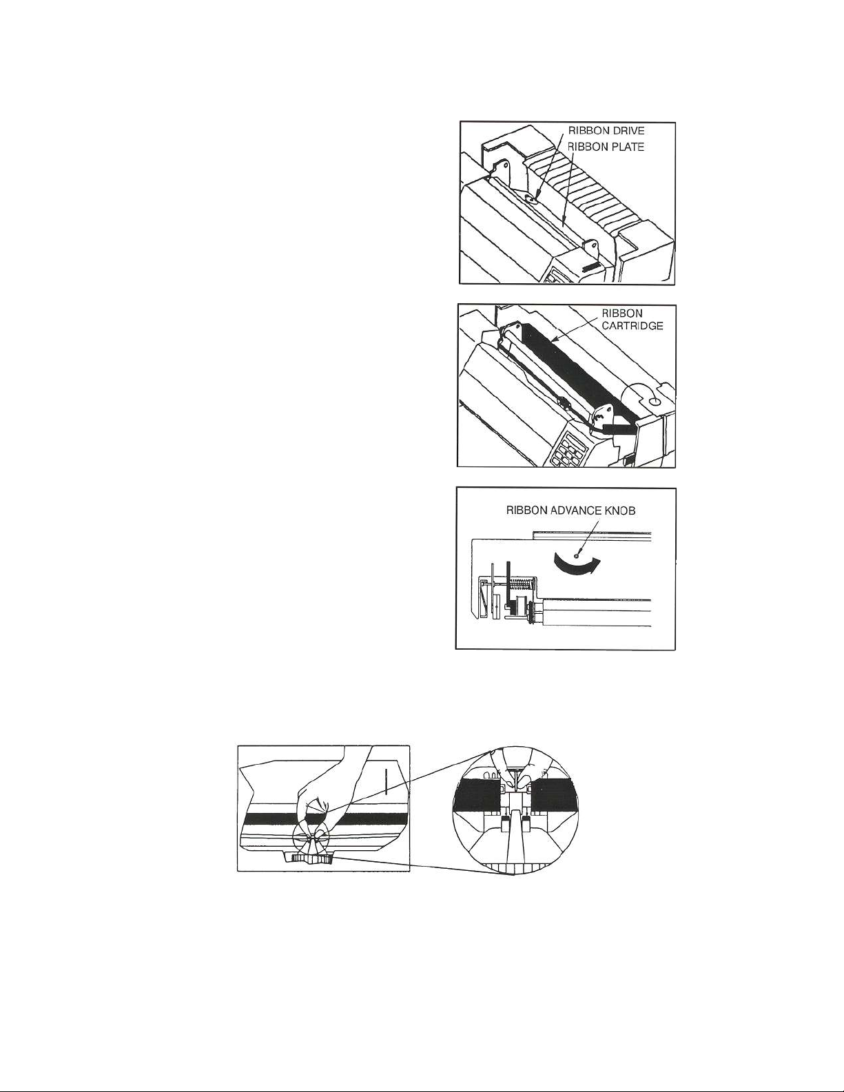
plate located in the area behind
the pinch rollers.
11. Lower the ribbon cartridge into
the printer. Ensure that the ribbon
loop is in front of the platen and
that the ribbon is not twisted. Press
the ribbon cartridge down onto
the ribbon plate.
12. If the ribbon cartridge does
not rest squarely on the ribbon
plate, rotate the ribbon advance
knob in the direction indicated
by the arrow on the cartridge
until the cartridge drops into
place on the ribbon drive.
13. Move the printhead to the center of the printer and place the ribbon guide on the printhead
nose. Push down on ribbon guide until it snaps into place.
1-11
14. Return the pinch roller to its normal position.
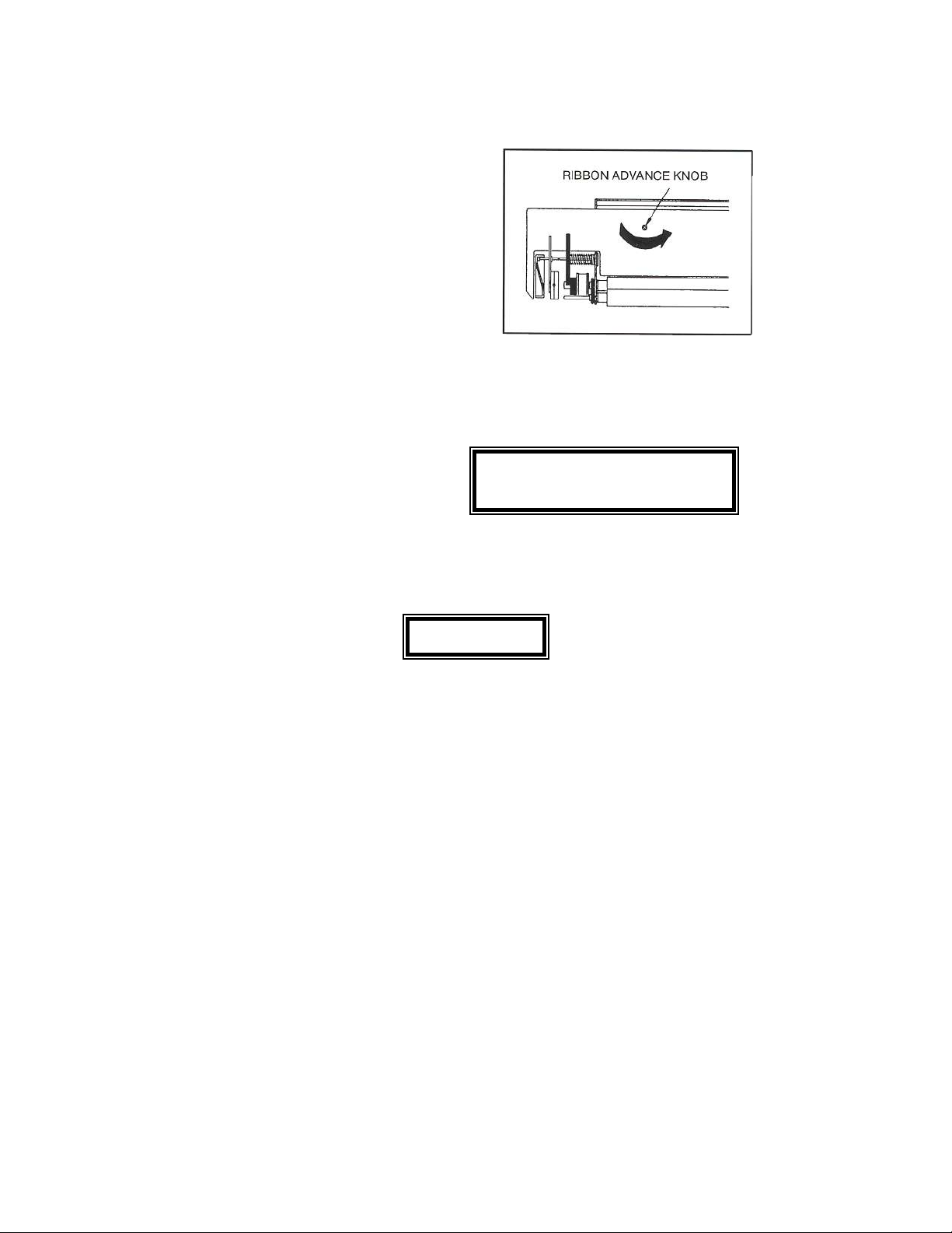
15. Remove any slack from the
ribbon by turning the ribbon
advance knob in the direction
of the arrow marked on the ribbon
cartridge.
16. Replace the tear bar. Make sure power is ON before closing the rear cover.
17. The following message should Ribbon Replaced?
appear in the Y=Setup N=On Line display.
18. Press Setup key to reset ribbon usage value. Refer to Appendix E for additional
information on Ribbon Life Monitor.
Make sure to reset Ribbon Life Monitor each time a new ribbon is installed.
Loading Forms
NOTE
Refer to Appendix E for information on Ribbon Life Monitor.
1-12
Refer to Chapter 2 for Forms Loading.
For instructions on Bottom Feed Path, see page 2-4.
For instructions on Front Feed Path, see page 2-9.
After paper is loaded in printer:
1. Set the power switch to ON.
2. After the printer initializes, press the Load/Park key to load paper.
3. Set right and left margins. See page 2-8
CAUTION
IMPROPER MARGIN SETTINGS CAN LEAD TO PRINTHEAD DAMAGE!!
DO NOT PRINT OVER TRACTOR HOLES OR OFF PAPER EDGE.
4. Refer to Forms Thickness Adjustment on page 2-13 prior to operating printer.
CAUTION
IMPROPER FORMS THICKNESS ADJUSTMENT
CAN DAMAGE THE PRINTHEAD!!
Printer Self -Test
1-13

This test is used to verify printer operation. Once started, it will continuously print the printer's
character set.
To start the test:
1. Press the Off Line key.
2. Press the Setup key to enter setup mode.
3. Press the Feature key once.
4. Press the Enter key.
When the Enter key is pressed, the printer will begin printing the test.
5. The self-test may be stopped by pressing the On/Off Line key.
Interfacing
1-14
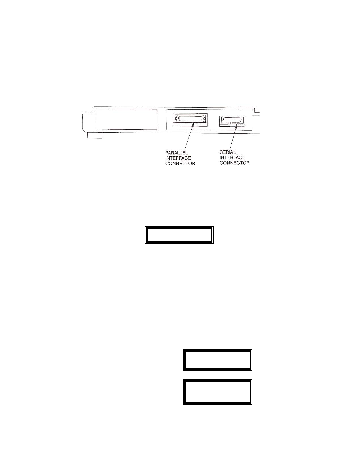
The three types of industry standard interfaces offered by the printer are: RS-232 serial interface,
RS-422 serial interface and TTL level 8-bit IBM/Centronics compatible, parallel interface. Serial
and parallel interface connectors are provided at the back of the printer. The 25-pin serial connector
is compatible for both RS-232 and RS-422.
Refer to the documentation for your computer to determine the type of shielded interface cable
needed and any unique pin-out configuration that may be required. This information should be
given to your dealer or distributor to determine the correct cable for your use.
WARNING
BEFORE CONNECTING THE CABLE, MAKE CERTAIN BOTH THE
HOST COMPUTER AND THE PRINTER ARE POWERED OFF.
Attach one end of the cable to the printer and the other end to the host computer. Secure the
interface cable to the interface connector with the screws or wire clips which are provided.
RS-232 And RS-422 Serial Interface Configuration
After installing the serial cable, you must configure the printer to use the serial interface. This is
done from the keypad.
1. Set the power switch to P1 Profile One
ON Font DPI0
2. Press the Off Line key. P1 Profile One
Font DP10
1-15
3. Press the Setup key. The G1 Forms Control
first group will appear on Form Length 66
the top line of the display
with the first feature of the
group appearing on the
bottom line.
4. Press the Group key until G4 Serial Ctrl
you have accessed Group Baud Rate 9600
4. The display will appear
as shown.
The printer is factory set for RS-232 serial interface. If you are using the RS-232 interface, proceed
to step 9. If you wish to select the RS-422 serial interface, proceed as follows:
5. Press the Feature key one time. G4 Serial Ctrl
Serial RS-232
6. Press the Value key to G4 Serial Ctrl
select RS-422. Serial RS-422
7. Press the Enter key to save G4 Serial Ctrl
your selection. Serial RS-422
Next, determine the baud rate of the host computer. The printer is factory set for 9600 baud. If the
baud rate for the printer must be changed, proceed as follows.
8. Press the Feature key G4 Serial Ctrl
one time. Baud Rate 9600
9. Press the Value key to G4 Serial Ctrl
select the desired baud Baud Rate 19.2K rate
(19.2K for this example).
Continue configuration of interface setup until proper host-printer communication is complete.
10. Press the Enter key to save G4 Serial Ctrl
your selection. Baud Rate 19.2K
1-16
11. Press the Setup key to Save Profile?

exit setup mode. The Y=Enter N=Setup
"Save Profide?"message
will be displayed.
12. Press the Enter key to save
the profile setting. P1 Profile One
Font DPIO
13. Press the On Line key to P1 Profile One
place the printer back on Font DPI0
line.
This page intentionally left blank
1-17
 Loading...