

AMT Datasouth M5DT Plus User Manual

Fastmark M5 Plus Series
Direct Thermal Barcode Printer
User’s Guide
Document #120523 Rev-A

Contents
1. Introduction..............................................................................................1
2. Getting Started.........................................................................................1
2.1 Unpacking and Inspection....................................................................1
2.2 Equipment Checklist ............................................................................1
2.3 Printer Parts.........................................................................................3
2.3.1 Front View .....................................................................................3
2.3.2 Rear View......................................................................................3
3 Setup..........................................................................................................3
3.1 Setting Up the Printer...........................................................................3
3.2 Loading Media Stock............................................................................4
3.3 Peel-Off Module Installation (Option) ...................................................6
3.4 Loading Labels for Peel-off Mode (Option)...........................................9
3.5 External Media Roll Mount Installation (Option).................................10
3.6 Cutter Module Installation (Option).....................................................12
3.7 Loading Media in Cutter Mode...........................................................15
3.8 Internal Ethernet Print Server Module Installation (Option)................16
3.9 Diagnostic Tool ..................................................................................20
3.9.1 Start the Diagnostic Tool..............................................................20
3.9.2 Printer Function (Calibrate, Ethernet setup, RTC setup…)..........21
3.10. Install Memory Card........................................................................21
4. Power on Utilities...................................................................................23
4.1 Gap/Black Mark Sensor Calibration...................................................23
4.2 Gap/Black Mark Calibration, Self-test, Dump Mode...........................24
4.3 Printer Initialization.............................................................................27
4.4 Black Mark Sensor Calibration...........................................................28
4.5 Gap Sensor Calibration......................................................................28
4.6 PAL application program....................................................................28
5. Maintenance...........................................................................................29
5.1 Cleaning.............................................................................................29
6. Troubleshooting.....................................................................................31
6.1 LED Status.........................................................................................31
6.2 Print Quality........................................................................................32
7. LED and Button Operation....................................................................33
7.1 LED....................................................................................................33
7.2 Button Operation................................................................................33
Revise History............................................................................................37
i

1. Introduction
Thank you for purchasing the AMT Datasouth M5 DT PLUS Direct Thermal Bar Code Printer .
Although the printer takes only a small amount of space, it delivers reliable, superior
performance.
This printer provides direct thermal printing at user selectable speeds of: 2.0, 3.0, 4.0 or 5.0
inches per second. It accepts roll feed, die-cut, and fan-fold labels for printing media. All
common bar codes formats are available. Fonts and bar codes can be printed in 4 directions,
8 different alphanumeric bitmap fonts and a build-in true type font capability. You will enjoy
high throughput for printing labels with this printer.
2. Getting Started
2.1 Unpacking and Inspection
This printer has been specially packaged to withstand damage during shipping. Please
carefully inspect the packaging and printer upon opening and prior to installation. Please
retain the packaging materials in case you need to reship the printer.
2.2 Equipment Checklist
Printer
User CD Disk (BarTender Ultralite, Printer User Manuals & Diagnostic Software)
Quick start guide
USB port cable
External universal switching power supply
Power Cord
Label Spindle
Fixing tab x2
1.5” core adapter x2
If any parts are missing, please contact the Customer Service Department of your
purchased reseller or distributor.
1

Optional Configurations
Peel off module assembly.
Guillotine cutter
Full cut:
Paper thickness: 0.06~ 0.19mm, 500,000 cuts
Partial cut:
Paper thickness: 0.06~0.12mm, 500,000 cuts
Paper thickness: 0.19mm 200,000 cuts
Main board integrated with internal Ethernet
Internal Ethernet print server module
Accessories
KP-200
KU-007 plus
External Ethernet print server
External wireless (802.11b/g) print server
External roll mount, media OD. 214 mm (8.4”) with 3” core label spindle
Contact CCD contact scanner
Long range linear image bar code scanner
2
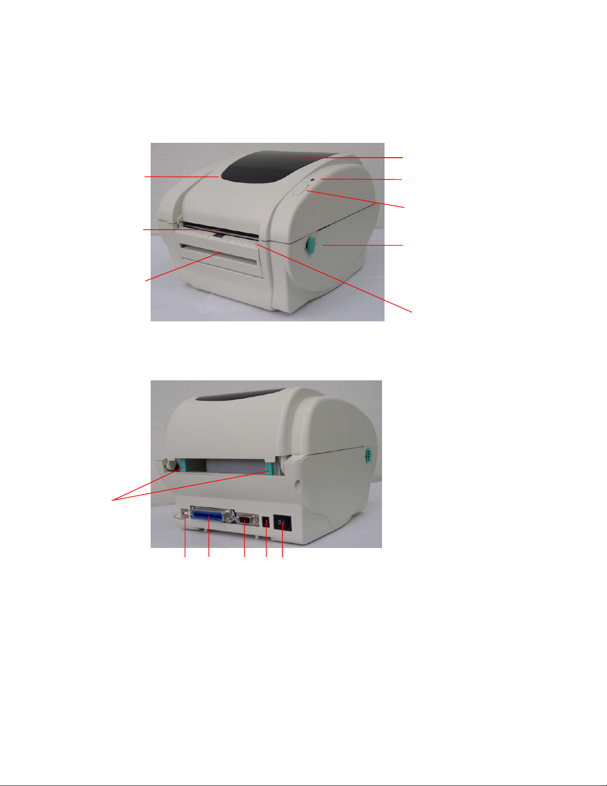
2.3 Printer Parts
2.3.1 Front View
Clear Window
Top Cover
Label Opening
Backing Paper Opening
2.3.2 Rear View
LED Indicator
Feed Button
Top Cover Open Lever
Front Panel
Fig.1 Top Front View
1. USB Interface
2. Centronics Interface
3. RS-232C DB-9 Interface
6
2
1
3
4
5
Fig.2 Rear View
3 Setup
3.1 Setting Up the Printer
1. Place the printer on a flat, secure surface.
2. Make sure the power switch is off.
3
4. Power Jack
5. Power Switch
6. Rear Label Guide
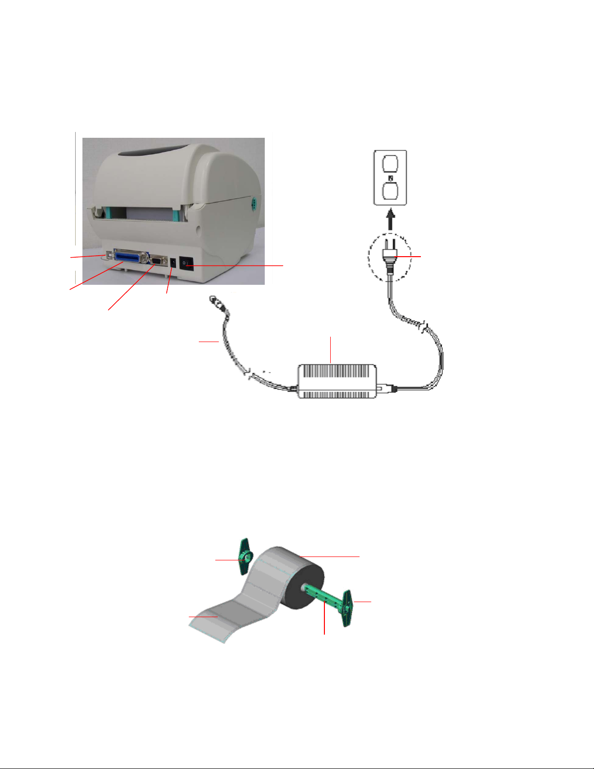
3. Connect the printer to the computer with the Centronics or USB cable.
r
4 Plug the DC power cord into the power jack at the rear of the printer, and then plug
the AC power cord into a properly grounded receptacle.
USB
Centronics
3.2 Loading Media Stock
1. Insert spindle into a media roll (If your media core is 1 inch, remove the 1.5 inch core
RS-232C
Power Jack
Power Cord
Fig. 5 Attach a power supply to a printer
adapter from the fixing tab).
Plug
Power Switch
Power Supply
1.5” Core Adapte
Printing Side Face up
1” Media Spindle
Media Roll
Fixing Tab
Fig 6 Media roll installation (I)
4
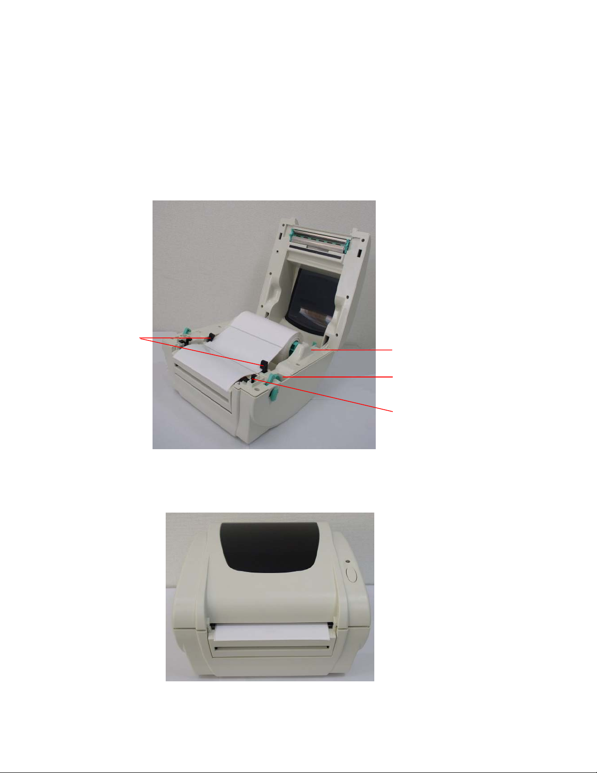
2. Open the printer’s top cover by releasing the green levers located on each side of the
printer and lifting the top cover.
3. Place a roll of media onto the internal Media Spindle.
4. Feed the media (printing side face up) under the Teflon bar and through the support
guides. The media should come to rest outside the printer. Refer to Fig #7.
5. Adjust the black center-biased media guides in or out by turning the adjustment knob so
they are slightly touching the edges of the media/backing.
Media Guide
Media Roll Mount
Adjustment Knob
Platen
Fig. 7 Media roll installation (II)
6. Close the printer top cover slowly and make sure the cover locks securely.
Note: Failure to securely close and lock the cover will result in poor print quality.
Fig. 8 Close the top cover completely
5

3.3 Peel-Off Module Installation (Option)
1. Open the top cover.
2. Remove the 6 screws in the lower inner cover.
Screws
3. Turn over the printer.
4. Remove two screws located near the top cover hinge.
Remove screw
Screws
Remove screw
6

5. Remove the screw at memory card cover.
6. Separate the top, inner, and the lower cover.
Screw
Lower inner
cover
Lower cover
7. Thread the cable red connector through the inner cover opening located near the front
of the printer. Insert the red cable connector into location JP17 (M5 DT) / JP19 (M5 DT
PLUS) on the main board. Install the peel-off module onto the lower inner cover slot.
7

Peel-off module
assembly
Install (2-places) one
side at a time.
8. Gently push the peel-off panel to lock onto the lower inner cover.
9. Reassemble parts in reverse procedures after installing the module.
8
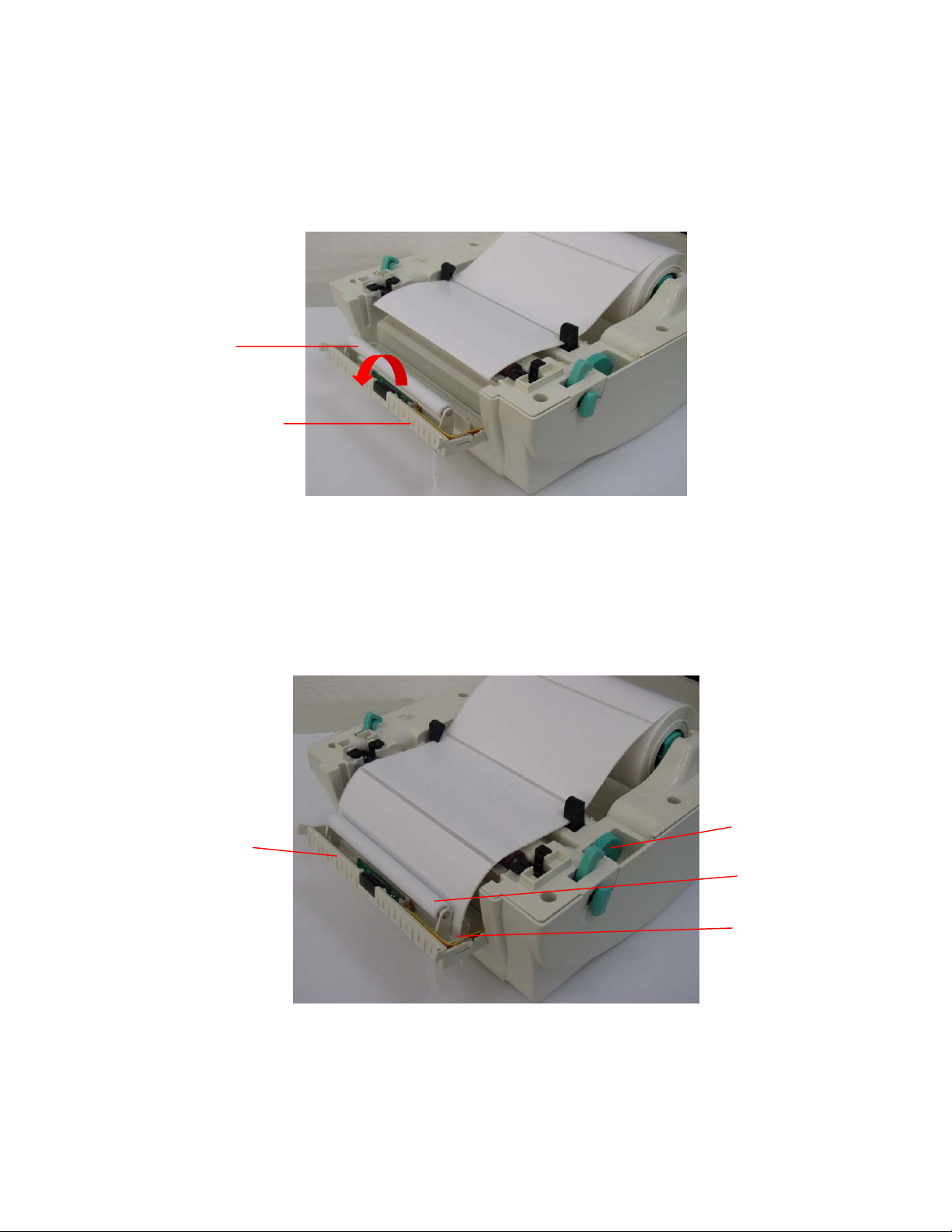
3.4 Loading Labels for Peel-off Mode (Option)
1. Open the peel-off module by pulling it forward.
Peel-off Roller
Peel-off Panel
Fig. 9 Open the peel-off panel
2. Thread the label, printing side facing up, through the support guides.
3. Thread the label through the liner opening, which is beneath the roller.
4. Adjust the black center-biased media guides by turning the adjustment knob to fit the
edge of the label/backing.
Adjustment Knob
Peel-Off Panel
Roller
Liner Opening
Fig. 10 Loading Labels for peel-off mode
5. Lift the peel-off panel up and back into the closed position.
9
6. Close the top cover.
Fig. 11 Label loaded completely in peel-off mode
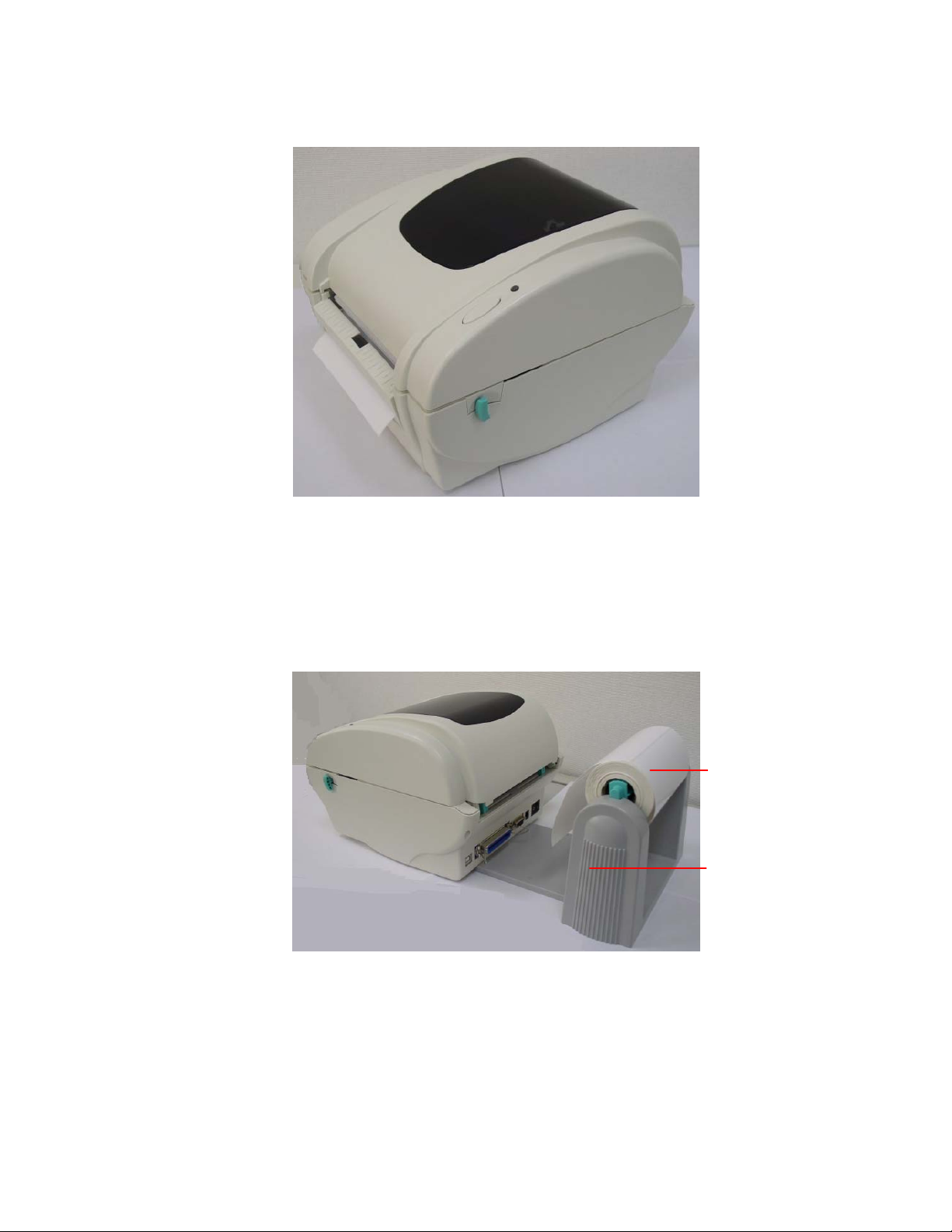
3.5 External Media Roll Mount Installation (Option)
1. Attach an external media roll mount on the bottom of the printer.
2. Install a roll of media on the external roll mount.
Fig. 12 External media roll mount installation (I)
Media
External Media
Roll Mount
10
 Loading...