

AMT Datasouth Journey II User Manual [en, de, es, fr, it]

User's Guide
II
Manual Part No. 107187
Rev. A


Safety and Agency Compliance
NOTICE
This Class A device complies with part 15 of the FCC rules and Canadian
ICES-003 rules. Operation is subject to the following two conditions:
1. This device may not cause harmful interference, and,
2. This device must accept any interference received, including
interference that may cause undesired operation.
This equipment has been tested and found to comply
with the limits for a Class A digital device, pursuant to
Part 15 of the FCC Rules. These limits are designed to
provide reasonable protection against harmful
interference when the equipment is operated in a
commercial environment. This equipment generates,
uses, and can radiate radio frequency energy and, if not
installed and used in accordance with the instructions,
may cause harmful interference to radio
communications. Operation of this equipment in a
residential area is likely to cause harmful interference, in
which case the user will be required to correct the
interference at his own expense.
i

When connecting the printer to a host computer system,
WARNING
always use shielded interface cables. The use of non-shielded
interface cables can violate the FCC emissions limits for a Class A
computing device. Do not leave unterminated interface cables connected to
the printer.
Any alteration or modification to this equipment may
cause non-compliance to:
UL safety standard 1950
CSA safety standard C22.2 No. 950
TÜV GS
EN60950
FCC regulations for Class A Computing Devices
Canadian ICES-003
EN55022-1 Class A Limits
EN50082-1
EN 61000-3-2
Contains UFST and Micro Type from Agfa Division, Bayer Corporation
Use, duplication or disclosure by the Government is subject to restrictions as set forth in the Rights in
Technical Data and Computer Software clause at FAR 252-227-7013, subdivision (b)(3)(ii) or
subparagraph (c)(1)(ii), as appropriate. Further sue, duplication or disclosure is subject to restrictions
applicable to restricted rights software as set forth in FAR 52.227-19 (c)(2).
ii

WARNING
The operator must disconnect the printer from the AC power supply before
performing any corrective action procedure that requires reaching into the
printer.
The printhead gets hot during use. Wait until the printhead is cool before
handling the printhead.
Changes or modifications to this unit not expressly approved by the party
responsible for compliance could void the user's authority to operate the
equipment.
Connecting this equipment to an ungrounded power receptacle can result in the
risk of electrical shock.
Make certain the printer is disconnected from the AC power supply before
reaching into the printer to perform any cleaning or maintenance task.
Intended for indoor use only.
AVERTISSEMENT
L’utilisateur devra débrancher cette imprimante de la prise d’alimentation en
CA avant toute intervention dans l’imprimante.
La tête de lecture chauffe lorsque l’imprimante est en marche. Attendre que la
celle-ci se soit refroidie avant toute manipulation.
Tout changement ou toute modification sur l’imprimante qui ne soit pas
expressément approuvé par la partie responsable en matière de conformité
pourra mettre fin aux droits de l’utilisateur d’utiliser ce matériel.
Le branchement de ce matériel à une prise d’alimentation électrique souterraine
peut provoquer une décharge électrique.
Veiller à ce que l’imprimante soit débranchée de la prise d’alimentation en CA
avant de réaliser des tâches de nettoyage ou d'entretien manuelles.
Ne jamais utiliser ce matériel à l’extérieur.
iii

ACHTUNG
Vor der Durchführung korrektiver Maßnahmen, die ein Hineingreifen in den
Drucker erforderlich machen, muß das Netzkabel für den Drucker abgezogen
werden.
Der Druckkopf heizt sich während des Betriebs auf. Vor dem Berühren des
Druckkopfs warten, bis er abgekühlt ist.
Dem Benutzer kann die Berechtigung zum Betrieb des Geräts entzogen werden,
falls er Änderungen an dieser Einheit durchführt, ohne die ausdrückliche
Zustimmung der Partei einzuholen, welche für die Einhaltung der relevanten
Richtlinien verantwortlich ist.
Wenn dieses Gerät an eine ungeerdete Steckdose angeschlossen wird, besteht
die Gefahr eines elektrischen Schlags.
Vor dem Hineingreifen in den Drucker zur Durchführung von Reinigungs- bzw.
Wartungsmaßnahmen sicherstellen, daß das Netzkabel für den Drucker
abgezogen ist.
Nur für Innenraum.
AVVERTENZA
L’operatore deve scollegare la stampante dalla rete prima di effettuare
qualsiasi procedura correttiva per cui sia necessario toccare all’interno la
stampante.
La testina si riscalda con l’uso. Attendere che la testina si raffreddi prima di
toccarla.
Eventuali cambiamenti o modifiche apportate a questa unità senza
l’approvazione esplicita da parte del responsabile per la conformità, può
annullare il diritto dell’utente di usare l’apparecchio.
Il collegamento di questa unità a una presa di corrente senza messa a terra può
risultare nel rischio di scossa elettrica.
Verificare che la stampante sia scollegata dalla rete prima di toccare le parti
interne della stampante a scopo di pulizia o manutenzione.
Prevista esclusivamente per l’uso al chiuso.
iv

ADVERTENCIA
Antes de que el operario realice cualquier reparación interna de la impresora,
deberá desconectarla del suministro de alimentación de CA.
La cabeza de la impresora se calienta durante su uso. Antes de tocarla deberá
esperar a que ésta se enfríe.
Cualquier cambio o modificación que se realice en esta unidad sin la
aprobación expresa en conformidad con la parte responsable, puede terminar
los derechos del usuario para operar el equipo.
Conectar este equipo a un suministro de alimentación subterráneo puede
provocar una descarga eléctrica.
Asegúrese de que la impresora está desconectada del suministro de
alimentación de CA antes de introducir la mano en su interior para realizar
cualquier labor de limpieza o mantenimiento.
Para uso interior solamente.
AVISO
O operador deve desconectar a impressora da fonte de energia antes de
executar qualquer procedimento de reparo que requeira acesso ao interior da
impressora.
O cabeçote de impressão esquenta durante o uso. Espere até que o cabeçote de
impressão esfrie antes de manuseá-lo.
Alterações ou modificações desta unidade sem autorização expressa da parte
responsável pela garantia técnica pode anular o direito do usuário de operar o
equipamento.
Conectar este equipamento a uma fonte de energia sem contato Terra pode
resultar em risco de choque elétrico.
Tenha certeza de que a impressora não está conectada a fonte de energia antes
de acessar o seu interior para executar qualquer tarefa de limpeza ou
manutenção.
Projetada somente para uso interno.
v

TABLE OF CONTENTS
Safety and Agency Compliance ...................................................................... i
SECTION 1 — INSTALLATION AND START UP...............................1
1.1 Introduction...............................................................................................1
1.2 Printer Specifications ...............................................................................2
1.3 Printer Parts..............................................................................................5
1.4 Quick Start-Up Procedure.........................................................................9
1.5 Unpack the Printer ..................................................................................11
1.6 Choosing a Location for the Printer........................................................11
1.7 Connect the Host and Itinerary RS-232 Cables.......................................15
1.8 Install the Power Cord............................................................................18
1.9 Loading and Removing Coupons ............................................................21
1.10 Printer Self-Test...................................................................................23
SECTION 2 — KEYPAD OPERATION............................................24
2.1 Keypad Configuration.............................................................................24
2.2 Placing the Printer On and Off line.........................................................25
2.3 Using the Reset/Clean Key.....................................................................26
2.4 Updating the Printer Software.................................................................27
2.5 Ready/Receive LED...............................................................................28
2.6 LCD Display...........................................................................................29
2.7 Key Functions.........................................................................................30
SECTION 3 — LOADING COUPON STOCK...................................32
3.1 Recommended Types and Sizes..............................................................32
3.2 Coupon Path............................................................................................33
3.3 Loading and Removing Coupons ............................................................34
SECTION 4 — MAINTENANCE AND TROUBLESHOOTING ...........40
4.1 Scheduled Maintenance and Cleaning.....................................................40
4.2 Error Messages.......................................................................................44
4.3 Printer Diagnostics.................................................................................53
4.4 Troubleshooting......................................................................................56
4.5 Troubleshooting Table............................................................................57
APPENDIX A — USER LEVEL KEYPAD DISPLAY MESSAGES.......59
APPENDIX B — SERVICE LEVEL KEYPAD DISPLAY MESSAGES .85
APPENDIX C — FEATURES AND PROFILES...............................104
C.1 Features................................................................................................104
C.2 Changing Features in a Profile.............................................................105
C.3 User Programmable Features...............................................................106
C.4 Profiles ................................................................................................114
C.5 Changing Profiles.................................................................................115
C.6 Configuring the Printer Using Profile Keys..........................................116
vi

TABLE OF FIGURES
Figure 1-1. External Printer Parts (Front View).................................................5
Figure 1-2. External Printer Parts (Back View)..................................................6
Figure 1-3. Internal Printer Parts (Side View)....................................................7
Figure 1-4. Output and Reject Bins (Front View)...............................................8
Figure 1-5. Loading Coupons into BIN 2 (acceptable methods).......................10
Figure 1-6. Printer Location.............................................................................14
Figure 1-7. Serial Interface Connections ..........................................................15
Figure 1-8. Power Supply Cord Selection........................................................20
Figure 1-9. Printer Self-Test.............................................................................23
Figure 2-1. Keypad Configuration....................................................................24
Figure 2-2. On line/Menu Key..........................................................................25
Figure 2-3. Reset/Clean Key............................................................................27
Figure 2-4. Ready/Receive LED ......................................................................28
Figure 2-5. Key Functions ................................................................................30
Figure 3-1. Coupon Path...................................................................................33
Figure 3-2. Loading Coupons ...........................................................................34
Figure 3-3. Loading Coupons — BIN 1............................................................35
Figure 3-4. Loading Coupons ...........................................................................36
Figure 3-5. Loading Coupons — BIN 2............................................................37
Figure 3-6. OUTPUT and REJECT BINS.........................................................39
Figure 4-1. Cleaning.........................................................................................41
Figure 4-2. Cleaning the Rollers.......................................................................42
Figure 4-3. Cleaning the Printhead ...................................................................43
Figure 4-4. BIN 1 .............................................................................................44
Figure 4-5. BIN 2 .............................................................................................45
Figure 4-6. ZONE 1..........................................................................................46
Figure 4-7. ZONE 2..........................................................................................47
Figure 4-8. ZONE 3..........................................................................................48
Figure 4-9. OUTPUT and REJECT BINS.........................................................51
Figure 4-10. OUTPUT and REJECT BINS.......................................................52
Figure C-1. Feature and Profile Keys.............................................................104
Figure C-2. Changing Features in a Profile.....................................................105
Figure C-3. Changing Profiles........................................................................115
vii

(Page is intentionally blank. Use for notes.)
viii
Section 1
Installation and Start Up
1.1 Introduction
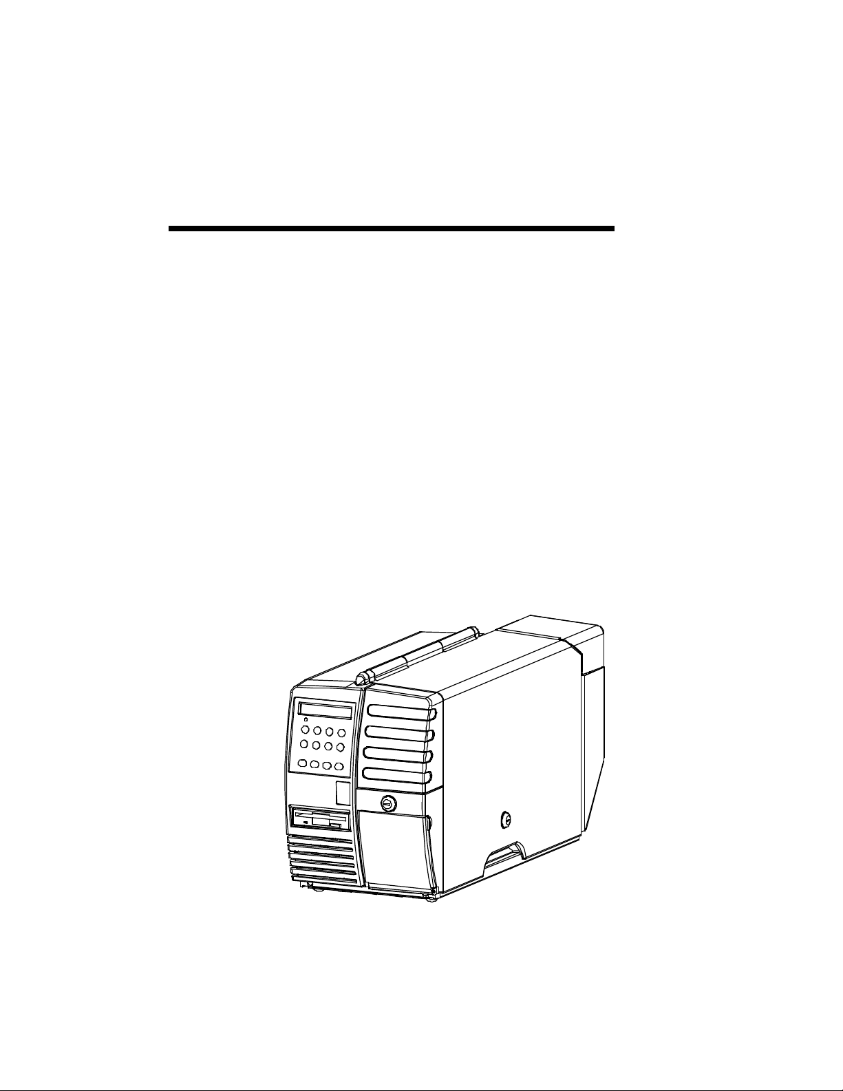
The Journey II Desktop ATB printer combines rugged durability and high
performance at a low cost, for ATB direct thermal ticketing applications at
travel agencies and satellite ticket printing (STP) locations. Communication
protocols and AEA emulation provide compatibility for existing applications
without host system code modifications.
Multiple PECTABS may be permanently stored in FLASH memory. A
companion itinerary printer serial port is provided. Ease of use is facilitated
with a 12-button color-coded keypad, preset profiles, instruction labels, quick
reference guides and a 2 by 24 display. The paper path, print head and
magnetics are easily accessed for cleaning. Continuous fan-fold stock and
conformance to IATA 722 and AEA specifications insure compatibility to
industry equipment. Direct thermal printing creates sharp, legible print, with
ticket stock being the only consumable.
1

1.2 Printer Specifications
PRINT TECHNOLOGY
• Direct Thermal
• 203 DPI (8 dots/mm)
• Adjustable Darkness Setting
• Simple Print Head Cleaning and Replacement
FONTS
• OCR B
• Letter Gothic 5, 10, 17
• Bold
SPEED
• Print Speed: 4 ips (102 mm/sec)
• Up to 15 Coupons Per Minute Throughput with Magnetic Write and
Verify (throughput varies, depending on unit configuration and print
condition)
• Up to 20 Coupons Per Minute Throughput without Magnetic Write
and Verify (throughput varies, depending on unit configuration and
print condition)
MAGNETICS
• IATA RP 1722 Res. 722e
• Four Tracks at 210 BPI
• Write, Write Verify
• SCN Read
2

DOCUMENT HANDLING
• Burst Fan-fold Stock
• Secure BIN 1 Stock Capacity of 500 Coupons
• External BIN 2 Stock Capacity of 1,000 coupons
• Secure Output Bin holds up to 200 Coupons, with Reject Bin that
holds up to 50 coupons (secured)
• Easy Access for Cleaning
COMMUNICATIONS
• COM 1 Port: RS-232C
• COM 2 Port: RS-232C (or optional parallel)
• Baud Rates: 1200, 2400, 4800, 9600, 14400, 19200, 38400, 57600
• Full Hardware and Software Handshaking
• Optional DTR control on Pin 11
• Multiple Host communication protocols available
• Modem Control Signals
OPERATOR PANEL
• Keypad: 12 Keys with Tactile Feedback
• Ready/Receive LED
• 2 x 24 Back Lit LCD Display
• Status, Messages, Error Codes and Setup Information Displayed
ENVIRONMENTAL
• Operating Temperature: 40°F to 104° F (5°C to 40°C)
• Storage Temperature: -4°F to 140°F (-20°C to 60°C)
• ESD: Contact ±4 kV, Air ±8 kV
COMPLIANCE
• Safety: UL 1950, CSA 950, TÜV GS Mark, CE Mark
• Emissions: FCC Class A, Canadian Standard ICES-003, CE Mark
3

LANGUAGES
• Standard Keypad Display Options include English, German, French,
Italian, Spanish, and Portuguese.
PROGRAMMING
• AEA ’94 / ’95
• Minimum of 8 PECTABS in Non-Volatile Memory (NVM).
• Re-programming via a standard 3.5” diskette or through flash
memory
POWER
• Auto Voltage Select
• 97V to 132V, 57Hz to 63Hz
• 195V to 264V, 47Hz to 53Hz
RELIABILITY
• Duty Cycle: 70 Coupons per Day
• MTBF: 25,000 hrs @ Rated Duty Cycle
• MTTR: 15 Minutes
PHYSICAL
• Size: 27.5 in.(L) x 10.5 in.(W) x 14.8 in.(H)
(698 mm x 267 mm x 376 mm)
• Weight: 55 pounds (25 kg)
• Color: Computer White
ADDITIONAL OPTIONS/CONSUMMABLES
• Printstand: P/N 107747
• Roller Cleaning Card: P/N 107831
• Printhead Cleaning Card: P/N 107832
4
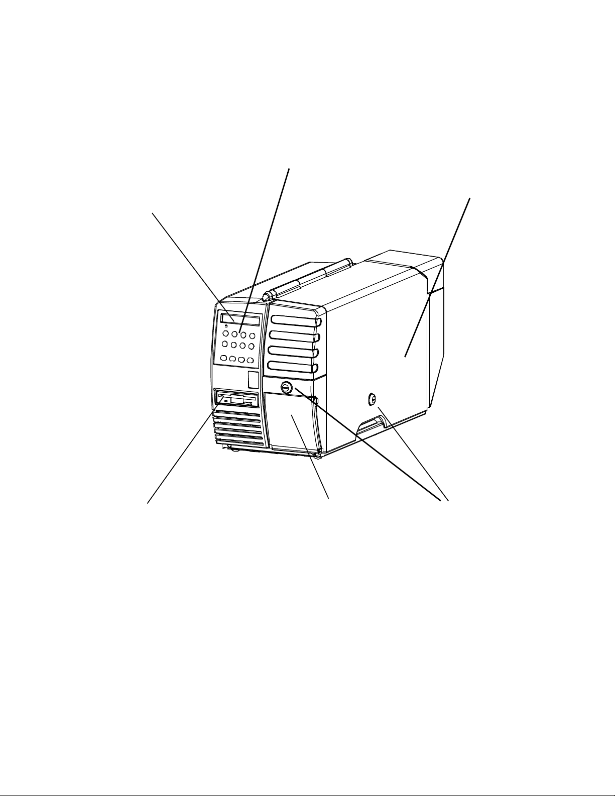
1.3 Printer Parts
The following illustrations highlight the major printer parts. Please become
familiar with these parts before continuing with installation and setup.
KEYPAD BIN 1
ACCESS
DOOR
DISPLAY
DISKETTE OUTPUT/REJECT KEY LOCKS
DRIVE BIN DOOR
Figure 1-1. External Printer Parts (Front View)
5

BIN 2
INPUT
SLOT
BIN 1
ACCESS
DOOR
FAN
COM 2
(OUTPUT)
PORT
BIN 2
INSTRUCTION
LABEL
COVER
LOCK
(on side)
POWER CORD
CONNECTION POWER
SWITCH
(on side)
COM 1
(INPUT)
PORT
Figure 1-2. External Printer Parts (Back View)
6
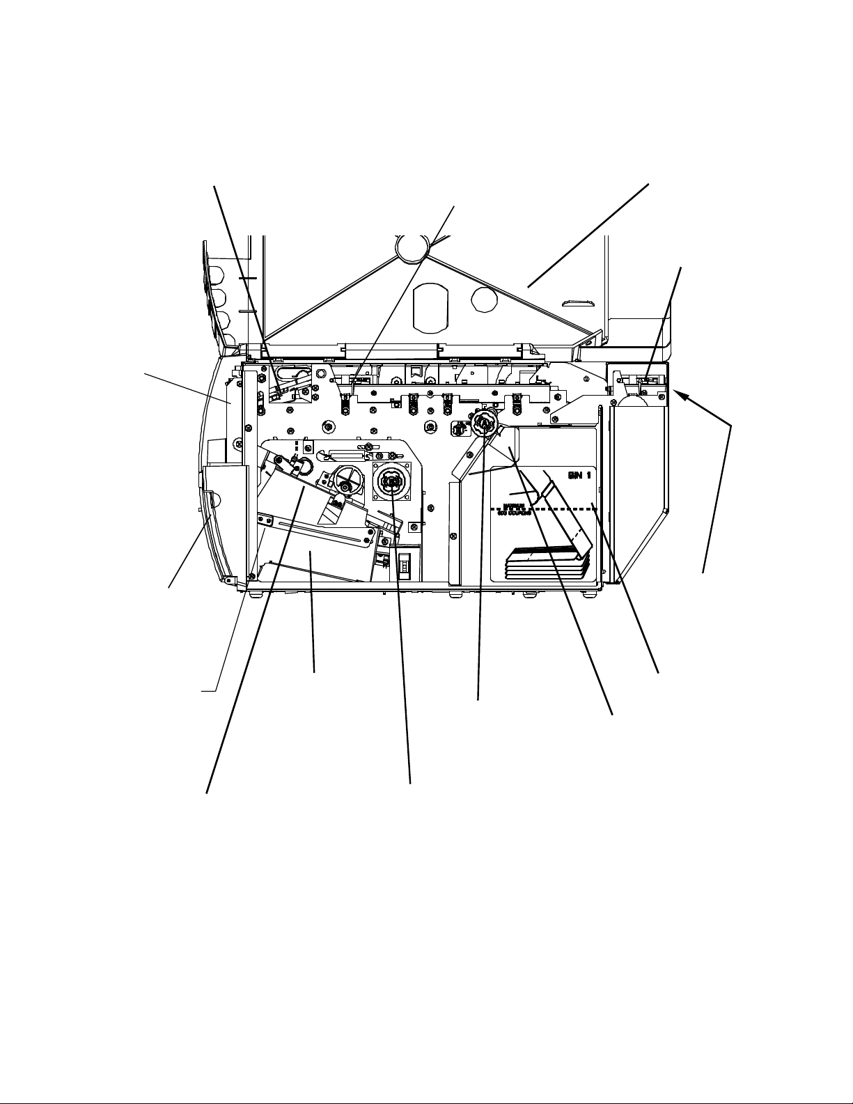
ZONE 2
LATCH
OUTPUT BIN)
(on back)
ACCESS
DOOR
ZONE 1 BIN 1
ACCESS ACCESS
PRINTHEAD DOOR AND DOOR
LATCH
ZONE 3
ACCESS
DOOR
AND
OUTPUT
BIN DOOR
REJECT BIN
LEVER
REJECT BIN
(located inside the
OUTPUT BIN
STOCK
LOAD
TRANSPORT
KNOB B
Figure 1-3. Internal Printer Parts (Side View)
7
BIN 1 INPUT
SLOT
BIN 2 INPUT
SLOT
BIN 1
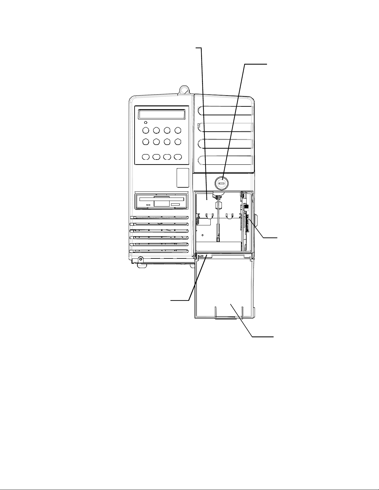
REJECT BIN
(drops down when lever
is depressed)
SECURITY
LOCK FOR
OUTPUT AND
REJECT BINS
OUTPUT BIN
Figure 1-4. Output and Reject Bins (Front View)
REJECT BIN
LEVER
OUTPUT
BIN DOOR
(shown open)
8

1.4 Quick Start-Up Procedure
The following abbreviated installation and start-up procedures are provided for
users already familiar with the Journey II Desktop product. If you are not
familiar with this printer, follow all of the instructions in Chapter 1 for setting
up the printer.
1. Unpack the printer using adequate assistance. Save the packing materials.
2. Choose a location for the printer with the following considerations:
• A level surface capable of adequately supporting printer weight.
• Near a grounded power receptacle.
• Adequate clearance: left side — 3 inches (80 mm),
right side — 11 inches (280 mm), top — 15 inches (380 mm),
back — 3 inches (76 mm) if BIN 2 coupons are on the floor (below the
printer) and 9 inches (230 mm) if BIN 2 coupons are on the desktop
(behind the printer).
• Away from excessive illumination; high and low temperature and
humidity; and dirt and dust.
3. Align the front base of the printer with the desktop edge to allow the
OUTPUT BIN DOOR to fully open and hang down out of the way. If the
optional printer stand is used, align the rubber feet on the bottom of the
printer with the holes on the top of the printer stand.
4. Connect and secure the host RS-232 serial connector to the printer’s COM1
serial port located on the back of the printer (the bottom connector).
5. Connect a grounded AC power cord to an AC wall receptacle and the
printer’s AC POWER CORD CONNECTOR located on the back of the
printer.
6. Using one of the keys provided, unlock the BIN 1 ACCESS DOOR located
on the right side of the printer.
7. Open the door completely until it rests on the left top side of the printer.
8. Load ATB ticket stock (maximum of 500 coupons) in the proper
orientation as shown on the BIN 1 instruction label located in the bin.
Gently square the coupon stock against the inside wall of the input bin.
(Coupons must match the document length set in the Profiles.)
9. Insert the staple tab or leading edge of the coupon stock into the BIN 1
INPUT SLOT with the side to be printed facing up.
10. Turn the green STOCK LOAD KNOB A one-quarter ( ¼ ) turn
counter-clockwise (as indicated on the label near the knob).
11. Close and lock the BIN 1 ACCESS DOOR and remove the key.
12. Power the printer on using the POWER SWITCH located on the left side
near the back. Move the switch to the 1 position (towards the front) to turn
on the printer.
13. Wait for the power up self test to complete. The top line of the keypad
display should show ‘On line:’ when complete.
9
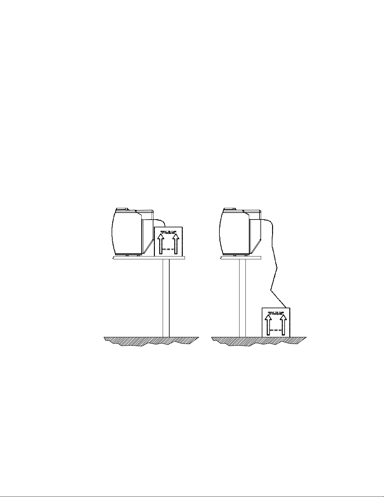
14. To load BIN 2, place a maximum of 1,000 coupons at the back of the
printer, directly behind and aligned with the BIN 2 INPUT SLOT. Orient
the coupons as shown on the BIN 2 label.
15. Insert the staple tab end or leading edge of the coupon squarely into the
document slot (with the print surface facing up). The BIN 2 INPUT SLOT
has a sensor that automatically detects and loads the document. (Both Bins
should now be loaded with coupon stock.)
16. Place the printer Off line by pressing the ON LINE/MENU key.
17. Press the FEATURE çç (left arrow) key until the ‘Print 1 Test Coupon’
message appears in the display.
18. Press the ENTER key.
19. One test coupon will print with a character ripple pattern (and magnetic test
pattern on the magnetic stripe if magnetics is enabled).
20. If no errors occurred during this test, the printer is ready for host
environment configuration.
21. Refer to the Troubleshooting section of the manual if an error occurs.
Figure 1-5. Loading Coupons into BIN 2 (acceptable methods)
10

1.5 Unpack the Printer
CAUTION
Remove the following from the shipping carton: Always use adequate lifting
assistance when removing the printer from the box.
U.S. Models: International Models:
Journey II Desktop Journey II Desktop
ATB Printer ATB Printer
Quick Start-up Quick Start-up
and Installation Guide and Installation Guides
Power Cord Display Overlays
Quick Reference Card Quick Reference Card
Keys (2) Keys (2)
Voided Tickets Voided Tickets
Cleaning Kit Cleaning Kit
Plastic Sleeve Plastic Sleeve
Save the shipping carton and all packing materials. These items are needed if
the printer is shipped for service.
SHIPPING THE PRINTER IN ANY CONTAINER OTHER
THAN IN ITS ORIGINAL PACKAGING MAY RESULT IN
SHIPPING DAMAGE.
1.6 Choosing a Location for the Printer
11
The printer weighs 55 pounds (25 kg) and should not be moved without
L’IMPRIMANTE.
ATTENTION
REAR EXHAUST VENT.
CAUTION
adequate assistance. To move the printer, grip the underside of the metal base.
Printer Size:
• Depth: 27.5 inches (698 mm)
• Width: 10.5 inches (267 mm)
• Height:14.8 inches (376 mm)
Additional space and location considerations are as follows.
Location:
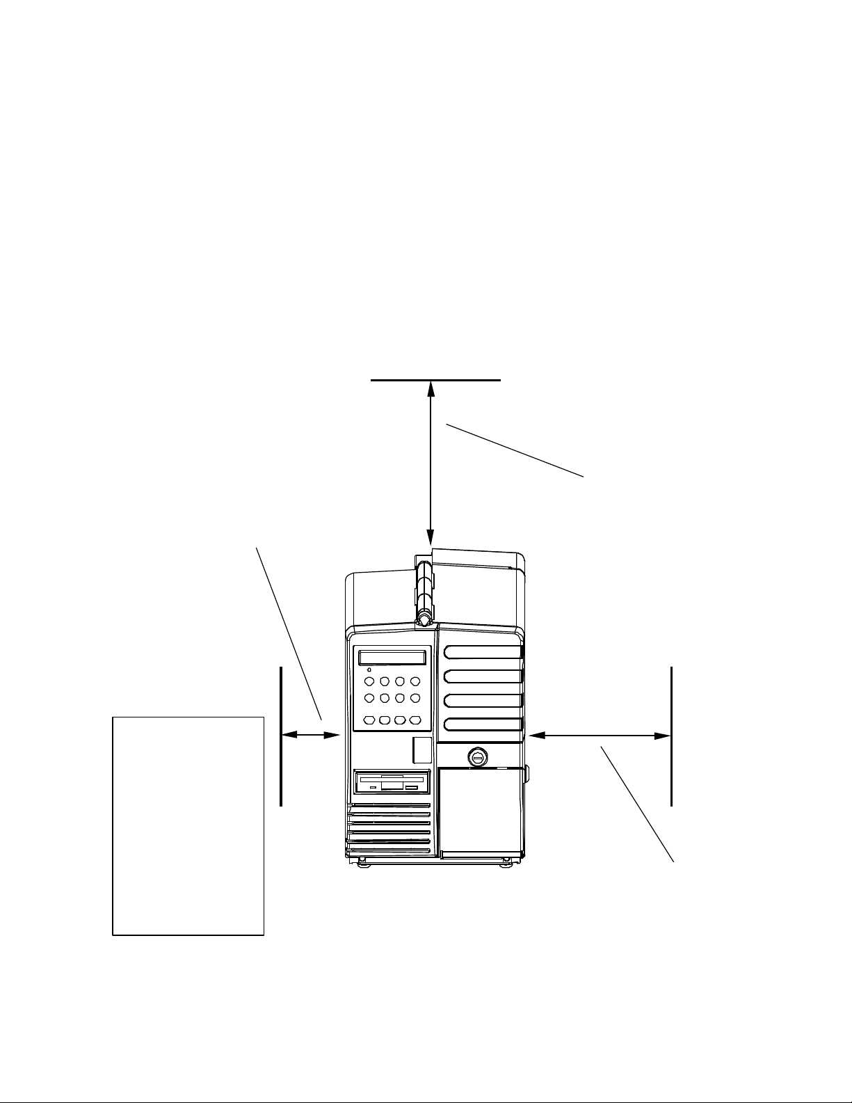
1. To allow for proper ventilation and access to the BIN 1 ACCESS DOOR,
BIN 2 INPUT SLOT, and the AC power switch, allow clearance on each
side of the printer as listed below (as viewed from the front of the printer):
Left Side:
Right Side:
Top:
Back:
(Back clearance depends on coupon placement.)
INCHES MILLIMETERS
3 80
11 280
15 380
3 or 9 80 or 230
TO AVOID HEAT BUILD-UP IN THE PRINTER,
DO NOT OBSTRUCT THE FRONT INTAKE VENT OR THE
NE PAS OBSTRUER LA PRISE D’AIR EXTERIEURE AVANT
OU LE CONDUIT DE SORTIE ARRIERE AFIN D’EVITER
TOUT ECHAUFFEMENT ACCUMULATIF DE
12

DIE ANSAUGÖFFNUNG VORN UND DIE ABLUFTÖFFNUNG
DRUCKERS ZU VERMEIDEN.
VORSICHT
STAMPANTE.
ATTENZIONE
PRECAUCIÓN
SUPER-AQUECIMENTO NO INTERIOR DA IMPRESSORA.
CUIDADO
HINTEN NICHT BLOCKIEREN, UM EIN ÜBERHITZEN DES
NON OSTRUIRE LA PRESA D’ARIA ANTERIORE O
L’APERTURA DI SFOGO POSTERIORE PER EVITARE
L’ACCUMULO DI CALORE ALL’INTERNO DELLA
PARA EVITAR LA ACUMULACIÓN DE CALOR EN LA
IMPRESORA, NO OBSTRUIR LA VÁLVULA DE ADMISIÓN
DELANTERA O LA VÁLVULA DE ESCAPE TRASERA.
NÃO OBSTRUA O VENTILADOR ANTERIOR OU O
EXAUSTOR TRASEIRO PARA EVITAR QUE OCORRA
2. Place the printer on a sturdy level surface and align the lower front edge of
the printer with the edge of the desk. This will allow the OUTPUT BIN
DOOR to hang straight down, out of the way, when open. The printer’s feet
should be approximately 1 inch (25 mm) from the edge of the desk.
(If you choose not to locate the printer on a desk, an optional printer stand is
also offered.)
3. Locate the printer near a grounded power receptacle and use the power
cord provided. (For international models, use only factory approved
power cords.) Do not use an extension cord to connect the printer.
13
Avoid the following:
(380 mm)
• Direct sunlight or excessively illuminated areas.
• Direct placement in front of air conditioning or heating vents.
• Extreme high or low temperatures.
• Exposure to excessive dirt or dust.
• Exposure to vibration or mechanical shock.
• Excessive humidity or condensation.
LEFT SIDE
CLEARANCE
OF 3 INCHES
(80 mm)
TOP
CLEARANCE
OF 15
INCHES
3 INCHES TO 9
INCHES (80 TO
230 mm)
REQUIRED FOR
REAR
CLEARANCE,
DEPENDING ON
COUPON
STOCK
Figure 1-6. Printer Location
14
RIGHT SIDE
CLEARANCE
OF 11 INCHES
(280 mm)
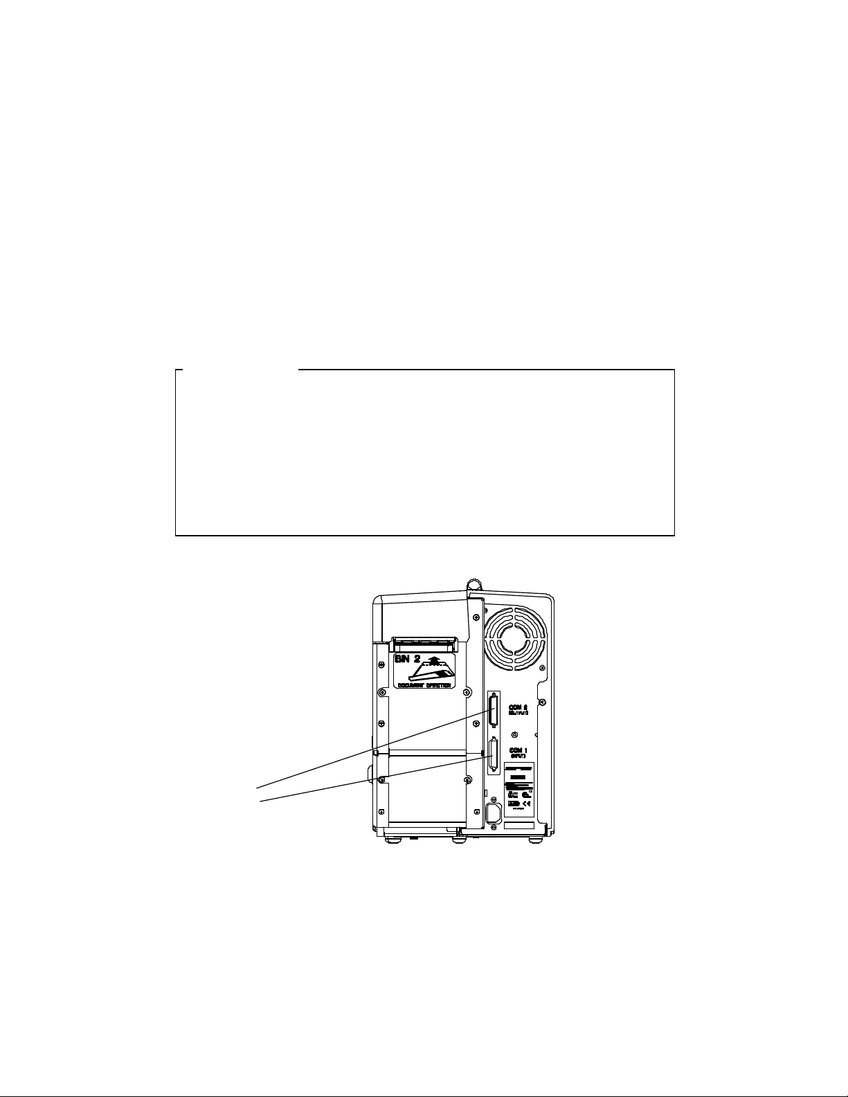
1.7 Connect the Host and Itinerary RS-232
Cables
Two RS-232 serial interfaces are provided on the Journey II Desktop unit.
COM 1 (INPUT) — the bottom connector — is used to connect to the host or
modem in STP environments. COM 2 (OUTPUT) — the top connector — is
provided to connect an itinerary printer in STP environments.
CAUTION
BEFORE CONNECTING THE CABLE, MAKE CERTAIN
BOTH THE HOST COMPUTER AND THE PRINTER ARE
POWERED OFF. THE USE OF CABLES LONGER THAN 15
FEET (4.5 m) THAT ARE NOT FACTORY APPROVED MAY
CAUSE INTERFACE COMPATIBILITY FAILURES AND ARE
INTERFACE
CONNECTIONS
(COM PORTS 1 AND 2)
Figure 1-7. Serial Interface Connections
15

Connecting COM1 (Input)
1. Connect your host or modem RS-232 cable to the port labeled COM1
(INPUT) — bottom connector — on the back of the printer.
2. Secure the connector with interface cable screws.
3. To automatically set the communication features, select the correct Profile
for your environment with the keypad. If changes are needed, refer to the
section on Features and Profiles.
COM1 (INPUT) port pin-out:
PIN SIGNAL
1 FG (Frame Ground)
2 TD (Transmit)
3 RD (Receive)
4 RTS (Ready To Send)
5 CTS (Clear To Send)
6 DSR (Data Set Ready)
7 SG (Signal Ground)
8 DCD (Data Carrier Detect)
20 DTR (Data Terminal Ready)
Connecting COM2 (Output) — STP Installations Only
1. Connect your itinerary printer RS-232 cable to the port labeled COM2
(OUTPUT) — top connector — on the back of the printer.
2. Secure the connector with interface cable screws.
3. To automatically set the communication features, select the correct Profile
for your environment with the keypad. If changes are needed, refer to the
section on Features and Profiles.
COM2 (OUTPUT) port pin-out:
PIN SIGNAL
1 FG (Frame Ground)
2 TD (Transmit)
3 RD (Receive)
5 CTS (Clear To Send)
7 SG (Signal Ground)
20 DTR (Data Terminal Ready)
6 DSR (Data Set Ready)
8 DCD (Data Carrier Detect)
16

Refer to the documentation for your computer to determine the type of shielded
interface cable needed and any unique pin-out configuration that may be
required.
17

1.8 Install the Power Cord
ATTENTION
CAUTION
The printer’s power supply is a universal input supply capable of operating
with any standard domestic and international AC power system. For user
safety and correct printer operation, the printer must be connected to a
properly grounded three-pin receptacle as specified by local codes and
ordinances.
Installing the power cord:
1. Set the POWER SWITCH located on the left side of the printer to OFF (0
position).
CONNECT THIS EQUIPMENT TO A GROUNDED POWER
RECEPTACLE ONLY. DO NOT CUT THE GROUND PIN
FROM THE PLUG. FAILURE TO PROPERLY GROUND THIS
PRINTER MAY RESULT IN AN ELECTRICAL SHOCK
HAZARD.
TOUJOURS BRANCHER CETTE UNITE A UNE PRISE
D’ALIMENTATION ELECTRIQUE AU SOL. NE PAS
COUPER LE CONTACT A LA MASSE DE LA FICHE. UNE
MAUVAISE MISE A LA TERRE DE L’IMPRIMANTE PEUT
PROVOQUER UNE ELECTROCUTION.
VORSICHT
DIESES GERÄT NUR AN EINE GEERDETE STECKDOSE
ANSCHLIESSEN. DEN ERDUNGSPOL NICHT AUS DEM
STECKER ENTFERNEN. BEI UNSACHGEMÄSSER ERDUNG
DES DRUCKERS BESTEHT BERÜHRUNGSGEFAHR.
18

ESTE EQUIPO DEBERÁ SER CONECTADO ÚNICAMENTE
PRECAUCIÓN
A UN SUMINISTRO DE ALIMENTACIÓN PUESTO A
TIERRA. NO CORTAR EL CONECTADOR A TIERRA DEL
ENCHUFE . SI LA IMPRESORA NO ES DEBIDAMENTE
CONECTADA A TIERRA PUEDE PROVOCAR UNA
DESCARGA ELÉCTRICA PELIGROSA.
ATTENZIONE
COLLEGARE QUESTO APPARECCHIO SOLAMENTE A
UNA PRESA DOTATA DI MESSA A TERRA. NON
TAGLIARE IL POLO DI MESSA A TERRA DELLA SPINA.
LA MANCATA MESSA A TERRA DI QUESTA STAMPANTE
PUÒ RISULTARE NEL RISCHIO DI SCOSSA ELETTRICA.
2. Attach the power cord to the printer’s AC POWER CORD CONNECTION
jack on the rear of the printer. Make certain that the cord is inserted as far
as possible into the connector jack.
3. Insert the plug (male) end of the power cord into a grounded AC outlet. A
grounded outlet must be used. Plugging the printer into an ungrounded
outlet may result in increased radio frequency noise generation, erratic
printer operation, or electrical shock. See the POWER SUPPLY CORD
SELECTION table for the correct power supply cord.
4. Set the POWER SWITCH to ON (1 position).
19

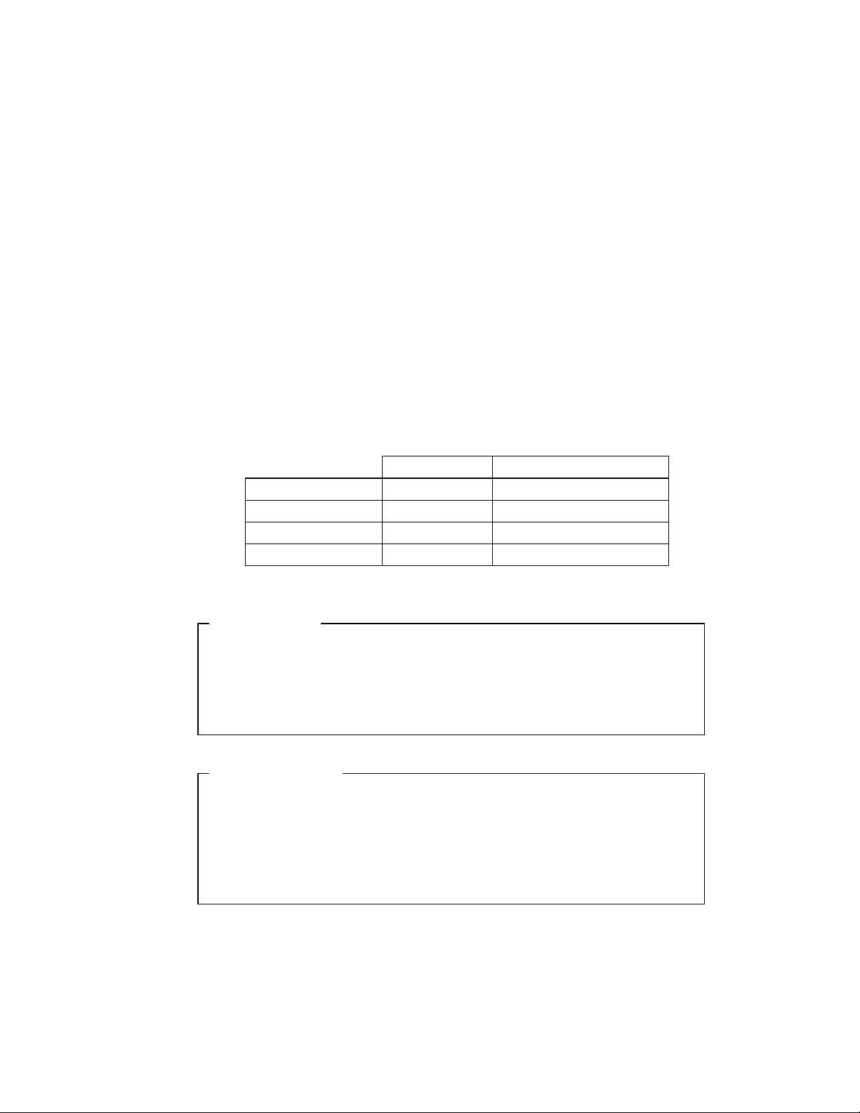
POWER SUPPLY CORD SELECTION
Use the following information to choose the proper power cord for your unit.
COUNTRY/VOLTAGE PLUG DESC. RECEPTACLE DESC. WIRE GAUGE OR SIZE
U.S.A./115V NEMA 5-15P IEC CEE-22 female 18 AWG minimum
U.S.A./230V NEMA 6-15P IEC CEE-22 female 18 AWG minimum
CONTINENTAL
EUROPE/230V
UNITED KINGDOM,
IRELAND
DENMARK Afsnit 107-2-01 IEC 320
SWITZERLAND SEV1011 IEC 320
AUSTRALIA,
NEW ZEALAND
INDIA BS546 IEC 320
ISRAEL SI 32 IEC 320
ITALY CEI 23-16/VII IEC 320
CEE7/7 IEC 320 0.75 sq. mm, HO5VV-F
BS1363 IEC 320
AS 3112 IEC 320 0.75 sq. mm, minimum
minimum, with “HAR”
marking
0.75 sq. mm, HO5VV-F
minimum, with “HAR”
marking
0.75 sq. mm, HO5VV-F
minimum, with “HAR”
marking
0.75 sq. mm, HO5VV-F
minimum, with “HAR”
marking
0.75 sq. mm, HO5VV-F
minimum, with “HAR”
marking
0.75 sq. mm, HO5VV-F
minimum, with “HAR”
marking
0.75 sq. mm, HO5VV-F
minimum, with “HAR”
marking
CHINA GB 1002 IEC 320 0.75 sq. mm, minimum
JAPAN MITI IEC 320 0.75 sq. mm., with Yukita
marking
Figure 1-8. Power Supply Cord Selection
20
 Loading...