

AMT Datasouth Fastmark 4000 User Manual
Fastmark 4000 Series
Barcode Label Printer
User’s Guide
Part No. 110121 A

IMPORTANT SAFETY INSTRUCTIONS
AND OTHER NOTICES
n This label printer complies with the requirements in Part 15 of FCC rules for a Class A
computing device. Operation of this equipment in a residential area may cause
unacceptable interface to radio and TV reception, requiring the operator to take whatever
steps are necessary to correct the interference.
n Place the printer on a flat, firm and solid surface.
n Do not place the printer near a heat source or near water.
n Refer to the specification label on the bottom of this printer and ensure that your power
source exactly meets these requirements.
n Do not open the printer during operation to avoid electrical shock.
n Do not attempt to disassemble this printer if it malfunctions.
n All rights are reserved. No part of this document may be reproduced or issued to third
parties in any form without the permission of AMT Datasouth.
n The material in this document is provided for general information and is subject to change
without notice.
TRADEMARK CREDITS
PCL is a registered trademark of Hewlett-Packard Company
Windows, MS-Word and MS-DOS are registered trademarks of Microsoft Corporation
PC is a registered trademark of International Business Machines
Centronics is a registered trademark of Centronics Corporation
CodeSoft is a registered trademark of Techniques Avancees
BarTender is a registered trademark of Seagull Scientific Systems, Inc.
LabelView is a registered trademark of Techniques Avancees
LabelMatrix is a registered trademark of StrandWare, Inc
User's Guide 1

CONVENTIONS
Some of the procedures in this guide contain special notices that highlight important
information:
Note Indicate information that you should know to help your
printer run properly and efficiently.
Caution Indicate guidelines that, if not followed, can cause
damage to equipment.
Warning Indicate a situation where there may be a danger to you.
Important Indicate that the associated material needs to be done to
ensure proper printer operation.
The use of the term's right and left assume that you are looking at the
front of the printer.
TECHNICAL SUPPORT
Please contact your local dealer first for technical support. Your dealer is knowledgeable
about driver installation, application software and general printer operation. If you still need
factory technical support after contacting your dealer, you may mail any problems through the
E-mail account, “www.amtdatasouth.com”. You can also get the most updated driver or
application from the web site “http://www.amtdatasouth.com”.
© Copyright 2001 by AMT Datasouth Corporation
First Edition: April 2001
2 User's Guide

Table of Contents
PRODUCT DESCRIPTION ....................................................................................... 7
OVERVIEW 8
UNPACKING AND INSPECTION............................................................................ 9
INSTALLATION AND CONFIGURATION .......................................................... 10
Setting up the Printer ................................................................................................ 10
Connecting the Power Cord ..................................................................................... 12
Connecting the Printer to Your Host ......................................................................... 13
Loading the Ribbon.................................................................................................. 15
Loading Media......................................................................................................... 19
Changing Position of the Media Supply Spindle......................................................... 24
Calibrating Media Sensors........................................................................................ 25
Performing the Self Test............................................................................................ 26
Resetting the Printer to Factory Default Settings ........................................................ 31
PANEL OPERATION ............................................................................................... 33
Front Panel.............................................................................................................. 33
LCD Display (FM4602 and 4603 models only) ........................................................ 37
Front Panel Set-up Menu ......................................................................................... 39
Procedure to Enter into Set-up Mode....................................................................... 40
Set-up Mode Selection Items ................................................................................... 41
Setting Display Language.......................................................................................... 43
Back Panel............................................................................................................... 44
Back Panel Switches (FM4602 and FM4603 models only)....................................... 46
PS/2 Keyboard I/F (FM4602 and FM4603 models only)......................................... 48
COMMAND QUICK REFERENCE....................................................................... 49
Command Set for PPLA .......................................................................................... 49
Command Set for PPLB........................................................................................... 57
PRINTER DRIVER .................................................................................................. 61
Driver Installation..................................................................................................... 62
How to Use the Driver ............................................................................................. 63
TROUBLESHOOTING AND MAINTENANCE ................................................... 69
Troubleshooting........................................................................................................ 69
Recovery................................................................................................................. 71
Preventive Maintenance............................................................................................ 72
User's Guide 3

Appendix A: Printer Specifications ........................................................................... 75
General Specifications .............................................................................................. 75
Fonts, Bar Codes and Graphics................................................................................ 76
Optional Accessories................................................................................................ 77
Appendix B: INTERFACE SPECIFICATIONS ...................................................... 79
Introduction ..............................................................................................................79
Serial....................................................................................................................... 79
Parallel (Centronics)................................................................................................. 82
Auto Polling ............................................................................................................. 82
Appendix C: PRINTER STATUS ............................................................................. 83
Appendix D: ASCII TABLE...................................................................................... 84
Appendix E: FONTS AND BAR CODES FOR PPLA ............................................ 85
Internal Fonts........................................................................................................... 85
Courier Font Set ...................................................................................................... 90
Internal Bar Codes................................................................................................... 94
Appendix F: FONTS AND BAR CODES FOR PPLB............................................. 99
Internal Fonts........................................................................................................... 99
Internal Bar Codes................................................................................................. 103
Appendix F: STAND-ALONE OPERATION FOR KEYBOARD AND BARCODE
READER ........................................................................................... 105
Keyboard .............................................................................................................. 105
Barcode Reader..................................................................................................... 109
4 User's Guide

Table of Figures
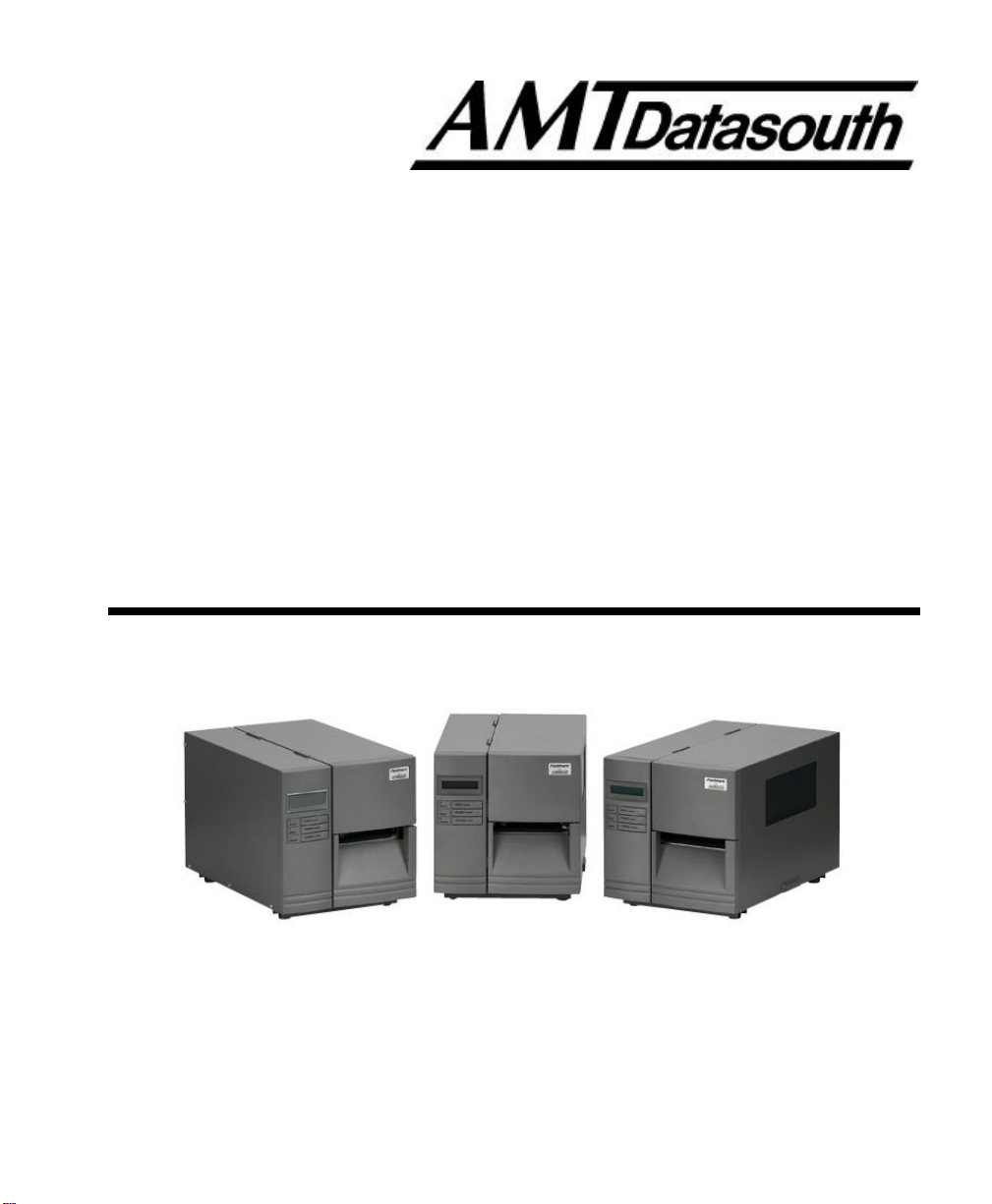
Figure 1 - Fastmark 4000 Series Printer..............................................................................7
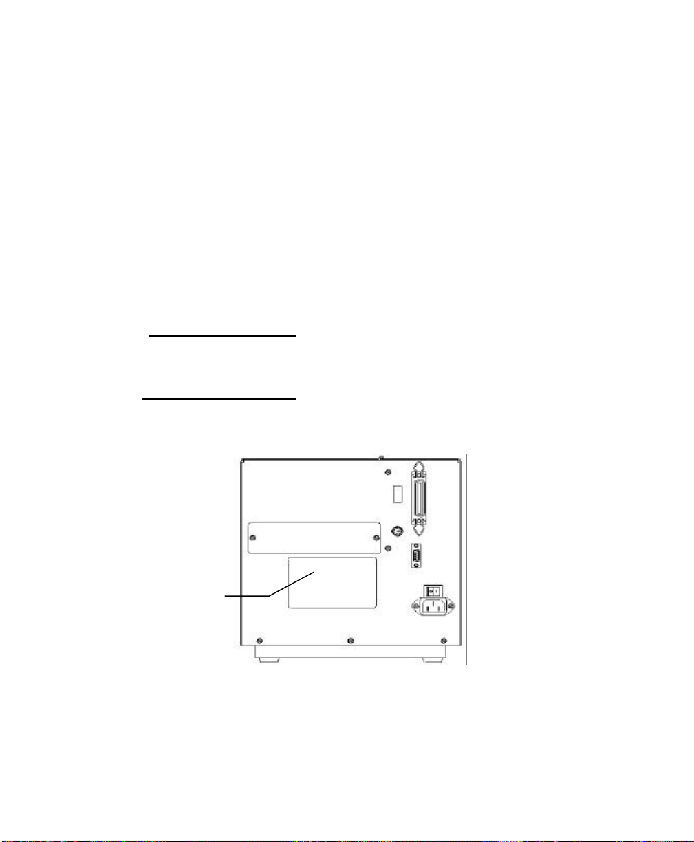
Figure 2 - Model and Serial Number Location .....................................................................8
Figure 3 - Shipped with Printer...........................................................................................9
Figure 4 - Front and Side View........................................................................................ 10
Figure 5 - FM 4402 Back Panel....................................................................................... 11
Figure 6 - FM 4602 and 4603 Back Panel......................................................................... 11
Figure 7 - Power Cord Connection ...................................................................................12
Figure 8 - Communication Cable ...................................................................................... 13
Figure 9 - Open Media Access Cover.............................................................................. 15
Figure 10 - Printhead Latch and Side Access Cover.......................................................... 16
Figure 11 - Ribbon Take-Up Core ....................................................................................16
Figure 12 - Ribbon Routing.............................................................................................. 17
Figure 13 - Open Media Access Cover ............................................................................ 19
Figure 14 - Printhead Latch and Side Access Cover.......................................................... 20
Figure 15 - Outside Media Guide ......................................................................................21
Figure 16 - Media Sensor Adjust Knob .............................................................................22
Figure 17 - Media Routing............................................................................................... 23
Figure 18 - Media Spindle Location.................................................................................. 24
Figure 19 - Self Test FM4602/FM4603 PPLA .................................................................. 27
Figure 20 - Self Test FM6402/FM4603 PPLB................................................................... 28
Figure 21 - Self Test FM4402 PPLA................................................................................ 29
Figure 22 - Self Test FM4402 PPLB ................................................................................30
Figure 23 - Fastmark 4000 Series Front Panel................................................................... 33
Figure 24 - Entering into Set-up Mode .............................................................................. 40
Figure 25 - Back Panel FM4602/FM4603......................................................................... 45
Figure 26 - Back Panel FM4402 ...................................................................................... 45
Figure 27 - Printhead (TPH) Maintenance ........................................................................72
User's Guide 5

This page is blank
6 User's Guide
PRODUCT DESCRIPTION
This label printer is a high-performance, low-cost Direct Thermal/Thermal Transfer labeling
system. Its user-friendly design and affordable price set a new standard for the Desktop
Label Printer in retail, office and industrial applications.
The printer is designed with the most efficient memory management technology - True Speed
and prints at a speed of 1 to 6 inches per second. When bundled with its smart printer driver,
the user can easily print out bar codes, texts and graphics from any editing application (e.g.
CodeSoft, BarTender) under Windows 95/98/2000, and NT. All popular bar codes and fonts
are resident in the printer memory to handle versatile applications.
The solid designed mechanism allows quick and easy media (paper) and ribbon loading. The
optional Peel and Present with Internal Rewind and Cutter provide alternatives of fan-fold
label and continuous paper handling.
This printer is a compact, highly integrated, high performance and high resolution on-site
labeling system.
The User’s Manual will help you understand basic operations of the printer such as set-up,
installation, configuration and maintenance. Before reading the manual you should first
identify your printer model. The printer model name is located on the back of the printer on its
product label.
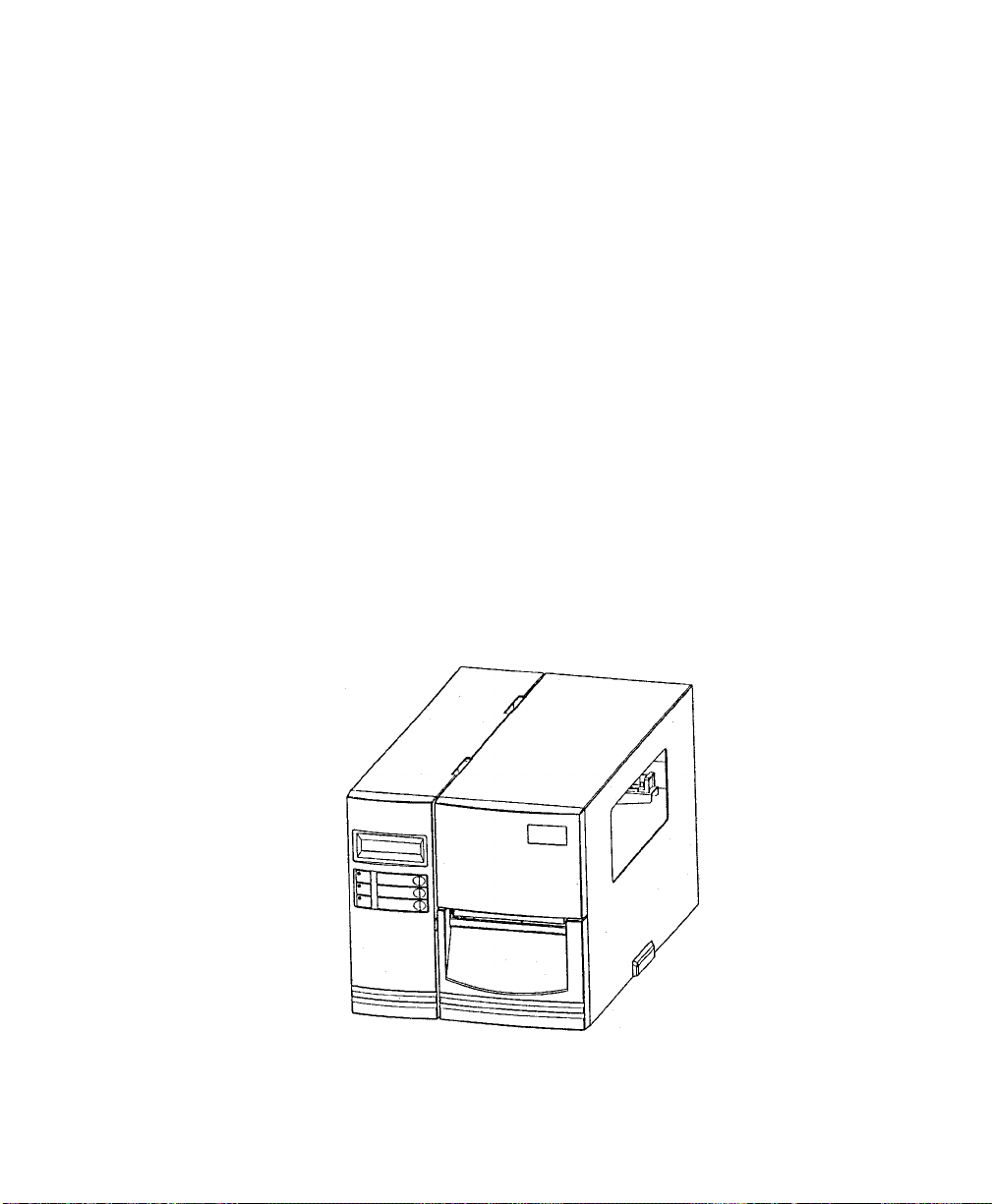
Figure 1 - Fastmark 4000 Series Printer
User's Guide 7
OVERVIEW
The Fastmark FM4000 series is currently comprised of 3 models:
• FM4402
• FM4602
• FM4603
While these models are similar in many ways, important differences exist. Throughout this manual
instructions and illustrations applying to a particular model will be labeled accordingly otherwise the
instructions apply to all models.
NOTE: The model number is printed on the compliance label attached to the
back of the printer. After un-packing please record the model number
below for reference.
MODEL No:
SERIAL No:
8 User's Guide
Model No: and
Serial No:
Figure 2 - Model and Serial Number Location
UNPACKING AND INSPECTION
This section is provided to assist you in taking the printer from the shipping container to the
application environment and ready for use.
1. Remove top foam packing piece.
2. Lift printer straight up out of box carefully with adequate assistance.
3. Remove accessory kit and supplies.
4. Remove printer from plastic bag.
NOTE: Save box and all packing materials for future use, in the event the printer
needs to be shipped.
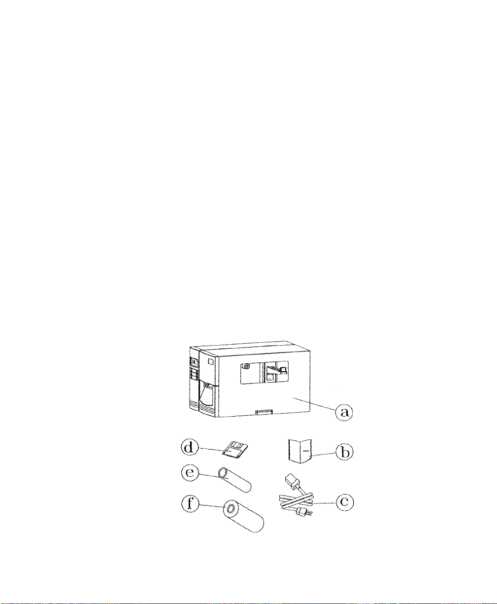
Verify that the printer box contains the following materials when unpacking:
a. Printer
b. User’s Manual
c. Power cord
d. Diskette(s) or CD for Windows 95/98/2000/NT and Label Design Software
e. Take up Core
f. A ribbon roll and a take-up ribbon core.
g. A media roll (not pictured)
Figure 3 - Shipped with Printer
User's Guide 9

INSTALLATION AND CONFIGURATION
Setting up the Printer
Before setting up the printer you should first consider the following:
• Flat stable surface with sufficient clearance to allow for interface cables and media
loading.
• Free from excessive direct sunlight, temperature, humidity, dust, dirt, and debris.
• Near a grounded AC power receptacle wired in compliance with local ordinances.
Media Viewing
LCD
(FM4602 / FM4603
ONLY)
FEED / CONFIG.
PAUSE / CALIBR.
CANCEL / RESET
10 User's Guide
Media Exit
Figure 4 - Front and Side View
Media Access Cover
Front Access Door
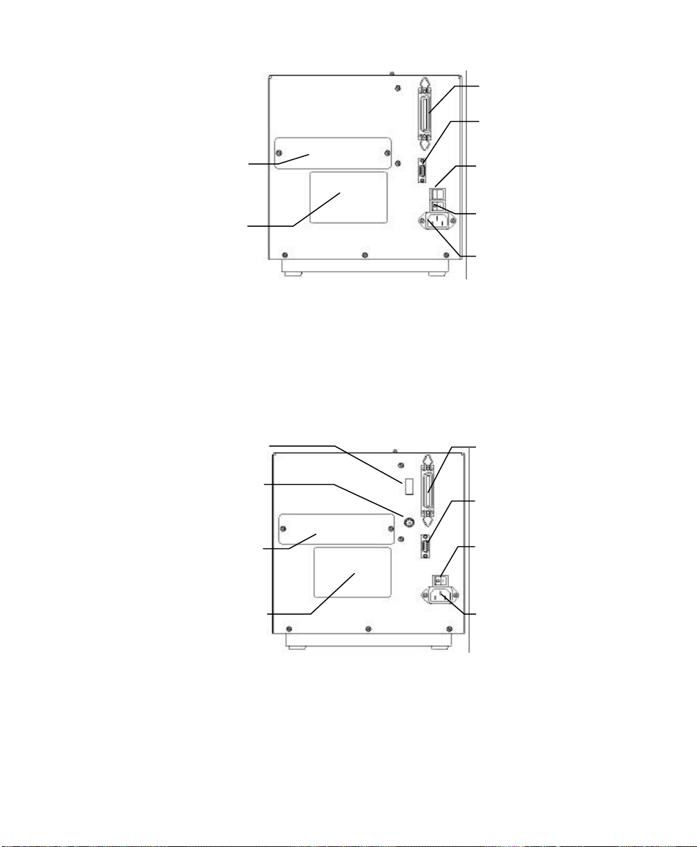
Parallel Port
Serial Port
External Label
Feed Slot Cover
Model No. and
Serial No.
Switches Parallel Port
PS/2, Keyboard
Interface
External Label
Feed Slot Cover
AC Voltage
Select Switch
Power Switch
AC Inlet
Receptacle
Figure 5 - FM 4402 Back Panel
Serial Port
Power Switch
Model No. and
Serial No
Figure 6 - FM 4602 and 4603 Back Panel
AC Inlet
Receptacle
User's Guide 11
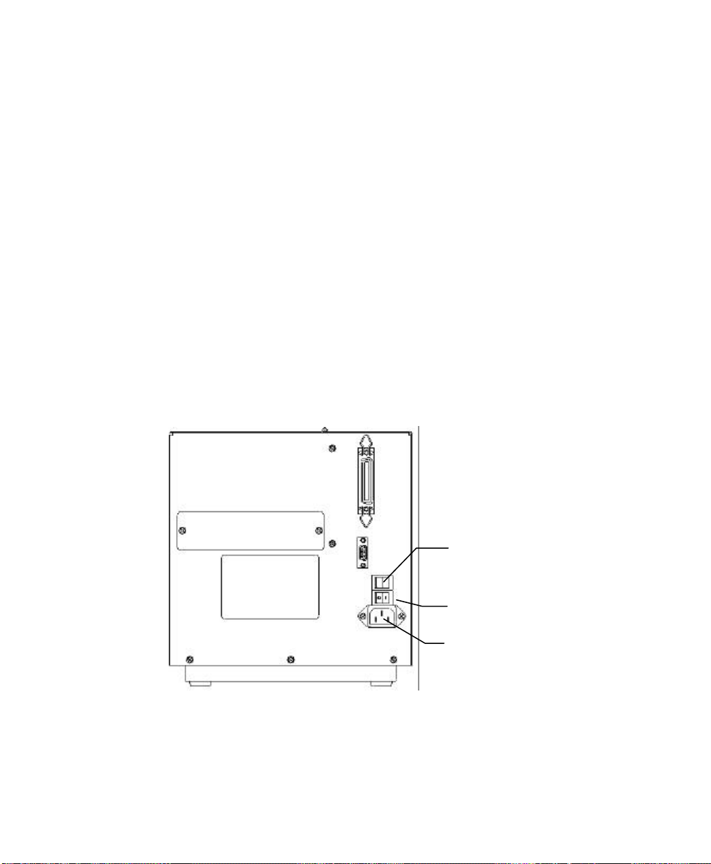
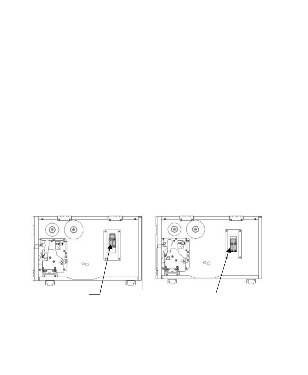
Connecting the Power Cord
1. Ensure printer Power Switch is off "0".
2. IMPORTANT: (FM4402 ONLY) Ensure the AC Voltage Select Switch is set to the
correct Voltage for this installation.
3. Remove the yellow voltage setting label from the AC Inlet Receptacle.
4. Connect the power cord to the AC Inlet Receptacle located on the back of the printer.
5. Connect AC power plug to a suitable AC source.
6. Connect either Centronics Parallel cable or RS-232 Cable.
CAUTION (FM4402 ONLY): Failure to properly set the AC
Voltage Select Switch will cause damage to the printer and will
Void the warranty. Ensure this is set properly before connecting
the AC power cord.
12 User's Guide
AC Voltage Select Switch
(FM4402 ONLY)
Power Switch
AC Inlet Receptacle
Figure 7 - Power Cord Connection

Connecting the Printer to Your Host
1. You can connect the printer with any standard Centronics cable to the parallel port of the
host computer.
2. Or, you can connect the printer with a serial cable to the RS-232C port of your computer
or terminal. (For PC compatibles, the RS-232C port is COM1, COM2 or COM3.)
Note: Using Centronics allows for a much higher communication speed
than serial.
Figure 8 - Communication Cable
3. If you use the serial port with your own cable, refer to the Appendix A and check the pin
connection. Be sure that the speed (baud rate) and protocol are the same between printer
and host.
Caution: Pin 9 on the serial port is directly connected to +5volts DC. It
is suggested that this pin be not connected in your cable, unless
required.
To change the Baud Rate:
FM4402: Send the <STX>KI8n command to the printer. See the System
Setting Commands section for more details.
FM4602/4603: The switches on the back control Baud Rate. See the Back
Panel Switches section for more details
User's Guide 13

The factory default parameters of serial port are:
Speed (baud rate) 9600
Data format 1 start bit, 8 data bits and1 stop
bit.
Parity None
Handshaking (Flow control) XON/XOFF as well as RTS/CTS
Note: It is not necessary to set a switch or send a command for the
parallel and serial port selection. The printer automatically detects
the active port.
Print a SELF-TEST to review serial settings.
14 User's Guide

Loading the Ribbon
Thermal Transfer Media only
If Direct Thermal Media is used, skip to the section Loading Media.
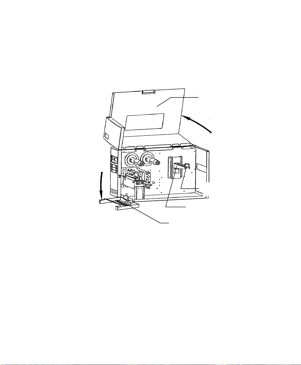
1. Open the Media Access Cover by lifting it up until it rests upon the top of the printer.
2. Open the Front Access Door by rotating it down.
Media Access Cover
Media Supply Guide
Media Supply Spindle
Front Access Door
Figure 9 - Open Media Access Cover
User's Guide 15
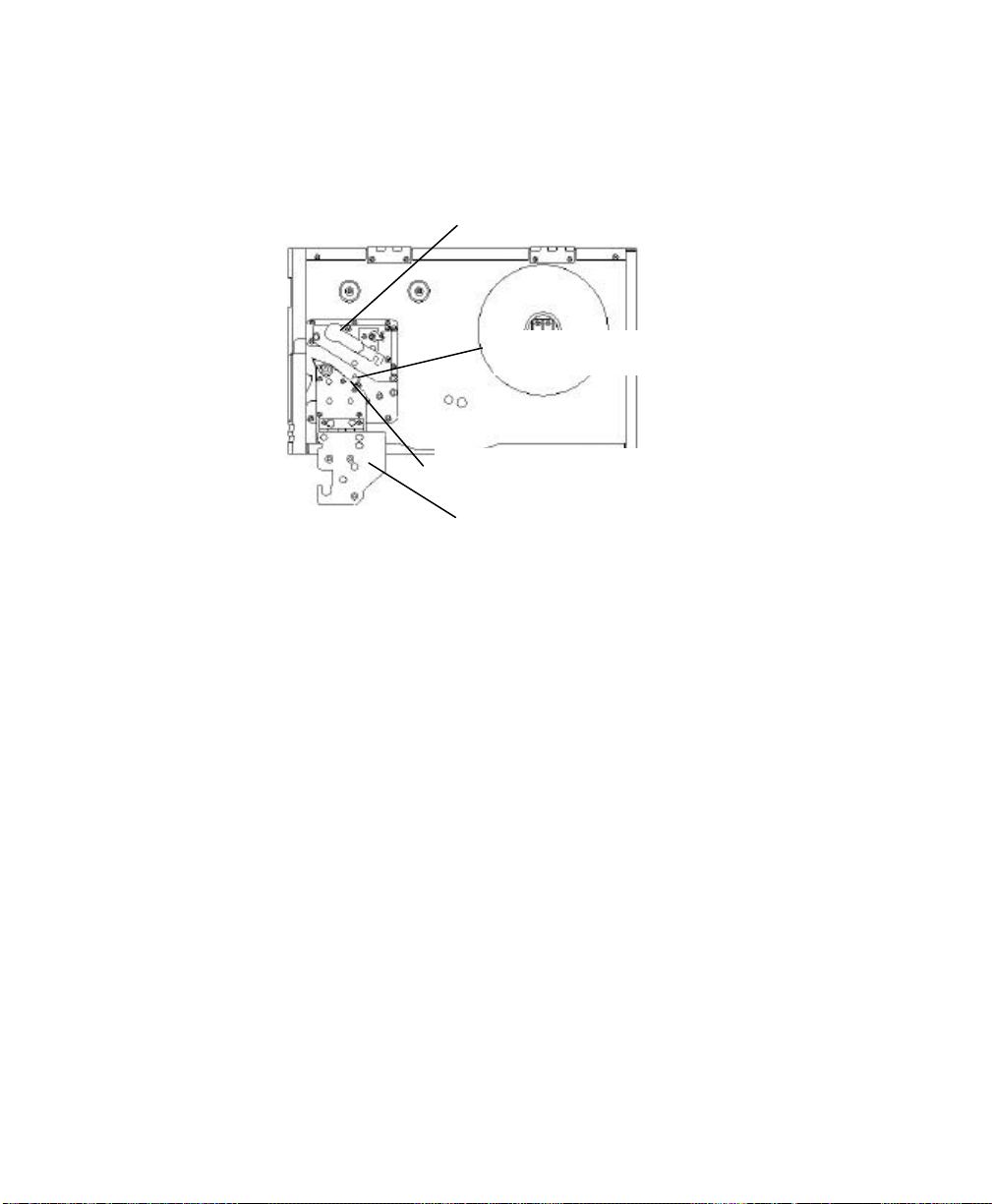
3. Rotate the Green Printhead latch counter-clockwise to open the printhead module.
4. Rotate the Side Access Door down to allow the ribbon to be loaded under the printhead
module. This will allow you to slide the ribbon under the printhead without having to
Printhead Latch
Upper Media Sensor Arm
Lower Media Sensor Arm
Side Access Door
thread it under the module.
Figure 10 - Printhead Latch and Side Access Cover
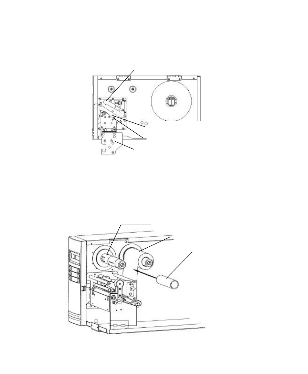
5. Unwrap the ribbon and place the Ribbon Supply Roll on the Ribbon Supply Spindle
located towards back of printer.
16 User's Guide
Take-up Spindle
Supply Roll and Supply Spindle
Empty Take-up core
Figure 11 - Ribbon Take-Up Core
6. Place the Ribbon Take-up core on the Ribbon Take-Up Spindle located towards the
front of the printer.
7. Slide both cores completely towards the center of the printer.
8. Route the ribbon under the print mechanism.
9. Important: Route ribbon under and around back of Ribbon Take-Up Core before
attaching using tape or adhesive leader.
10. Tighten ribbon by manually rotating the Take-up Core counter-clockwise.
Ribbon Take-Up Roll
Ribbon Take-Up Spindle
Front of Printer
Ribbon Supply Roll
Ribbon Supply Spindle
Figure 12 - Ribbon Routing
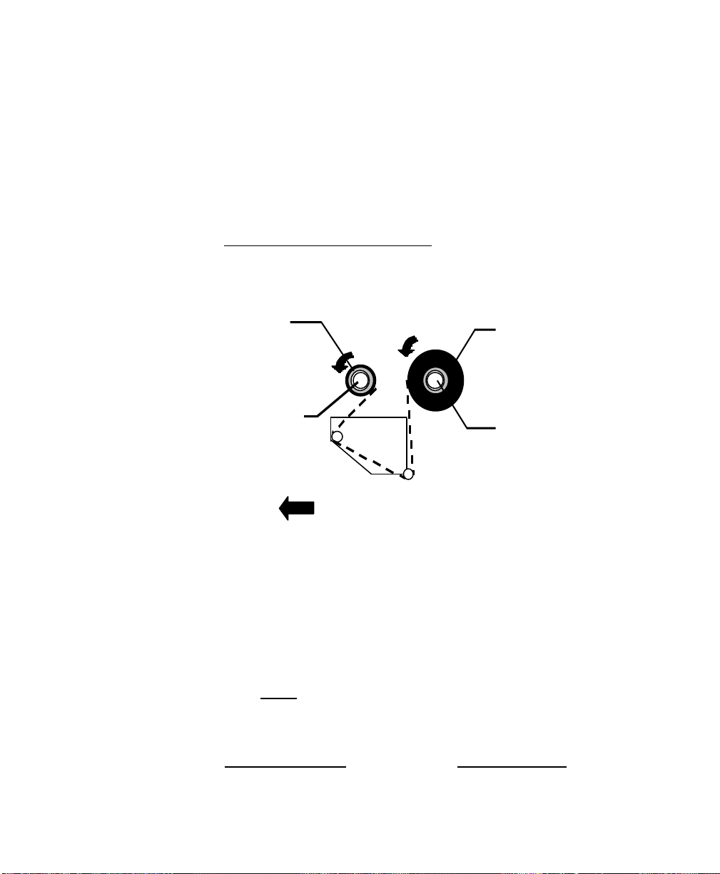
11. Important: To ensure proper ribbon operation complete the following checklist:
q Ribbon is wound ink in and feeding off the top of the Ribbon Supply Roll.
q Ribbon is re-wound on Take Up Roll from the bottom.
q Ribbon is routed above the Upper Media Sensor Arm. Only the media should
be below this arm.
q When properly loaded both the Ribbon Supply and Ribbon Take-Up Rolls will
be rotating counterclockwise as shown on the Ribbon Routing picture.
User's Guide 17

12. Verify if the printer is set for Thermal Transfer Mode:
a. To verify the FM4402 printer print a self-test. If the printer is not set for
Thermal Transfer mode, it can be set by using the Windows drivers, Utility
Software, or sending the appropriate printer commands via the host.
b. To verify the FM4602 and FM4603 printers are set to Thermal Transfer
mode, switch 1 (on the back of the printer) is set to the off position.
18 User's Guide
Loading Media
1. Fully open Media Access Cover.
2. Open the Front Access Door by rotating down.
Media Access Cover
Media Supply Guide
Media Supply Spindle
Front Access Door
Figure 13 - Open Media Access Cover
User's Guide 19
3. Rotate the green Printhead Latch counterclockwise to open the printhead.
4. Rotate the Side Access Door down to allow the media to be loaded under the printhead
module.
Printhead Latch
Upper Media Sensor Arm
Lower Media Sensor Arm
Side Access Door
Figure 14 - Printhead Latch and Side Access Cover
5. Slide the Media Supply Guide to the full widest position.
6. Ensure the media is face out with the labels feeding from the top of the roll. If not obtain
correctly wound media from your supplier
7. Place the media roll on the Media Supply Spindle.
8. Slide the roll fully towards the center of the printer.
9. Slide the Media Supply Guide towards the center of the printer until it is snug against
the media.
20 User's Guide
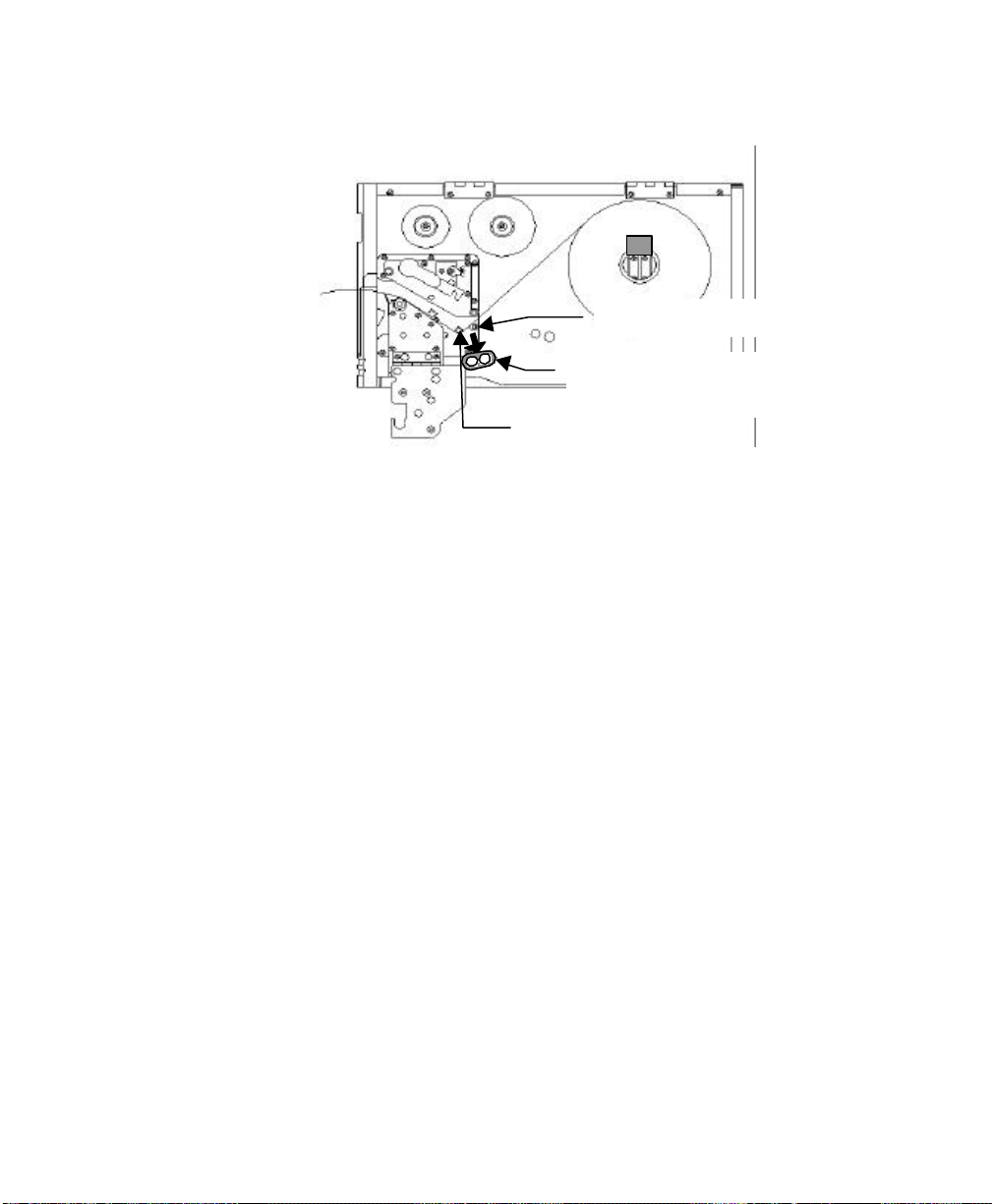
10. Slide the green Outside Media Guide off the Front and Back Media Rails by pulling
straight out.
Back Media Rail
Outside Media Guide
Front Media Rail
Figure 15 - Outside Media Guide
11. Thread the media over the Back Media Rail and under the Front Media Rail.
12. Continue feeding the media through the black Upper and Lower Media Sensor Arms
located under the print module.
13. Place the green Outside Media Guide (smooth side in) back onto the Front and Back
Media Rails.
14. Slide the Outside Media Guide towards the center of the printer until it just touches but
does not buckle the media.
User's Guide 21
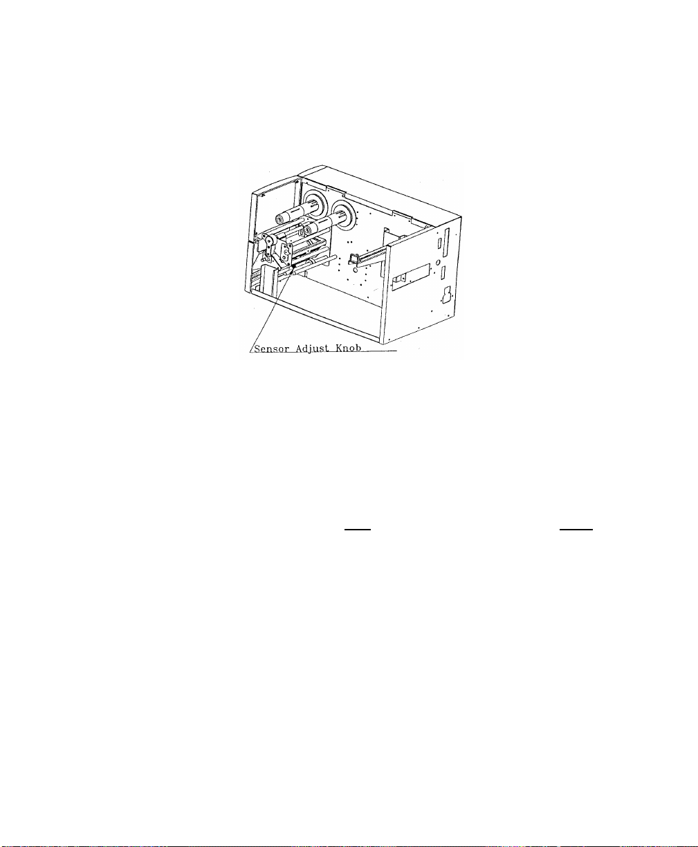
15. Grasping the Sensor Adjust Knob and sliding in or out as needed can move the Media
Sensor. This is required only if the sensor must be moved to a specific location on the
label to detect a notch (hole) or gap.
Figure 16 - Media Sensor Adjust Knob
16. Important: To ensure proper media feeding and sensor operation, complete the following
checklist:
q Media is wound Face Out (print side out) and feeding off the top of the roll.
q Media is routed exactly as shown over the Back Media Rail and under the
Front Media Rail.
q Media is routed between the Upper and Lower Media Sensor Arms located
under print module.
q The green Outside Media Guide has been re-installed.
q If required, the media sensor is adjusted directly over the notch (hole) or gap.
22 User's Guide
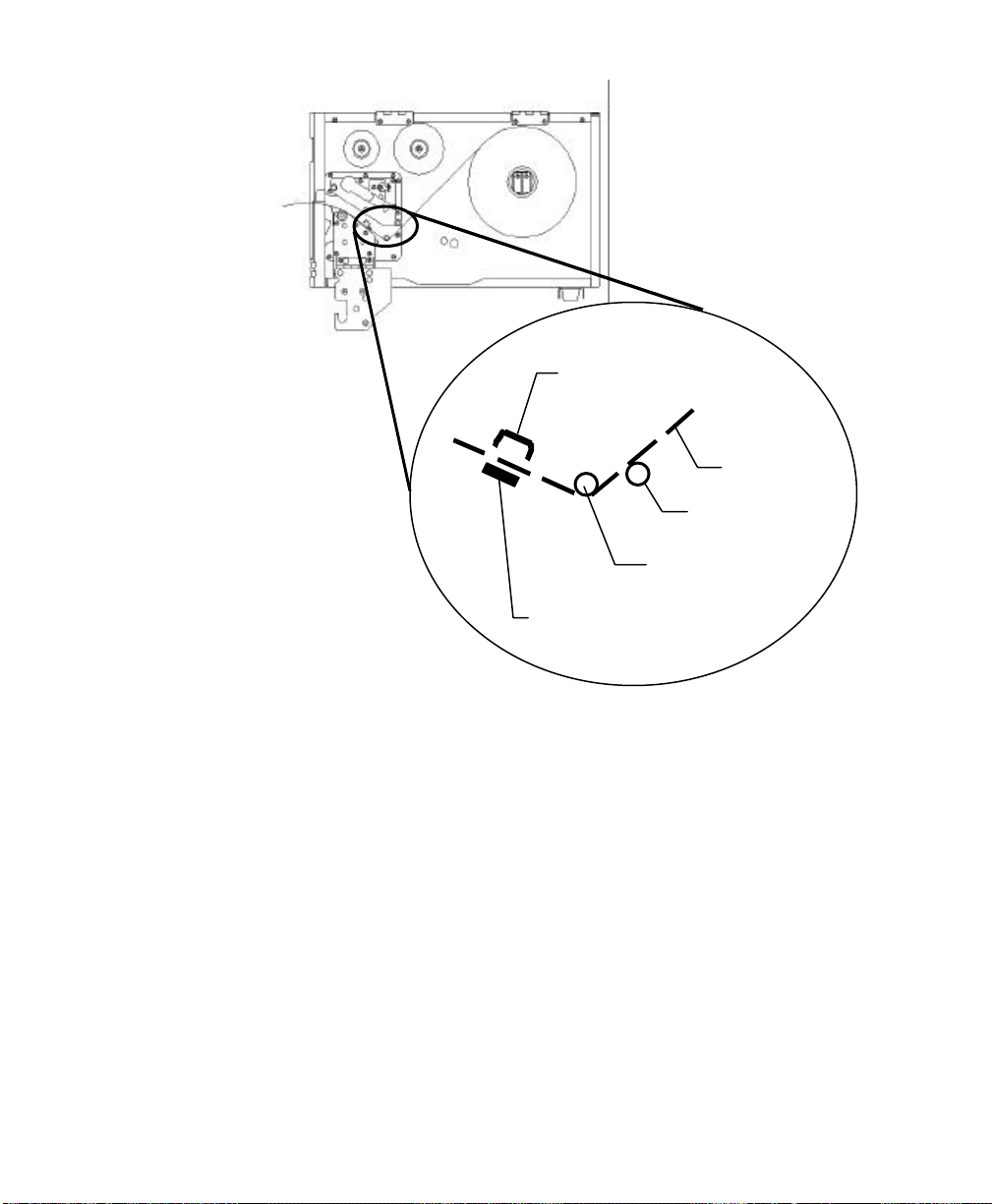
Upper Media Sensor Arm
Media
Back Media Rail
Front Media Rail
Lower Media Sensor Arm
Figure 17 - Media Routing
17. Rotate the Side Access Door up to close.
18. Rotate the green Print Head Latch clockwise fully to lock the printhead and Side
Access Door shut.
User's Guide 23
Changing Position of the Media Supply Spindle
The printer can store under the Media Access Cover an 8-inch outer diameter media roll that
is wound on either 1.5 inch or 3 inch inner cores. When the Media Access Cover is closed
touching on either the Media Cover or the bottom of the printer could cause unnecessary drag
on the form. The printer's Media Supply Spindle can be moved to accommodate these
issues.
To change the position of the Media Spindle:
1. Turn off the printer.
2. Remove the media from the Media Spindle.
3. Using a Phillips Screwdriver remove the 4 screws holding the Media Spindle to the center
of the printer.
4. Slide the Media Spindle to the appropriate position.
1.5 inch inner core: Media Spindle needs to be in the Lower position.
3-inch inner core: Media Spindle needs to be in the Upper Position.
5. Using a Phillips Screwdriver, install the 4 removed screws.
6. Reload the Media into the printer.
Upper Position
24 User's Guide
Lower Position
Figure 18 - Media Spindle Location

Calibrating Media Sensors
Important: The first time media is installed, the Media Sensors must be calibrated.
After the first calibration no further calibration is required unless the media type
(length, color, backing material, etc.) is changed or irregular feeding occurs.
1. Ensure the printer is powered off.
2. Verify that the media is properly loaded and routed as detailed in Loading Media Section.
3. While pressing and holding the PAUSE/CALIBR. button, power on the printer.
4. Release the PAUSE/CALIBR. button when:
a. FM4402: The printer begins feeding labels.
b. FM4602 and FM4603: The message “CALIBRATION …” is displayed on
the LCD.
5. Approximately 12 inches of media will be fed.
6. When feeding stops and the READY and MEDIA indicators stop blinking and remain
illuminated, the printer has completed the Label Sensor Calibration procedure.
On the models with a LCD, the printer will display 'READY'.
7. When the printer completes the Label Sensor Calibration procedure it will save the related
parameters (reflection characteristics, label length, etc.) to EEPROM.
Caution: Running labels that are less than 1.5 inches in length without
the correct calibration can result in loss of gap detection.
User's Guide 25

Performing the Self Test
1. Power off the printer.
2. Make sure that 4 inch wide media is installed. The Self-test will print the maximum width
of the installed label.
3. Press and hold the FEED/Config button.
4. Power on the printer.
5. Release the FEED/Config button when:
a. FM 4402: The printer begins feeding labels.
b. FM 4602 and FM 4603: The message “SELF TESTING…” is displayed on
the LCD.
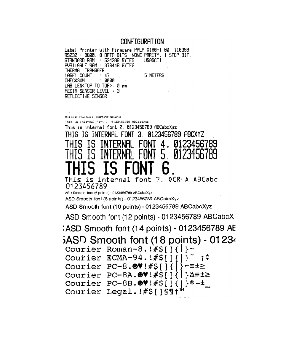
6. The following the occur depending upon the emulation installed into the printer:
PPLA emulation: The printer will print a configuration page then feed to the
first print position on the next label.
PPLB emulation: The printer will print a configuration page, feeds one line and
then enter into its Hexadecimal print mode. To exit the
Hexadecimal mode press the CANCEL/Reset button then
press the FEED/Config button to go to the first print position
on the next label.
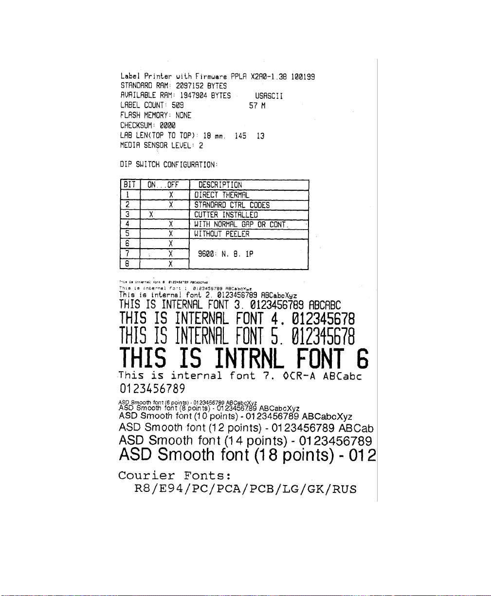
7. The following information will be printed on this report.
- Font list
- DIP switch settings (FM4602 and FM4603 only)
- Hardware configuration and status
- Label parameters
- Firmware version
Note: The following figures are examples of self-tests run on FM4402, and
FM4602/4603 with both PPLA and PPLB emulation's installed. The feature
setting on your printer may be different depending upon options selected.
Note: Print samples printed on the FM4602 and FM4603 are similar.
26 User's Guide
Self Test Pattern for FM4602/FM4603 PPLA
Figure 19 - Self Test FM4602/FM4603 PPLA
User's Guide 27

Self Test Pattern for FM4602/FM4603 PPLB
28 User's Guide
Figure 20 - Self Test FM6402/FM4603 PPLB
Self Test Pattern for FM4402 PPLA
Figure 21 - Self Test FM4402 PPLA
User's Guide 29
 Loading...