

AMT Datasouth documax 3300 User Manual

DOCUMAX 3300 SERIES
User’s Guide
Part No. 104431 Rev. G

Documax 3300 Series
Impact Printer
User’s Guide
Installation and Start Up
Keypad Configuration
Forms Handling
Features and Profiles
Troubleshooting and Maintenance
Specifications
Default Tables
System Administration Features
ASCII Conversion Charts
ASCII Characters Sets
Escape Sequence Quick Reference
DGCL Emulation
Document No. 104431 Revision G
AMT Datasouth Corp.
www.amtdatasouth.com

User’s Guide
Preface
Thank you for selecting the Documax printer. There are four standard models available.
Some sections of this manual are not applicable to all models. The models are:
• Single Tractor V-Throat
• Single Tractor with Top Pinch Rollers
• Dual Tractor with Top Pinch Rollers
• Dual Path, Tractor and Friction Feed (for Cut Sheet) with Top Pinch Rollers
Some of the procedures in this guide contain special notices that highlight important
information:
NOTES Indicate information that you should know to help your printer run
properly and efficiently.
CAUTIONS Indicate guidelines that, if not followed, can cause damage to
equipment.
WARNINGS Indicate a situation where there may be a danger to yourself.
The use of the terms right and left assume that you are looking at the front of the printer.
Preface 1

User’s Guide
Compliance
This device complies with part 15 of the FCC rules. Operation is subject to the following two
conditions:
1. This device may not cause harmful interference, and
2. This device must accept any interference received, including interference that may
cause undesired operation.
WARNING
CHANGES OR MODIFICATIONS TO
THIS UNIT NOT EXPRESSLY APPROVED
BY THE PARTY RESPONSIBLE FOR
COMPLIANCE COULD VOID THE
USER'S AUTHORITY TO OPERATE THE
EQUIPMENT.
2 Preface
NOTE
This equipment has been tested and found to comply with the
limits for a Class A digital device, pursuant to Part 15 of the
FCC Rules. These limits are designed to provide reasonable
protection against harmful interference when the equipment is
operated in a commercial environment. This equipment
generates, uses, and can radiate radio frequency energy and, if
not installed and used in accordance with the instructions, may
cause harmful interference to radio communications. Operation
of this equipment in a residential area is likely to cause harmful
interference, in which case the user will be required to correct
the interference at his own expense.

User’s Guide
NOTE
When connecting the printer to a host computer system,
always use shielded interface cables. The use of non-shielded
interface cables is a violation of the FCC emissions limits for
a Class A computing device. Do not leave unterminated
interface cables connected to the printer.
This digital apparatus does not exceed the Class A limits for radio noise emissions from
digital apparatus set out in the Radio Interference Regulations of the Canadian Department of
Communications.
Cet appareil numérique n'émet pas de bruits radioélectriques dépassant les limites applicables
aux appareils numériques de la classe A prescrites dans le Règlement sur le Brouillage
Radioélectrique édicté par le Ministére des Communications canadien.
Ob gesetzliche Bestimmungen eingehatten werden, hängt von
der Anwendung geschirmter Kabel ab. Der Anwender ist für die
Anschaffung der passenden Kabel selbst verantwortlich.
DIESES GERÄT WURDE IM HINBLICK AUF DIE EINHALTUNG DER
FUNKENTSTÖRBESTIMMUNGEN SOWOHL ALS EINZELGERÄT ALS AUCH IM
SYSTEM (ZUR SIMULATION NORMALER EINSATZBEDINGUNGEN) ÜBERPRÜFF.
DENNOCH IST ES MÖGLICH, DAß DIESEN FUNKENTSTÖRBESTIMMUNGEN
UNTER GEWISSEN UNVORTEIILHAFFEN BEDINGUNGEN IN SYSTEMEN NICHT
ENTSPROCHEN WIRD. DER ANWENDER IST SELBST FÜR DIE EINHALTUNG DER
GESETZLICHEN BESTIMMUNGEN BEIM BETRIEB SEINER ANLAGE
VERANTWORTLICH.
Preface 3

User’s Guide
BESCHEINIOUNG DES HERSTELLERS/IMPORTEURS
Hiermit wird bescheinigt, da ß der/die/das
Documax Model A3300
(Gerdt, Typ, Bezeichnung)
in Übereinstimmung mit den Bestimmungen der Vfg 1046
(DIN-DVE-Norm bzw, EN-Norm bzw, BMPT-AmstblVfg 242/1991, 46/1992) funkentstört ist.
Dem Bundesamt für Zulassungen in der Telekommunikation wurde das Inverkehrbringen
dieses Gerätes angezeigt und die Berechtigung zur Überprufung der Serie auf die Einhaltung
der Bestimmungen eingeräumt.
AMT Datasouth Corporation
(Name and Anschrift des Herstellers/Importeurs)
Diese Anzeige kann bei Geräten, die der EN 55014 bzw.
55015 entsprechen, entfallen
WARNING
Any alteration or modification to this equipment may cause non-compliance to:
WARNUNG
Jede Abdnderung oder Modifizierung dieses Gerdts kann eine Zuwiderhandlung gegen
folgende Bestimmungen darstellen:
ADVERTENCIA
Cualquier alteración o modificación de este equipo podría resultar en la infracción de:
ATTENTION
Tout changement ou modification apporté à cet équipement peut entraîner sa non conformité
au:
UL Safety Standard 1950
CSA Safety Standard C22.2 No. 950
FCC Regulations for Class A Computing Devices
VDE EMI Regulations Vfg 1046, Class A (GS marked units only)
EN50082-1 Class A Limits
EN60950
4 Preface

User’s Guide
CAUTION
The printer must have the correct line fuse installed for the selected input voltage.
VORSICHT
Im Drucker muß eine, der gewählten Eingangsspannung entsprechende Sicherung installiert
sein.
PRECAUCION
El fusible instalado en la línea de la impresora debe ser el apropriado para la tensíon de
entrada.
ADVERTISSEMENT
L’imprimante doit être munie d’un fusible adapté au voltage d’entrée choisi.
***************************************************************************
WARNING
The operator must disconnect the printer from the A.C. power supply before performing any
corrective action procedure that requires reaching into the printer.
WARNUNG
Die Stromzufuhr zum Drucker muß unterbrochen werden, bevor irgendwelche korrektiven
MaBnahman im Inneren des Geräts vorgenommen werden.
ADVENTERCIA
El usuario debe desconectar la impresora de la corriente altema AC antes de proceder con
cualquier arregio que requiera meter la mano dentro de la impresora.
ATTENTION
L’ opérateur doit débrancher l'imprimante de la source d'alimentation C.A avant de réaliser
toute procédure de correction manuelle dans l'imprimante.
Preface 5

User’s Guide
WARNING
Changes or modifications to this unit not expressly approved by the party responsible for
compliance could void the user's authority to operate the equipment.
WARNUNG
Abänderungen oder Modifizierungen dieses Geräts dürfen nur mit ausdrücklicher
Genehmigung der für die Zulassung verantwortlichen Stelle vorgenommen werden. Verstö ße
dagegen könnten den Widerruf der Zulassung des Geräts zur Folge haben.
ADVERTENCIA
Los cambios o modificaciones llievados a cabo en esta unidad, no aprobados explicitamente
por la parte responsable de cumplir con el regiamento, podrían invalidar la autoridad del
usuario para utilizar el equipo.
ATTENTION
Les changements ou modifications apportés cette unité non expressément approuvés par la
parte responsable de la conformité peuvent annuler I'autorité de l' utilisateur à operér 1'
équipement.
***************************************************************************
WARNING
Connect 115v (230v) units to 115v (230v) outlets only!
WARNUNG
115v (230v)-Geräte nur an 115v (230v)-Steckdosen anschließen!
ADVERTENCIA
iConecte unidades de 115v (230v) unicamente a tomas de 115v (230v)!
ATTENTION
Brancher les unités 115v (230v) uniquement sur des prises 115v (230v)!
6 Preface

User’s Guide
WARNING
The printhead gets hot during use. Wait until the printhead is cool before handling the
printhead.
WARNUNG
Der Druckkopf erhitzt sich, während das Gerät in Betrieb ist. Bevor Arbeiten am Druckkopf
durchgeführt werden, warten, bis dieser abgekühlt ist.
ADVERTENCIA
La cabeza impresora se recalienta con el uso. Esperar hasta que se enfríe antes de tocarta.
ATTENTION
La tête d' impression chauffe pendant l' usage. Attendre que la tête d'impression soit froide
avant de la manipuler.
***************************************************************************
WARNING
Connecting this equipment to an ungrounded power receptacle can result in the risk of
electrical shock.
WARNUNG
Dieses Gerät darf keinesfalls an eine ungeerdete Steckdose angeschlossen werden. Es besteht
Elektroschockgefahr.
ADVERTENCIA
El enchufar este equipo a una toma de corriente no conectada a tierra podría resultar en riesgo
de una descarga eléctrica.
ATTENTION
Brancher cet équipement á une prise non reliée à la terre peut provoquer une électrocution.
Preface 7

User’s Guide
WARNING
Make certain the printer is disconnected from the A.C. power supply before reaching into the
printer to perform any cleaning or maintenance task.
WARNUNG
Die Stromversorgung des Druckers muß unterbrochen sein, ebe irgendwelche Reinigungsoder Wartungsarbeiten vorgenommen werden.
ADVERTENCIA
Asegúrese de que la impresora esta desconectada de la corriente altema AC antes de
introducer la mano en su interior para cualquier labor de limpieza o mantenimiento.
ATTENTION
S' assurer que l' imprimante soit débranchée de la source d'alimentation C.A avant de réaliser
des tâches de nettoyage ou d'entretien manuelles.
***************************************************************************
8 Preface
SILICON SOFTWARE
1989 Ready Systems Corp. All rights reserved. Unpublished-rights
reserved under the copyright laws of the United States.
RESTRICTED RIGHTS LEGEND
Use, duplication or disclosure by the Government is subject to
restrictions as set forth in subparagraph (c)(1)(i) of the Rights in
Technical Data & Computer Software clause at DFARS
252.227-7013. READY SYSTEMS, 470 POTRERO AVENUE
SUNNYDALE, CA 94086

User’s Guide
Table of Contents
Title Page
Chapter 1. Installation and Start Up
1.1 Introduction........................................................................................................1-1
1.2 Quick Start Up Procedure ...................................................................................1-2
1.3 Unpack the Printer..............................................................................................1-4
1.4 Choosing a Place for the Printer...........................................................................1-5
1.5 Printer Parts.......................................................................................................1-6
1.6 Install the Power Cord...................................................................................... 1-11
1.7 Install the Ribbon Cartridge ...............................................................................1-13
1.8 Printer Self Test ............................................................................................... 1-20
1.9 Interfacing........................................................................................................ 1-22
1.10 RS-232 and RS-422 Serial Interface Configuration ............................................ 1-24
Chapter 2. Keypad Configuration
2.1 Keypad Configuration.........................................................................................2-1
2.2 Ready LED ........................................................................................................2-2
2.3 On/Off Line Key Function...................................................................................2-3
2.4 LCD Display ......................................................................................................2-6
Chapter 3. Forms Handling
3.1 Recommended Types and Sizes ...........................................................................3-1
3.2 Paper Paths........................................................................................................3-2
3.3 Load Forms........................................................................................................3-3
3.4 Top of Form Adjustment................................................................................... 3-13
(Adjusting First Printline Location)................................................................... 3-13
3.5 Tear Off Adjustment......................................................................................... 3-15
3.6 Form Thickness Adjustment.............................................................................. 3-18
3.7 Heavy Forms Adjustment ..................................................................................3-21
3.8 Changing From Main Paper Path to Alternate Path............................................. 3-22
3.9 Changing From Alternate Paper Path to Main Paper Path....................................3-24
3.10 Paper Out Condition......................................................................................... 3-25
3.11 Automatically Changing Paper Paths on Paper Out............................................3-26
3.12 Selecting Paper Paths Using the Profile Key...................................................... 3-27
3.13 Selecting Paper Paths From the Host Computer Using DPCL Command............. 3-29
Table of Contents i

User’s Guide
Chapter 4. Features and Profiles
4.1 Features.............................................................................................................4-1
4.2 Profiles ..............................................................................................................4-2
4.3 Setup Mode Key Functions..................................................................................4-4
4.4 LCD Display ......................................................................................................4-6
4.5 Profile Feature Listing.........................................................................................4-7
4.6 Changing Features in a Profile .............................................................................4-8
4.7 User Programmable Features............................................................................. 4-11
Chapter 5. Troubleshooting and Maintenance
5.1 Scheduled Maintenance ......................................................................................5-1
5.2 Error Message....................................................................................................5-3
5.3 Printer Diagnostics .............................................................................................5-8
5.4 Troubleshooting................................................................................................ 5-16
5.5 Troubleshooting Table ...................................................................................... 5-17
ii Table of Contents

User’s Guide
Title Page
Appendix A. Printer Specifications
A.1 Printer Characteristics .......................................................................................A-1
A.2 Emulations .......................................................................................................A-1
A.3 Font Specifications ...........................................................................................A-2
A.4 Paper Feed Specifications ..................................................................................A-4
A.5 Forms Mode Change .........................................................................................A-5
A.6 Communications Interface ................................................................................A-5
A.7 Operator Panel Functional Description...............................................................A-6
A.8 Ribbon Cartridge/Drive.....................................................................................A-6
A.9 Physical...........................................................................................................A-6
A.10 Electrical..........................................................................................................A-7
A.11 Shock and Vibration..........................................................................................A-7
A.12 Environmental..................................................................................................A-7
A.13 Compliances ....................................................................................................A-8
Appendix B. Interface Specifications
B.1 Parallel Interface.............................................................................................. B-1
B.2 Parallel Interface Enable/Disable ..................................................................... B-6
B.3 RS-232 Serial Interface..................................................................................... B-7
B.4 Serial Inte rface Selection................................................................................. B-10
Appendix C. Default Tables
C.1 Menu 1: Page Format........................................................................................ C-1
C.2 Menu 2: Forms Control..................................................................................... C-2
C.3 Menu 3: Personality.......................................................................................... C-2
C.4 Menu 4: Printer Control..................................................................................... C-3
C.5 Menu 5: Serial Interface.................................................................................... C-4
C.6 Menu 6: Parallel Interface .................................................................................C-4
C.7 Menu 7: Profile Control..................................................................................... C-5
C.8 Menu 8: Form Thickness Control....................................................................... C-5
C.9 Menu 9: Diagnostics......................................................................................... C-6
C.10 Menu 10 System Control................................................................................... C-7
Table of Contents iii

User’s Guide
Title Page
Appendix D. System Administration Features
D.1 Features Available In System Control Menu .......................................................D-1
D.2 Menu 10: System Control.................................................................................D-2
D.3 Key Functions That Can Be Locked...................................................................D-5
Appendix E. ASCII Conversion Chart
Appendix F. ASCII Character Sets
F.1 ASCII Character Sets........................................................................................ F-1
F.2 7 Bit ASCII Character Set................................................................................. F-2
F.3 IBM Code Page 437 Symbol Set........................................................................ F-4
F.4 IBM Code Page 850 Symbol Set........................................................................ F-6
F.5 Epson Italic Symbol Set .................................................................................... F-8
F.6 Epson Gr aphics Symbol Set .............................................................................F-10
F.7 Epson Italic Graphics Symbol Set .....................................................................F-12
F.8 DEC Supplemental Symbol Set........................................................................F-14
F.9 Nationality Overlay Character Set....................................................................F-16
Appendix G. Escape Sequence Quick Reference
G.1 Epson FX......................................................................................................... G-1
G.2 IBM Proprinter................................................................................................. G-5
G.3 DEC LA-120 ....................................................................................................G-8
G.4 TI-885 (optional) ............................................................................................G-12
G.5 DS-180 ..........................................................................................................G-15
G.6 DPCL Command Sequence Summary..............................................................G-19
Appendix H. DGCL
H.1 Datasouth Graphics Command Language ...........................................................H-1
H.2 Transparency Mode..........................................................................................H-3
H.3 Task Mode.......................................................................................................H-7
H.4 Sample Program for AIAG Label..................................................................... H-10
iv Table of Contents

User’s Guide
1. Installation and Start Up
1.1 Introduction
This dot matrix impact printer provides high-speed performance, plus a rugged, round-theclock duty cycle, and flexibility to handle a number of printing applications.
Feature Highlights
• Straight through pin feed paper path for optimum forms handling.
• Nine wire ballistic printhead and flat metal print platen to assure legibility on every copy.
• Demand document printing.
• Automatic Form Thickness adjustment.
• Forms parking and reloading at the touch of a key.
• Four user-defined profiles for quick forms set up.
• Paper path selection by profile.
• Emulations: Epson FX, DEC LA 120, IBM Graphics, IBM Proprinter XL
• Options:
a. Second pin feed paper path
b. Cut sheet paper path
c. IBM Coax, IBM Twinax interfaces
d. Quiet cover set
e. Barcodes
f. Network Interface
Keypad Configuration 1-1

User’s Guide
1.2 Quick Start Up Procedure
The following is an abbreviated installation and start up procedure provided for users who are
already familiar with printer products. If you are not experienced with printers, follow all the
instructions in Chapter 1 for setting up the printer.
1. Place the printer on a suitable stand or countertop.
2. Install ribbon cartridge and power cord.
WARNING
CONNECT 115V UNITS TO 115V
OUTLETS ONLY! PRINTER DAMAGE
WILL RESULT!
3. Turn printer on
4. Position left tractor with ‘Alignment’ mark on printer. Position front paper guides and
rear paper supports equally across the width of the form. Load 8 ½” paper into
tractors. (For cut sheet forms, set the left cut sheet guide to “0” and insert 8 ½” paper).
5. Press the Load Key (unnecessary for cut sheet path).
6. Open Keypad Door to enter Setup Mode .
7. Use the Quick Access Key, the Value ▲▼ keys, and the Enter Key to set margins.
8. Close the Keypad Door.
9. Press the Profile Key to save settings.
10. Open Keypad Door.
1-2 Keypad Configuration

User’s Guide
CAUTION
IMPROPER MARGIN SETTING CAN
LEAD TO PRINTHEAD DAMAGE! DO
NOT PRINT OFF THE EDGE OF THE
FORM.
11. Press the Feature ▲ Key. LCD should display “Self Test”.
12. Press the Enter Key.
When the Enter Key is pressed, the self test will begin printing. The self test may be stopped
by closing the Keypad Door or pressing the Enter Key.
Keypad Configuration 1-3

User’s Guide
1.3 Unpack the Printer
Remove the following from the shipping carton:
• Dot Matrix Printer
• Ribbon Cartridge
• Power Cord
• Accessory Kit: User's Manual
Warranty Card
If any items are missing, please contact your distributor. Save the shipping carton and all
packing materials. These items will be needed in the event the printer must be shipped.
CAUTION
SHIPPING THE PRINTER IN ANY
CONTAINER OTHER THAN ITS
ORIGINAL PACKAGING MAY RESULT
IN SHIPPING DAMAGE AND MAY VOID
THE PRINTER WARRANTY.
1-4 Keypad Configuration

User’s Guide
1.4 Choosing a Place for the Printer
The printer weighs approximately 45 pounds. Its dimensions are:
• 17.0 inches (431 mm) wide x 15.7 inches (398 mm) deep x 12.3 (312 mm) inches high
(Dual tractor, top roller versions).
• 17.0 inches (431 mm) wide x 15.7 inches (398 mm) deep x 11.3 inches (287 mm) high
(Standard model).
• 17.0 inches (431 mm) wide x 16.7 inches (424 mm) deep x 12.3 inches (312 mm) high
(Cut Sheet model).
Location
1. To permit air flow and proper cooling, do not place anything closer than 2 inches
(50mm) to the printer.
2. Allow 6 inches to the right of the printer for access to the Form Thickness Adjustment
knob.
3. For continuous printing and accumulation of forms, allow sufficient room behind the
printer for cables and stacking forms.
4. Place the printer on a sturdy level surface and align lower front edge of printer with
table edge.
5. Locate the printer near a grounded power receptacle and use the power cord provided.
Do not use an extension cord to connect the printer.
6. Avoid the following:
• Direct sunlight or excessively illuminated areas
• Direct placement in front of air conditioning or heating vents
• Extreme high or low temperatures
• Exposure to excessive dirt or dust
• Exposure to vibration or mechanical shock
• Excessive humidity or condensation
Keypad Configuration 1-5
User’s Guide
1.5 Printer Parts
Four basic models of the printer are available:
• Standard straight tractor paper path with standard access cover.
• Straight tractor paper path with top roller set and sound reduction access cover.
• Dual tractor path (straight and 45 °) with top roller set and sound reduction access cover.
• Straight tractor path and cut sheet (Friction Feed) path with top roller set and sound
reduction access cover.
Use the following illustrations to locate the major printer parts for each model. The standard
model is used to illustrate most of the procedures in this manual.
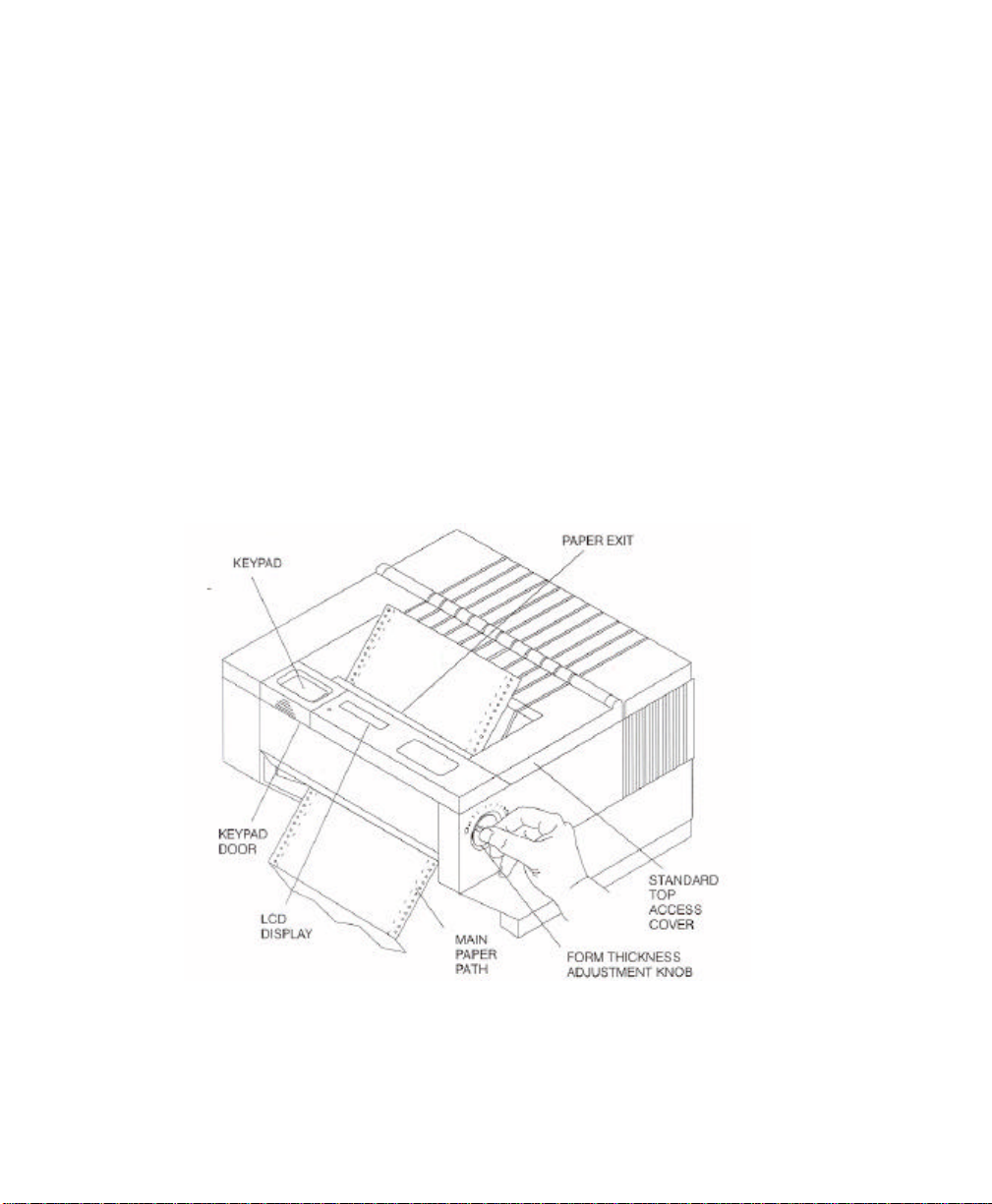
Figure 1-1: External Printer Parts (Standard Model) (Sheet 1 of 2)
1-6 Keypad Configuration
User’s Guide
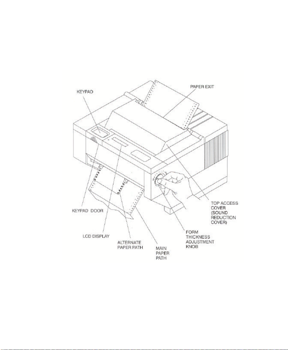
Figure 1-1: External Printer Parts (Dual Path and Sound Reduction Access Cover)
(Sheet 2 of 2)
Keypad Configuration 1-7
User’s Guide
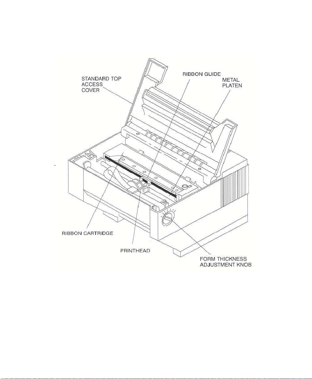
Figure 1-2: Internal Printer Parts (Standard Model) (Sheet 1 of 2)
1-8 Keypad Configuration
NOTE
Keypad assembly is not shown in order to
identify the printhead.
User’s Guide
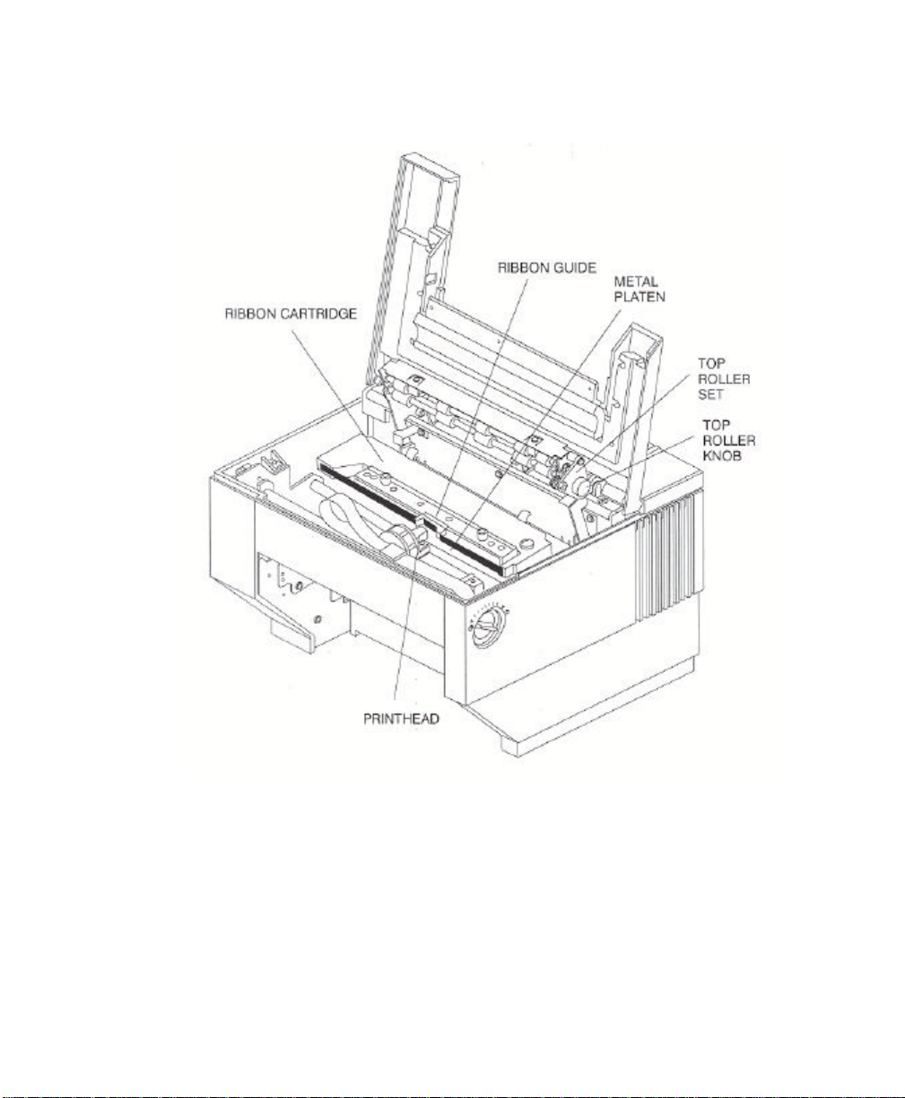
NOTE
Keypad assembly is not shown in order to
identify the printhead.
Figure 1-2: Internal Printer Parts (w/Top Roller Option) (Sheet 2 of 2)
Keypad Configuration 1-9
User’s Guide
1-10 Keypad Configuration
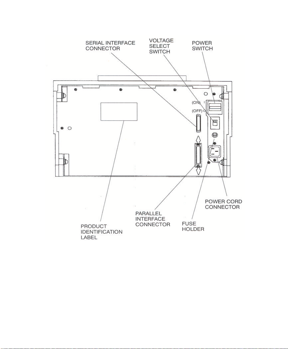
Figure 1-3: Back Printer Parts

User’s Guide
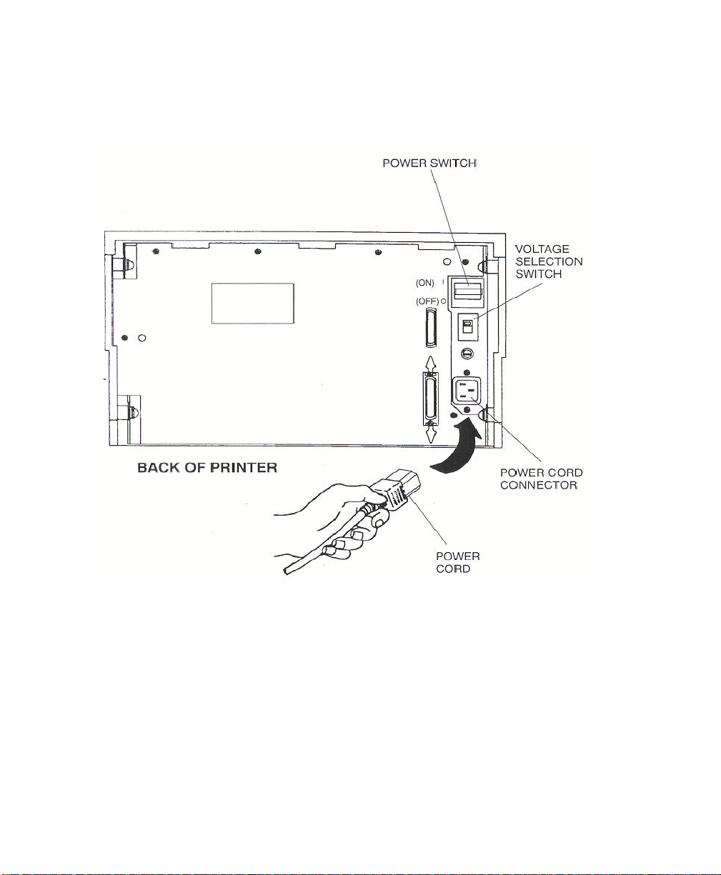
1.6 Install the Power Cord
1. Set the power switch to Off. (See Figure 1-4).
2. Install the power cord into the printer as shown in Figure 1-4.
3. Verify that voltage setting is correct for the application (115V-U.S.) (See Figure 1-4).
WARNING
CONNECTING THIS EQUIPMENT TO AN
UNGROUNDED POWER RECEPTACLE
CAN RESULT IN ELECTRICAL SHOCK.
4. Install the plug end of the power cord into a grounded AC outlet. The voltage of the
AC power receptacle must match the voltage rating on the power cord receptacle label.
A grounded outlet must be used. Plugging the printer into an ungrounded outlet may
result in increased radio frequency noise generation, erratic printer operation, or
electrical shock.
5. Set the power switch to ON. The alarm will sound 3 short tones and the printer will
display:
Paper Out: Main
Keypad Configuration 1-11
User’s Guide
1-12 Keypad Configuration
Figure 1-4: Install Power Cord

User’s Guide
NOTE
1.7 Install the Ribbon Cartridge
To prolong ribbon life, the printer is shipped without the cartridge installed. The following
procedure is written for both initial installation and ribbon replacement.
1. Press the On/Off Line key to display "off line" status.
If paper is loaded, press PARK key to park
the form in the tractors.
2. Open top access cover and lift roller assembly on models so equipped.
Keypad Configuration 1-13
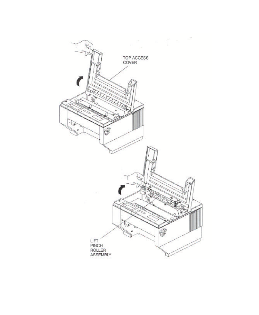
User’s Guide
Figure 1-5: Open Access Cover (Both Options)
1-14 Keypad Configuration

User’s Guide
NOTE
3. Check the Form Thickness Adjustment Knob to be sure that it is in the first position as
shown in Figure 1-6.
If replacing the ribbon, the Form Thickness
Adjustment Knob will automatically move
away from the form when the paper is parked
in the tractors.
Figure 1-6: Form Thickness Adjustment Knob
Keypad Configuration 1-15
User’s Guide
NOTE
Steps 4 and 5 are not required for initial
ribbon installation.
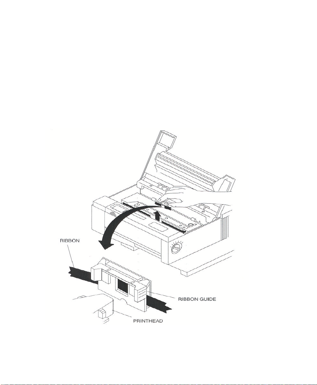
4. Remove the ribbon guide from printhead (lift up and rotate towards front).
5. Remove ribbon cartridge from printer.
Figure 1-7: Remove Ribbon Guide
6. Move the printhead to the center of the printer.
1-16 Keypad Configuration
 Loading...