

AMT Datasouth 7200 User Manual

7200
ATB Printer
User's Guide
Part No. 111017 Rev. D

Contents...
Introduction.............................................................. i
7200
Table of
1. Before Using the ATB Printer ......................... 1-1
1.1 Checking the Package ....................................................... 1-2
1.2 Names and Functions ........................................................ 1-3
2. Operation.......................................................... 2-1
2.1 Connecting the ATB Printer.............................................. 2-2
2.2 Turning the Power On and Off .......................................... 2-4
2.3 Loading the Documents .................................................... 2-5
2.4 Setting Documents in BIN 3 ............................................. 2-9
2.5 Loading Documents into the Inserter .............................. 2-13
2.6 Installing the Transfer Ribbon (TT Only) ....................... 2-14
2.7 Changing Transfer Ribbons (TT Only) ........................... 2-18
3. Daily Maintenance ........................................... 3-1
3.1 Cleaning the ATB Printer.................................................. 3-2
3.1.1 Cleaning the Printer Surface ................................. 3-2
4. Troubleshooting .............................................. 4-1
4.1 Paper Jam .......................................................................... 4-2
4.2 Error Messages ................................................................ 4-12
Appendix 1: Specifications ........................................ A-1
Appendix 2: Consumables ......................................... A-5
Operation Manual
3.1.2 Cleaning the Magnetic Head................................. 3-3
3.1.3 Cleaning the Thermal Head .................................. 3-5
3.1.4 Cleaning a Platen Roller ....................................... 3-6
3.1.5 Cleaning a Carrier Roller ...................................... 3-7
3.1.6 Removing Paper Dust ........................................... 3-9

7200
(Page is intentionally blank)
Operation Manual

7200
INTRODUCTION
NOTICE
This equipment has been tested and found to comply with the limits for a Class A digital device,
pursuant to Part 15 of the FCC Rules. These limits are designed to provide reasonable protection
against harmful interference when the equipment is operated in a commercial environment.
This equipment generates, uses and can radiate radio frequency energy and, if not installed and
used in accordance with the instruction manual, may cause harmful interference to radio
communications. Operation of this equipment in a residential area is likely to cause harmful
interference in which case the user will be required to correct the interference at his own expense.
FCC WARNING
Changes or modifications not expressly approved by the party responsible for compliance could
void the user's authority to operate the equipment.
Operation Manual
i
7200
Product Safety
This manual uses a variety of terms and symbols to ensure the safe operation of the product,
help prevent hazards to yourself and others, and help prevent property damage. The
following
describes terms, symbols, and meanings used in this manual. Before reading this manual,
please familiarize yourself with the terms and symbols below.
Terms
WARNING
CAUTION
Symbols
The triangle indicates the presence of danger. Specific details
of the danger are described in the triangle. (The symbol on the
right indicates danger of electric shock.)
This symbol indicates a prohibited action. Specific details of
the prohibition are described in or near the symbol. (The
symbol on the right indicates the item should not be
disassembled.)
This symbol indicates a mandatory action. Specific details of
the action are described in the symbol. (The symbol on the
right indicates that the power cable must be unplugged.)
Ignoring this cautionary note and handling the product
improperly may result in death or serious injury.
Ignoring this warning and handling the product improperly
may result in injury or physical property damage.
Operation Manualii
7200
Safety Considerations
READ THIS PAGE BEFORE INSTALLING OR USING THIS PRODUCT!
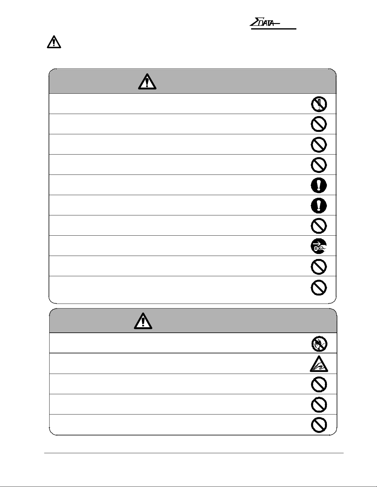
WARNING
n Do not remove the cover or attempt any repairs on this product. There is risk
of electric shock.
n Do not place heavy materials on the power cable. Do not bend or twist the power cable.
The cable may get damaged, causing fire or electric shock.
n Do not use damaged cables or broken connector or power plugs. There is risk
of fire or electric shock.
n Use only power voltages specified for this product. Improper voltages create a risk of
fire or electric shock.
n Securely plug the power cable into a power receptacle. Metal objects touching the
power plug may cause fire, electric shock, or equipment malfunction.
INTRODUCTION
n Hold the plug when unplugging the power cable. Do not pull on the power cable itself,
or the cable may become damaged and cause fire or electric shock.
n Be careful not to drop anything into any opening of the product. Never push anything
into the openings. There is risk of fire or electric shock.
n In the event of any abnormality (such as smoke or odors), unplug the power
cable immediately. There is risk of fire or electric shock.
n Do not install the product where water splashes are likely or in areas of high humidity.
There is risk of fire or electric shock.
n Do not place drink or liquid containers or small metal objects on the product. These
items may cause fire or electric shock if they spill or fall inside. Immediately unplug
the power cable if liquids or metal objects are spilled on the product.
CAUTION
n Do not use isopropyl alcohol around open flames or heat sources. Alcohol is highly
flammable and creates a risk of fire or explosion.
n Be careful when opening or closing covers. Do not take your hands off covers when opening
or closing them. Falling covers may cause injury.
n Be careful when opening, closing, or moving covers. Take care not to hit your face, head, or
hands with the open cover. You may be injured.
n Do not block the air ventilation holes of the product. Blocking the vents accumulates heat
inside the cabinet and can lead to product failure, heat, or fire damage.
n Do not install the product on an unstable or inclined surface. The product may fall and cause
damage or injury.
Operation Manual
iii

7200
Caution Label
This product comes with a caution label attached as described below.
Caution Label
CAUTION
Falling covers may
cause injury.
Do not take your
hands off covers
when opening and/
or closing them.
Operating Environment
Location
• Do not place the product in direct sunlight or near heating sources such as stoves or
heaters.
• Do not place the product in a dusty or humid environment.
• Do not place the product under strong shock or vibration.
• Do not place the product in a strong magnetic or radio field, or near a television set or
radio.
• Make sure that the vents are not blocked. Make sure that the installation location is well
ventilated and that air can freely circulate around the product.
• Do not place the product where contact with chemicals is likely.
Operation Manualiv
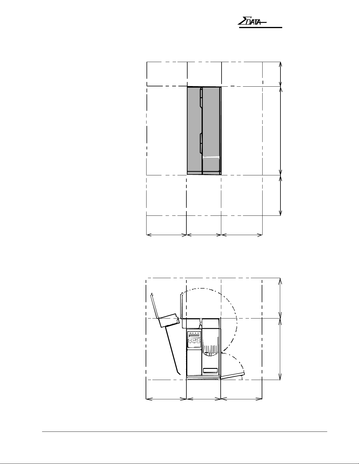
Space Required
Back
7200
INTRODUCTION
Left
9.8 in (250mm)
Front
8.3 in
(210mm)
Right
21.6 in (550mm)
9.8 in (250mm)
9.8 in (250mm)
Operation Manual
Top
Left
9.8 in (250mm) 9.8 in (250mm)
8.3 in
(210mm)
Right
15 in (380mm) 9.8 in (250mm) 5.9 in (150mm)
inches (millimeters)
v

7200
Dimensions and Weight
• 8.3 inches (210mm) W x 21.6 inches (550mm) D x 15.0 inches (380mm) H
• Less than 35.3 lb. (16 kg )
Temperature and Humidity
Make sure that the following temperature and humidity conditions are met :
• Ambient temperature: 41 to 104 degrees F (5 to 40 degrees C)
• Ambient humidity: 20% to 90% RH (relative humidity) — no condensation.
Notes on the Operating Environment
When installing the product where the ambient humidity is 30% or less, it is recommended that
you use a humidifier to raise the humidity to higher levels. Use an antistatic mat as necessary.
Power Connection
Power Line Conditions
Ensure that the power supply satisfies the following requirements:
• Voltage: 85 to 132 or 170 to 265 VAC (automatic voltage switching)
• Frequency: 47 to 63 Hz
• Power consumption: 250 VAC (Printing) or 80 VAC (Stand by)
If the power line is unstable, use a voltage regulator or similar device.
Connecting to Power
To connect the ATB printer to the power line, follow the instructions below:
• Plug the power cable of the printer in a dedicated wall receptacle. Do not plug any other
electric products into the same receptacle. If the printer shares a receptacle with an air
conditioner, copy machine, or shredder, faulty operation may result due to electric noise. If a
dedicated wall receptacle cannot be used, use a commercially-available noise filter or
transformer.
• Route the power cable such that people do not step on it. Do not place anything on the power
cable.
Important Note on the Side Cover
As a measure of safety, this ATB printer cannot be operated while the side cover is open.
Close the side cover and lock the cover with the key to print coupons.
Operation Manualvi
7200
INTRODUCTION
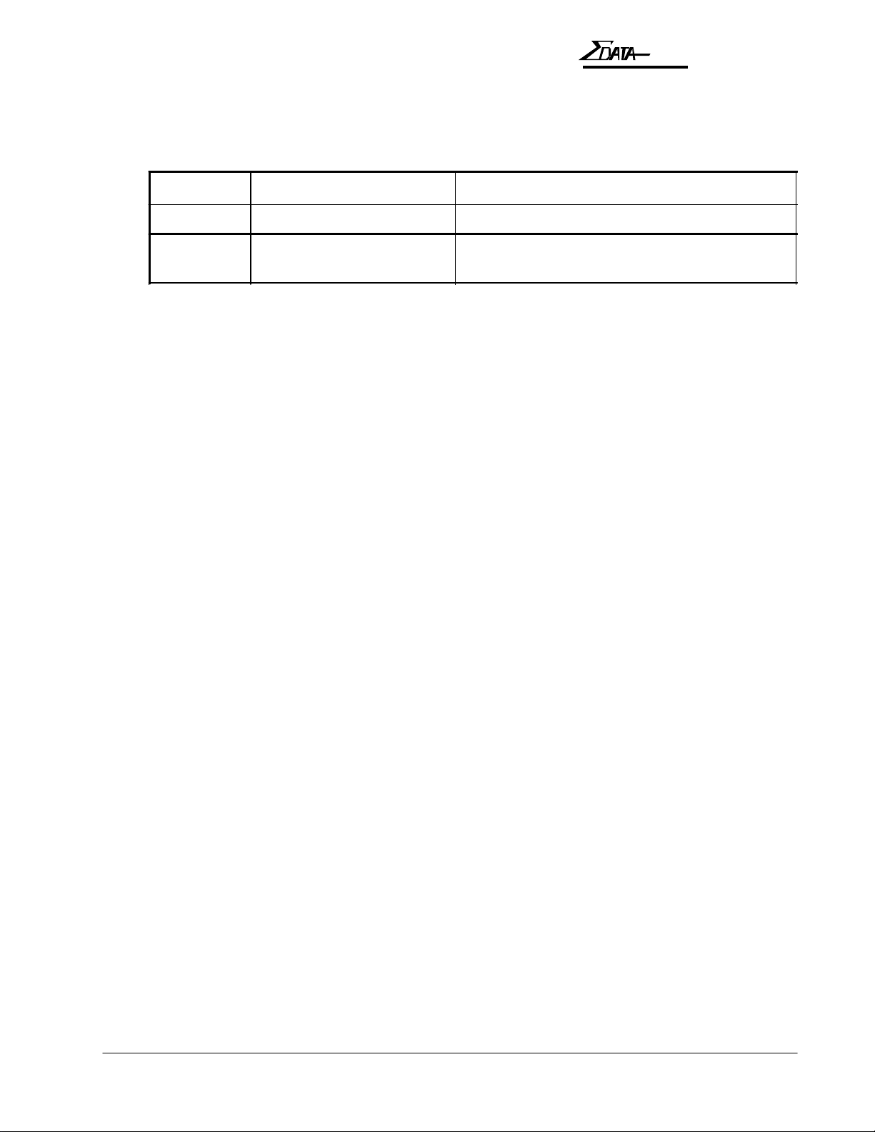
Available Types
The Sigma Data — 7200 ATB printer is classified into 2 types, i.e., Type B and Type D. Refer
to the printer types listed below when reading this manual.
Type Printing Method Number of Bins
Type B Direct thermal only Two internal bins and one external bin (BIN 3)
Type D Direct thermal or
thermal transfer
Two internal bins and one external bin (BIN 3)
Note:
Type B cannot be used for Thermal Transfer printing with a transfer ribbon.
Operation Manual
vii

7200
NOTES (page is intentionally blank)
Operation Manualviii

7200
BEFORE USING THE S7200
1. Before Using the ATB Printer
1-1Operation Manual

7200
1.1 Checking the Package
The ATB printer and accessories are packed in the same box. Carefully remove the printer and
accessories from the box and packing materials, then check that the package contains all of the
items needed for operation that are pictured below. The package also contains a warranty card
and may have other information sheets.
ATB Printer
AC Power Cable
Keys
Cleaning Kit
Operation Manual
1-2 Operation Manual

1.2 Names and Functions
This section explains the names and functions of each part.
1.2.1 Names of Parts
A — Operator panel
D — Output stacker
7200
BEFORE USING THE S7200
B — Cover lock
E — Feed knobs
N — BIN 3
M — Interface connector
(Host)
C — Inserter
O — Thermal
transfer take-up reel
F — BIN 1,
BIN 2, and
BIN 3 load
knobs
G — BIN 1
H — BIN 2
I — Thermal print head
P — Thermal transfer supply reel
J — Interface connector
(Downline)
HOST DOWNLINE
K — Power switch
L — Power connector
1-3Operation Manual
7200
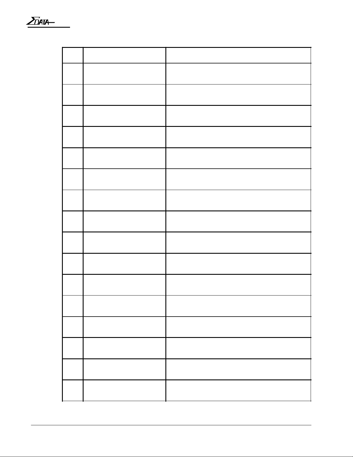
1.2.2 Functions
No. Names Functions
A Operator panel Houses the LEDs and keypad needed to operate
B Cover lock Locks the side cover. (Use the key to open the
C Inserter Used to insert single coupons (one at a time).
D Output stacker Receives ejected coupons, print-side up. (Has a
E Feed knobs Used to remove jammed coupons.
the ATB printer.
cover.)
capacity of 100 coupons.)
F BIN 1, BIN 2, and BIN 3
load knobs
G BIN 1 Used to hold coupons for printing. (BIN 1 has a
H BIN 2 Used to hold coupons for printing. (BIN 2 has a
I Thermal head Prints on the coupon.
J Interface connector
(downline)
K Power switch Turns the power on and off.
L Power connector Used to connect the power cable.
M Interface connector (Host) Used to connect the ATB printer to the terminal.
Used to load coupons into the feed rollers for
each bin.
capacity of 500 coupons.)
capacity of 500 coupons.)
Used to connect the printer to a downline printer
(reserved).
N BIN 3 Used to insert coupons. (BIN 3 has a capacity of
1000 coupons externally.)
O Thermal transfer take-up
reel
P Thermal transfer supply
reel
1-4 Operation Manual
Holds used ribbon after thermal transfer printing
(type D unit only).
Supplies ribbon for thermal transfer printing (type
D unit only).

1.2.3 Operator Panel
Operator Panel Layout
7200
BEFORE USING THE S7200
LEDs
LCD
16 columns by 2 rows
Keys
QUITQUIT
SET UPSET UP
èè
ERRORERROR
éé
CLEANINGCLEANING
êê
ONLINEONLINE DATADATA MODEMODE
ONLINEONLINE RESETRESET EJECTEJECT
ENTERENTER
TESTTEST
çç
LED Functions
LEDs indicate printer status by turning on, turning off, or blinking.
ONLINE
ON
— The ATB printer is online. The ATB printer can
receive and print data from the terminal. The printer is
set online when the power is turned on.
OFF
— The ATB printer is offline (i.e., Setup and Test
available).
— An ATB printer error or improper Host connection.
— The ATB printer is sending or receiving data to or from
DATA
Blinking
ON
the terminal, or is printing coupons.
ERROR
MODE
ON
ON
— An error or jam has occurred. (The buzzer sounds.)
— The ATB printer is in TEST, SETUP, or CLEANING
mode.
LCD Panel Functions
The LCD panel displays the operating status or setup values for the ATB printer in 16
columns and 2 rows.
1-5Operation Manual
7200
Key Functions
Each key has two different functions for different operating modes.
Function indicated at the top
Enabled in ONLINE or OFFLINE mode.
Function indicated at the bottom
Enabled in TEST, SETUP, or CLEANING modes.
Functions
ONLINEONLINE
ENTERENTER
RESETRESET
QUITQUIT
EJECTEJECT
éé
key
key
key
ONLINE
Cycles the ATB printer between ONLINE (ticketing enable) and
OFFLINE (local) mode. If the ATB printer is online, pressing
this switch sets it offline. If the ATB printer is offline, pressing
this switch sets it online.
ENTER
This switch executes the menu item displayed on the LCD panel
or registers the setup settings. Pressing this key changes and
stores the setup values for each item of the setup menu.
RESET
In the event of an error, pressing this key stops the buzzer and
releases the error.
QUIT
Pressing this key ends the menu item displayed on the LCD
panel.
EJECT
Pressing this key ejects any coupons inside.
éé
Pressing this key selects the menu item or the setup value on the
LCD panel. Automatic repeat when held down.
1-6 Operation Manual
7200
BEFORE USING THE S7200
TESTTEST
çç
SET UPSET UP
èè
CLEANINGCLEANING
êê
key
key
key
TEST
In OFFLINE (local) mode, pressing this key sets the ATB printer
to TEST mode (maintenance mode).
çç
Pressing this key moves the cursor on the LCD panel to the left.
Automatic repeat when held down.
SET UP
In OFFLINE (local) mode, pressing this key sets the ATB printer
to SETUP mode (maintenance mode).
èè
Pressing this key moves the cursor on the LCD panel to the right.
Automatic repeat when held down.
CLEANING
In OFFLINE (local) mode, pressing this key sets the ATB printer
to CLEANING mode.
êê
Pressing this key selects the menu item or the setup value on the
LCD panel. Automatic repeat when held down.
1-7Operation Manual

7200
NOTES (page is intentionally blank)
1-8 Operation Manual

2. Operation
7200
OPERATION
Operation Manual
2-1
7200
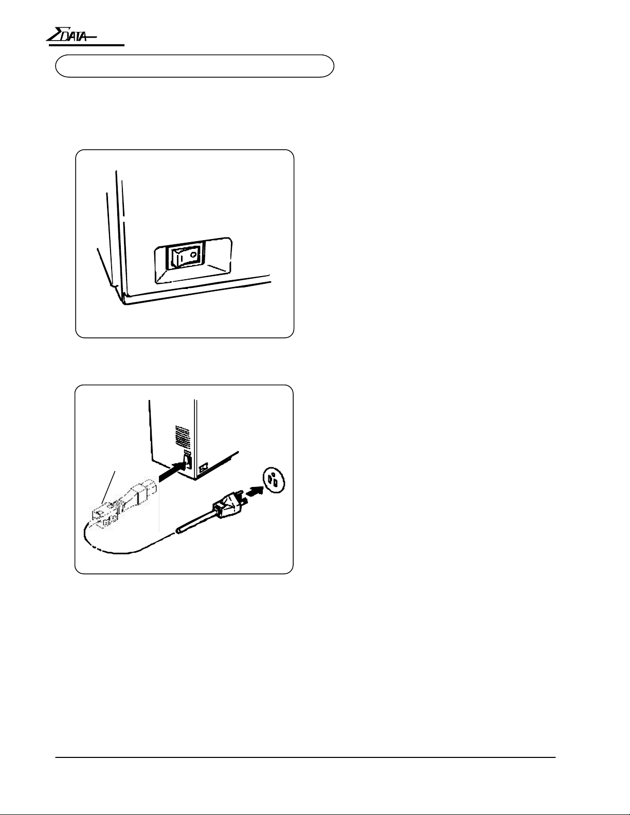
2.1 Connecting the ATB Printer
This section explains how to connect the ATB printer to the power supply and the terminal.
2.1.1 Connecting to a Wall Receptacle
A. Check that the power switch on the
ATB printer is turned off.
B. Plug the power cable into the ATB
printer. Then, plug the other end of the
power cable into a wall receptacle.
Ferrite Core
IMPORTANT...
The Ferrite Core must be attached to the AC Power Cord before the printer is connected to the
wall receptacle. Failure to attach the Ferrite Core to the AC Power Cord may cause non-compliance to:
Note!
Only use the supplied power cable.
Ensure that the power cord complies
with all local ordinances.
FCC Regulations for Class A computing device Canadian ICES-003
EN55022-1 Class A Limits EN50082-1
EN61000-3-2 EN61000-3-3
2-2
Operation Manual
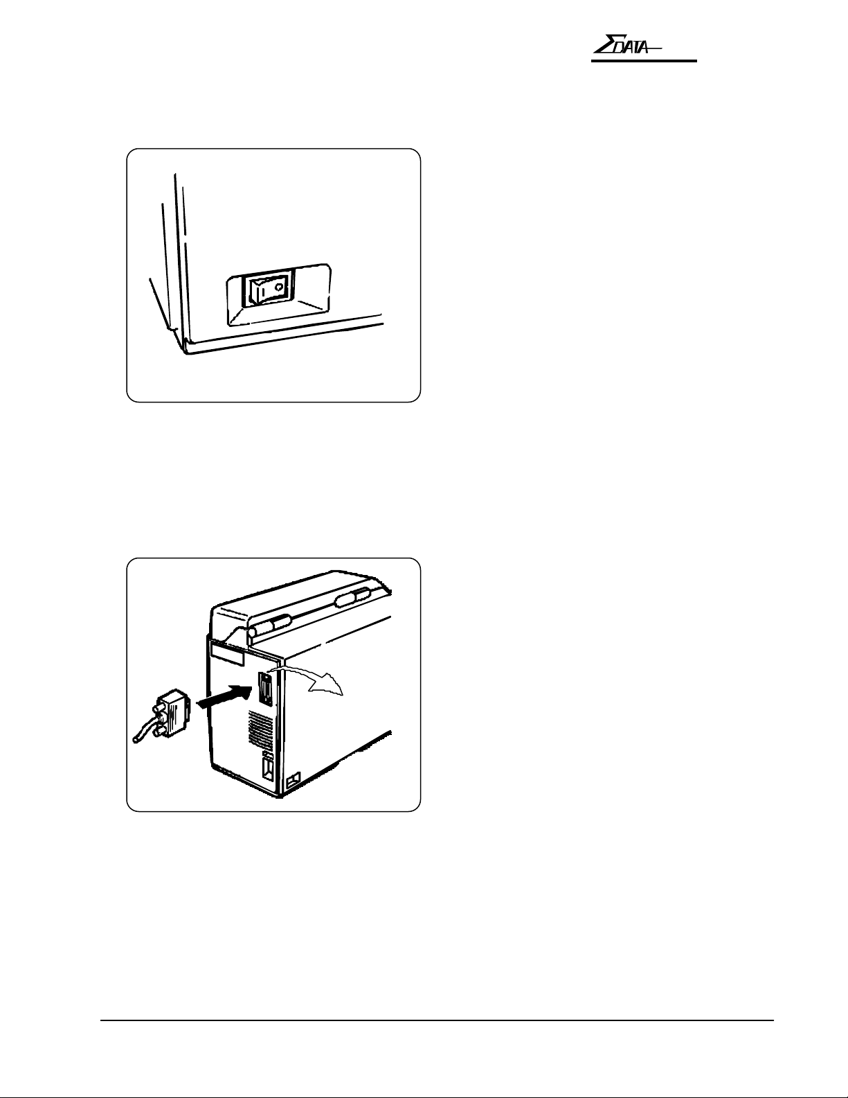
2.1.2 Connecting the Terminal
Before connecting the printer to a terminal, do the following:
A. Ensure that both the ATB printer and the
terminal are turned off.
7200
OPERATION
HOST
B. Attach the communications cable to the
RS-232 port located on the back of the
ATB printer, labeled “HOST.” Then
connect the cable to the terminal.
Operation Manual
2-3
 Loading...